

Page 1
19 561 0121 02 – EN
11 / 01 / 16
Specified cold water limits and added notes for the optional drain pump
19 561 0121 01 – EN
09 / 12 / 15
Update: hydraulic and electric connection from the upper side, Except the models provided with heating tanks
(«boiler»). Improved prescription regarding supply water.
REV. DOC.
DATE
NOTES
INSTALLATION REQUIREMENTS
WD6010 – GW6010
SMEG S.p.A. thank you for choosing this product.
Pre-installation operations (to be performed by the client):
room preparations (as needed)
pre-installation of properly operating systems, in compliance with the requirements and
regulations in force
positioning of the machine
Refer to this manual for detailed instructions on the steps mentioned above.
SMEG S.p.A. declines responsibility for damage to persons or property resulting from improperly
regulated or defective systems or for any installation of the appliance and/or accessories performed by
unauthorized personnel.
Any operation performed on the appliance by unauthorized personnel will invalidate the warranty.
1
Page 2
WD6010-GW6010 INSTALLATION REQUIREMENTS
CAUTION
It is essential that the electrical system to which the machine is connected complies with current regulations.
All electrical testing operations and equipment installation should be made by qualified and trained personnel.
The designated personnel is responsible for ensuring the safety and efficiency of earth connection.
Components must always be replaced with genuine spare parts.
CIRCUIT-BREAKER
A CIRCUIT-BREAKER must be installed for each appliance.
Circuit-breaker characteristics:
a. Omnipolar: must break all live conductors;
b. Easily accessible to the user;
c. Easily operated (no additional tools required);
d. Located in close proximity to the appliance;
e. Clearly marked as the appliance circuit-breaker
The same specifications apply to the main switch on the machine: it must be easily accessible. Do not place
objects in a way that limits accessibility.
A PROTECTIVE DEVICE specifically for the appliance (e.g. magneto thermal breaker or fuse on every phase, with
appropriate dimensions based on the electrical characteristics indicated) should be installed in the room’s
electrical panel.
ELECTRICAL SYSTEM REQUIREMENTS
Refer to the Technical Data sheet to recognize the device’s electrical characteristics and connection requirements.
The device is supplied with a cable with insulated wire terminals; it is not supplied with a plug. The electrical connection of
the device must be carried out with a permanent connection.
2
Page 3
WD6010-GW6010 INSTALLATION REQUIREMENTS
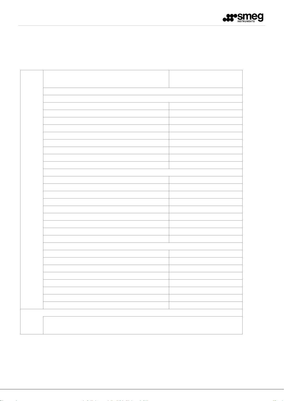
Technical data
Water connections
Microbial contamination limits - Minimum microbiological
quality required:
“drinking water type” (ref. limits
provided by European Directive
98/83/CE)
"CW" COLD WATER
Connection:
3/4" maschio-male - DN20
Min -Max flow rate:
4 - 12 l/min (0,88-2,64 gal/min)
Min - flow pressure:
100 kPa (1,0 bar)
Max. pressure:
600 kPa (6,0 bar)
Min-Max. temperature:
8°C - 35 °C (46-90°F)
Max. hardness:
10 °f
Ferro Max - Fe2+ / Fe3+ [max]
0,5 ppm
pH:
7÷8
"HW" WARM WATER
Connection:
3/4" maschio-male - DN20
Min/Max flow rate:
4 - 12 l/min (0,88-2,64 gal/min)
Min. flow pressure:
100 kPa (1,0 bar)
Max. pressure:
600 kPa (6,0 bar)
Max. temperature:
60°C (140°F)
Max. hardness:
10 °f
Fe2+ / Fe3+ [max]
0,5 ppm
pH:
7÷8
"DW" DEMI WATER
Connection:
3/4" maschio-male - DN20
Min/Max flow rate:
4 - 12 l/min(0,88-2,64 gal/min)
Min. flow pressure:
100 kPa (1,0 bar)
Max. pressure:
600 kPa (6,0 bar)
Max. temperature:
60°C (140°F)
Max. hardness:
0 °f (0 ppm CaCO3)
Max. conductivity / pH:
30 µS/cm / 5÷8 pH
TDS max
40 mg/l
Note: if local-regional requirements are more stringent than those prescribed above, the local
requirements shall be followed. It remains the user's responsibility to provide water supply that
comply with the requirements.
3
Page 4
WD6010-GW6010 INSTALLATION REQUIREMENTS
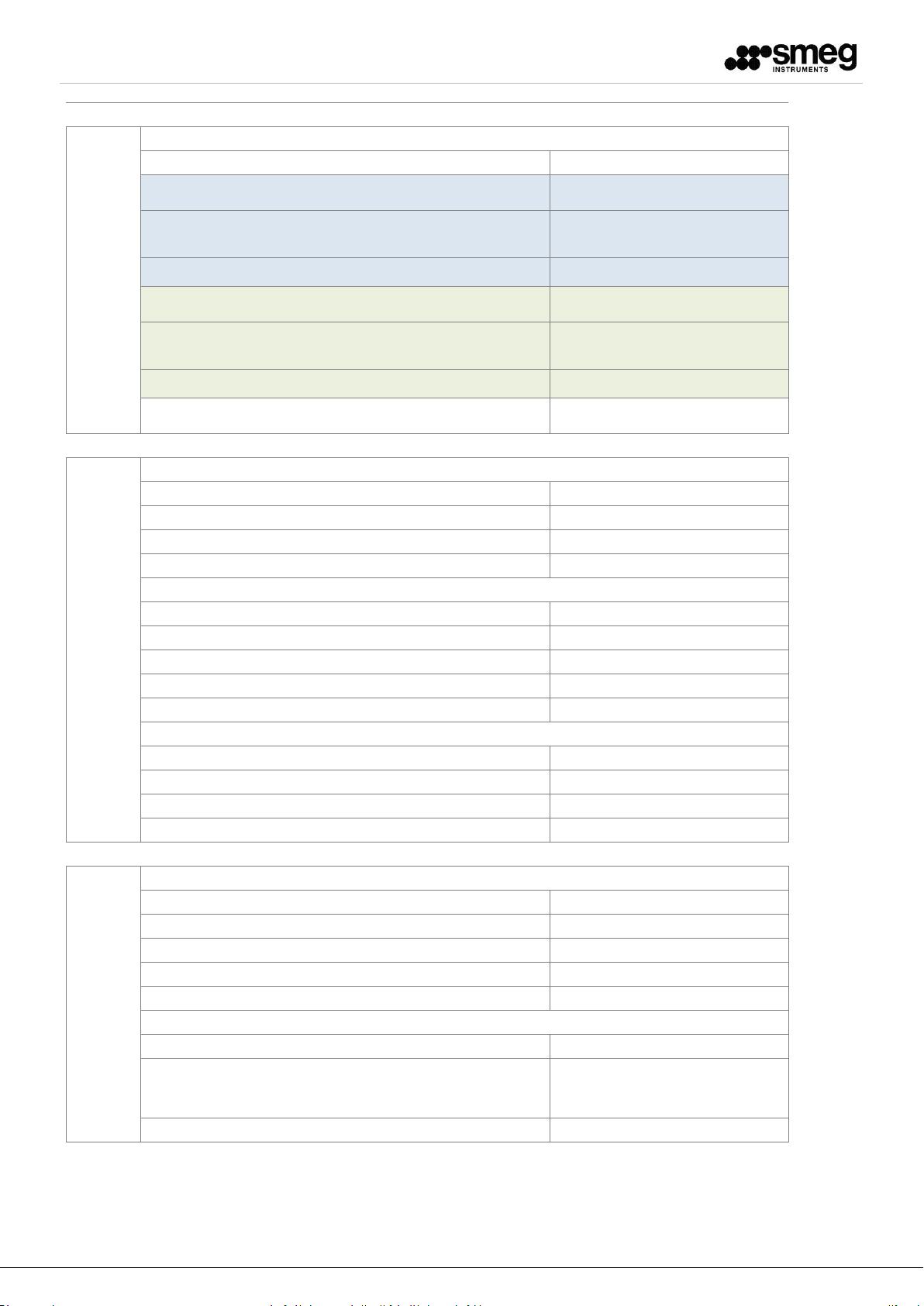
Electrical connections
"EC" Electrical connections
Type:
Standard
Standard Voltage:
400V 3N~ / PE / 50Hz / 24A
Electrical protection required:
3P+N, 32 A
Cable and min. section:
5 x 6 mm2
Configurable Voltage:
230V 3~ / PE / 50Hz / 36A
Electrical protection required:
3P, 40 A
Cable and min. section:
4 x 6 mm2
Potenza - Power:
13 kW
Drain and exhaust
"EX" EXHAUST DUCT
Connection:
ø 50 mm ( 2 in)
Peak flow rate:
approx.220-250 m3/h
Max. temperature:
95 °C (203°F)
"FD" DRAIN FLOOR (standard)
Connection:
ø 50 mm ( 2 in)
Peak flow rate:
50 lt/min (6,6 gal/min)
Max. height:
50 mm ( 2 in)
Max. temperature:
95 °C (203°F)
"D" DRAIN WALL (optional)
Connection:
ø 40 mm (1,6 in)
Peak flow rate:
30 lt/min (6,6 gal/min)
Altezza max. - Max. height:
800 mm (32 in)
Temperatura max. - Max. temperature:
95 °C (203°F)
Others
WEIGHTS
Total net max:
280 kg (617 lb)
Total gross max:
310 kg (683 lb)
Max. on working:
380 kg (837 lb)
Floor load:
600 kg/m
2
(61 lb/ft2 )
ENVIRONMENT
Temperature min-max
T = 10 - 40 °C (50-104°F)
Umidity max:
80% for temperatures up to 31°C
(88°F) with a linear drop to 50%
humidity at 40°C (104°F)
Noise level emission:
< 66 dB (A)
4
Page 5

WD6010-GW6010 INSTALLATION REQUIREMENTS
NOTES
1) It is the customer’s responsibility to insure that the specified pressure ranges are respected (water
mains and, if applicable, steam and air pressure). The pressure has to be measured at the point of
connection to the device.
2) It is customer’s responsibility to provide, if necessary, shock arrestors and / or pressure regulators
to eliminate water hammer conditions.
3) It is customer’s responsibility to provide shutoff valves for incoming cold, hot, demineralized water,
and steam and air (optional). The valves must always be easily accessible to the operator.
4) It is the customer’s responsibility to provide a proper drainage system based on the requirements of
the device and in accordance with national and local regulations. It is necessary to prevent backflow
to the device.
5) Steam exhaust: It is customer’s responsibility to ensure that the ducts are constructed to prevent
the accumulation of condensate. If the machine is connected to free discharge pipes for
steam/fume exhaust, condensation deposit in pipes must be prevented. Moreover, this section of
the machine must be equal to or higher than the given dimensions and there must not be areas
with condensation deposits. In case of fume extraction, the clearances as shown in the schemes
must be observed. At any rate the indicated flow rates must be observed and the materials must be
resistant to the expected temperatures.
6) Even in case of two or more machines installed side by side, the service area required must be
respected.
7) In case of double-door machines, it is customer’s responsibility to provide a barrier wall for the
separation between the loading side (unclean side) and the unloading side (clean side).
Smeg S.p.A.
Instruments Division
Via Leonardo da Vinci, 4 – 42016 GUASTALLA - R.E.
Tel +39 0522 8211 – Fax +39 0522 821 592
E-mail: instruments@smeg.it – www.smeg-instruments.com
5
Page 6

WD6010 - GW6010
EN - DOUBLE DOOR
EN - Note: Except the model provided with heating tanks («boiler»),
starting from the 06/11/2015 the devices are prepared
for hydraulic and electric connection from the upper side.
SHUT-OFF VALVES NOT SUPPLIED
Via Leonardo da Vinci,4
Via Leonardo da Vinci,4
42016 Guastalla (RE) ITALIA
42016 Guastalla (RE) ITALIA
S.p.A
S.p.A
LA RIPRODUZIONE O LA CESSIONE DEL PRESENTE
DISEGNO DEVONO ESSERE AUTORIZZATE DALLA
ANY REPRODUCTION OR TRANSFER OF THE
PRESENT DRAWING MUST BE AUTHORIZED BY
FORM. A4
“SMEG” SPA
“SMEG” SPA
DOC. - DOC.ID
INSTALLATION
REQUIREMENTS
COD. DOC.
195610121.02 - A
DATA - DATE
11.01.2016
Page 7

WD6010 - GW6010
EN - DOUBLE DOOR
(860460)
750
WALL OPENING
650
UNIT WIDTH
1990
1942
- UNIT HEIGHT
WALL OPENENING
OUT
UNLOADING SIDE (CLEAN)
712
UNIT DEPTH
70
30
HANDLE
LOADING SIDE (UNCLEAN)
753
IN
860
FRONT VIEW LOADING SIDE
MAINS SWITCH
UNLOADING SIDE (CLEAN)
852
LOADING SIDE (UNCLEAN)
PLANT VIEW
SIDE VIEW
450
MAX 120
SERVICE CLEARANCE (BOTH SIDES)
MAINS SWITCH
CLEARANCE AREA - FUNCTIONAL ACCESS (BOTH SIDES)
Via Leonardo da Vinci,4
Via Leonardo da Vinci,4
42016 Guastalla (RE) ITALIA
42016 Guastalla (RE) ITALIA
S.p.A
S.p.A
LA RIPRODUZIONE O LA CESSIONE DEL PRESENTE
DISEGNO DEVONO ESSERE AUTORIZZATE DALLA
ANY REPRODUCTION OR TRANSFER OF THE
PRESENT DRAWING MUST BE AUTHORIZED BY
FORM. A4
“SMEG” SPA
“SMEG” SPA
DOC. - DOC.ID
INSTALLATION
REQUIREMENTS
COD. DOC. DATA - DATE
195610121.02 - B
11.01.2016
Page 8

WD6010 - GW6010
WD6010 - GW6010
EN - DOUBLE DOOR
EN - Cconnections from above
NOTE: THE CONNECTION CAN BE ARRANGED
ALSO ON THE LEFT SIDE
STEAM AND AIR EXAUST
EX
90
HW
EC
30
30
EC
HW CW DW
CW
DW
EN - Note - Exception: For models equipped with boilers,
the «upper side» connection system is not available.
Max 2600
2000
DRAIN LOCATION AREA
FEET Ø50X4
165
FD
FRONT VIEW LOADING SIDE
430
Ø 50
FD
325
84
480
110
Max 600
UNLOADING SIDE (CLEAN)
140
50
85 543
LOADING SIDE (UNCLEAN)
Max 1200
Max 1600
50
PLANT-TOP VIEW
EX
Ø50
260
Via Leonardo da Vinci,4
Via Leonardo da Vinci,4
42016 Guastalla (RE) ITALIA
42016 Guastalla (RE) ITALIA
S.p.A
S.p.A
PLANT - BASAMENT VIEW
LA RIPRODUZIONE O LA CESSIONE DEL PRESENTE
DISEGNO DEVONO ESSERE AUTORIZZATE DALLA
ANY REPRODUCTION OR TRANSFER OF THE
PRESENT DRAWING MUST BE AUTHORIZED BY
FORM. A4
“SMEG” SPA
“SMEG” SPA
DOC. - DOC.ID
INSTALLATION
REQUIREMENTS
COD. DOC. DATA - DATE
195610121.02 - C
11.01.2016
Page 9

WD6010 - GW6010
WD6010 - GW6010
EN - SINGLE DOOR
EN - Note: Except the model provided with heating tanks (»boiler»),
starting from the 06/11/2015 the devices are prepared
for hydraulic and electric connection from the upper side.
SHUT-OFF VALVES NOT SUPPLIED
Via Leonardo da Vinci,4
Via Leonardo da Vinci,4
42016 Guastalla (RE) ITALIA
42016 Guastalla (RE) ITALIA
S.p.A
S.p.A
LA RIPRODUZIONE O LA CESSIONE DEL PRESENTE
DISEGNO DEVONO ESSERE AUTORIZZATE DALLA
ANY REPRODUCTION OR TRANSFER OF THE
PRESENT DRAWING MUST BE AUTHORIZED BY
FORM. A4
“SMEG” SPA
“SMEG” SPA
DOC. - DOC.ID
INSTALLATION
REQUIREMENTS
COD. DOC. DATA - DATE
195610121.02 - D
11.01.2016
Page 10

WD6010 - GW6010
EN - SINGLE DOOR
(860457)
650
UNIT WIDTH
1942
- UNIT HEIGHT
712
UNIT DEPTH
753
70
30
HANDLE
IN
860
50
712
FRONT VIEW
PLANT VIEW
MAINS SWITCH
SERVICE CLEARANCE (BOTH SIDES)
450
MAINS SWITCH
CLEARANCE AREA - FUNCTIONAL ACCESS
SIDE VIEW
Via Leonardo da Vinci,4
Via Leonardo da Vinci,4
42016 Guastalla (RE) ITALIA
42016 Guastalla (RE) ITALIA
S.p.A
S.p.A
LA RIPRODUZIONE O LA CESSIONE DEL PRESENTE
DISEGNO DEVONO ESSERE AUTORIZZATE DALLA
ANY REPRODUCTION OR TRANSFER OF THE
PRESENT DRAWING MUST BE AUTHORIZED BY
FORM. A4
“SMEG” SPA
“SMEG” SPA
DOC. - DOC.ID
INSTALLATION
REQUIREMENTS
COD. DOC. DATA - DATE
195610121.02 - E
11.01.2016
Page 11

WD6010 - GW6010
EN - «UPPER SIDE» CONNECTIONS
EN - SINGLE DOOR
STEAM AND AIR EXHAUST
AIR VENTING
SYSTEM
EX
30
30
EC
EC
HW
HW
CW
DW
CW
DW
2000
Max 1600
EN - Note - Exception: For models equipped with «boilers» (heating tanks),
the «upper side» connection system is not available.
Max 2600
FRONT VIEW
DRAIN LOCATION AREA
165
430
FD
FD
Ø 50
110
Max 1200
Max 600
UNLOADING SIDE (CLEAN)
140
50
C W, H W ,
DW, EC (D)
15015085
SIDE VIEW
NOTE: THE CONNECTION CAN BE ARRANGED
ALSO ON THE LEFT SIDE OR ON THE REAR.
BOTH SIDES
EX
75
15
FEET Ø50X4
84
PLANT - BASAMENT VIEW
Via Leonardo da Vinci,4
Via Leonardo da Vinci,4
42016 Guastalla (RE) ITALIA
42016 Guastalla (RE) ITALIA
S.p.A
S.p.A
480
325
LA RIPRODUZIONE O LA CESSIONE DEL PRESENTE
DISEGNO DEVONO ESSERE AUTORIZZATE DALLA
ANY REPRODUCTION OR TRANSFER OF THE
PRESENT DRAWING MUST BE AUTHORIZED BY
FORM. A4
“SMEG” SPA
“SMEG” SPA
85 543
LOADING SIDE (UNCLEAN)
DOC. - DOC.ID
INSTALLATION
REQUIREMENTS
Ø50
260
50
PLANT-TOP VIEW
COD. DOC. DATA - DATE
195610121.02 - F
11.01.2016
Page 12

MACHINE WITH OPTIONAL
DRAIN PUMP INSTALLED
Connecting the exhaust pipe
Ø 40
(BOTH SIDES)
500
MAX
D
MAX 800
Via Leonardo da Vinci,4
Via Leonardo da Vinci,4
42016 Guastalla (RE) ITALIA
42016 Guastalla (RE) ITALIA
S.p.A
S.p.A
FRONT VIEW
LA RIPRODUZIONE O LA CESSIONE DEL PRESENTE
DISEGNO DEVONO ESSERE AUTORIZZATE DALLA
ANY REPRODUCTION OR TRANSFER OF THE
FORM. A4
PRESENT DRAWING MUST BE AUTHORIZED BY
“SMEG” SPA
“SMEG” SPA
DOC. - DOC.ID
INSTALLATION
REQUIREMENTS
COD. DOC. DATA - DATE
195610121.02 - G
11.01.2016
 Loading...