

GW2045 – GW2045C
GW1060 – GW1060C
GLASSWARE WASHER
OPERATING INSTRUCTIONS MANUAL
The machine must only be installed, serviced and repaired by
authorized personnel.
The warranty could become void if the machine is used in a way that
Fails to Conform to the instructions given by SMEG.
19 390 2172 01
03/03/2011
Rev.
Date
CAREFULLY READ THIS INSTRUCTION MANUAL
Failure to read or fully understand the instruction manual, or incorrect interpretation of the
instructions herein may cause damage to the appliance as well as being a source of
danger for the operator and lowering the performances provided by the machine to a
considerable extent.
The manufacturer declines all liability for uses differing from those listed below.
This manual is for informational purposes only. The contents of this manual and the
appliance described herein may be liable to modification without prior notice. In no case
may SMEG be held liable for any direct or accidental damages deriving from or concerning
the use of this manual.

Information or Assistance for products from the
SMEG Instruments Division
Our Sales Office staff will give you all the info you require about prices and offers.
Our Technical Assistance Office staff can tell you how to operate your appliance in the
correct way or put you in contact with your nearest Authorized Assistance Centre if
necessary.
instruments@smeg.it
Fax +39 0522 821 593
Tel +39 0522 8211
You can examine our entire product range in our Internet web site:
www.smeg-instruments.com
International customers, please contact your local SMEG distributor.

Rev. 0
GW2045 – GW1060 Manual
Pag. 4 di 46
TABLE OF CONTENTS
1. INTRODUCTION .................................................................................................................................... 6
2. KEY TO THE SYMBOLS USED IN THE MANUAL AND ON THE MACHINE ..................................... 7
3. GENERAL RECOMMENDATIONS ........................................................................................................ 8
4. GENERAL SPECIFICATIONS ............................................................................................................... 9
4.1. TECHNICAL FEATURES ....................................................................................................................... 9
4.2. LIFTING AND HANDLING ..................................................................................................................... 12
4.3. DOOR-LOCKING SYSTEM .................................................................................................................. 12
4.4. EMERGENCY UNLOCKING OF DOOR ............................................................................................... 13
4.4.1. UNLOCKING GW2045 ................................................................................................................... 13
4.4.2. UNLOCKING GW1060 ................................................................................................................... 14
5. INSTALLATION .................................................................................................................................... 15
5.1. POSITIONING ....................................................................................................................................... 15
5.2. LEVELLING ........................................................................................................................................... 15
5.3. CONNECTION TO WATER MAINS ...................................................................................................... 15
5.4. NON PRESSURIZED DEMINERALIZED WATER CONNECTION ....................................................... 17
5.5. WATER OUTLET CONNECTION ......................................................................................................... 19
5.6. ELECTRICAL CONNECTION ............................................................................................................... 20
6. DESCRIPTION OF CONTROLS .......................................................................................................... 21
6.1. MAIN PANEL ......................................................................................................................................... 21
6.2. SETUP MODE DESCRIPTION ............................................................................................................. 22
6.3. WASHING PROGRAMME SETTINGS ................................................................................................. 24
6.4. THERMAL DISINFECTION IN ACCORDANCE WITH THE PARAMETER "A0" ................................... 24
6.5. PREPARATION OF LOAD FOR THE WASHING AND DISINFECTING PHASE.................................. 25
6.6. PROGRAMMES DESCRIPTION .......................................................................................................... 26
6.7. CARRYING OUT THE PROGRAMME .................................................................................................. 29
6.8. RESIN REGENERATION AND WASHING PHASE .............................................................................. 29
6.9. END OF CYCLE .................................................................................................................................... 29
6.10. IN PROGRESS PROGRAMME INTERRUPTION ............................................................................... 30
6.11. RESET PROCEDURE ........................................................................................................................ 30
6.12. DATE AND TIME SETUP .................................................................................................................... 30
6.13. COMMUNICATION WITH PRINTER .................................................................................................. 31
7. OPERATING INSTRUCTIONS ............................................................................................................ 33
7.1. USE OF THE WATER SOFTENER ....................................................................................................... 33
7.2. USE OF THE DETERGENT AND NEUTRALIZING AGENT ................................................................. 34
7.3. USING THE DETERGENT DISTRIBUTOR........................................................................................... 34
7.4. LOADING NEUTRALISER .................................................................................................................... 35
7.5. OPTIONAL ACCESSORIES ................................................................................................................. 36
7.5.1. PERISTALTIC PUMPS P1 AND P3 (ACCESSORY “SMEG ADU”) .............................................. 36
7.5.2. DETERGENT CAN LEVEL SENSORS .......................................................................................... 37
7.6. PRECAUTION WHEN USING DETERGENTS. .................................................................................... 38
8. ALARMS ............................................................................................................................................... 39
9. CLEANING AND MAINTENANCE ....................................................................................................... 42

Rev. 0
GW2045 – GW1060 Manual
Pag. 5 di 46
9.1. RECOMMENDATIONS AND GENERAL ADVICE ................................................................................ 42
9.2. IF THE GLASSWARE WASHER IS NOT USED FOR A LONG PERIOD OF TIME .............................. 44
9.3. REUSING THE GLASSWARE WASHER AFTER A LONG STANDSTILL PERIOD ............................. 44
9.4. TROUBLESHOOTING .......................................................................................................................... 44
10. INSTALLATION DIAGRAM GW2045 – GW1060 ................................................................................ 45

Rev. 0
GW2045 – GW1060 Manual
Pag. 6 di 46
1
All technical controls must be carried out solely by specialised, authorised Smeg
staff.
In addition to being the cause of cancellation of any warranty cover, any repairs
carried out by non-authorised staff may be a source of danger for the user.
The machine must only be used by specifically trained persons. It is Smeg’s task to
train the designated users when the appliance is installed.
Smeg declines all liability for malfunctioning or accidents due to the appliance
having been used by untrained persons.
1
1. INTRODUCTION
This manual is an integral part of the machine
It must be kept in a good condition and ready to hand for the entire life cycle of the machine.
You are advised to carefully read this manual and all the instructions it contains before using the
appliance.
This appliance has been built for the following function:
Washing with Thermal Disinfection
the appliance cannot be used to sterilize instruments or any other device.
All other use is considered improper.
The manufacturer declines all liability for uses differing from those indicated.
SMEG declines all responsibility for any possible damage caused by the washing of instruments
whose manufacturers have not authorized to be automatically decontaminated.
The glassware washers correspond to all the requisites set by the current safety laws in force
regarding electrical equipment.
The appliance is compliant with the applicable directives currently in force (2006/95/CEE low voltage
directive, 2004/108/CEE electromagnetic compatibility, 93/68/CEE EC labelling).
or Thermodisinfection of laboratory glassware;
The machine carries out Thermal Disinfection at varying temperatures and exposure times depending on the programme selected (the
operator that selects the programme according to the current regulations and laws in force in the place of use).
The treatment can never be a substitute for sterilizing. Disinfection is carried out to reduce the risks sustained by the persons who
handle surgical instruments when preparing them for subsequent usage.
Rev. 0
GW2045 – GW1060 Manual
Pag. 7 di 46
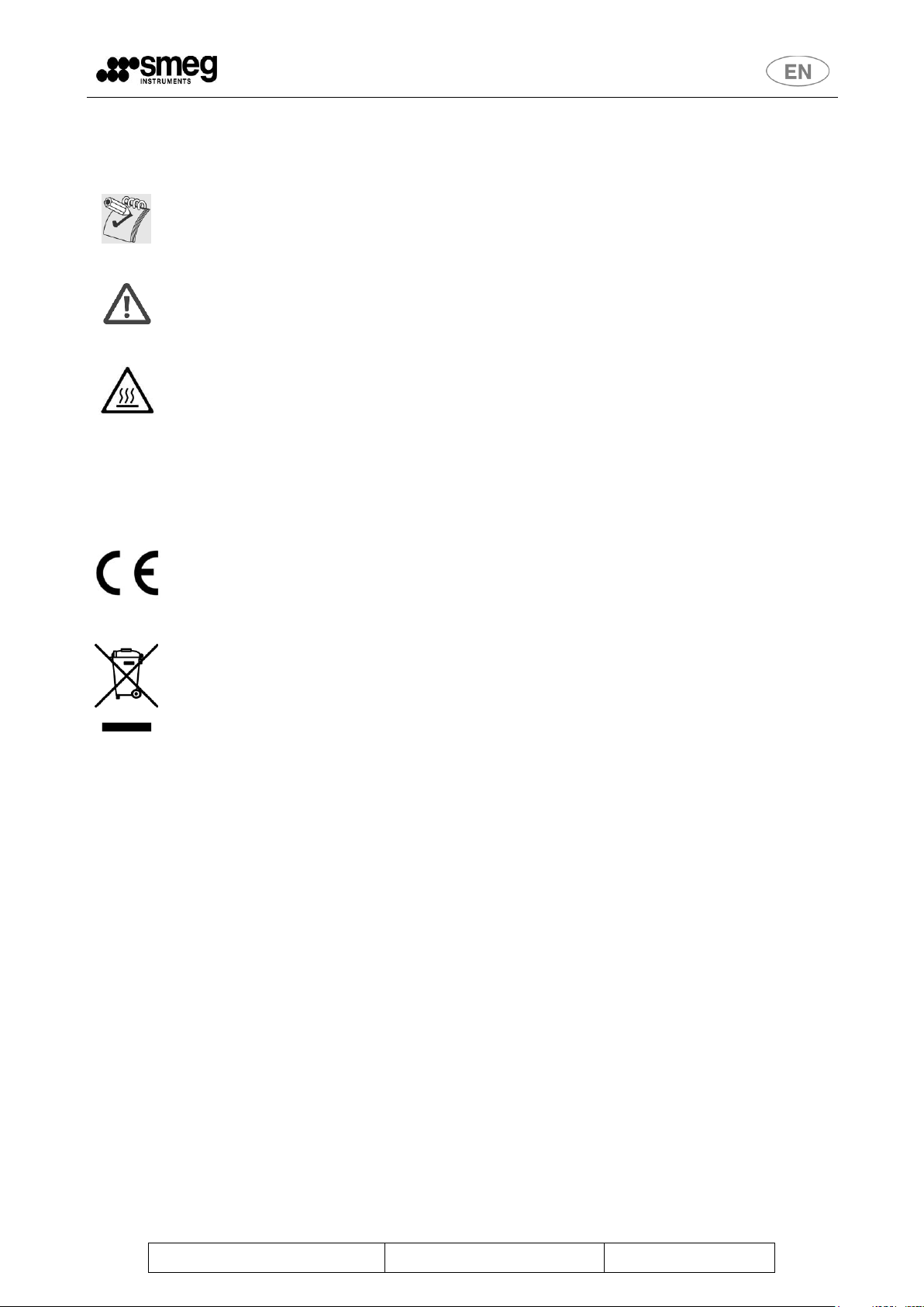
Carefully read the paragraph.
Warning, danger: consult the manual
Attention, hot surface.
~
Alternating current.
CE labelling.
At the end of life the product should be sent to disposal facilities for the recovery and
recycling.
2. KEY TO THE SYMBOLS USED IN THE MANUAL AND ON THE
MACHINE
Rev. 0
GW2045 – GW1060 Manual
Pag. 8 di 46
Never use solvents such as alcohol or turpentine in the appliance as they could
cause an explosion. Do not place materials dirtied with ash, wax or paint in the
appliance.
Open the door carefully ONLY when the washing cycle has finished.
Do not open the door while the washing cycle is in progress. If you open the door
while a programme is in progress, hot water, steam and other liquids will spill out
and may injure the user. Only authorized and well-informed personnel are allowed
to use the machine.
3. GENERAL RECOMMENDATIONS
Do not rest or sit on the open door of the glassware washer as this could cause the appliance to tip over
and endanger persons. The door‟s primary functions is not to bear weights or loads. The maximum
weight loaded onto the open door, including the weight of the instrument trolley, must never exceed
25kg.
Never touch the heating element immediately after a wash programme has finished.
The heating coil may darken slightly, even only in places, while the glassware washer is in use. This is
normal as it depends on the operating mode and will in no way impair the way the appliance operates.
Discarded appliances must be rendered unusable. Cut the power cable after removing the plug from the
electrical socket. After this, the appliance must be consigned to a differentiated waste collection center.
If any irregularities are noted, detach the power supply and close the water tap. After having done this,
call the nearest authorized Assistance Center.
Rev. 0
GW2045 – GW1060 Manual
Pag. 9 di 46
ELECTRICAL POWER SUPPLY GW2045
TYPE OF VOLTAGE
[tolerated variation 10%]
230V ~
FREQUENCY [HZ]
50
POWER RATING [KW]
3.3
ELECTRICAL POWER SUPPLY GW1060
MODELS GW1060
GW1060
GW1060-3
GW1060-1
VERSION
Triphase 400V
Triphase 230V
Monophase 230V
TYPE OF VOLTAGE
[variaz. variation 10%]
400V 3/N/E
230V 3/PE
230V 1/N/PE
FREQUENCY [HZ]
50
POWER RATING [KW]
7 kW
7 kW
2.8 kW
AUTOMATIC SWITCH ON MACHINE
(ICN IS THE NOMINAL SWITCH POWER DURING
SHORT CIRCUIT)
In 16A 3P+N 400V Icn
4500 A
In 20A 3P 400V Icn
6000 A
In 16 A P+N 230V Icn
4500 A
DATA CONNECTION – FOR ALL MODELS
COMMUNICATION WITH
PRINTER
DOOR RS232
WATER SUPPLY - FOR ALL MODELS
TYPE OF WATER
COLD WATER
DEMINERALISED
WATER
PRESSURE [BAR]
2 – 5
2 - 5
MIN-MAX CAPACITY [L/MIN]
4-10
4-10
TYPE OF CONNECTION
3/4”
3/4”
MAX HARDNESS [°f] /
CONDUCTIVITY [S/CM]
42°f
Max 20μS
IRON [PPM] FE MAX
< 0.5
4. GENERAL SPECIFICATIONS
4.1. TECHNICAL FEATURES

Rev. 0
GW2045 – GW1060 Manual
Pag. 10 di 46
WATER DRAINAGE
FROM FLOOR LEVEL (on which machine is placed)
"GW2045 - GW1060" FAMILIES WITHOUT STEAM CONDENSER
HEIGHT [MM]
Min 400 - Max 800
DIAMETER [MM]
Min 40
“GW2045C” WITH STEAM CONDENSER
NOTE: Model GW2045C, though equipped with steam condenser, has a single exhaust pipe
into which the machine exhaust fumes and steam condenser are conveyed.
HEIGHT [MM]
Min 150 - Max 600
DIAMETER [MM]
Min 40
“GW1060C” WITH STEAM CONDENSER
NOTE: model GW1060C is equipped with two exhaust pipes, one for the tank and one for the
condenser. It requires two water connections for draining.
HEIGHT [MM]
Min 650 - Max 800
DIAMETER [MM]
Min 40
GW2045C
150mm < A < 600mm
B < 600mm
The steam condenser is only furnished on models in the families GW2045C and GW1060C
Rev. 0
GW2045 – GW1060 Manual
Pag. 11 di 46
GLASSWARE WASHER MEASUREMENTS
HEIGHT [MM]
850
DEPTH [MM]
GW2045: 620mm – GW2045C: 670mm – GW1060: 670mm
WIDTH [MM]
GW2045: 450mm – GW1060: 600mm
NET WEIGHT [kg]
GW2045: 50kg – GW1060: 65kg
Material used
Washing tub AISI 316L
Outer coating AISI 304
ENVIRONMENTAL CONDITIONS
USE
Indoors
ALTITUDE
Up to 1000 metres
TEMPERATURE
From 5°C to 40°C
RELATIVE HUMIDITY
80% for temperatures up to 31°C with linear reduction
Up to 50% to temperature of 40°C
INSTALLATION CATEGORY
II
POLLUTION DEGREE
2 (ref. 61010-1, par.3.6.6.2)
Maximum sound pressure (dB)
60
Rev. 0
GW2045 – GW1060 Manual
Pag. 12 di 46
Before it leaves the factory, the base of the machine is fixed to a pallet which is then
used to lift and transport the machine itself.
The machine must be handled with a fork-lift truck or transpallet.
Do not use appliances damaged by transport! Consult your dealer if in doubt.
The appliance must only be installed and connected by personnel authorized by the
manufacturer.
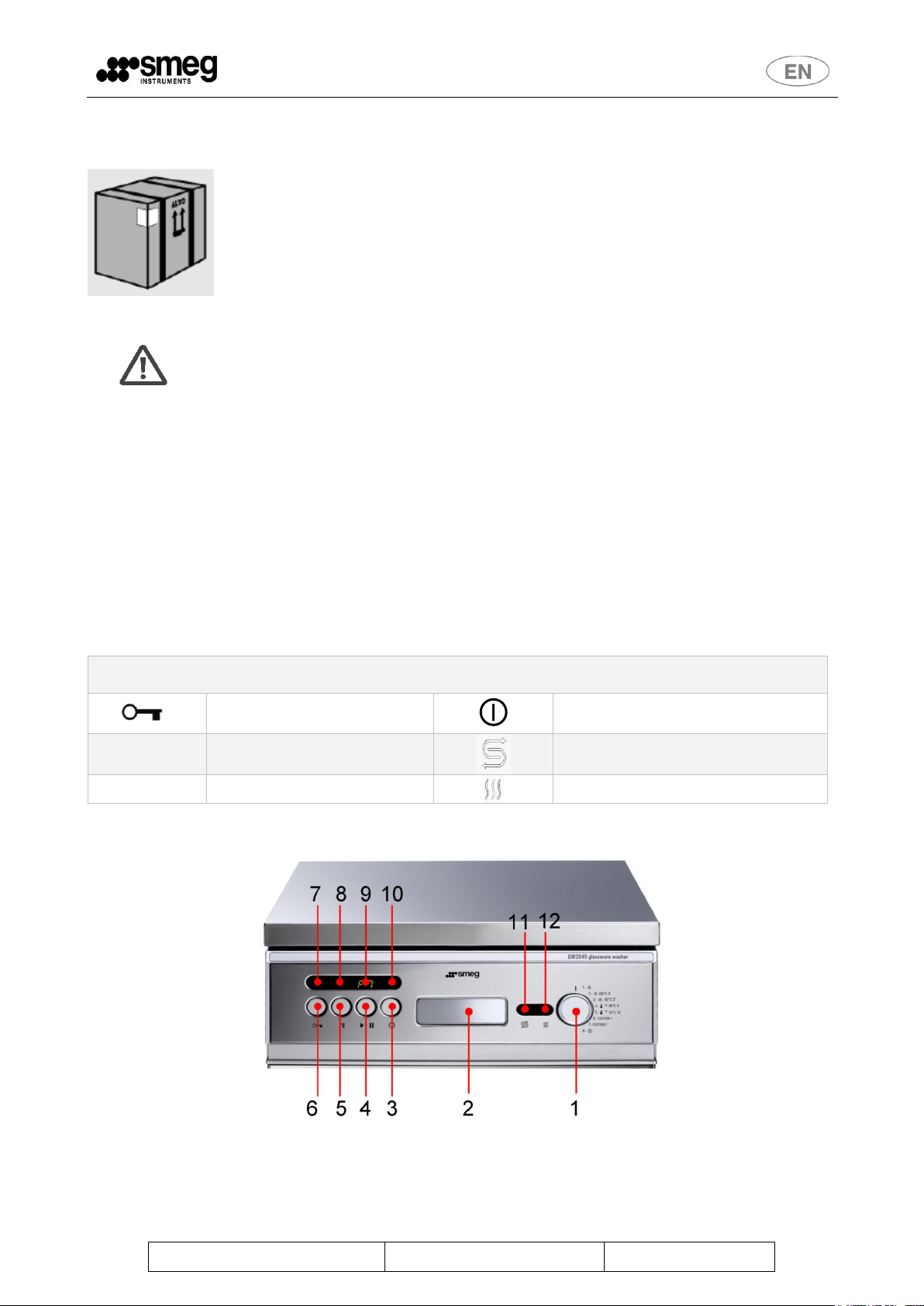
SIGNS ON THE FRONT OF THE MACHINE
Door unlocking
ON / OFF
°C
Temperature
Salt Lack
► ll
START / PAUSE
HEATING ELEMENT ON
4.2. LIFTING AND HANDLING
4.3. DOOR-LOCKING SYSTEM
After unpacking, pay attention to the following: the machine is equipped with an automatic door
locking/unlocking system. The door is locked.
Don’t force the door, but follow the procedure below.
Connect the machine to the mains supply;
push the ON/OFF button (in order to switch on the machine)
Press the button that has the KEY symbol on it: The door will open automatically after a few
moments.
In order to open the door without connecting the machine to the mains, the manual unlocking procedure
must be executed (see section below).
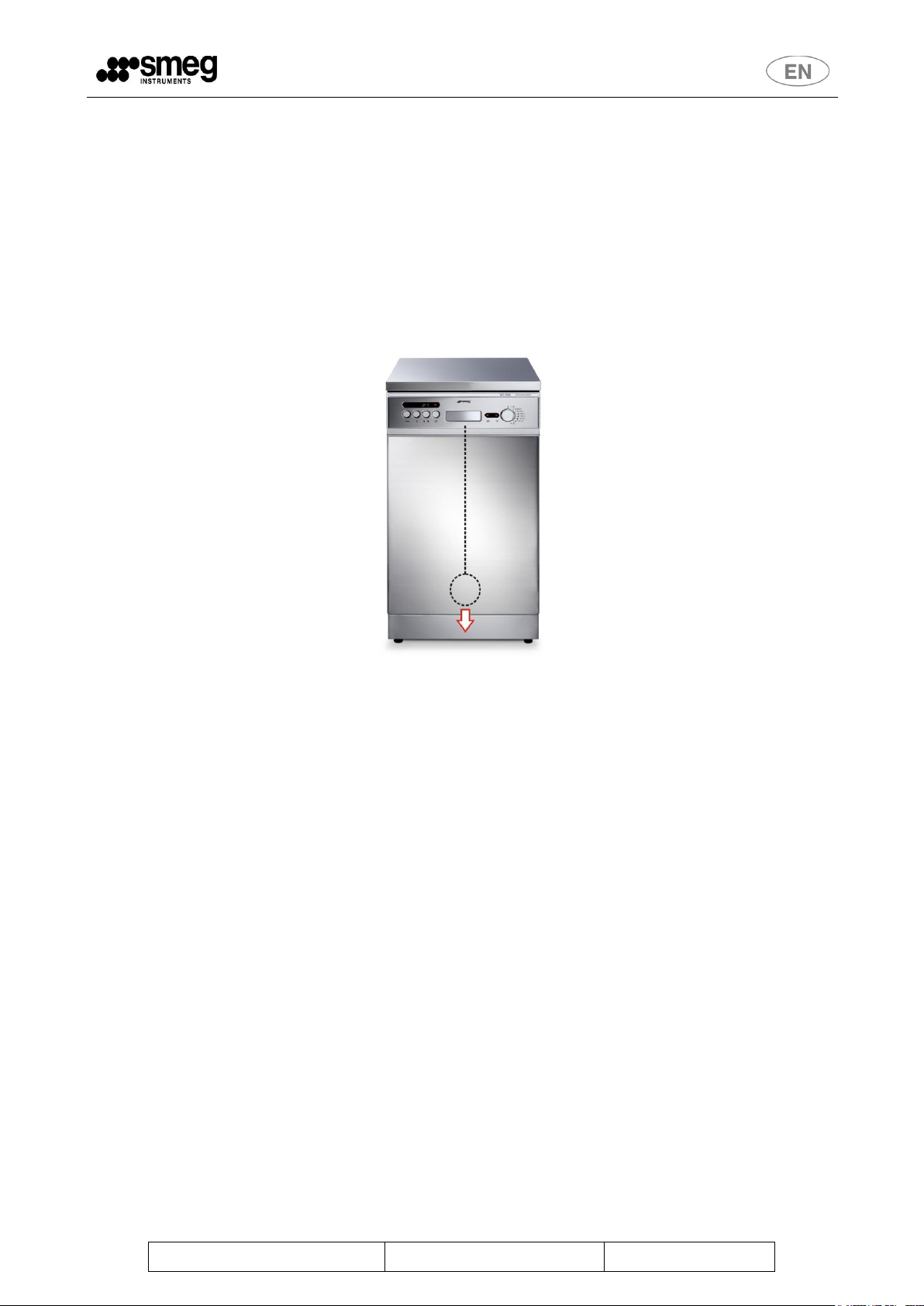
fig. 1 – Front of the GW2045. To unlock the door it is necessary to: Turn on the machine (ON/OFF symbol), 2 – Press the button with
the KEY symbol (first button on left) and wait a few seconds.
Rev. 0
GW2045 – GW1060 Manual
Pag. 13 di 46
4.4. EMERGENCY UNLOCKING OF DOOR
4.4.1. UNLOCKING GW2045
If any malfunction occurs, or in the event of a blackout, it is possible to open the appliance manually.
The appliance has a manual door opening device: a rubber ring with a cable that works directly on the
locking device hidden in the centre of the lower part of the door.
To open the door manually: pull the rubber ring downwards gently until the door clicks open.

Rev. 0
GW2045 – GW1060 Manual
Pag. 14 di 46
4.4.2. UNLOCKING GW1060
If the event of malfunctions or of a blackout, it is possible to open the door manually, carefully using a slim
screwdriver on the opening mechanism, avoiding damage to the device. Warning Before opening the
appliance manually, disconnect from the mains.
fig. 2 – Front of the GW1060. To unlock the door manually, it is necessary to: 1 – push the opening handle to access the opening
mechanism, 2 – Force the opening mechanism, pushing upwards.
Insert a screwdriver into the slot behind the handle and press gently until the mechanism clicks. The area is
marked by the arrow in the picture below.

Rev. 0
GW2045 – GW1060 Manual
Pag. 15 di 46
IMPORTANT: The machine must be positioned against the wall (minimum distance 10
mm) and must be installed by a technician authorized by Smeg.
The technician who installs the machine is responsible for the appliance operating
correctly after it has been installed. He is also obliged to provide the user with all
the information required to use the machine in the correct way.
During installation, the scratch protection film must be removed from the outer steel
surfaces.
The appliance MUST NOT be used by unauthorised or untrained staff.
2
5. INSTALLATION
The diagrams containing the machine‟s measurements and the recommended positions for drainage can be
found at the back of the manual.
IT IS SEVERELY FORBIDDEN FOR UNAUTHORISED PERSONS TO USE THE APPLIANCE.
5.1. POSITIONING
The side panels of the machine can adhere to the adjacent furniture and care must be taken to leave space
at the rear: it is therefore advisable for the wall at the back to be made of brickwork or some other
impermeable material.
The machine has pipes to supply and drain off the water. These can be positioned towards the right or left,
depending on the installation requirements.
The machine can also be installed under a work top: This operation must be carried out by specialised staff.
5.2. LEVELLING
Once the machine has been set in position, it must be levelled until horizontal (2 degrees tolerance allowed)
by either screwing in the feet or unscrewing them.
Correct levelling will ensure that the machine operates in the right way.
5.3. CONNECTION TO WATER MAINS
See section "INSTALLATION DIAGRAM GW2045-GW1060” at the back of the manual.
Notes for preventing risks of blockage or damage: If the water pipes are new or have not been used for a
long time, check that the water is clear and clean before attaching to water mains.
A non-return device can be found inside the appliance, in agreement with the current regulations in forces,
EN 617702.
The pipe is designed to be attached to a tap with a threaded ¾” gas bushing.
Use the filter supplied, “A” in the picture, to connect the end of the drainage pipe.
fig. 3 - insert the filters supplied when connecting the filling pipe.
Standard CEI EN 61770 “Electronic appliances connected to water mains. Avoidance of back siphonage and failure of hose sets”. (IEC
61770 "Electric appliances connected to the water mains - Avoidance of back siphonage and failure of hose-sets").

Rev. 0
GW2045 – GW1060 Manual
Pag. 16 di 46
WARNING – MAKE SURE THAT:
The water supply pressure is within the working limits:
See the machine‟s technical features table.
The water supply taps are in an easily accessible position
WARNING – Washing stainless steel instruments
Chemical characteristics of mains water which are not compatible with good
washing of materials:
If the supply water contains Fe2+/Fe3+ ions in a quantity greater than 0.5 ppm and/or the
supply water is harder than 42°f (French degrees), the water must be pre-treated by
installing a deferrization and/or water softening system to which the appliance must then
be connected.
IMPORTANT
If demineralised water is not available in the system, do not connect the relative
pipe to the hot and cold water inlets. Leave the “demineralised water” pipe
disconnected.
Read the instructions on “LOADING WITH DEMINERALISED WATER” to set the
parameters correctly.
Keep the water supply taps turned off when the machine is not being used
In the event of instruments dirtied with blood: Make sure that the machine is supplied with water below the
temperature of 40°C.
KEY
D: DRAIN: Water drainage.
CD: CONDENSER DRAIN: steam condenser drain (only on model GW1060C)
CW: COLD WATER: Inlet connection for cold water.
DW: DEMI WATER: Inlet connection for demineralised water.
GW2045
fig. 4 – rear of product GW2045, detail of rear cross-section with indication of water inlets and outlets. The appliance is standard equipped with 1
peristaltic pump for detergent dosage P2. P1 is an optional accessory.

Rev. 0
GW2045 – GW1060 Manual
Pag. 17 di 46
If the PAD pump is used, the water supply pressure must be less than 1 bar.
GW1060
fig. 5 - rear of product GW1060, detail of rear cross-section with indication of water inlets and outlets The appliance is standard equipped with 1
peristaltic pump for detergent dosage: P2. P1 and P3 are optional accessories.
GW1060C
fig. 6 – Back of product GW1060C, diagram detail of the rear crossbar with indication of the water inlets and outlets. In addition to the
connections mentioned above, the model GW1060C provides connection for drainage of the "CD" steam condenser.
5.4. NON PRESSURIZED DEMINERALIZED WATER CONNECTION
The connection to a non-pressurized demineralized water supply (e.g. gravity tank) is possible only by
installing the special demineralized water pump, called "SMEG-PAD".
This pump makes sure that the demineralised water enters at sufficient pressure to make the appliance work
correctly. The PAD accessory can be fitted externally on any machine and must be mounted on the back of
the machine.
We advise having the PAD installed by a specialized SMEG technician.

Rev. 0
GW2045 – GW1060 Manual
Pag. 18 di 46
WARNING – WHEN INSTALLING THE PAD, MAKE SURE THAT:
Make sure that the demineralized water pressure is less than 1bar. Smeg declines all
responsibility if the PAD is installed with the inlet water at a higher pressure.
Smeg will accept no responsibility for any possible damage to items or people
caused by an incorrect installation performed by an unauthorized technician.

Rev. 0
GW2045 – GW1060 Manual
Pag. 19 di 46
IMPORTANT
The outlet must comply with international legislation. Our company will accept no
liability for pollution caused by improper use of the machine.
5.5. WATER OUTLET CONNECTION
The machine is equipped with drainage pipe.
Only the model GW1060C is equipped with two exhaust pipes.
The internal diameter of the pipe is ½ inch therefore it can be attached to any standard ½” rubber holder.
General rules for installing outlet
A siphon drain is recommended. When installing it is necessary to follow the following advice:
As the outlet water is at 95°C, the end of the outlet pipe must be fixed to the rubber holder, using the clips
provided.
The outlet pipe must not have any sharp bends and consequent narrowing.
The end of the outlet pipe must be at a height “A” compared to the surface the appliance stands on:
a. Models GW2045 and GW1060: at a height between min 400mm – Max 800mm.
b. Models GW1060C: at a height between 650mm and 800mm.
c. Models GW2045C: at a height between 150mm and 600mm.
No part of the drain pipe must exceed a height greater than 600mm from the floor on which the
machine is placed. With reference to the figure, it must always be verified: B < 600mm.
The end of the pope must not be immerged in water.
The internal diameter of the outlet pipe must be at least 40 mm.
If possible, install a 50 mm diameter outlet pipe.
The outlet pipe provided with the appliance must not be extended. Any extensions may cause flow-back
problems into the vat.
fig. 7 - Outlet pipe connection.
fig. 8 – adaptor with rubber holder for ½” pipe.

Rev. 0
GW2045 – GW1060 Manual
Pag. 20 di 46
IMPORTANT
GW2045 – The machine has a power cable with a Schuko plug for connection to
electricity main: The plug comprises an appliance sectioning device, which must be
easily accessible for the user.
Wherever possible, prepare a dedicated power sectioning device in the system:
1. Il must be easily accessible for the user.
2. It shall be in close proximity to the equipment.
3. It shall be clearly marked as the sectioning device for the equipment, e.g.
GW2045 DISCONNECTING SWITCH.
Gw1060 – The machine has a power cable for fixed connection to an electrical panel. It is
necessary to prepare a power supply sectioning device (disconnecting switch) in the
system.
1. EASILY ACCESSIBLE
2. CLEARLY MARKED AT THE DISCONNECTING DEVICE FOR THE
APPLIANCE.
Look at the product technical features table at the start of the manual for the correct size
of the disconnecting switch.
IMPORTANT
It is essential for the electricity mains to which the machine is connected to comply with
the current standards in force (CEI 64-8/7;V2 standards3). In all cases, make sure that the
earth socket is effective.
SMEG declines all liability for damage caused by connection to a defective socket that
fails to ensure a perfect connection to the general earth conductor, or by a poorly efficient
grounding circuit.
3
5.6. ELECTRICAL CONNECTION
Refer to the technical features diagram for electrical absorption in the section "GENERAL
SPECIFICATIONS
".
GW2045 - The machine is designed for connection to an electricity main with the following voltage rating:
~ 230V 1 / N / PE 50Hz
GW1060 The machine is designed for connection to an electricity main with the following voltage rating:
~ 400V 3 / N / PE 50Hz (GW1060)
GW1060 Family - There is also a single-phase and 230V three-phase "without neutral", with the following
electrical characteristics:
~ 230V 1 / N / PE 50Hz (GW1060-1)
~ 230V 3 / PE 50Hz (GW1060-3)
CEI 64-8;V2: "Impianti elettrici utilizzatori a tensione nominale non superiore a 1000 V in corrente alternata e a 1500 V in corrente
continua." http://www.ceiweb.it/
fig. 9 - picture showing electrical connection on GW1060.

Rev. 0
GW2045 – GW1060 Manual
Pag. 21 di 46
ID
DESCRIPTION
1
WASHING PROGRAMME SELECTOR
2
RECESSED HANDLE TO OPEN the DOOR
3
ON/OFF KEY
4
START/PAUSE KEY
5
TEMPERATURE DISPLAY KEY
6
DOOR UNLOCKING KEY
7
DEMINERALISED WATER ATTACHMENT LIGHT (turned on if demineralised water attachment
active)
8
TEMPERATURE DISPLAY INDICATOR LIGHT
9
CYCLE INFORMATION DISPLAY (alternates programme/temperature, if light 8 is active, with
programme/phase, if light 8 is turned off)
10
“POWER ON” INDICATOR LIGHT
11
“LACK OF SALT” INDICATOR LIGHT
12
"HEATING ON" INDICATOR LIGHT
SIGNS ON THE FRONT OF THE MACHINE
Door unlocking
ON / OFF
°C
Temperature
Salt Lack
► ll
START / PAUSE
Heating element on
6. DESCRIPTION OF CONTROLS
6.1. MAIN PANEL
All the controls and indicators of the glassware washer are positioned on the front panel.

Rev. 0
GW2045 – GW1060 Manual
Pag. 22 di 46
6.2. SETUP MODE DESCRIPTION
The SETUP function can be accessed on the programme selection switch (see par. DATE AND TIME
SETUP).
Note: Below, in brackets, are the numbers used in the picture to identify the controls.
Procedure for accessing appliance‟s SETUP menu:
Press the ON/OFF button (3) to switch on the machine (If any alarm appears on the display at this
stage, ignore it).
Turn the PROGRAMME SELECTION SWITCH (1) to go to the SETUP position required (see the
description of programmable parameters below).
Press the DOOR OPEN BUTTON (6) for 4 seconds to enter the setup function Wait for the dual
beep as confirmation.
To increase a value press "TEMPERATURE VIEWING" (5) parameter must only be viewed and not
changed.
To decrease a value press START/PAUSE" (4) Do not use this button if the parameter must only be
viewed and not changed.
TO END PROGRAMMING, press the DOOR OPENING (6) button and keep it pressed for 4
seconds. The new settings are now saved.
IF YOU WISH TO EXIT THE SETUP MODE WITHOUT SAVING the parameters you may have
changed, do not press the DOOR OPENING (6) button, but turn off the machine using the ON/OFF
button (3).

Rev. 0
GW2045 – GW1060 Manual
Pag. 23 di 46
Selected Language
German
French
Spanish
Italian
English
Abbreviation on Display
dE
Fr
ES
It
En
Demineralised water attachment
Present
Absent
Abbreviation on Display
dn
--
Setup field
Year
month
day
Time
Minutes
Seconds
Inactive
position
Inactive
position
Switch
position
1 2 3 4 5 6 7
8
SETUP MENU
SETUP menu, available functions:
1. Position 1: For dose of detergent in pump P1. Set the ml/litre required as dose of detergent with
maximum threshold allowed at 20ml/litre. In 1ml steps (increase/decrease by using buttons (5) and
(4)). P1 Default dosage is 5 ml/litre.
2. Position 2: Similar to Position 1 for P2, neutraliser. P2 Default dosage is 3 ml/litre.
3. Position 3: Similar to Position 1 for P3. P3 Default dosage is 0 ml/litre.
4. Position 4: Setting of hardness of water in °f, from 5 to 60 with 5°f steps. Default is a water
hardness of 40°f. Important parameter for the correct functioning of softener incorporated into
appliance.
5. Position 5: Choice for automatic opening of door at end of cycle. “ON” as default. ON and OFF
appear on the display in segments to select the two options.
6. Position 6: Printer language - to be selected from the various languages available; default is
English.
7. Position 7: Demineralised water attachment, yes/no.
8. Position 8: Date-time (for details se paragraph DATE AND TIME SETUP).
It is possible to access and change the following parameters using programme selection and the
buttons (5) and (4):

Rev. 0
GW2045 – GW1060 Manual
Pag. 24 di 46
Temperature – time
A
0
90°C 1‟
600
90°C 5‟
3000
93°C 5‟
6000
93°C 10‟
12000
10
80
0
10
T
A
T
4
6.3. WASHING PROGRAMME SETTINGS
Consult the following table to select the required programme. It gives the washing cycle most able to suit the
nature of the instruments you need to wash and the degree of dirt involved.
Once you have found the most suitable washing programme, turn the PROGRAMME SELECTOR (1) knob
and select the desired programme by setting it to the relative reference number.
PR-1: Pre-wash, Quick washing programme using cold water (soaking glassware while awaiting wash).
PR-2: Washing programme at 60°C suitable for plastic ware.
PR-3: Washing programme at 80°C suitable for plastic ware.
PR-4: Washing + thermo-disinfection at 90°C for 3‟ (A0 =1800).
PR-5: Washing + thermo-disinfection at 93°C for 10‟ (A0 =12000).
PR-6: CUSTOM 1, personalised programme set by authorised SMEG technicians on customer‟s request
(default: the programme carries out wash + thermo-disinfection at 93° for 3‟).
PR-7: CUSTOM 2, personalised programme set by authorised SMEG technicians on customer‟s request
(default: the programme carries out wash + thermo-disinfection at 93° for 10‟, with prewash).
PR-8: Service Programme, start up to test the detergent and neutralizer dispensers (carry out on first start-
up).
6.4. THERMAL DISINFECTION IN ACCORDANCE WITH THE PARAMETER "A0"
The concept of A0 (introdotto dalla EN 158834) is used to understand the meaning of the temperature and
time values shown in the programmes including thermal disinfection.
The value of Ao expresses the degree of “lethality”, released by the thermal-disinfection process, in terms
equivalent to seconds at a temperature of 80°C, with reference to micro-organisms that possess a value z
equal to 10 (the value z means the variation in Kelvin degrees - K- required to obtain a variation of ten times
the microbial inactivation of a disinfection process). The A0 value that must be obtained depends on both the
type and number of microorganisms on the contaminated medical device and on its successive use.
According to EN ISO 15883 and the recommendations of the Robert Koch Institute (European authority on
the subject), an A0 of 600 is considered as the minimum standard for non-critical medical devices, i.e. for
those that only come into contact with uninjured skin. A further condition required is that microbic
contamination must only be slight and there must be no heat-resistant pathogens present. An A0 value of
600 can be obtained by maintaining a temperature of 80°C for 10 minutes or 90°C for 1 minute.
If instruments are contaminated with heat-resistant viruses, such as those of hepatitis B, the value of A0
must be at least 3000. This can be obtained by maintaining a temperature of 90°C for 5 minutes.
An A0 value of 3000 is considered the minimum value to apply to all medical devices considered to be
critical.
Programmes that include thermal disinfection have therefore been designed to offer the following A0 values:
The approximated formula to calculate A0 is given as follows: where:
= holding time in seconds at the disinfection temperature.
= disinfection temperature in Celsius degrees.
If the temperature is 80°C, A0 is the same as the maintenance temperature.
NORMA EUROPEA UNI EN 15883 "Apparecchi di lavaggio e disinfezione", in particolare di riferimento è la parte 1 della norma,
15883-1 nel paragrafo 3 relativo alle definizioni, Terms and definitions, e nell'allegato B, A0 concept.

Rev. 0
GW2045 – GW1060 Manual
Pag. 25 di 46
Before placing the glassware and the instruments in the specific baskets, it is
necessary to remove any large residue deriving from previous use, by soaking,
treatment or simply rinsing.
Avoid direct and repeated contact with dirty instruments as much as possible.
Always use extreme caution. Use all the individual protective devices available for
this type of operation, before and after treatment.
6.5. PREPARATION OF LOAD FOR THE WASHING AND DISINFECTING PHASE
A efficient wash begins with the preparation of the glassware to be treated.
Stainless steel instruments cannot be immerged in physiological solutions of sodium chloride, as prolonged
contact causes corrosion and damage to the surface due to stress corrosion cracking.
Do not overload the wash baskets in order to obtain a suitable mechanical action of water on all glassware
surfaces.
Glassware must be placed correctly on suitable wash supports in the machine, in order to achieve efficient
cleaning and to avoid damage to the objects being treated.
Instruments that can be disassembled must be put away according to the instructions provided by the
manufacturer.
Check that there are no labels on the glassware to be washed that may be detached during the process.

Rev. 0
GW2045 – GW1060 Manual
Pag. 26 di 46
6.6. PROGRAMMES DESCRIPTION

Rev. 0
GW2045 – GW1060 Manual
Pag. 27 di 46
SYMBOL
DESCRIPTION
P1, P2, P3
Peristaltic pumps
DD:
Detergent measuring device
N.C.
Heating not controlled
COMPONENT
STANDARD DOSE
P1/DD
5ml/litre
P2.
4ml/litre
P3
9ml/litre
WATER INLET
GW2045
GW1060
STANDARD PHASE
5 litres
9 litres
WASH AND NEUTRALISATION PHASE
4 litres
6 litres
DEMINERALISED WATER RINSE
5 litres
9 litres
NOTE
If the demineralised water attachment has not been selected, the phase is
replaced by one using cold water.
Approximate times
programmes 1 to 8: About 10 mins, programmes 2, 3, 4, 5, 6, 7: About 1 hour
The given times are approximate and related to the three-phase 400V version.
PERSONALISABLE PROGRAMMES 6 AND 7
Programmes 6 and 7, CUSTOM 1 and CUSTOM 2 respectively, can be personalised
by authorised SMEG technicians, on the customer‟s request.
By default, programme 6 corresponds to “thermal disinfection at 93°C for 3’”.
By default, programme 7 corresponds to “thermal disinfection at 93°C for 10’ with a
prewash”.
Keep track of the specifications for any personalised programmes, using the
blank table given below.
KEY TO PROGRAMMES AND DEFAULT DOSE TABLE

Rev. 0
GW2045 – GW1060 Manual
Pag. 28 di 46
BLANK TABLE FOR RECORDING ANY PERSONALISED PROGRAMMES

Rev. 0
GW2045 – GW1060 Manual
Pag. 29 di 46
The machine has an automatic door opening/closing system: To open the machine
connect it to the electrical power and press the ON/OFF button (3), then press the button
with the KEY icon (6).
IMPORTANT
Once closed, the doors opens automatically at the end of the programme. If the door must
be opened during the programme, this is only possible if the temperature inside the wash
vat does not exceed 35°C.
6.7. CARRYING OUT THE PROGRAMME
Note: The numbers below in brackets are used to refer to the ones in the picture.
Follow the described procedure to carry out a programme:
1. Load the baskets with the material to be washed.
2. Close the door manually.
3. Turn on the appliance, pressing the ON/OFF button (3). The ON light (10), turns on.
4. Select the programme using the knob (1).
5. Press the START button (4) for about 2 seconds, until the typical beep beep sound is heard. The
programme starts.
While running, the DISPLAY (9) alternately shows the programme number and the phase.
If the temperature button “°C" (5) is pressed, the TEMPERATURE DISPLAY light turns on (8), and the
display then alternately shows the programme number and the temperature in the vat (°C).
6.8. RESIN REGENERATION AND WASHING PHASE
The incorporated water softener contains exchange resins.
Depending on the inlet water hardness settings in °F and the amount of water treated, the appliance decides
whether to carry out a resin regeneration at the end of a programme or not.
Message „r-‟ flashes on the display in alternation with the programme number during the resin regeneration
phase, before the end of the current programme.
At the start of the next programme, the appliance automatically proceeds with a resin wash phase.
During the resin wash phase, at the beginning of the programme, the writing “Lr” appears on the display,
alternating with the programme number as selected.
6.9. END OF CYCLE
Once the programme has ended, the writing “EP” appears on the display (EP End of Programme) A beep
then sounds and the door unlocks automatically, to allow the remaining steam to be released. The automatic
door opening process may take a few seconds. Wait for the end of the process without forcing the door. The
automatic opening/non-opening setting for the end of the programme can be chosen in the SETUP
procedures, see paragraph "SETUP MODE DESCRIPTION ".

Rev. 0
GW2045 – GW1060 Manual
Pag. 30 di 46
NOTE:
In any case, if the RESET procedure does not work, switch OFF and ON the machine and
try again before calling the Technical Assistance.
Before removing the treated instruments, wait about ten minutes for the material inside the washing chamber
to cool and dry.
Note – delayed automatic door opening
Starting from the software versions installed from March 2011, if the temperature in the washing chamber
exceeds 80°C, the automatic opening does not occur immediately when “EP” appears: a delay of
10minutes has been introduced, to allow the temperature in the chamber to decrease gradually.
After 10 minutes the door opens automatically.
During the delay time, the lock can be released, however, by pressing key (6), and opening the door
manually.
6.10. IN PROGRESS PROGRAMME INTERRUPTION
While a programme is running, you may stop it pressing the START/STOP button (4). The following
message appears on the display: “S1,…, S8”, where the number indicates the programme in progress (e.g.
S7 stands for "forced stopping of programme 7).
If the interruption lasts longer than 1 minute, the machine issues an alarm: It is possible to continue only after
launching the RESET procedure.
6.11. RESET PROCEDURE
In the event of an alarm or with the machine not responding to any keys, hold down together the
TEMPERATURE (5) and the START key "► ll" (4) for few seconds till the characteristic double beep sound
is heard. Message „P-„ will appear on the display and the RESET procedure will begin.
„E-„ flashes on the display at the end of the RESET phase.
In some circumstances (e.g. when the washing chamber is hot) the RESET procedure might not be
accepted: in such a case open and close the door, then repeat the same procedure (e.g. after few minutes).
6.12. DATE AND TIME SETUP
The machine is equipped with a real time clock system. This mainly serves for cycle tracing purposes (cycle
archive).
When needed, this clock system may be set up by means of the following procedure (available only when no
programme is running).
Press the ON/OFF button (3) to switch on the machine (If any alarm appears on the display at this
stage, ignore it).
Turn the programme selector knob (1) to position 8.
Press the Door Open button (6) for 4 seconds to enter the setup function The display begins to
flash.
It is possible to access and change the following parameters by using the programmes switch.
o Position 1: YEAR [00-99]
o Position 2: MONTH [01-12]

Rev. 0
GW2045 – GW1060 Manual
Pag. 31 di 46
o Position 3: DATE [01-XX] XX is calculated according to the month and year.
o Position 4: hour [00-23]
o Position 5: minutes [00-59]
o Position 6: Seconds [00-59]
o Position 7: inactive position – Display Flashing
o Position 8: inactive position – Display Flashing
To increase a value press the TEMPERATURE button (5)
To decrease a value press START/PAUSE" (4)
To terminate, turn the programme selector knob (1) to position 8 and press the DOOR OPEN button
(6) for 4 seconds. The new DATE and TIME is now installed.
6.13. COMMUNICATION WITH PRINTER
A serial port (RS232) is available as a standard feature on the appliance, to which the SMEG printer, named
“WD-PRINTE” with code 901783, may be connected.
Once of the accessories supplied is a flat extension to connect RS232 in a more accessible position.
The printer is capable of printing out the following data:
Serial Number of the WD1050 "Serial Number"
Number of cycles carried out "Cycle N."
Date and Time
Program Number indicating Thermal Disinfection Temperature and holding time (for example 93°C
10‟)
Detergent control
o "Inflow Detergents P1 Deter" - for the detergent;
o "Inflow Detergents P2 Neutr" - for the neutralizing agent;
Temperature control
o „TL1‟: indicates the temperature measured inside the washing chamber. It is the main
temperature of the cycle;
o „TLC‟: Indicates the control temperature (on hospital models, not on laboratory models).
o „Target T‟: stands for the target temperature value of the phase
Heating element
o „Res ON‟: indicates that the heating element is on;
o „Res OFF‟: indicates that the heating element is off;
Starting Time of the Cycle
Process of each Phase
End of Cycle time
Eventual errors if Cycle terminates incorrectly.
„A0‟: stands for the thermal disinfection effectiveness; It measures the effectiveness of the thermal
disinfection process carried out..
GW2045 – POSITION OF PORT RS232
fig. 10 - Rear of GW2045, detail of RS232 connection, where it is possible to connect the external printer. Position Rear cross section, left side.

Rev. 0
GW2045 – GW1060 Manual
Pag. 32 di 46
GW1060 – POSITION OF PORT RS232
fig. 11 - Rear of GW1060, detail of RS232 connection, where it is possible to connect the external printer.

Rev. 0
GW2045 – GW1060 Manual
Pag. 33 di 46
ATTENTION
When the glassware washer is used for the first time, pour 1 litre of water in the
reservoir and some water till the rim. Each time the reservoir is filled, make sure that
the cap is tightened with care. The mixture of water and detergent must not penetrate
into the salt reservoir as this would impair the regeneration system. Besides, a salt
leakage in the washing chamber may damage the instruments and the tank. In this
case, the warranty would no longer be valid.
Only use regenerating salt for instrument washers.
Do not use kitchen salt. Do not use edible salt as it contains insoluble substances which
would damage the softening system over a period of time. F
Load salt when necessary and before starting wash programme; in this way, any
excess saline solution is immediately removed by the water. A prolonged presence of
salt water inside the wash vat may cause corrosion.
7. OPERATING INSTRUCTIONS
After the glassware washer has been correctly installed, it must be prepared for operation in the following
way:
Pour in regenerating salt (only if necessary, i.e. with water harder than 10°F);
Add detergent and neutralizing agent.
7.1. USE OF THE WATER SOFTENER
The lime content in the water (index of water hardness) is responsible for the whitish marks on dry
instruments, which tend to become opaque as time goes by. The glassware washer has an automatic water
softener which uses a specific regenerating salt to remove the hardening substances from the water.
fig. 12 – Regenerating salt for the water softener.
When water of medium hardness is used, new salt must be added after every 20 washes or so. The softener
reservoir can hold about 1 kg of coarse salt. This reservoir is situated on the bottom of the glassware
washer. After having removed the bottom rack, unscrew the plug from the reservoir by turning it in the anticlockwise direction and pour in salt using the funnel supplied with the appliance. Before screwing the plug
back on, remove any residues of salt from around the opening.

Rev. 0
GW2045 – GW1060 Manual
Pag. 34 di 46
MAX
MIN
7.2. USE OF THE DETERGENT AND NEUTRALIZING AGENT
The machine is equipped with a power detergent distributor “DD” and a peristaltic pump “P2” as standard.
1. DD: Detergent dosage, the distributor is located on the inside door of the appliance.
2. P2: To dose the liquid neutralising agent The pump P2 is located on the back of the appliance
Optional accessories are:
The peristaltic pump P1, to be used as an alternative to the detergent distributor DD for
dosing liquid detergent that is neutral or slightly alkaline.
For the model GW1060 only: The peristaltic pump P3 for auxiliary detergent.
Detergent level sensors (to be combined with peristaltic pumps provided),
Use specific detergents for glassware washers, preferably SMEG detergents as recommended below.
It is important to use a good quality detergent if optimum washing results are to be obtained. Keep the
detergent bottles closed in a dry place to avoid any formation of lumps that may affect the wash process.
After the bottles have been opened, do not store them for long periods as the detergent will lose its
effectiveness.
Read the product label and its product information sheet; it is possible to request product information sheets
from SMEG: instruments@smeg.it
7.3. USING THE DETERGENT DISTRIBUTOR
BASIC DETERGENT CONFIGURATION: DD DISTRIBUTOR
The detergent distributor DD is on the inside door.
Apart from the Soak programme, the user must add the correct dose of detergent to the distributor for each
wash.
To open the distributor lid, press the lever gently. Introduce the detergent and close the lid carefully.
fig. 13 - Power detergent distributor DD.
The distributor opens automatically during the wash.
The recommended dose of the SMEG detergent Deterglass is 35-40 mg, an amount indicated by the
reference lines on the inner border of the distributor.
The MIN reference line is equivalent to 35 mg, that MAX line is 40 mg.
Use the scoop provided to measure amounts.
Insufficient detergent will prevent dirt from being removed correctly. Excess detergent will not increase the
wash effectiveness, but is simply a waste.

Rev. 0
GW2045 – GW1060 Manual
Pag. 35 di 46
IMPORTANT
It is very important that the label applied to the pump (P1, P2, P3) and the connection pipe
is consistent with the pump‟s function and the type of detergent sucked in. A connection
error (e.g. if the functions of P1 and P2 are inverted) would compromise the efficacy of the
progress.
7.4. LOADING NEUTRALISER
The acid agent used for the neutralising phase is introduced and distributed automatically using the
peristaltic pump P2 provided, to be connected to the corresponding neutralising agent bottle.
The amount of neutralising agent introduced is set according to an average value adapted to most cases.
The amounts distributed by the peristaltic pumps can be regulated via the SETUP mode, see paragraph
"SETUP MODE DESCRIPTION".
SMEG recommends use of the following neutralising acids: Smeg Acidglass C, Smeg Acidglass C2 and
Smeg Acidglass P.
Acidglass C, C2: Citric acid-based.
Acidglass P: Phosphoric acid base (to be used for greasy, oily and similar materials).
During first start-up or whenever the bottle runs empty, it is necessary to activate peristaltic pump loading
using programme 8.
Regularly check the level of products in the bottles/cans to avoid running programmes without
detergent or neutralising agent.
Together with the peristaltic pump, the following are supplied:
1. A stainless steel suction pipe, to suck in the detergent from the can.
2. A plastic, cylindrical support, for the correct placement of the suction pipe.
3. The flexible pipe for connecting the stainless steel suction pipe to the peristaltic pump.
fig. 14 - position of the detergent suction pipe in the can.

Rev. 0
GW2045 – GW1060 Manual
Pag. 36 di 46
IMPORTANT
The installation of optional accessories must be carried out by authorised SMEG
technical staff.
7.5. OPTIONAL ACCESSORIES
7.5.1. PERISTALTIC PUMPS P1 AND P3 (ACCESSORY “SMEG ADU”)
During first start-up or whenever the detergent can runs empty, it is necessary to activate peristaltic pumps
loading using programme 8.
The detergent recommended for use with P1 is smeg Deterliquid D2.
The pump dosage can be adjusted by following the procedure described in paragraph "SETUP MODE
DESCRIPTION".
Similarly for P3, an optional peristaltic pump, available only for model GW1060, to be used to introduce extra
detergent.
GW2045
The optional pump P1 must be mounted on the rear cross section, in the free space next to the pump P2. On
the back of the pre cut shape, which must be removed to install P1, the terminal boards for the pump‟s
electrical connection can be found.
There is a metal plate fixed with Philips screws on the rear, above the pumps. The terminal board is fixed to
the inside of the plate, which allows electrical connection of the optional level sensors.
fig. 15 - Rear of GW2045, position of pumps and detail of plate that holds electrical connection terminal board.
GW1060
The optional peristaltic pump must be mounted on the rear, in the free space next to the pump P2. Upper
position for P1, lower position for P3.
The metal rear of the machine is divided into two sections, looking from behind: Left and right. The two
sections can be easily divided (they are fixed by Philips screws and inserts with ¼ turn and can be opened
with a flat screwdriver).
The right side is the one holding the peristaltic pumps. To mount the optional pump it is necessary to remove
the precut shapes on the framework. The electrical connection terminal boards for the pumps and optional
level sensors can be found on the back of the shapes.

Rev. 0
GW2045 – GW1060 Manual
Pag. 37 di 46
IMPORTANT
The level sensors must be electrically connected, using:
1. GW2045: The terminal board on the plate fixed to the rear bar.
2. GW1060: The terminal board on the inner rear side (there is a terminal board for
connection of the relative level sensor for each peristaltic pump).
This operation must be carried out by specialised authorised staff.
fig. 16 - Rear of 1060, position of pumps from top to bottom respectively. P1, P2, P3
7.5.2. DETERGENT CAN LEVEL SENSORS
The machine can also be fitted with built-in level sensors in the detergent suction pipes, smeg product "KIT
WD-LS3060".
fig. 17 - Optional suction pipe with built-in level sensor.

Rev. 0
GW2045 – GW1060 Manual
Pag. 38 di 46
HANDLE DETERGENT CANS AND BOTTLES WITH CARE
We recommend the use of protective gloves for any transactions racking, topping
and insertion of suction lances.
EMERGENCY MEASURES IN THE EVENT OF CONTACT WITH DETERGENTS
Remove any contaminated garments and take them to a safe place
Contact with skin or eyes: rinse immediately with plenty of water. Apply a sterile gauze if
possible. Consult the doctor
Swallowing: Rinse mouth with water. Consult a physician immediately.
DETERGENT SAFETY SHEETS
It is recommended to keep SAFETY DATA SHEET FOR DETERGENTS near the
place where the detergents are stored, in easily accessible location.
DISPOSAL of any remaining product: consult the manufacturer, under "INFORMATION
ON DISPOSAL".
If you lose the sheets, they can be requested from SMEG S.p.A.
instruments@smeg.it
fig. 18 – Rear of GW 2045, peristaltic pumps and detail of the plate that holds terminal board on inner side for electrical connection of level
sensors, optional accessory.
7.6. PRECAUTION WHEN USING DETERGENTS.

Rev. 0
GW2045 – GW1060 Manual
Pag. 39 di 46
ALARM ID
DESCRIPTION
ACTION
1
The water is not heated within the
required times.
Alarm on during the heating phase. Check the safety
thermostat.
If the thermostat is in a good condition, check that the
heating element in the vat and the heating element relay
switch work correctly.
2
OFF
4
Probe TL1 measures a temperature
that is higher than the objective
temperature.
Repeat the cycle. It may be a temporary alarm. If the
alarm continues, the error may be related to a problem
with the temperature probe TL1, or to the electronic card
that produces the signal – see alarm 2.
5
The working temperature probe TL1
is "open".
TL1: Irregular value found – the problem may be related
to the probe (damaged or disconnected) or to the
electronic card.
10
OFF
11
Lack of cold water.
The alarm is on during the filling phase. Intervenes when
the relative turbine does not count impulses for 30" and
the pressure meter does not change. Check the water
supply:
1. Check that the inlet tap is open.
2. Check the inlet solenoid valve power.
3. Check the water supply pressure.
4. Check the condition of the pressure meter:
5. Check that the turbine works.
13
Lack of demineralised water.
The alarm is on during the filling phase. Intervenes when
the relative turbine does not count impulses for 30" and
the pressure meter does not change. Check the
demineralised water supply:
1. Check that the inlet tap is open.
2. If the water is in a tank, check that it is not open
or placed to low.
3. Check the inlet solenoid valve power.
4. Check the water supply pressure.
5. Check the condition of the pressure meter:
6. Check the consistency between the settings on
the display and the water mains attachments
(presence or lack of demineralised water).
Check that the turbine works.
17
The cold water filling time is
incorrect.
Check the water supply – similarly to the alarm ID11
(taps, pressure, pipe narrowings etc).
Check the working pressure meter condition.
19
Excess demineralised water loading
time – not active.
The machine takes too much time to fill with
demineralised water. Check the inlet pressure.
20
System fault in filling of the water.
Check the water supply (taps, pressure, connections to
pipes etc).
8. ALARMS
Below is a list of the alarms that the glassware washer is provided with: They are divided into FATAL and
NON-FATAL alarms.
In the first case, the message that appears is "AF”, followed by the alarm number.
In the second case, the message that appears is "A-”, followed by the alarm number.
Generally, the RESET procedure described in paragraph 6.11 can be used to exit alarms.
The actions described below are a brief summary that may be useful. These actions must not be taken by
unauthorised staff.
Contact Smeg Technical Assistance if the error remains after the RESET procedure or if a particular error
reoccurs.

Rev. 0
GW2045 – GW1060 Manual
Pag. 40 di 46
ALARM ID
DESCRIPTION
ACTION
22
The cold water flowmeter does not
measure correctly.
Check the water supply (taps, pressure, connections to
pipes etc), repeat programme.
23
Insufficient water.
Check the water supply (taps, pressure, connections to
pipes etc).
24
Lack of water.
Check the water supply (taps, pressure, connections to
pipes etc).
25
Insufficient pressure in the circulating
motor pump.
Possible presence of foam in vat.
Check the type of detergent used.
Repeat the cycle.
29
No draining.
Check the outlet connection.
30
Water safety level.
Repeat the cycle. Call the Technical Assistance Service if
the fault persists.
31
Safety level fault.
Repeat the cycle. Call the Technical Assistance Service if
the fault persists.
32
Standing water in the washing
chamber.
Reset. Repeat the cycle. Call the Technical Assistance
Service if the fault persists.
33
Lack of water in the steam
condenser.
Indicates that there is no water in the condenser when
there should be, due to activation of the upper nozzles.
Make sure the input solenoid is energized and working
correctly. Make sure the condenser drain pump does not
remain on permanently.
34
Draining of the condenser steam has
failed.
The alarm is tripped if the condenser level sensor (SLC)
does not deactivate 120" after activation of the draining
pump. Make sure the pump is functioning correctly.
Check the condenser drain connections to ensure that
they comply with the specifications provided and are not
clogged. Replace the level sensor if necessary.
35
The steam condenser level sensor is
not operating correctly.
The alarm is tripped when the level sensor does not
function, check the electrical connections.
Replace the level sensor if necessary.
36
The steam condenser draining pump
is not operating correctly.
Make sure the pump and drain pipe are correctly
installed. Contact the Technical Assistance Service.
52
Door is electrically open.
Check that the door is closed before proceeding with a
programme cycle.
Open and close the door. Check the condition of the
micro-switch that detects closing. Call the Technical
Assistance Service if the fault persists.
54
Door is mechanically open.
Check that the door is closed before proceeding with a
programme cycle. Call the Technical Assistance Service
if the fault persists.
56
Door lock fault.
Check that the door is closed before proceeding with a
programme cycle. Call the Technical Assistance Service
if the fault persists.
68
Empty container P1
Make sure there is alkaline detergent in the container or
that the level sensor is working correctly.
This (like 69 and 70) is not a real alarm, only a
warning, the cycle can be started in any case, even if
the warning signal is on.
69
Empty container P2
Check that there is acid in the container or that the level
sensor is working correctly. See above.
70
Empty container P3
Make sure there is disinfectant in the container or that the
level sensor is working correctly. See above.
73
Cycles archive is full.
Error within the microprocessor. These are overwritten
one at a time once the cycles archive becomes full.
Call the Technical Assistance Service if the fault persists.
75
Low Salt
Fill the softener‟s salt reservoir (plug in tub).
77
Inlet water temperature higher than
45°C, prewashing must be carried
out at temperatures below 45°C.
The alarm trips when the temperature at the start of the
cycle is greater than 45°C.
Wait for the machine to cool before starting a new cycle.

Rev. 0
GW2045 – GW1060 Manual
Pag. 41 di 46
ALARM ID
DESCRIPTION
ACTION
78
Microprocessor failure.
Error within the microprocessor.
Call the Technical Assistance Service if the fault persists.
81
Demineralised water inlet problem –
not active.
Check the water supply:
Tap open
Inlet water pressure
Absence of narrowing in connection pipe).
Check the condition of the demineralised water
turbine.
Repeat the cycle, the malfunction may be temporary.
82
Door lock coil fault.
Repeat opening. Call the Technical Assistance Service if
the fault persists.
The active alarm in the door opening phase: If, after a
series of opening impulses, the door remains closed,
intervene. Check that the solenoid run is not blocked and
that the opening piston on the side of the vat releases
correctly.
94
Unstable temperature
This malfunction can be temporary: Repeat the cycle.
Check that the temperature probe is functioning properly.

Rev. 0
GW2045 – GW1060 Manual
Pag. 42 di 46
Electric Power supply
Disconnect the power supply before any intervention, using the panel knife switch or
disconnect the power cable, and shut off the water tap. If any damaged electrical cables
need replacing, it is necessary to use HT 105°C cables (high temperature) or H05V2-K5.
FREE SPACE
It is necessary to have about 1m2 of free space in front of the machine to be able to work
correctly.
DETERGENTS
Pay special attention when handling the detergents, for safety instructions, read
paragraph 7.6.
5
9. CLEANING AND MAINTENANCE
9.1. RECOMMENDATIONS AND GENERAL ADVICE
General cleaning
The external surfaces and door frame of the glassware washer must be cleaned at regular intervals with a
soft cloth soaked in water or a normal detergent for steel surfaces.
The door seals must be cleaned with a damp sponge.
It is advisable to clean off any dirt that may have accumulated in the washing chamber or on the seals every
so often (once or twice a year) using a soft cloth and water.
fig. 19 – inlet water filter "A"
How to clean the water inlet filter
Water inlet filter A installed at the cock outlet must be periodically cleaned. First shut off the supply cock,
then unscrew the end of the water fill plug, remove the filter A and clean it delicately under running water. Fit
filter A back in its housing and carefully retighten the water fill pipe.
How to clean the spray arms
The spray arms can be easily removed so that the nozzles can be periodically cleaned to prevent clogging.
Wash them under running water and then fit them back in their housings. Make sure that their circular
movement is not hindered in any way.
H05V2-K, according to the nomination abbreviations on cables:
"H": Harmonised with brand “HAR”.
"05": Nominal voltage U0/U 300/500V.
"V2": PVC for temperature of 90°C.
"-K": Flexible cable for fixed laying.

Rev. 0
GW2045 – GW1060 Manual
Pag. 43 di 46
How to clean the filter unit – GW2045
It is necessary to inspect the central filter “D” regularly, and if necessary, clean it. To extract it, it is necessary
to grip the handle, turn it anticlockwise and lift it up as shown in the picture.
Push the central filter “D” from underneath to extract it from the micro-filter and separate the two parts that
make up the plastic filter, pressing the filter body in the area indicated by the arrows.
Remove the central filter by lifting it.
How to clean the filter unit – GW1060
The filtering unit consists of a circular filter with a filter cone, a micro filter and a coarse filter. To ensure
efficient operation of the machine it is extremely important to keep the filter clean. They must be inspected
frequently to remove deposits which may adversely affect operation.
fig. 20 – Chamber outlet filter unit – GW1060
Recommendations for correct maintenance of filters
The filters must be cleaned using running water and a stiff brush.
It is essential to clean the filters carefully according to the instructions given above: the glassware
washer will be unable to operate if the filters are clogged.
At the end of cleaning, replace the filters carefully in their housing. To do not use wash cycles if the filters
have been removed.

Rev. 0
GW2045 – GW1060 Manual
Pag. 44 di 46
9.2. IF THE GLASSWARE WASHER IS NOT USED FOR A LONG PERIOD OF TIME
Carry out the soaking programme twice consecutively.
Detach the plug from the socket/cut off electricity supply from the appliance.
Leave the door slightly open to prevent unpleasant odours from forming inside the washing chamber.
Shut off the water cock.
9.3. REUSING THE GLASSWARE WASHER AFTER A LONG STANDSTILL PERIOD
Check that there is no sludge or rust in the pipes. In this case run water from tap for a few minutes.
Reattach electricity supply plug.
Reattach the flexible water supply pipe and open tap.
9.4. TROUBLESHOOTING
Slight faults can sometimes be eliminated by the user with the aid of the following instructions.
1. If the programme fails to start, make sure that:
the glassware washer is connected to the electricity main;
the glassware washer is being powered;
the water cock is open;
the door of the glassware washer has been closed properly.
2. If water stagnates in the glassware washer, make sure that:
that the outlet hose is not pinched
the drain trap is not clogged;
the filters of the glassware washer are not clogged.
3. If the instruments are not cleaned properly, make sure that:
an adequate amount of detergent has been added;
there is regenerating salt in the relative reservoir;
the instruments have been positioned correctly;
the programme is suitable for the type and degree of dirt on the instruments;
all the filters are clean and correctly seated;
the holes in the water spray arms are not clogged;
nothing is preventing the spray arms from turning.
4. If the instruments fail to dry or remain opaque, make sure that:
there is neutralizing agent in the relative container;
the neutralizing agent dispenser has been regulated in the correct way;
the detergent used is of good quality and has not lost its characteristics (e.g. owing to incorrect storage,
pack left open, etc.).
5. If the instruments are streaked, stained… make sure that:
the amount of neutralizing agent dispensed is not excessive.
6. If there are visible traces of rust in the washing chamber
The washing chamber is made of corrosion-proof steel, thus rust stains are due to external factors
(pieces of rust from the water pipes, etc.). Specific products are available in the shops to eliminate these
stains..
Make sure that the detergent dosage is correct. Some detergents can be more corrosive than others.
Check that the salt tank top is closed correctly and the water softener system has been adjusted
correctly.
Contact your nearest authorized technical assistance center if the faults persist after compliance with the
instructions given above.
.

Rev. 0
GW2045 – GW1060 Manual
Pag. 45 di 46
IMPORTANT
Repairs to the appliance by unauthorized personnel are not covered by the warranty and
are at the user‟s charge.
The non-pressurised DEMINERALISED WATER TANK is an optional accessory. It can be
prepared if there is no pressurised demineralised water in the system (it is considered as
pressurised when it is: 2bar < p_demi < 5bar). The tank must be positioned correctly and
used together with the PAD accessory.
MACHINE SIZE [mm]
Model
GW2045
GW2045C
GW1060 e
GW1060C
A
620
670
670 B 600
600
600 E 450
450
600 F 30
30
30
G
850
850
850
OUTLET WATER CONNECTIONS [mm]
I max
500
Modelli
GW2045 e
GW1060
GW2045C
GW1060C
H
400 H 800
150 H 600
650 H 800
OPTIONAL DEMINERALISED WATER
TANK [mm]
L
1000 L 1200
DISTANCE FROM WALL [mm]
M
M 10
10. INSTALLATION DIAGRAM GW2045 – GW1060
For detailed specifications and electricity connection, see paragraph "INSTALLATION".
Note: Water connections can also be prepared on the left side of the machine, bearing in mind the maximum
distance indicated on the product, “H”. The internal diameter of the outlet pipe must be at least 40 mm. See
the paragraph INSTALLATION for further details.
The steam condenser drain connection “cd” is present only on model “GW1060C”. Model GW2045C, though equipped with steam
condenser, does not have a specific drain, and conveys the machine exhaust and condenser drain into one pipe. Note: No part of
the drain pipe must exceed a height greater than “H” from the floor on which the machine is placed.
Key
"cd" – condenser drain – steam condenser drain (drain
only on model GW1060C).
"d" – drain – machine outlet.
"cw" – cold water (tap water) – cold water inlet.
"dw" – demi water – demineralised water inlet.
.

Smeg S.p.A.
Instruments Division
Via Leonardo da Vinci, 4 – 42016 Guastalla (RE) Italy
Tel +39 0522 8211 – Fax +39 0522 821 592
E-mail: instruments@smeg.it – www.smeg-instruments.com
 Loading...