

Page 1

E
_
5
Contents
1 INSTRUCTIONS FOR SAFETY AND US
___________________________________33
2 INSTALLING THE APPLIANCE_____________________________________________35
3 ADAPTATION TO DIFFERENT TYPES OF GAS _______________________________39
4 FINAL OPERATIONS ____________________________________________________44
5 DESCRIPTION OF THE CONTROLS ON THE FRONT PANEL____________________46
6 USING THE HOB________________________________________________________48
7 USING THE OVEN ______________________________________________________51
8 ELECTRONIC PROGRAMMER (ONLY ON MODELS WITH THE RELEVANT FUNCTION)
9 DIGITAL TIMER (ONLY ON MODELS WITH THE RELEVANT FUNCTION) __________57
10 ANALOGUE CLOCK (ONLY ON MODELS WITH THE RELEVANT FUNCTION) ______57
11 CLEANING AND MAINTENANCE ___________________________________________58
12 EXTRAORDINARY MAINTENANCE _________________________________________60
THESE INSTRUCTIONS ARE VALID ONLY FOR THE DESTINATION COUNTRIES WHOSE
IDENTIFYING SYMBOLS ARE INCLUDED ON THE COVER OF THIS MANUAL.
INSTRUCTIONS FOR THE INSTALLER: these are intended for the qualified technician who must
carry out an adequate inspection of the gas system, install the appliance, set it functioning and test it.
INSTRUCTIONS FOR THE USER: these contain user advice, a description of the commands and the
correct procedures for cleaning and maintenance of the appliance.
32
Page 2
Presentation
1 INSTRUCTIONS FOR SAFETY AND USE
THIS MANUAL IS AN INTEGRAL PART OF THE APPLIANCE. THEREFORE IT MUST BE KEPT IN
ITS ENTIRETY AND IN AN ACCESSIBLE PLACE FOR THE WHOLE WORKING LIFE OF THE
COOKER. WE ADVISE YOU TO READ THIS MANUAL AND ALL THE INFORMATION IT
CONTAINS CAREFULLY BEFORE USING THE COOKER. ALSO KEEP THE SERIES OF
NOZZLES PROVIDED. INSTALLATION MUST BE CARRIED OUT BY QUALIFIED PERSONNEL IN
ACCORDANCE WITH THE REGULATIONS IN FORCE. THIS APPLIANCE IS INTENDED FOR
DOMESTIC USE AND CONFORMS TO THE EEC DIRECTIVES CURRENTLY IN FORCE. THE
APPLIANCE HAS BEEN BUILT TO CARRY OUT THE FOLLOWING FUNCTIONS: COOKING AND
HEATING UP FOOD; ALL OTHER USES SHOULD BE CONSIDERED UNSUITABLE.
THE MANUFACTURER CANNOT BE HELD LIABLE FOR USES OTHER THAN THOSE
INDICATED.
NEVER LEAVE DISCARDED PACKAGING UNATTENDED IN THE HOME.
SEPARATE WASTE PACKAGING MATERIALS BY TYPE AND CONSIGN THEM TO THE
NEAREST SORTED COLLECTION CENTRE.
IT IS OBLIGATORY FOR ALL ELECTRICAL SYSTEMS TO BE GROUNDED ACCORDING TO THE
METHODS REQUIRED BY SAFETY LEGISLATION.
THE PLUG TO BE CONNECTED TO THE POWER SUPPLY CABLE AND ITS SOCKET MUST BE
OF THE SAME TYPE AND CONFORM TO THE REGULATIONS IN FORCE.
THE SOCKET MUST BE ACCESSIBLE AFTER THE APPLIANCE HAS BEEN BUILT-IN.
NEVER UNPLUG BY PULLING ON THE CABLE.
IMMEDIATELY AFTER INSTALLATION, CARRY OUT A QUICK TEST ON THE APPLIANCE
FOLLOWING THE INSTRUCTIONS PROVIDED LATER IN THIS MANUAL. SHOULD THE
APPLIANCE NOT FUNCTION, DISCONNECT IT FROM THE POWER SUPPLY AND CALL THE
NEAREST TECHNICAL SUPPORT CENTRE.
NEVER ATTEMPT TO REPAIR THE APPLIANCE.
ALWAYS CHECK THAT THE CONTROL KNOBS ARE IN THE
FINISH USING THE APPLIANCE.
(OFF) POSITION WHEN YOU
NEVER PLACE FLAMMABLE OBJECTS IN THE OVEN: IF IT SHOULD ACCIDENTALLY BE
SWITCHED ON, THIS MIGHT CAUSE A FIRE.
THE IDENTIFICATION PLATE WITH THE TECHNICAL DATA, SERIAL NUMBER AND MARK IS IN
A VISIBLE POSITION INSIDE THE STORAGE COMPARTMENT.
DO NOT REMOVE THIS PLATE FOR ANY REASON.
NEVER PLACE PANS WITH BOTTOMS WHICH ARE NOT PERFECTLY FLAT AND SMOOTH ON
THE HOB RACKS.
NEVER USE PANS OR GRIDDLES WHICH PROJECT BEYOND THE OUTSIDE EDGE OF THE
HOB.
HOLD THE GLASS LID WITH YOUR HAND WHILE LOWERING IT.
WARNING: THE GLASS LID CAN SPLINTER IF OVERHEATED.
TURN OFF ALL THE BURNERS AND WAIT FOR THEM TO COOL DOWN BEFORE CLOSING IT.
33
Page 3
DURING USE THE APPLIANCE BECOMES VERY HOT. TAKE CARE NEVER TO TOUCH THE
HEATING ELEMENTS INSIDE THE OVEN.
THE APPLIANCE IS INTENDED FOR USE BY ADULTS. DO NOT ALLOW CHILDREN TO GO
NEAR IT OR PLAY WITH IT.
WHEN THE GRILL IS WORKING THE ACCESSIBLE PARTS CAN BECOME VERY HOT: KEEP
CHILDREN AWAY.
IF THE APPLIANCE IS PLACED ON A PEDESTAL, IT MUST BE INSTALLED SO THAT IT
CANNOT SLIDE OFF.
IF THE COOKING PRODUCTS ARE INSTALLED ON MOTOR VEHICLES (FOR EXAMPLE,
CAMPERS, CARAVANS ETC.) THEY MUST ONLY BE USED WHEN THE VEHICLE IS STOPPED.
INSTALL THE PRODUCT SO THAT WHEN OPENING THE DRAWERS AND DOORS OF UNITS
POSITIONED AT THE LEVEL OF THE HOB THERE IS NO POSSIBILITY OF MAKING CONTACT
WITH PANS POSITIONED ON TOP OF IT.
THIS APPLIANCE IS MARKED ACCORDING TO EUROPEAN DIRECTIVE 2002/96/EC ON
WASTE ELECTRICAL AND ELECTRONIC EQUIPMENT (WEEE).
THIS DIRECTIVE DEFINES THE STANDARDS FOR THE COLLECTION AND RECYCLING OF
WASTE ELECTRICAL AND ELECTRONIC EQUIPMENT APPLICABLE THROUGHOUT THE
EUROPEAN UNION.
BEFORE THE APPLIANCE IS PUT INTO OPERATION, ALL LABELS AND PROTECTIVE FILMS
APPLIED INSIDE OR OUTSIDE MUST BE REMOVED.
Presentation
The manufacturer cannot be held liable for damage to persons or things caused by failure to
comply with the above requirements or by tampering with any part of the appliance or by the use of
non-original spare parts.
34
Page 4
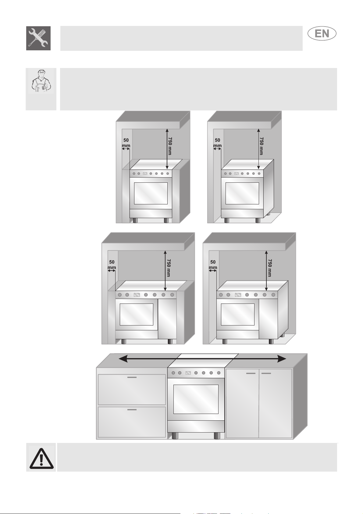
2 INSTALLING THE APPLIANCE
The appliance must be installed by a qualified technician and according to the regulations in force.
Depending on the type of installation, it belongs to class 1 (Fig.A) or to class 2, subclass 1 (Fig.B-C).
This appliance may be installed next to walls, one of which must be higher than the appliance, at a
minimum distance of 50 mm from the side of the appliance, as shown in drawings A and B relative to
the installation classes. Any wall cupboards or ventilation hoods must be at a distance of at least 750
mm above the work surface.
Instructions for the installer
A
Built-in appliance Free-standing installation
A
Built-in appliance Free-standing installation
B
B
C
Appliances equipped with a gas cylinder compartment and electric oven can only be
installed as free-standing (see fig. B).
35
Page 5
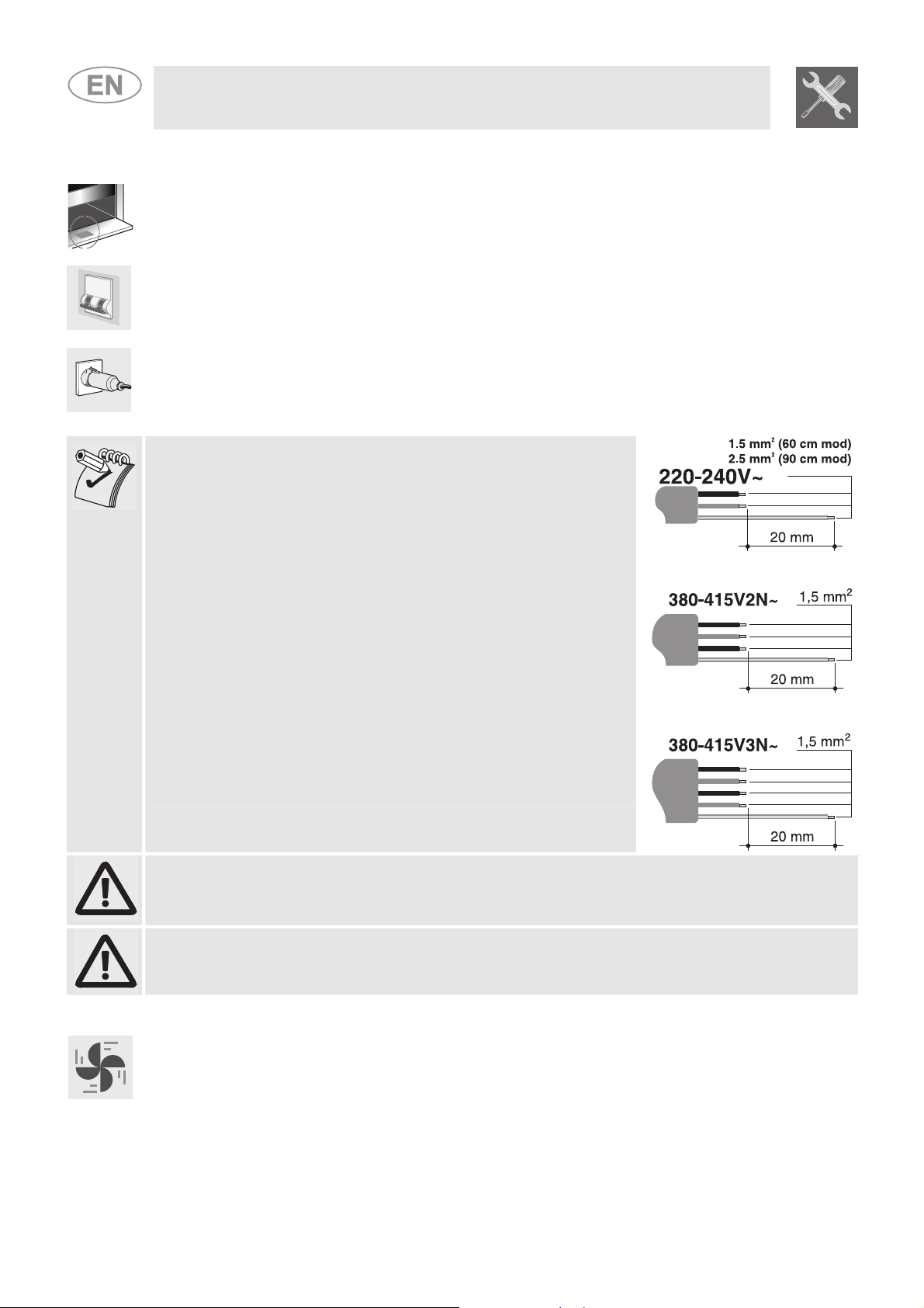
2.1 Electrical connection
Make sure the voltage and the cross-section of the power supply line match the specifications
indicated on the identification plate positioned in the storage compartment.
Do not remove this plate for any reason.
If the appliance is connected to the power supply network by means of a fixed connection, install a
multipolar cut-out device on the power supply line, with a contact opening distance equal to or
greater than 3 mm, located near the appliance and in an easily reachable position.
Connection to the power supply network may be fixed or with a plug and socket. In the latter case
the plug and socket must be suitable for the cable employed and conform to the regulations in force.
Regardless of the type of connection, the appliance must be earthed. Before connection, make sure
that the power supply line is suitably earthed. Avoid the use of adapters and shunts.
1 - For operation on 220-240V∼: use a three-pole cable of the
H05RR-F or H05V2V2-F type:
3 x 2.5 mm2 (for 90 cm models)
3 x 1.5 mm2 (for 50 and 60 cm models).
2 - For operation on 380-415V2N∼ (only for 90 cm models):
use a four-pole cable of the H05RR-F or H05V2V2-F type
(cable with a cross-section of 4 x 1.5 mm2)
3 - For operation on 380-415V3N∼ (only for 90 cm models):
use a five-pole cable of the H05RR-F or H05V2V2-F type
(cable with a cross-section of 5 x 1.5 mm2)
The end to be connected to the appliance must have an earth
wire (yellow-green) at least 20 mm longer than the others.
Instructions for the installer
WARNING: THE VALUES INDICATED ABOVE REFER TO THE CROSS-SECTION OF THE
INTERNAL CONDUCTOR.
Warning: only some of the 90 cm models can be connected with two or three phases.
2.2 Room ventilation
The room containing the appliance should have a permanent air supply in accordance with the
standards in force. The room where the appliance is installed must have enough air flow for the
regular combustion of gas and for the air exchange needed in the room itself. The air vents,
protected by grills, must be suitably dimensioned in compliance with the current regulations and
positioned so that no part of them is obstructed.
The cooker must be kept adequately ventilated in order to eliminate the heat and humidity produced
by cooking: in particular, after prolonged use, you are recommended to open a window or to
increase the speed of any fans.
36
Page 6
Instructions for the installer
Make the connection to the gas mains using a rubber hose whose specifications
2.3 Extraction of the combustion products
The combustion products must be extracted by means of hoods connected to a natural draught
chimney whose efficiency is certain or via forced extraction. An efficient extraction system requires
precision planning by a specialist qualified in this area and must comply with the positions and
distances indicated by the applicable standards. When the job is complete, the installer must issue a
certificate of conformity.
2.4 Connection to gas
2.4.1 Connection with a rubber hose
Installation with a standards-compliant rubber hose must be carried out so that the length of the
piping does not exceed 1.5 metres; make sure that the hose does not come into contact with moving
parts and that it is not crushed in any way. The inside diameter of the hose must be 8 mm for
LIQUID GAS and 13 mm for NATURAL GAS and CITY GAS.
Verify that all the following conditions are met:
• the hose is fixed to the hose connection with safety clamps;
• no part of the hose is in contact with the hot walls (max. 50°C);
• the hose is not under traction or tension and has no tight curves or twists;
• the hose is not in contact with sharp objects or sharp corners;
• if the hose is not perfectly airtight and leaks gas, do not try to repair it: replace it with a new
hose;
• verify that the hose is not past its expiry date (serigraphed on the hose itself).
CONNECTION USING RUBBER HOSES COMPLYING WITH THE CURRENT REGULATIONS IS
ONLY PERMITTED IF THE HOSE CAN BE INSPECTED ALONG ITS ENTIRE LENGTH.
2.4.2 Connection to natural and city gas
comply with the current regulations (verify that the reference standard is stamped
on the hose).
Carefully screw the hose connector A to the gas connector B of the appliance,
placing the seal C between them. Push the rubber hose D onto the hose
connector A and secure it with the clamp E that is compliant with the applicable
standard.
37
Page 7
Instructions for the installer
2.4.3 Connection to the gas cylinder in the internal compartment of the appliance (only on some models)
Open the side compartment and insert a gas cylinder of
max. 15 kg. Push one end of the hose onto the hose
connector and secure it with one of the two clamps
provided. Insert the hose into the gas cylinder
compartment via the hole located at the back of the
appliance following the diagram shown to the side. Push
the other end onto the pressure regulator of the gas
cylinder; secure it in place using the second clamp
provided. Check for any leaks using a soapy solution,
never with a flame.
For the connection between the cooker and the gas cylinder use a piece of standards-compliant
hose no less than 1.4 m in length.
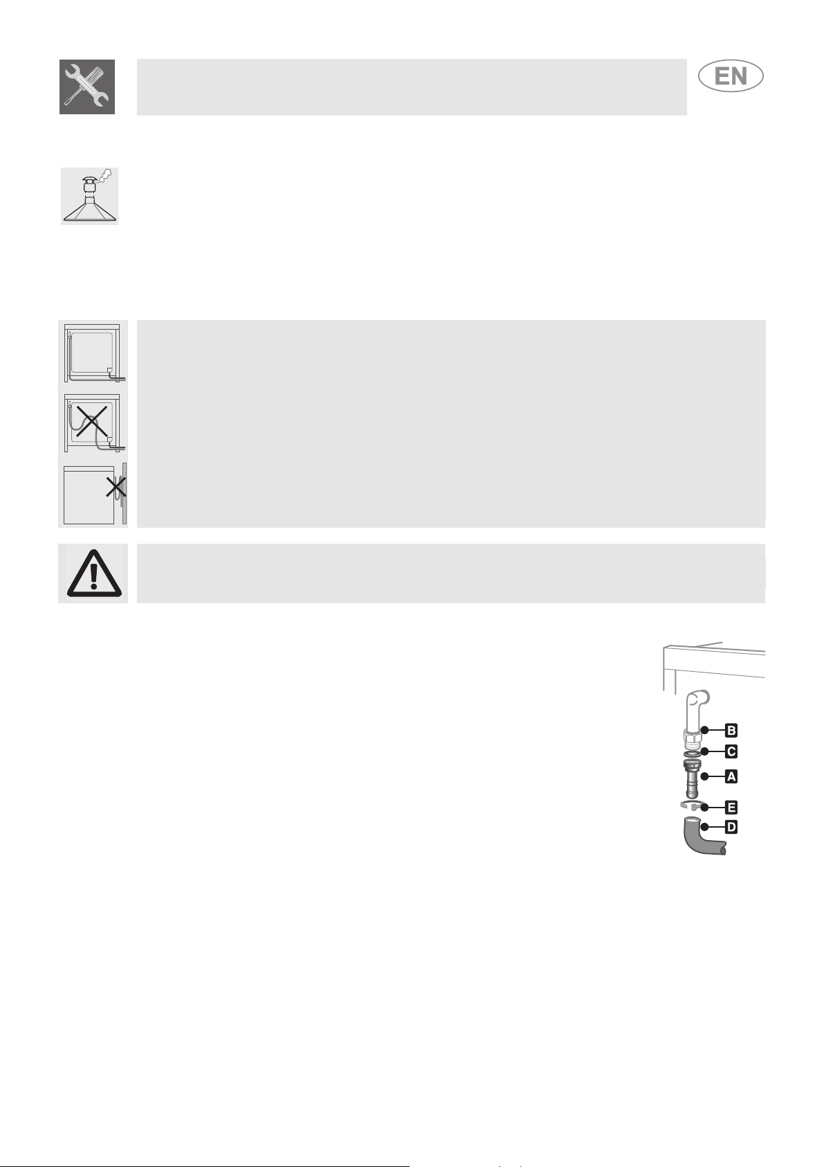
2.4.4 Connection to liquid gas
Use a standards-compliant pressure regulator and carry out the connection to the gas cylinder in
accordance with the regulations in force.
Make sure that the supply pressure complies with the values indicated in the paragraph “3.2/3.3
Burner and nozzle characteristics table”.
Screw the small hose connector F onto the large hose connector A;
connect the block thus obtained to the gas connector B (or use the hose
connector G which must be connected directly to the gas connector B)
and place the seal C in between them. Push the end of the rubber hose
H onto the hose connector A+F (or G) and onto the outlet connection of
the pressure reducer on the gas cylinder. Secure the end of the hose H
to the hose connector A+F (or G) with the standards-compliant clamp I.
The hose connector G illustrated is not supplied with the appliance. Only use standards-compliant
hose connectors.
2.4.5 Connection with a flexible steel hose (for all types of gas)
This type of connection can be made on both built-in and free-standing
appliances. Only use standards-compliant steel hoses whose length is
no greater than 2 metres. Screw the end of the flexible hose L onto the
threaded ½” external gas connector B (ISO 228-1), with the seal C
positioned in between them.
At the end of the installation, check for any leaks with a soapy
solution, never with a flame.
38
Page 8
3 ADAPTATION TO DIFFERENT TYPES OF GAS
Before carrying out the following operations, disconnect the appliance from the electricity supply.
Instructions for the installer
1. Extract the pan racks and remove all the caps and flame-spreader crowns;
The appliance is preset for natural gas G20 (2H) at a pressure of 20 mbar. In the case of operation
with other types of gas, the burner nozzles must be changed and the minimum flame adjusted on the
gas taps. In addition, in the case of the gas oven burner, the primary air must be regulated (3.4.2
Primary air adjustment for the oven burner). To change the nozzles, proceed as described in the
following paragraphs.
3.1 Replacement of the cooking hob nozzles
2. Unscrew the burner nozzles with a 7 mm socket wrench;
3. Replace the burner nozzles according to the gas to be used (see paragraph “3.2/3.3 Burner and
nozzle characteristics table”).
4. Replace the burners in the correct position.
The nozzles for using city gas (G110 – 8 mbar) are available from authorised service centres.
39
Page 9
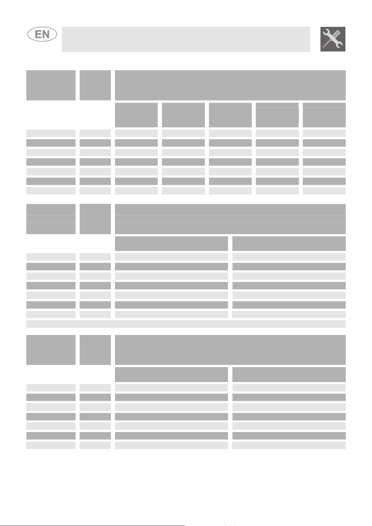
Instructions for the installer
Burner
Auxiliary
Semi-rapid
Rapid (3)
Rapid (5)
Triple crown
Oven
Grill
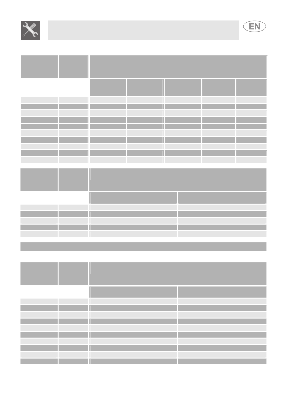
3.2 Burner and nozzle characteristics table (60 cm model)
Rated
heating
capacity
(kW)
1.0 50 30 350 73 71
1.8 65 33 450 131 129
3.0 85 45 800 218 214
2.5 79 45 800 182 179
3.2 91 65 1500 233 229
3.2 87 50 900 233 229
2.9 87 // // 211 207
diameter
1/100 mm
Nozzle
LIQUID GAS – G30/G31 30/37 mbar
By-pass
mm
1/100
Rated
Burner
heating
capacity
(kW)
Auxiliary
Semi-rapid
Rapid (3)
Rapid (5)
Triple crown
Oven
Grill
1.0 145 350
1.8 185 450
3.0 260 800
2.5 230 800
3.5 290 1200
3.2 270 900
2.9 270 //
CITY GAS – G110 8 mbar
Nozzle
diameter 1/100 mm
The values for city gas refer to appliances in category III 1a2H3+.
Rated
Burner
heating
capacity
(kW)
Auxiliary
Semi-rapid
Rapid (3)
Rapid (5)
Triple crown
Oven
Grill
1.0 72 350
1.8 97 450
3.0 115 800
2.5 108 800
3.5 133 1500
3.2 130 900
2.9 130 //
NATURAL GAS – G20 20 mbar
Nozzle
diameter 1/100 mm
Reduced
capacity
(W)
Capacity
g/h G30
Capacity
Reduced capacity
(W)
Reduced capacity
(W)
g/h G31
40
Page 10
Instructions for the installer
Burner
Nozzle
Auxiliary 1 50 30 350 73 71
Semi-rapid 1.8 65 33 450 131 129
Rapid 3 85 45 800 218 214
Triple crown (4) 3.2 91 65 1500 233 229
Triple crown (8) 3.5 94 65 1500 255 250
Fish kettle 1.9 68 45 800 138 136
Oven 3.2 87 50 900 233 229
Maxi oven 5.2 110 59 1300 378 372
Grill 2.9 87 // // 211 207
Maxi grill 4.0 100 // // 291 286
Burner
Nozzle diameter
Auxiliary 1 145 350
Semi-rapid 1.8 185 450
Rapid 3 260 800
Triple crown 3.5 290 1200
Fish kettle 1.9 190 800
Gas G110 cannot be used in gas oven models.
The values for city gas refer to appliances in category III 1a2H3+.
Burner
Nozzle diameter
Auxiliary 1 72 350
Semi-rapid 1.8 97 450
Rapid 3 115 800
Triple crown (4) 3.5 133 1500
Triple crown (8) 3.5 140 1500
Fish kettle 1.9 94 800
Oven 3.2 130 850
Maxi oven 5.2 164 1200
Grill 2.9 130 //
Maxi grill 4.0 150 //
3.3 Burner and nozzle characteristics table (90 cm model)
Rated
heating
capacity
(kW)
Rated
heating
capacity
(kW)
Rated
heating
capacity
(kW)
diameter
1/100 mm
LIQUID GAS – G30/G31 30/37 mbar
By-pass
mm
1/100
CITY GAS – G110 8 mbar
1/100 mm
NATURAL GAS – G20 20 mbar
1/100 mm
Reduced
capacity
(W)
Reduced capacity
Reduced capacity
Capacity
g/h G30
(W)
(W)
Capacity
g/h G31
41
Page 11

3.4 Arrangement of the burners on the hob
Instructions for the installer
BURNERS
1. Auxiliary
2. Semi-rapid
3. Rapid (60 X 60)
4. Triple crown
5. Rapid (60 X 50)
3.5 Arrangement of the burners on the hob
BURNERS
1 Auxiliary
2 Semi-rapid
3 Rapid
4 Triple crown
5 Large electric plate
(1500W)
6 Small electric plate
(1500W)
7 Fish kettle
8 Triple crown
42
Page 12

Instructions for the installer
To adjust the oven burner you need to open the oven door and carry out
3.6 Oven burner adjustment (only for models with a gas oven)
the following operations:
• Remove the oven basin and its rack.
• Lift up the oven surface and pull it outwards.
3.6.1 Replacing the oven + grill burner nozzle
• Loosen the oven burner fixing screw A.
• Push the burner B towards the right until the nozzle
is accessible.
• Using a 13 socket wrench, replace the nozzle,
inserting a new nozzle suitable for the type of gas to
be used (see paragraph “3.2/3.3 Burner and nozzle
characteristics table”).
3.6.2 Primary air adjustment for the oven + grill burner
• Loosen the adjustment screw “A” of the air regulation sleeve.
• Turn the adjustment sleeve “B” to the position that corresponds to the type
of gas to be used according to the table below.
• Tighten the adjustment screw and restore the seals.
• When the operation is completed, reassemble the burner correctly.
OVEN
NATURAL GAS G30/G31 (GPL) G30/G31 (GPL) G 110 – CITY GAS
X =
(N) 60-cm oven 90-cm oven 60-cm oven only
5 mm 10 mm 10 mm 3 mm
GRILL X =
5 mm 15 mm 10 mm 3 mm
43
Page 13

After replacing the nozzles, reposition the flame-spreader crowns, the burner caps and the racks.
4 FINAL OPERATIONS
Following adjustment to a gas other than the preset one, replace the gas adjustment label fixed to
the appliance with the one corresponding to the new gas. The label is inserted inside the pack
together with the nozzles.
4.1 Adjusting the hob burner minimum for city and natural gas
Light the burner and turn it to the minimum position
tap knob and turn the adjustment screw at the side of the tap rod until the
correct minimum flame is achieved.
Refit the knob and verify that the burner flame is stable (when turning the
knob rapidly from the maximum to the minimum position the flame must
not go out). Repeat the operation on all the gas taps.
Instructions for the installer
. Extract the gas
For valved models, keep the knob pressed in at the minimum level for a few seconds to keep the
flame lit and to activate the safety device.
In order to adjust the minimum setting with liquid gas, the screw at the side of the tap rod must be
The oven thermostat is equipped with a screw for regulating the minimum, which can be seen by
4.2 Regulation of the hob burner minimum for liquid gas
tightened clockwise all the way.
The diameters of the by-passes for the individual burners are given in the paragraph “3.2/3.3 Burner
and nozzle characteristics tables”. When the adjustment is completed, restore the sealing of the bypasses with paint or another material.
4.3 Adjustment of the oven burner minimum
removing the thermostat knob.
When changing the type of supplied gas, the minimum must be adjusted as follows:
• Light the oven burner and keep it at the maximum for 10/15 minutes with the door closed and
without the shelf; after this period, move the knob to the minimum temperature, slide off the knob
and insert a straight edge screwdriver to make the adjustment.
• If using liquid gas the adjustment screw must be tightened clockwise to the very end. The
diameter of the by-pass is given in paragraph “3.2/3.3 Burner and nozzle characteristics tables”.
• If using city gas or natural gas, adjust the screw so that when the thermostat knob is turned from
the maximum to the minimum position, the flame remains steady and constant. When the
adjustment is completed, restore the seal on the screws using paint or equivalent materials.
When closing the oven door, make sure the burner remains lit at the minimum.
44
Page 14

4.4 Assembling the skirt (on certain models only)
• Loosen the nuts B.
• Position the skirt above the top, taking care to align the pins C with the holes D.
• Secure the skirt to the top by tightening screws A.
Instructions for the installer
4.5 Positioning and levelling the appliance
After making the electrical and gas connections, level the appliance on the floor by means of its four
adjustable feet. For good cooking results, the appliance must be properly levelled.
Depending on the model you have purchased, the feet height adjustment may vary from 70 to 95
mm and from 110 to 160 mm. These heights refer to the distance between the highest point of the
foot (fixed part) and the lowest point (movable part which rests on the floor).
45
Page 15

All the cooker controls are grouped together on the front panel. The symbols used are described in the
5 DESCRIPTION OF THE CONTROLS ON THE FRONT PANEL
table below.
REAR CENTRAL BURNER ELECTRIC OVEN FUNCTIONS KNOB
FRONT RIGHT-HAND BURNER
REAR RIGHT-HAND BURNER GAS OVEN THERMOSTAT
REAR LEFT-HAND BURNER
FRONT LEFT-HAND BURNER ELECTRIC OVEN THERMOSTAT
Instructions for the user
CENTRAL BURNER
OVEN / ROTISSERIE GRILL LAMP
SWITCH
To light the flame, press the knob and turn it anticlockwise to the minimum
This knob allows the gas burner inside the oven to be lit. The cooking
FRONT CENTRAL BURNER
If the cooker is equipped with an electronic programmer, before using the oven make sure that
appears on the display; see “8.1 Setting the time”.
HOB BURNERS CONTROL KNOB
flame symbol
maximum (
to the
temperature is selected by turning the knob anticlockwise to the desired setting,
between Min. and 275°C.
To learn how to light the gas oven, see the paragraph “
position.
. To adjust the flame, turn the knob to the zone between the
) and minimum ( ) settings. To turn off the burner, turn the knob
GAS OVEN THERMOSTAT KNOB
(ONLY ON MODELS WITH THE RELEVANT FUNCTION)
7.3 Uso del forno a gas”
This knob enables the Grill / Rotisserie function to be activated or the light
inside the oven to be lit to check the cooking progress of the food.
WARNING: IT IS NOT POSSIBLE TO OPERATE THE GAS OVEN AND THE
GRILL / ROTISSERIE AT THE SAME TIME.
OVEN / ROTISSERIE GRILL LIGHT SWITCH KNOB
(ONLY ON MODELS WITH THE RELEVANT FUNCTION)
46
Page 16

Instructions for the user
(ONLY ON MODELS WITH THE RELEVANT FUNCTION)
The cooking temperature is selected by turning the knob clockwise to the
desired setting, between 50°C and 260°C.
The orange light comes on to indicate that the oven is heating up. When this
light goes out, the preset heating temperature has been reached. When the
light flashes regularly it means that the temperature inside the oven is kept
steady on the set level.
(ONLY ON MODELS WITH THE RELEVANT FUNCTION)
The electric oven's various functions are suitable for different cooking modes.
After selecting the desired function, set the cooking temperature using the
thermostat knob.
OVEN LIGHT
STATIC OVEN FUNCTION
ELECTRIC OVEN THERMOSTAT KNOB
STATIC ELECTRIC OVEN FUNCTIONS KNOB
WIDE GRILL FUNCTION
GRILL FUNCTION
LOWER HEATING ELEMENT
FUNCTION
ELECTRIC FAN OVEN FUNCTIONS KNOB
GRILL + ROTISSERIE FUNCTION (IN
MODELS EQUIPPED WITH A
ROTISSERIE)
(ONLY ON MODELS WITH THE RELEVANT FUNCTION)
The electric oven's various functions are suitable for different cooking modes.
After selecting the desired function, set the cooking temperature using the
thermostat knob.
OVEN LIGHT
STATIC OVEN FUNCTION
GRILL FUNCTION
TIMER KNOB
FAN-ASSISTED GRILL FUNCTION
FAN-ASSISTED LOWER HEATING
ELEMENT FUNCTION
FAN OVEN FUNCTION
(ONLY ON MODELS WITH THE RELEVANT FUNCTION)
In order to use the timer, the buzzer must be set by turning the knob in a
clockwise direction. The numbers correspond to minutes (maximum 55
minutes). Adjustment is progressive and intermediate positions between the
figures can be used. The end of cooking buzzer does not interrupt operation of
the oven.
47
Page 17

6 USING THE HOB
6.1 Lighting the hob burners
Before lighting the hob burners, check that the flame-spreader crowns are correctly in place with
their respective burner caps, making sure that the holes A in the flame-spreaders are aligned with
the igniters and thermocouples.
Before lighting the burners, lift the glass lid; before closing it again, turn off all the burners and wait
for them to cool.
The optional rack B is for use with woks.
To prevent damage to the cooking hob, the cooker comes complete with a raised rack C for use
underneath pans more than 26 cm in diameter.
The reduction C supplied is for use with small pans as well.
Instructions for the user
The burner controlled by each knob is shown next to the knob.
The appliance is equipped with an electronic ignition device. Simply press the
knob and turn it anticlockwise to the minimum flame symbol
it does not light in the first 15 seconds, position the knob on 0 and wait at least
60 seconds before trying to light it again.
On valved models, once the burner is lit, keep the knob pressed for a few
seconds to give the thermocouple time to heat up. The burner may go out when
the knob is released: in this case, the thermocouple has not heated up
sufficiently.
Wait a few moments and repeat the operation keeping the knob pressed for
longer. This is not necessary on burners that are not equipped with a
thermocouple.
On models with a thermocouple, if the burners should go out accidentally a safety device will be
tripped, cutting off the gas supply even if the gas tap is open. In this case, turn the knob to the OFF
position and wait at least 60 seconds before trying to light the burner again.
6.2 Practical hints for using the hob burners
For better burner efficiency and to minimise gas consumption: use pans with lids and of a suitable
size for the burner, so that flames do not reach up the sides of the pan (see paragraph “6.3 Pan
Diameters”). Once the contents come to the boil, turn down the flame far enough to ensure that the
liquid does not boil over. To prevent burns or damage to the hob during cooking, all pans or griddles
must be placed inside the perimeter of the hob. All pans must have smooth, flat bottoms. Take the
greatest care when using fats or oils since they may catch fire if overheated. If the flame accidentally
goes out, turn off the control knob and wait at least 1 minute before trying to re-light the burner.
, until it lights. If
48
Page 18

6.3 Pan diameters (60 cm model)
Instructions for the user
6.4 Pan diameters (90 cm model)
BURNERS min. and max.
(60 X 50) (60 X 60)
Ø (in cm)
BURNERS min. and max.
1. Auxiliary 1. Auxiliary 12 – 14 12 – 14
2. Semi-rapid 2. Semi-rapid 16 – 22 16 – 24
5. Rapid
3. Rapid 18 – 24 18 – 26
4. Triple crown 18 – 26
BURNERS
1. Auxiliary
2. Semi-rapid
3. Rapid
4. Triple crown
7. Fish kettle
8. Triple crown
Ø (in cm)
min. and max.
Ø (in cm)
12 – 14
16 – 24
18 – 26
18 – 26
Suitable oval
containers
18 - 26
49
Page 19

6.5 Switching on the electric plate
6.5.1 Switching on electric plates
Instructions for the user
Some models have plates with different diameters. These are controlled by a selector; to switch
them on, turn the knob to the desired position. There is a diagram serigraphed on the front panel
above each knob showing which plate each knob refers to. A red indicator light signals that the
plates have been switched on.
6.5.2 How to use the electric plates
The rapid plates offer the benefit of ultra-rapid cooking. For illustrative purposes only, a regulation
table for the plates is included.
RAPID PLATES
0 Off
1 Dim To melt butter, chocolate etc.
2 Soft To heat up larger amounts of liquid.
3 Slow To thaw frozen foods and to prepare stews, cook
4 Medium To cook foods that have to be brought to the boil;
5
6 High
HEAT INTENSITY
To heat up small amounts of liquid.
at boiling point or just below it.
for delicate meat roasts and fish.
Strong For roasts, chops, steaks and large-scale boiling.
To boil large quantities of water, to fry.
POSSIBLE TYPES OF COOKING
-
PRECAUTIONS
When the plate is switched on for the first time or if it has not been used for a
long time, you must first eliminate any humidity that may have been absorbed
by the insulating coating; to dry it out, leave the plate on for 30 minutes at
position 1 on the selector knob.
For correct use remember:
Only switch on the plate after you have positioned the pan on top of it.
• Use pans with a smooth bottom and a thick base.
• Never use pans that are smaller than the plate.
• Dry the bottom of the pan before putting it down on the plate.
• After use, to keep it in good condition and make sure that the surface is
always clean and shiny, the electric plate must be treated with the
appropriate products that can be bought from shops. This necessary
operation avoids any oxidation (rust).
• When cooking food with oil or fat, which are highly flammable, never leave
the appliance unattended.
• Even after use the plates stay hot for a long time: to avoid getting burned,
do not place your hand or other objects on top of them.
• Before switching on the electric plates, lift the glass cooker lid; before
closing it again, turn off all the plates and wait for them to cool down.
• As soon as you notice a crack on the surface of the plates, immediately
disconnect the appliance from the mains supply and contact the nearest
authorised technical assistance centre.
50
Page 20

Y
Instructions for the user
7.2 Cooling system
Open the oven door fully, press the thermostat knob and turn it anticlockwise to
7 USING THE OVEN
In models with an electronic programmer, before using the oven make sure that is on the display.
In models with an analogue clock and a timer knob, it should be set to .
7.1 Warnings and general advice
Before using the oven and the grill for the first time, pre-heat to their maximum temperature (260°C
for electric ovens and 275°C for gas ovens) long enough to burn away any manufacturing oily
residues which could give the food a bad smell. After an interruption in the electricity supply, the
programmer display flashes
ELECTRONIC PROGRAMMER”.
The oven accessories intended to come into contact with food are made of materials that comply
with the provisions of Directive 89/109/EEC, dated 21/12/88, and of Legislative Decree 108, dated
25/01/92.
WARNING: the gas oven must be lit with the oven door open. The oven is
equipped with a safety system that blocks ignition of the burner if the
door is closed. If you make a mistake in the lighting procedure, open the
oven door and wait a few minutes before trying to light it again.
To prevent any steam in the oven from causing problems, open the door in two
stages: half open (5 cm approx.) for 4-5 seconds and then fully open. If you
need to access the food, always leave the door open for as short a time as
possible to prevent the temperature in the oven from falling and ruining the
food.
DURING THE COOKING OF DESSERTS AND VEGETABLES, DRIPPING FROM THE BOTTOM OF
THE DOOR COULD OCCUR. THIS IS A NATURAL PHYSICAL PHENOMENON WHICH MAINL
OCCURS WHEN PREHEATING HAS NOT TAKEN PLACE. TO AVOID THIS, OPEN THE DOOR A
COUPLE OF TIMES DURING COOKING, TAKING GREAT CARE.
The oven is equipped with a cooling system which automatically comes on a few minutes after the
oven is turned on. The fan causes a steady outflow of air from above the door which may continue
for a brief period of time even after the oven has been turned off.
7.3 Using the gas oven
7.3.1 Electronic spark ignition
the maximum temperature; the electric spark ignition is activated automatically.
When the oven is lit, keep the knob pressed down for a few seconds to allow
the thermocouple to heat up.
If the burner does not ignite after 15 seconds, stop attempting to light it, open
the oven door completely and do not try to light it again for at least 1 minute.
at regular intervals. To make any adjustments, refer to “8
5 cm
7.3.2 Manual ignition
Open the oven door fully and turn the thermostat knob. Bring a lighted
match close to the mouth of flame pipe A at the centre of the oven
surface and press the thermostat knob. Once it is lit, keep the knob
pressed down for a few seconds to allow the thermocouple to heat up
and make sure that it has remained lit by looking through inspection
hole B. The cooking temperature is selected by turning the knob
clockwise to the desired setting, between 50°C and 275°C.
If the burner is extinguished accidentally, turn the knob to the off position ( ) and wait at least one
minute before trying to light it again.
51
Page 21

Thread the support frame onto the second
7.4 Using the electric grill
7.4.1 Using the grill in cookers with an electric oven
For short cooking processes, such as final browning of cooked meat, select the static grill function
and turn the thermostat knob to the maximum temperature setting. The fan-assisted grill function (on
some models only) allows real cooking processes to be carried out, thanks to the forced fan system
that allows the heat to penetrate inside the food. For this type of cooking operation, select the fan-
assisted grill function
cases no more than 200°C).
7.4.2 Using the grill in cookers with a gas oven
To use this function you must first extinguish the oven burner by moving the
relevant knob to the
WARNING: IT IS NOT POSSIBLE TO OPERATE THE GAS OVEN AND THE
GRILL / ROTISSERIE AT THE SAME TIME.
7.4.3 Grill + rotisserie operation (on some models only)
Both the static grill and the fan-assisted grill make it possible to perform cooking processes in
combination with the rotisserie. Insert the rotisserie rod into the rotisserie bushing, select the grill
function
temperature (in any case no more than 200°C).
7.4.4 Using the rotisserie in maxi oven cookers
runner from the bottom so that the rod’s
housing protrudes from the oven. Position the
rod as shown in figure (1) and push the frame
into the oven until the end of the rod lines up
with the rotisserie motor's hole. At this point,
raise the rotisserie rod and push it to the left
until it is in the position illustrated in figure (2).
To activate this function, turn the switch to
posizione
rotisserie operation”).
These operations must be performed with
the oven off and cold.
At the end of cooking, use the tool provided to
slide the rod out of the hole (3) and remove
the frame so that the rotisserie rod can be
taken out of the oven (4).
or or the fan-assisted grill and position the thermostat knob to the desired
(refer to “7.4.3 Grill +
Instructions for the user
and use the thermostat knob to set the ideal cooking temperature (in all
position and then turning the selector to the position.
1
3
2
4
52
Page 22

7.4.5 Using the rotisserie in cookers with a normal oven
Position the rotisserie frame “B” on the
second runner from the bottom and put the
rotisserie rod “A” into the hole in the base of
the oven.
Instructions for the user
How to use the grill
When the oven has come on, confirmed by the red light switching on, leave it to heat up for 5
minutes before placing foods inside.
Food must be seasoned before cooking. Foods should also be coated with oil or melted butter
before cooking. Use the oven tray to collect juice.
The foods to be cooked must be placed on the oven rack, which must then be placed on one of the
runners fitted in the various types of ovens, following the guidelines below:
FOODS
Flat, thin pieces of meat
Rolled roasts
Poultry 2 – 3
PRECAUTIONS
• Grilling processes must never last more than 60 minutes.
• In models with a gas oven, grill and grill + rotisserie cooking must be carried out with the
door partially open to the first click.
• In models with an electric oven, the oven door must be closed during grill and grill +
rotisserie cooking operations.
• To prevent hazardous overheating, the appliance's glass lid must always be raised when
using the oven or grill.
• Accessible parts may be very hot during and after use of the grill; keep children well away
from the appliance.
• During rotisserie cooking operations, one of the trays supplied with the cooker should be
placed on the bottom of the oven, on the first runner from the bottom, to collect any
grease and fat produced.
• When using the oven, remove all unused trays and racks from its interior.
• During cooking, do not cover the bottom of the oven with aluminium or tin foil and do not
place pans or oven plates on it as this may damage the enamel coating. If you wish to use
greaseproof paper, position it so that it does not interfere with the hot air circulation
inside the oven.
If your cooker is equipped with a knob cover, when
cooking with the grill or grill + rotisserie, it should be
mounted as shown in the figure by aligning the slots
“A” with the pins “B” on the upper part of the oven
compartment.
RACK ON THE SHELF
3
2 – 3
53
Page 23

Instructions for the user
7.5 Using the gas grill
7.5.1 Manual ignition of the gas grill burner
Having opened the oven door, press in the knob and turn it clockwise to the grill position , then
bring a lit flame close to the burner on the roof of the oven.
When it is lit, keep the knob held down for about 10 seconds. If the burner does not remain lit after
this period, release the knob and wait for at least 1 minute before making a new attempt to light it. If
the burner goes out accidentally, turn the knob to the off position (
before re-lighting it.
7.5.2 Electrical ignition of the gas grill burner
Having opened the oven door, press in the knob and turn it clockwise to the grill position
When it is lit, keep the knob held down for about 10 seconds. If the burner has not lit after this
period, release the knob and wait for at least 1 minute before making a new attempt to light it. If the
burner goes out accidentally, turn the knob to the off position (
before re-lighting it.
If there is no electrical power, it is still possible to light the burner using matches.
7.6 Storage compartment (on some models only)
The storage compartment is in the bottom of the cooker,
underneath the oven. To open it, pull on the top of the door.
Never use it to store flammable materials such as rags, paper,
etc.; it is intended for storing the appliance's metal
accessories only.
) and wait for at least 1 minute
.
) and wait for at least 1 minute
Do not open the storage compartment when the oven is on and still hot. The temperatures inside it
may be very high.
7.7 Gas cylinder compartment (on certain models only)
The gas cylinder compartment, accessed by opening the side
door, can also be used as a storage space.
The 3 racks in the figure are not supplied with the appliance
but can be purchased on request from Authorised Service
Centres.
54
Page 24

8 ELECTRONIC PROGRAMMER (ONLY ON MODELS WITH THE
Instructions for the user
RELEVANT FUNCTION)
8.1 Setting the time
When the oven is used for the first time, or after an interruption in the electricity supply, the display
flashes at regular intervals, showing
time press the value adjustment buttons
minute for each pressure.
Press one of the two value modification buttons until the current time appears.
Before each programmer setting, activate the desired function and temperature.
8.2 Semi-automatic cooking
This function only switches the oven off automatically at the end of the cooking time. Press the
button and the display will light up showing the figures
use the value modification buttons
When the
display will show the current time together with the symbols A and
8.3 Automatic cooking
This function switches the oven on and off in fully automatic mode.
Press the
same time use the value modification buttons
Press the
keep it pressed, and at the same time use the value modification buttons
of cooking time.
When the
current time together with the symbols A and
After making the setting, press the button to view the remaining cooking time; press the button
to view the cooking end time. The logic prevents the setting of incompatible values (e.g. the timer will
not accept a cooking end time with a duration which is too long for its value).
LIST OF FUNCTIONS
TIMER BUTTON
COOKING DURATION BUTTON
END OF COOKING BUTTON
VALUE DECREASE BUTTON
VALUE INCREASE BUTTON
. Press the and buttons together, and at the same
or : this will increase or decrease the setting by one
; keep it pressed, and at the same time
or to set the cooking duration.
button is released, the count of the programmed cooking duration will start and the
.
button and the display will light up showing the figures ; keep it pressed, and at the
or to set the cooking duration.
button and the display will show the sum of the current time plus the cooking duration:
or to adjust the end
button is released, the programmed count will start and the display will show the
.
55
Page 25

8.4 End of cooking
At the end of the cooking time the oven will switch off automatically and simultaneously a buzzer will
start to sound intermittently.
After the buzzer has been deactivated, the display will return to show the current time together with
the
symbol to indicate that the oven has returned to manual use mode.
8.5 Timer
The programmer can also be used as an ordinary timer. Press the button and the display will
show the figures
. When the button is released, the programmed count will start and the display will show the
current time and the symbol
After the setting, to display the time left press the button.
In timer mode, the system will not cut out operation of the oven at the end of the set time.
Instructions for the user
; keep it pressed and simultaneously press the value modification buttons or
.
8.6 Adjusting the buzzer volume
The buzzer has 3 different volume settings.
To modify it, press the
button at the end of the timer function when the buzzer is in operation.
8.7 Stopping the buzzer
The buzzer stops automatically after seven minutes. It can be stopped manually by pressing the
and
buttons together. To switch off the oven, return all the knobs to the 0 setting in
sequence.
8.8 Deleting the set data
With the program set, hold down the button of the function to be deleted, while at the same time
going to the value
by pressing the value modification buttons and . The programmer will
interpret deletion of the duration as the end of cooking.
8.9 Modifying the set data
The set cooking data can be modified at any time by holding down the button of the function for
modification and at the same time pressing the value modification buttons
or .
56
Page 26

Instructions for the user
9 DIGITAL TIMER (ONLY ON MODELS WITH THE RELEVANT
FUNCTION)
This component indicates the preset end of cooking time by means of an intermittent buzzer. It
therefore only fulfils the function of a timer, not a programmer.
LIST OF FUNCTIONS
CLOCK SETTING BUTTON
VALUE DECREASE BUTTON
VALUE INCREASE BUTTON
9.1.1 Setting the time
When the oven is used for the first time, or after an interruption in the electricity supply, the display
flashes at regular intervals, showing
time.
9.1.2 Setting the timer
To set the timer, press and hold down
. Press and use or to set the clock to the current
until the desired number of minutes is reached. Release
and the countdown will start about 5 seconds later; once the countdown is complete, an intermittent
buzzer will be activated.
During the countdown,
for 5 seconds.
9.1.3 Stopping the buzzer
The buzzer stops automatically after seven minutes. It can be deactivated manually by pressing .
9.1.4 Adjusting the buzzer volume
The buzzer volume can be varied (3 settings) while it is in operation by pressing .
9.1.5 Modifying the set data
The set data for the timer can be modified at any time by pressing or .
10 ANALOGUE CLOCK (ONLY ON MODELS WITH THE RELEVANT
will appear on the display and you can press to show the current time
FUNCTION)
The mechanical timer can be set by turning the knob clockwise.
Minutes can be set from 0 to 55. When cooking is complete, a buzzer will
sound: to deactivate it, turn the outside part to
The clock can be set by pulling out and turning the knob clockwise.
using the knob.
57
Page 27

Instructions for the user
11 CLEANING AND MAINTENANCE
11.1 Cleaning stainless steel and enamelled versions
To keep stainless steel in good condition, it must be cleaned regularly when you have finished using
the cooker, after it has cooled.
Do not use a steam jet for cleaning the appliance.
11.1.1 Ordinary daily cleaning
To clean and preserve the stainless steel surfaces, always use only specific products that do not
contain abrasives or chlorine-based acids.
How to use: pour the product onto a damp cloth and wipe the surface, rinse thoroughly and dry with
a soft cloth or chamois leather.
11.1.2 Food stains or residues
Do not use metallic sponges or sharp scrapers as they will damage the surface.
Use normal non-abrasive products and a wooden or plastic tool if necessary. Rinse
thoroughly and dry with a soft cloth or chamois leather.
Do not allow residues of sugary foods (such as jam) to set inside the oven. If left to set
for too long, they might damage the enamel lining of the oven.
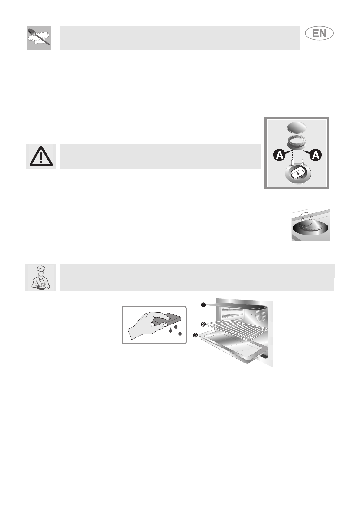
11.2 Cleaning the cooking hob's parts
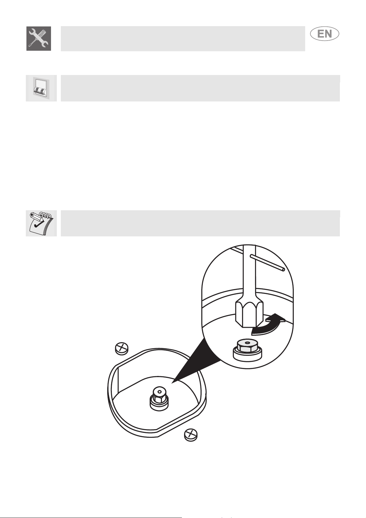
11.2.1 Glass lid
For easier cleaning, the lid can be extracted from its hinges.
1- position it in the open position;
2- unscrew the screws positioned on the back of the two hinges (indicated
by the arrows in the figure) and lift it upwards.
If liquids fall on the lid when it is closed, carefully remove them with a cloth
before opening it.
To replace the lid, insert it into the guides and tighten the fixing screws of
the hinges in the open position.
58
Make sure never to touch the lid glass with pots and pans that are still hot. The glass could crack
and break with the heat.
Page 28
Instructions for the user
For easier cleaning, the flame-spreader crowns can be removed; wash
11.2.2 Racks
Remove the racks and clean them with lukewarm water and non-abrasive detergent, making sure to
remove any encrustations. Replace them on the cooking hob.
Continuous contact between the racks and the flame can cause modifications to the enamel over
time in those parts exposed to heat. This is a completely natural phenomenon which has no effect on
the operation of this component.
11.2.3 Burner caps and flame-spreader crowns
them with warm water and a non-abrasive detergent making sure to
remove any encrustation and wait until they are perfectly dry.
WARNING: never wash these parts in a dishwasher.
They can be left to soak in warm water and detergent.
Replace the flame spreader crowns, making sure that they are correctly
in place with their respective burner caps and ensuring that the holes A
in the flame-spreaders are aligned with the igniters and thermocouples.
11.2.4 Igniters and thermocouples
For correct operation, on those models that have them, the igniters and
thermocouples must always be perfectly clean. Check them frequently and clean
them with a damp cloth if necessary. Remove any dry residues with a wooden
toothpick or a needle.
11.3 Cleaning the oven
For the best oven upkeep, clean it regularly after having allowed it to cool. Take out all removable
parts.
Clean the oven racks with warm water and non-abrasive detergent. Rinse and dry.
11.4 Door glazing
The glass in the door should always be kept thoroughly clean. Use absorbent kitchen roll; remove
stubborn dirt with a damp sponge and an ordinary detergent.
59
Page 29

Instructions for the user
12 EXTRAORDINARY MAINTENANCE
The oven may require extraordinary maintenance or replacement of parts subject to wear such as
gaskets, bulbs, etc. The following instructions describe how to carry out these minor maintenance
operations.
Before any intervention that requires access to live parts, disconnect the power supply of the
appliance.
12.1 Lubrication of gas oven taps and thermostat knob
Over time the gas taps and the thermostat knob may become difficult to turn and get blocked. Clean
them internally and replace the lubrication grease.
This operation must be carried out by a specialised technician.
12.2 Changing the light bulb
Remove the bulb protector A by turning it anticlockwise and replace bulb B with a similar one (25
W). Re-fit the bulb protector A.
Use oven bulbs only (T 300°C).
12.3 Removing the door
Lift the levers B and take hold of the two sides of the
door with both hands near the hinges A. Raise the door
to an angle of about 45° and remove it. To reassemble,
fit the hinges A into their grooves, then lower the door
into place and release the levers B.
12.4 Removing the door seal
To permit thorough cleaning of the oven, the seal may be removed.
Before removing the seal, take off the door as described above. Once the
door has been taken off, lift the tabs at the corners as shown in the figure.
60
Page 30

Page 31

914772033/ E
 Loading...