

Page 1
LAVABICCHIERI PROFESSIONALI
PROFESSIONAL GLASSWASHERS
LAVE-VERRES PROFESSIONNELS
PROFESSIONELLER GLÄSERSPÜLER
LAVAVASOS PROFESIONAL
MÁQUINAS DE LAVAR COPOS PROFISSIONAL
CW350B CW350BS CW350BSD
CW350 CW350S CW350SD
CW400B CW400BS CW400BSD
CW400R CW400RS CW400RSD
Page 2
1 Safety and usage instructions
2 Technical characteristics
3 Installation and positioning
4 Installer – technical assistant instructions
5 First startup
6 Settings
7 Screen-displayed anomalies (technical)
8 User instructions Mod. CW400R – CW400RSD
9 User Instructions Mod. CW350B-CW350BSD-CW350-CW350SD-
CW400B-CW400BSD
10 Maintenance and cleaning
11 Problems and anomalies (user)
12 Screen-displayed anomalies (user)
13 Electrical - Connections scheme
Thank you for having chosen this product.
We recommend that you read all of the instructions contained in the manual attentively in order to become
familiar with the most suitable conditions for the correct use of the dishwasher.
TECHNICAL INSTRUCTIONS:
Are intended for qualified personnel who will perform the installation, the setup, the testing
and eventual assistance operations.
USER INSTRUCTIONS:
Indicate the recommended usage, the command descriptions and the proper cleaning and
maintenance operations for the dishwasher.
Page 3
1 Safety and usage instructions
THIS MANUAL CONSTITUTES AN INTEGRAL PART OF THE DISHWASHER; IT MUST
NECESSARILY BE STORED INTEGRAL AND TOGETHER WITH THE APPARATUS.
THE DISHWASHER IS INTENDED EXCLUSIVELY FOR PROFESSIONAL USE AND MUST BE USED BY
COMPETENT PERSONNEL. IT IS DESIGNED TO WASH DISHES (PLATES, CUPS, BOWLS, BAKING
PANS, SILVERWARE) AND SIMILAR ITEMS FROM THE GASTRONOMY AND THE COLLECTIVE
RESTAURANT INDUSTRIES. IT CONFORMS TO THE INTERNATIONAL ELECTRIC AND MECHANICAL
SAFETY NORMS (CEI-EN-IEC 60335-2-58/61770) AND ELECTROMAGNETIC COMPATIBILITY NORMS
(CEI-IEC-EN 55014-1/-2, 61000-3;4, 50366).
THE MANUFACTURER DECLINES ANY RESPONSABILITY FOR DAMAGE TO PERSONS OR THINGS
CAUSED BY NON-OBSERVANCE OF THE INSTRUCTIONS PRESENT IN THE MANUAL, BY INCORRECT
USE, BY TAMPERING EVEN WITH A SINGLE PART OF THE APPARATUS AND BY USE OF NONORIGINAL REPLACEMENT PARTS.
THIS APPARATUS IS MARKED IN CONFORMITY TO THE EUROPEAN DIRECTIVE 2002/96/EC, WASTE
ELECTRICAL AND ELECTRONIC EQUIPMENT (WEE).
BY ENSURING THAT THIS PRODUCT BE DISPOSED OF IN A CORRECT MANNER, THE USER
CONTRIBUTES TO THE PREVENTION OF POTENTIALLY NEGATIVE ENVIRONMENTAL AND HEALTH
CONSEQUENCES.
THE
THAT THIS PRODUCT MUST NOT BE TREATED AS DOMESTIC WASTE, BUT MUST BE TAKEN TO A
SUITABLE COLLECTION DEPOT FOR THE RECYCLING OF ELECTRIC AND ELECTRONIC APPARATUS.
DISPOSE OF THE APPARATUS ACCORDING TO THE LOCAL WASTE DISPOSAL NORMS.
FOR MORE INFORMATION ON THE TREATMENT, RECOVERY AND RECYCLING OF THIS PRODUCT,
CONTACT YOUR COMPETENT LOCAL AUTHORITY, YOUR DOMESTIC WASTE DISPOSAL SERVICE OR
THE STORE IN WHICH THE PRODUCT WAS PURCHASED.
THE POSITIONING, CONNECTIONS, SETUP AND TROUBLESHOOTING, AND THE
SUBSTITUTION OF THE POWER CABLE MUST BE PERFORMED BY QUALIFIED
PERSONNEL.
THE ELECTRICAL GROUNDING OF THE APPARATUS ACCORDING TO THE METHODS
PRESCRIBED BY THE ELECTRICAL SYSTEM’S SAFETY NORMS IS OBBLIGATORY.
SYMBOL ON THE PRODUCT, OR UPON ITS ACCOMPANYING DOCUMENTATION, INDICATES
DO NOT INSERT SOLVENTS SUCH AS ALCOHOL OR TURPENTINE WHICH COULD
PROVOKE EXPLOSIONS. DO NOT INSERT DISHES WITH RESIDUES OF ASH, WAX OR
VARNISH.
NEVER USE THE DISHWASHER OR ITS PARTS AS A STEP-LADDER, SUPPORT OR BRACE
FOR PERSONS, THINGS OR ANIMALS.
LEANING OR SITTING UPON THE DISHWASHER’S OPEN DOOR COULD CAUSE IT TO TIP,
WITH CONSEQUENT PERSONAL DANGER.
DO NOT LEAVE THE DISHWASHER’S DOOR OPEN IN ORDER TO AVOID TRIPPING UPON
IT.
DO NOT DRINK THE RESIDUAL WATER EVENTUALLY PRESENT IN THE DISHES OR IN THE
DISHWASHER AFTER A WASH CYCLE.
THE APPARATUS IS NOT ADAPTED FOR USE BY MINORS AND PEOPLE WITH REDUCED
PHYSICAL, SENSORIAL OR MENTAL CAPABILITIES WITHOUT EXPERIENCE OR
FAMILIARITY WITH THE DEVICE. THE USE OF THE APPARATUS IS PERMITTED TO THESE
PEOPLE ONLY UNDER THE SUPERVISION OF A PERSON IN CHARGE OF THEIR SAFETY.
2
Page 4
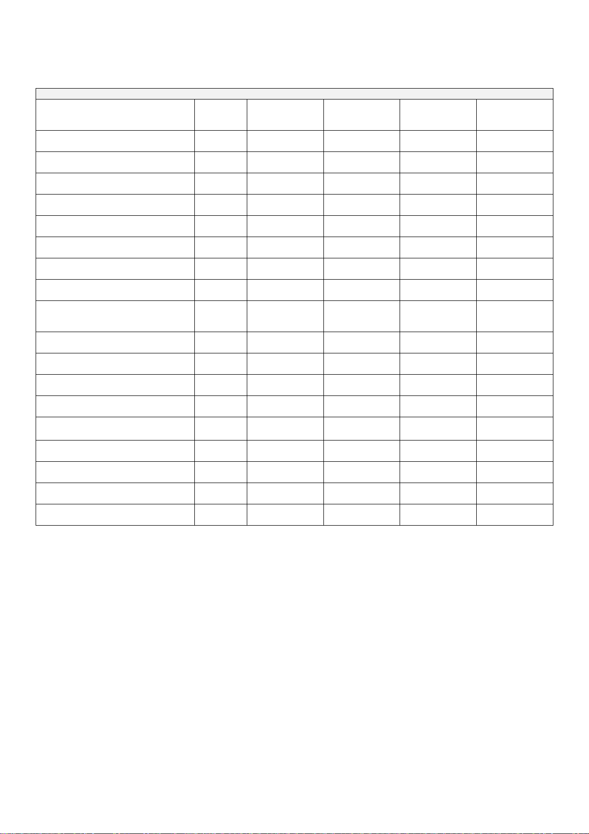
2 Technical characteristics
Input voltage power V 230V/1 230V/1 230V/1 400V 3N ~
Frequency Hz 50 50 50 50
Max. absorbed power kW 2,9 2,9 2,9 4,8
Boiler resistance power kW 2,6 2,6 2,6 4,5
Tank resistance power kW 1,6 1,6 1,6 1,6
Wash pump power kW 0,3 0,3 0,3 0,3
TECHNICAL CHARACTERISTICS
CW350B
CW350BS
CW350BSD
CW350
CW350S
CW350SD
CW400B
CW400BS
CW400BSD
CW400R
CW400RS
CW400RSD
Water supply pressure
Water supply temperature
“S” versions Water supply
temperature (incorporated watersoftener)
Water supply hardness
Rinse cycle water consumption
Boiler capacity
Tank capacity
Standard cycle duration with
water supply at 50°C
Noise level
Protection rating
Net weight
Power cable type
kPa (bar) 200-400 (2 ÷ 4) 200-400 (2 ÷ 4) 200-400 (2 ÷ 4) 200-400 (2 ÷ 4)
°C 50°C – 60°C 50°C – 60°C 50°C – 60°C 50°C – 60°C
°C 15°C – 30°C 15°C – 30°C 15°C – 30°C 15°C – 30°C
°dF 7°dF-12°dF 7°dF-12°dF 7°dF-12°dF 7°dF-12°dF
l 2,4 2,4 2,4 3,5
l 2,7 2,7 3,9 5,5
l 10 10 14 35
s 120/180 120/180 120/180 60/120/180/C
dB(A) 56 56 56 56
IPX 4 4 4 4
kg 31 37 44 53
◄HAR► H05VV-F H05VV-F H05VV-F H07RN-F
NOTE: “D” = versions with integrated detergent metering unit – “S” versions with integrated
water-softener
3 Installation and positioning
INSTALLATION and POSITIONING
Bring the dishwasher to its installation location, remove its packaging and verify the integrity of the apparatus
and of the components. If damaged, written notification must be sent to the transporter.
The packaging elements (plastic bags, polystyrene foam, nails, etc) must not be left within reach of children
and domestic animals as they are a potential source of danger.
All of the materials used for packaging are compatible with the environment. They may be safely preserved, or
may be disposed of at an appropriate waste disposal facility.
The components in plastic material subject to eventual disposal through recycling are marked in the following
manner:
PE polyethylene: external wrapping, instructions bag, protection bags.
PP polypropylene: bands.
PS polystyrene foam: protective corners, packaging cover.
3
Page 5
The wood and cardboard components can be disposed of by respecting the norms in vigor.
When disposing of the product, avoid leaving it in the environment; its disposal must respect the norms in vigor.
All of the metallic parts are in stainless steel and are detachable.
The plastic parts are marked with the symbol of the relative material.
POSITIONING:
Warning:
must answer to the norms in vigor.
The manufacturer declines any responsibility for direct damages to persons of things deriving from lack of
respect for the said norms.
Prior to installation verify that objects and materials which could be damaged by aqueous vapor or by spray
from washing solutions are not in the vicinity, or are adequately protected.
Position the dishwasher in the desired position and remove the protective wrapping.
Level the dishwasher (with the help of a level) on its four feet, regulating them in such a way so as to
guarantee stability; any alternate solution must be approved by the manufacturer.
the internal system and the locations in which communal apparatus are to be installed,
4 INSTALLER – TECHNICAL ASSISTANT
INSTRUCTIONS
Water and drain connection:
The water tubes and the electrical power cable stick out from the back of the machine. Connect the water
supply tube to a ¾” threaded gas outlet.
Use only new tubes for the connection to the water supply; old or used tubes must not be utilized.
The dynamic supply pressure must be between 2 and 4 bar; if the pressure is higher, a pressure reducer
must be installed.
It is indispensable to install a general faucet on the supply water input tubing; the faucet must be accessible
after installation has been completed. Do not install the faucet behind the dishwasher.
The declared cycle durations refer to a 50° hot water supply.
Where a cold water supply is used, the duration of the cycle could increase in relation to the input water
temperature since the dishwasher is equipped with a constant temperature and pressure rinse system.
Drain:
Every dishwasher comes equipped with a drain connection tube; this is prescribed to be at floor level, with a
trap drain.
Caution: make sure that the supply and drain tubes are not bent, restricted or crushed after
installation.
4.1 Electrical connection
The dishwasher’s electrical connection and that of eventual supplementary apparatus is to be
entrusted to authorized and qualified personnel, with respect to the norms in vigor; observe also the
technical regulations for the connections.
The total power installed is given upon the apparatus’ technical data label.
Other apparatus must not be protected along with the dishwasher.
The user must provide for the installation, according to the norms in vigor, of a main electrical power
switch and of a differential switch compatible with the machine’s characteristics.
These switches must be installed near the dishwasher, be easily accessible after installation and
guarantee complete disconnection from the electrical supply in category III overvoltage conditions.
Caution!!!
The dishwasher is free of electrical current only when the main switch is off.
‐ Connect the apparatus to the usage equalizer. The
clamp for the connection is located at the lower
4
Page 6
back of the machine.
‐ The protection conductor (PE) is yellow-green in color, the neutral conductor (N) is blue and the
phase conductors (L1, L2, L3) are black, gray and brown.
5 FIRST STARTUP
FIRST STARTUP
The electrical protection system must be subjected to a functional test before use. The installation must be
performed and/or verified by the authorized reseller who will be responsible for the first startup and the
instructions relative to the dishwasher’s operation.
PREPARATION FOR USE
Important:
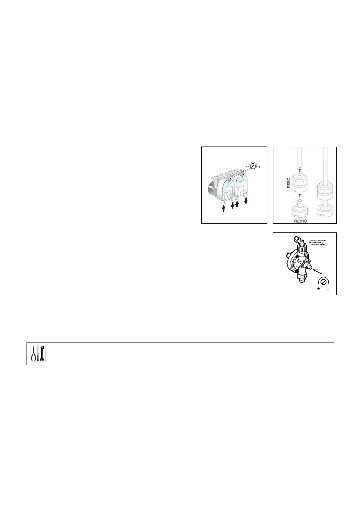
The rinse-aid metering unit comes equipped in all models
while the detergent metering unit comes equipped in only
some models.
If both metering units are present position the external
detergent and rinse-aid containers and insert their
respective suction tubes located at the back of the machine.
Red tube: detergent
Transparent tube: rinse-aid
Before inserting the tubes in the containers apply the weight
(necessary to keep the tube at the bottom of the container)
and the filter as indicated in the diagram.
For adjustments, use the adjustment screws indicated in the diagram. It is
recommended that adjustments be performed by personnel from the companies who
have supplied the detergent products.
If the detergent metering unit did not come pre-installed it can be installed at a later
time by ordering the relative KIT.
Alternatively, an external metering unit can be connected by means of an electrical
connection with a 2x0.5 mm type H05 RN-F cable. This cable must be inserted through
the passage indicated in the TECHNICAL CHARACTERISTICS scheme and
connected in accordance with the electrical scheme furnished with the dishwasher.
The metering unit must be of 230V/50Hz with a maximum absorbed power of 15W.
Connect the detergent metering unit to the dishwasher through the red tube cited above.
6 SETTINGS (only models CW400RSD - CW400R – CWC500R)
SETTINGS
During the first startup, arrange for the setup or the adjustment of the functions/parameters indicated
hereafter:
POWER SUPPLY: 200 – 250 VAC.
ABSORBED POWER : 4 VA
OPERATIONAL TEMPERATURE: 0 / 60 °C
OPERATIONAL HUMIDITY: max 90 % without condensation
NORMS: The control unit is designed and manufactured in observance of the
European norms in vigor regarding electrical safety and electromagnetic compatibility.
Particularly the following:
EN 61000-6-3 : Emissions for residential and commercial environments
EN 61000-6-2 : Immunity for industrial environments
EN 61000-4-11 : Immunity to supply micro-interruptions
EN 60335-1 : Low voltage safety directive
5
Page 7
ZERO CROSSING : The relay which powers the Tank’s electrical resistance is equipped with the “ zero crossing “
function which synchronizes the switching of this relay, both in closing and in opening, with the voltage supply’s
passing to zero both for 50 Hz and 60 Hz frequencies. In this manner the relay’s contacts usage is significantly
reduced.
CONNECTION SCHEME
Clamp Connection for model. CWC500R Connection for models CW400RSD – CW400R
1 – 2 CONTROL UNIT POWER SUPPLY, 230 VAC CONTROL UNIT POWER SUPPLY, 230 VAC
3 – 4 BOILER TEMPERATURE SENSOR BOILER TEMPERATURE SENSOR
5 – 6 TANK TEMPERATURE SENSOR TANK TEMPERATURE SENSOR
10 BREAK-TANK PRESSOSTAT BREAK-TANK PRESSOSTAT
11 Reserve input SALT CONTAINER SENSOR
12 MICRO HOOD MICRO DOOR
13 TANK PRESSOSTAT, closed over level TANK PRESSOSTAT, closed over level
14 COMMON INPUTS COMMON INPUTS
15 BOILER RESISTANCE REMOTE CONTROL SWITCH COIL BOILER RESISTANCE REMOTE CONTROL SWITCH COIL
16 TANK RESISTANCE, max. 10 Amp. TANK RESISTANCE, max. 10 Amp.
17 - REGENERATION ELECTROVALVE
18 - COLD RINSE ELECTROVALVE
18 B.TANK RINSE PUMP (MACHINE TYPE 4) RINSE PUMP (MACHINE TYPE 4)
19 WASH PUMP ( max. 1 HP ) WASH PUMP ( max. 1 HP )
20 RINSE ELECTROVALVE + PRESSURE INCREASE PUMP RINSE ELECTROVALVE + PRESSURE INCREASE PUMP
21 DRAIN PUMP ( max. 0.75 HP ) Optional DRAIN PUMP ( max. 0.75 HP ) Optional
22 OUTPUT POWER SUPPLIES, 230 VAC phase OUTPUT POWER SUPPLIES, 230 VAC phase
6
Page 8
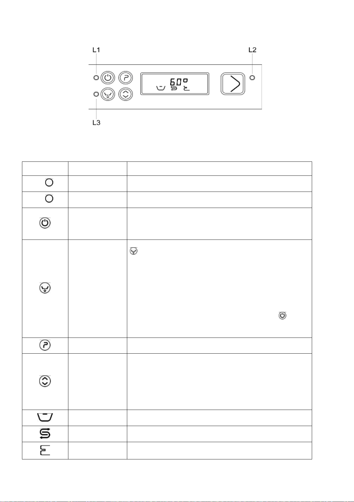
KEYBOARD FUCNTIONALITY CW400RSD – CW400R
MAIN FUNCTIONS WITH MACHINE POWERED
ITEM Description Function
L1
L2
Machine powered
led indicator
Tank emptying led
indicator
On/Off button
Tank emptying
button
Programs button
OPTIONS button
Tank led indicator
Salt led indicator
This led indicator turns on (green) when electrical current is present
This led indicator (green) indicates that the machine is emptying the
Tank – the led flashes when the operation is in progress.
Pressing this button with led indicator 1 on activates the keyboard
and renders the machine operational.
The last program used (wash cycles) will be shown on the 3
displays when turned on.
To empty the Tank first remove the Tank’s overflow, then press the
button for 3 seconds. This inhibits water from being loaded and,
after a Pressostat Tank-empty signal verifies that the Tank has
been emptied, will only allow a limited amount of boiler water to
circulate in order to facilitate the cleaning of the Tank.
At the end of the function the machine goes into a stand-by phase
which is indicated by the appearance of three dashes “---“ upon the
displays. To render the machine operational again it is therefore
necessary to insert the Tank’s overflow and to press the
If the machine is equipped with the drain pump option, the drain
pump will also be activated.
By repeatedly pressing this button the various wash cycles can be
viewed (brief 60”, medium 120”, long 180”, continuous)
The use of this button does the following, in sequence:
• Enables the “crystal cycle” only with the medium cycle 120”
(“C” on the display”); Sets the T of the boiler from 85°C to
70°C
• Enables regeneration (rig on the display) if decal is
installed. (if a program has not been set, it will not be
performed)
Indicates, when on, that the temperature shown during washing is
that of the Tank.
Indicates insufficient salt quantity (if prescribed in the function)
The led indicator turns on for the closing of a reed contact.
button.
7
Boiler led indicator Boiler resistance in function symbol
Page 9
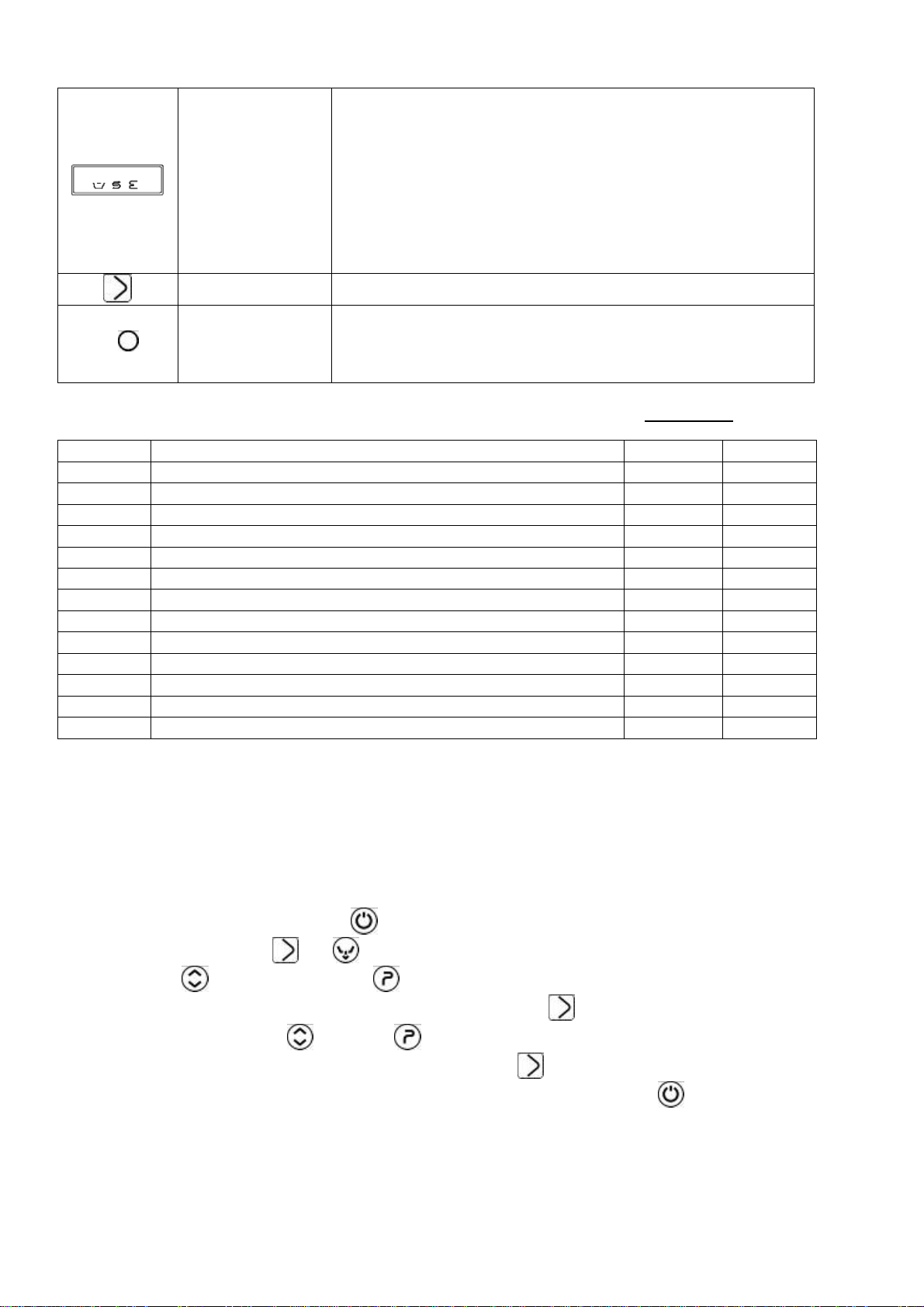
Can indicate the program which will begin and the boiler/Tank
temperature.
In case of anomalies an error code will be indicated, for example
“E 1”
3 DISPLAY
L3
MACHINE CONFIGURATION PARAMETERS (Intended for technical personnel, not the user
Parameter Description Range Preset
P0 Drain cycle time 1-5’ 1
P1 Boiler temperature 60-95°C 82
P2 Tank temperature 40-65°C 55
P3 Rinse duration 10-40’’ 13
P4 BOILER STOP option YES/NO 1 YES
P5 Brief wash time 60-90 60
P6 Drain with overflow option YES/NO 1 YES
P7 Cold rinse option YES/NO 0 NO
P8 Regeneration option YES/NO 1 YES
P9 Maximum water load duration 1-10’ 10
P10 H2O Hardness (to be set by the user based on water hardness) 35 15
P11 Machine type 4 4
P12 Wash number counter YES 1 YES
Start button Initiates the program shown on the display
Bicolor led indictor
- Boiler temperature anomaly
- Tank temperature anomaly
- Tank loading anomaly
- Tank draining anomaly
- Boiler anomaly
This led indicates the state of the machine
• Green indicates the machine is ready for a new program
• Red indicates the machine is busy with an operation
• Yellow indicates a break after Tank draining
)
PARAMETER FUNCTION WITH MACHINE ON
Upon first installation it is possible to perform a series of operations which allow for the personalization of the
dishwasher based on the user’s necessities, as well as a test cycle which quickly checks the functionality of all of
the components. To perform these operations it is necessary to set the machine to “programming mode” as
described hereafter
‐ Shut the machine off by pressing
‐ Simultaneously press
‐ With the
‐ Once the parameter to modify has been identified, keep the
setting with the “ahead”
‐ Once the setting has been correctly modified, release the
‐ When finished with the settings turn the machine off and on again by pressing
Note: always turn on the DRAIN PUMP function in machines with Air Tank or Break Tank even if absent.
IN PARAMETERIZATION MODE, IF NO BUTTON IS PRESSED WITHIN 30 SECONDS THE KEYBOARD SHUTS
DOWN AND RETURNS TO ITS OFF STATE.
button (ahead) and the button (back) select the programs
and until P0 appears on the display
and “back” buttons
button pressed and modify the required
button
8
Page 10
Regeneration mode:
Once having reached the set number of cycles, at the end of the last cycle (ex. The 20
message rig will appear flashing on the display for 10”; of it is desired to continue and the request is ignored, the
message will appear for 10” at the end of every cycle.
The regeneration phase only begins after the Tank Pressostat has arrived at empty
1) EVR active for 20”, 1’ break – repeat EV regenerate activation 4 times
2) 8’ break
3) EV1 active for 25”, 1’ break - repeat EV load activation 4 times, PS activation (drain pump) contextually to EV
load + 5”
Afterwards, once the first samples are available, verify the correctness of the times/actual regeneration and proper
resin washing.
At the end of the regeneration, the display goes back to showing the last program performed and the machine is
once again ready for use.
Note: the regeneration cycle can be cancelled once initiated by keeping the
th
or the 35th, etc.) the
button pressed for 10 seconds.
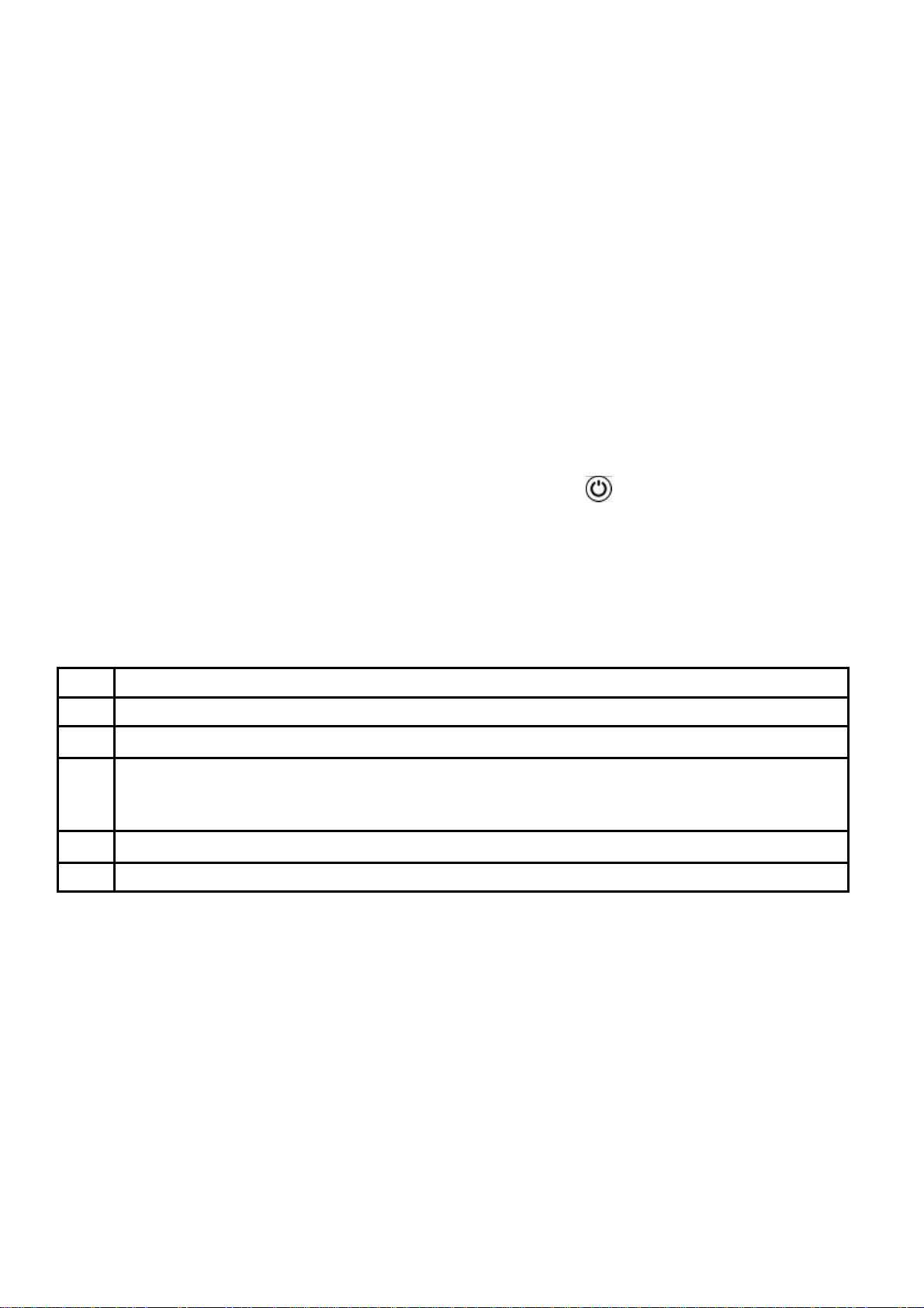
7 SCREEN DISPLAYED ANOMALIES
After having turned the machine off and on again, if the problem persists communicate the type of error displayed
on the screen to technical assistance:
E1
E2
E3
E6
E7
E8
Boiler sensor malfunction
Tank sensor malfunction
Water loading timeout ( the water loading duration has exceeded the set time )
Draining anomaly. At the end of the draining phase the CPU still detects water in the Tank. This may be
due to: Drain pump malfunction (if present), drain tube blockage, Tank Pressostat malfunction, drain
cycle time set too low, Tank overflow inserted
30 minute Tank timeout
15 minute boiler timeout
9
Page 11

8 USER INSTRUCTIONS FOR MODELS:
CW400R - CW400RSD
On/Off button
Program selection button
Start button CONFIRM/PAUSE
Complete emptying button (Tank and boiler)
Additional functions selection button
L1 Power supply indicator light
L2 Cycle in function indicator light input/waiting (red/green)
L3 Draining in function indicator light
Tank resistance in function symbol
Insufficient salt symbol (only if water-softener present)
Boiler resistance in function symbol
8.1 Before washing
Use only detergents and rinse-aids for industrial dishwashers.
Do not use detergents intended for hand washing.
It is recommended to use products which were designed especially for this dishwasher.
During the loading of the tanks be careful not to switch products as this could provoke dishwasher
malfunction and damage.
Do not mix different detergents together as this could damage the metering unit.
Detergents for industrial dishwashers can cause serious irritations. Take care to respect the instructions
provided by the detergent manufacturer on the packaging.
Open the
water supply
faucet
(usage).
The levels of
detergent and
rinse-aid in the
containers.
The correct positioning of the filters, the rotation of
the sprinklers, the absence of foreign objects
Verify:
within the dishwasher.
Turn off the main
switch (usage), “OFF”
appears on the
display.
10
Page 12

LOADING GLASSES:
Remove eventual solid residues from the glasses (peels, cores, etc.).
Position the glasses upside down.
Silverware
Use the appropriate basket. It is preferable to arrange large amounts of silverware with the handles facing down,
taking care to avoid injury from fork prongs and knife blades.
8.2 FIRST DAILY USE (Tank and boiler empty) Mod. CW400RSD – CW400R
Visualization What to do and what happens
Activate the wall switch. Three green dashes appear on
the display - - - ; the
indicate that the machine is receiving electrical current
while the
led indicator will turn red.
led indicator will turn green to
Open the door, insert the overflow and close the door:
Press
Water loads into the Tank and boiler. Once the boiler
and Tank have been filled the
green.
Basket insertion
Select the desired program by pressing :
P1 Brief cycle
P2 Medium cycle ( crystal cycle )
P3 Long cycle
P4 Continuous cycle
Confirm the start of the program by pressing
(the led indicator turns red).
led indicator will turn
11
Cycle in function. At first the wash temperature is
displayed and afterwards the rinse temperature is
displayed. If the door is opened the program stops. Once
the door is closed again the program resets itself. Press
to restart the program.
Page 13

Once the program has finished the message “END”
END
By closing the door the last executed program is proposed again and the led indicator turns green
Note:
While the water in the boiler and in the Tank is heating up, the display may show the Tank resistance
boiler resistance
symbols.
appears on the display. The
red.
Basket removal
led indicator remains
and
8.3 PROGRAM SELECTION
PROGRAM DURATION(*)
P1 Brief about 1’
P2 Medium about 2’ ( crystals cycle )
P3 Long about 3’
P4
(*)The cycle durations indicated above are based upon a tri-phase connection with a 50°C hot water
supply.
Where a cold water supply is used, the duration of the cycle could increase in relation to the input water
temperature since the dishwasher is equipped with a constant temperature and pressure rinse system.
Continuous from 0 to 10’
8.4 RESIN CYCLE (for models equipped with water-softeners)
Upon reaching the number of set cycles the message
“rig” appears flashing on the display for 10”; if a
subsequent cycle is performed, and the request is
ignored, the message reappears for 10” at the end of
every cycle.
When the machine is on with the Tank either full or
empty press the
appears.
Open the door and remove the overflow. Close the
door again and hold down the
Tank and the boiler. The
until draining has been completed.
button until the “rig” message
button to empty the
drain led indicator will flash
12
Page 14

Once draining has been completed the machine goes
into standby, indicated by the appearance of dashes “--“ upon the display. Turn the machine back on by
pressing
and afterwards press the button. The
regeneration cycle starts and moving dashes appear on
the display; after 20 minutes the regeneration cycle
ends and the machine goes into standby. Open the
door, insert the overflow into the Tank and turn off the
main wall switch.
During the execution of the regeneration cycle it will not be possible to perform any operations. It must always be
done with the Tank empty.
Refilling the supply of regenerating salt (for models equipped with water softeners)
The refill is to be performed once the insufficient salt indicator appears on the display (
).
Perform the salt refill when there is no water in the Tank in order to keep wash water from entering the water
softener device.
Caution: Use only specific salt. Do not use table salt.
The salt tank has a capacity of about 1 kg of granulated salt.
The tank is situated at the bottom of the Tank. After having extracted the basket, unscrew the cap and pour the salt
through the provided funnel. Before screwing the cap back in place remove any eventual salt residues in proximity
to the opening.
8.5 Total drainage at the end of the day
The dishwasher is capable of performing an auto-clean cycle at the end of the day.
After having removed the overflow from the Tank, keep
the
button pressed for 3 seconds to initiate the
emptying of the Tank and boiler. The boiler door must
Do not turn off the washing machine while the Tank is full. Always drain it first.
be closed while that of the Tank is to remain open. This
will inhibit water from loading and, after the Pressostat’s
Tank empty signal is given, will only allow a limited
amount of water from the boiler to circulate in order to
facilitate the cleaning of the Tank.
At the end of the function the machine goes into
standby, indicated by the appearance of dashes “---“ on
the displays. To render the machine operative again it
is therefore necessary to insert the overflow in the Tank
and press the
button. If the machine is equipped
with the drain pump option, the drain pump will activate
as well.
13
Page 15

9 USER INSTRUCTIONS FOR MODELS:
CW350B-CW350BSD-CW350-CW350SD-CW400B-CW400BSD
On / Off button
Basin emptying button (only in models with drain pump)
Regeneration cycle
Wash program selection button
Start cycle button
Brief cycle led indicator
Long cycle led indicator
Led indicator functions
9.1 Before washing
Use only detergents and rinse-aids for industrial dishwashers.
Do not use detergents intended for hand washing.
It is recommended to use Smeg products which were designed especially for this dishwasher.
Do not mix different detergents together as this could damage the metering unit.
Detergents for industrial dishwashers can cause serious irritations. Take care to respect the instructions
provided by the detergent manufacturer on the packaging.
Led indictor portrayals:
During the loading of the tanks be careful not to switch products as this could provoke dishwasher
malfunction and damage.
off; green; red; flashing
14
Page 16

Open the
water supply
faucet
(usage).
The levels of
detergent and
rinse-aid in the
containers.
Verify:
The correct positioning of the filters, the rotation of
the sprinklers, the absence of foreign objects
within the dishwasher.
Turn off the main
switch (usage), “OFF”
appears on the
display.
LOADING GLASSES:
Remove eventual solid residues from the glasses (peels, cores, etc.).
Position the glasses upside down.
Silverware
Use the appropriate basket. It is preferable to arrange large amounts of silverware with the handles facing down,
taking care to avoid injury from fork prongs and knife blades.
9.2 FIRST DAILY USE (basin and boiler empty) CW350B-CW350BSD-CW350-CW350SD-CW400BCW400BSD
Visualization What to do and what happens
Activate the wall switch to provide electrical current to
the machine.
Open the door, insert the overflow, close the door and
press the
button.
When water is loading into the boiler and into the basin,
the
been completed
selection led indicator
Insert the basket
Select the desired program by pressing
Note The wash cycle cannot be started if:
The basin water level is not complete
The door is open
The machine is off
The machine is in regeneration phase
Manual draining is taking place
Once electrical current is present the
turns on
and led indicators flash; when loading has
flashes and the brief cycle
turns on.
:
for the 90 second brief cycle
for the 120 second medium cycle
led indicator
15
Page 17

Confirm the initiation of the program by pressing
While the cycle is running the selected program’s led
indicator will flash;
Once the selected program has finished its led indicator
will stop flashing and will remain on. The
indicator starts flashing.
Remove the basket
If the door is opened with the wash cycle running the program stops and resets itself. Once the door has been
closed again press the
button to restart the cycle.
Total drainage at the end of the day (models
equipped with drain pump)
After having removed the overflow from the basin, close
the door and press the
The
flashes.
Press
basin and the boiler with the door closed. The drain led
indicator
At the end of the function the machine goes into
standby and the drain led indicator stops flashing and
remains on.
To render the machine operational again it is therefore
necessary to insert the overflow and to push the
button.
Total drainage at the end of the day (models not
equipped with drain pump)
Shut off the machine
overflow and wait until the basin has been drained.
Insert the overflow and close the door again.
led indicator turns on and the LED indicator
for 2 seconds to initiate the emptying of the
starts flashing.
button to select the option.
, open the door, remove the
led
.
16
Page 18

During the execution of the regeneration cycle it will not be possible to perform any operations.
Refilling the supply of regenerating salt (for models equipped with water softeners)
Perform the salt refill when there is no water in the basin in order to keep wash water from entering the water
softener device.
Caution: Use only specific salt. Do not use table salt.
The salt tank has a capacity of about 1 kg of granulated salt.
The tank is situated at the bottom of the basin. After having extracted the basket, unscrew the cap and pour the
salt through the provided funnel. Before screwing the cap back in place remove any eventual salt residues in
proximity to the opening.
Regeneration cycle (for models equipped with
water softeners)
For models equipped with drain pumps, perform a drain
cycle before executing the regeneration cycle.
For models not equipped with drain pumps, remove the
overflow and close the door.
Press the
indicator turns on and the
Hold down the
regeneration cycle. During the regeneration cycle the
and led indicators flash.
If the door is opened at any time the regeneration cycle
stops along with any filling operations. When the door is
closed again the cycle starts from where it left off.
After 20 minutes the regeneration cycle finishes and the
machine remains in standby with the
indicators steadily on.
Open the door, insert the overflow into the basin and
turn off the main wall switch.
button to select the option. The led
led indicator flashes.
button for two seconds to initiate the
and led
Once having finished using the machine, and after
having performed the final draining and eventual
regeneration, shut off the machine by pressing the
button and turn off the wall switch.
10 MAINTENANCE AND CLEANING
Notwithstanding that special, programmed maintenance is not required, we recommend having the dishwasher
checked by a specialized technician twice a year.
Note: intentional damage or that derived from carelessness, negligence, lack of respect for the regulations,
instructions and norms or erred connections are not to be considered the responsibility of the manufacturer.
10.1 Daily cleaning
The dishwasher has an IPX4 protection rating, but the use of direct streams of water for its cleaning is forbidden.
Cleaning of the filter during the day
17
Page 19

In case of particularly heavy usage it is recommended to perform a cleaning of the filter every 30-40 wash cycles in
order to maintain the machine in operative conditions; Use “partial Tank draining” in order to perform these
cleanings.
Remove the filters (it is sufficient to lift them out of their lodgings as shown
in the figure), making sure that greasy residues do not fall into the opening
underneath the filters. Clean away the residues and rinse the filters
abundantly before correctly reinserting them; Do not utilize pointy or sharp
objects for cleaning.
Be sure to remove eventual hardened calcium deposits in order to avoid
their accumulation;
‐ Clean the surfaces well and frequently with a damp rag; use neutral,
non-abrasive detergents which do not contain chlorine-based
substances. Corrosive products can damage stainless steel.
In order to avoid drops or vapors damaging the steel surfaces, do not even use the above-indicated products for
the cleaning of the flooring beneath or around the dishwasher.
10.2 Periodic checks
Disassemble the sprinklers (lower and upper 2-4) by removing the central screw (4); unscrew the caps at the two
far ends of the rinsing sprinklers (7).
Clean the holes and the nozzles under a stream of clean water. Do not use utensils which could cause damage.
Carefully reassemble the sprinklers.
Clean the outside of the machine with neutral soap and a damp cloth. Rinse and dry with care.
10.3 Prolonged disuse
If the use of the dishwasher is not foreseen for a relatively long period of time it is necessary to drain the
detergent and rinse-aid dispenser in order to avoid crystallization and pump damage: Remove the suction
tubes from the detergent and rinse-aid containers and emerge them in a container filled with clean water. Perform a
few wash cycles and drain the machine completely.
Finally, turn off the main switch and close the water supply faucet. The detergent and rinse-aid suction tubes will be
placed back in the containers when the machine is ready to be put back in use, taking care so as not to invert
the tubes (red tube = detergent; transparent tube = rinse-aid).
Do not leave the device on, inactive and in disuse for long periods of time.
18
Page 20

1 1 PROBLEMS AND ANOMALIES (USER)
PROBLEM
THE L1 LED INDICATOR DOES
NOT TURN ON
THE WASH PROGRAM DOES
NOT START
POOR WASHING RESULTS
POSSIBLE CAUSE POSSIBLE REMEDY
There is no electrical current Verify the electrical current connection.
The dishwasher has not finished
loading
Sprinkler wash holes are clogged
or encrusted
Detergent or rinse-aid insufficient
or not adequate
Wait for the led indicator to turn
red.
Disassemble and clean the sprinklers
(10.2 Periodic checks)
Verify detergent type and quantity.
Plates / glasses poorly positioned Arrange plates / glasses accordingly.
Low wash temperature
Verify the temperature shown on the
display, if below 50°C call Assistance.
Increase the duration of the wash
Inadequate cycle setting
cycle, particularly if dishes are very
dirty or contain partially dried residues.
RINSE INSUFFICIENT
GLASSES AND SILVERWARE
ARE STAINED
WATER IS PRESENT IN THE
TANK AFTER DRAINING
Sprinkler nozzles clogged
Calcium encrustations in the
boiler
Rinse-aid inadequate or not
dispensed correctly.
Water is of a hardness level
above 12°dF or contains many
dissolved salts
Drainage tube is positioned poorly
or is partially blocked
Verify the cleanliness of the nozzles
and the correct function of any
installed water softeners.
Verify the rinse-aid container and
ensure its adequacy for use with the
water supply. If the problem persists
contact assistance.
Verify that the dishwasher’s tube and
drain are not blocked and that the
drain is not in too high of a position;
see the connection diagram.
19
Page 21

12 SCREEN DISPLAYED ANOMALIES (USER)
The machine is capable of signaling a series of malfunctions on the display.
If the problem persists after having turned the machine off and then on again, act as indicated below:
E1
Boiler sensor malfunction Consult with the Technical Assistance Service
E2
E3
E6
E7
E8
Tank sensor malfunction Consult with the Technical Assistance Service
Verify that the water supply faucet is open, the
Water loading timeout ( the water loading duration
has exceeded the set time )
Draining anomaly. At the end of the draining phase
the CPU still detects water in the Tank. This may
be due to: Drain pump malfunction (if present),
drain tube blockage, Tank Pressostat malfunction,
drain cycle time set too low, overflow inserted in
the Tank
30 minute Tank timeout
15 minute boiler timeout
dynamic pressure of the supply and the
cleanliness of the water input filter. If the problem
persists consult with the Technical Assistance
Service.
Verify the cleanliness of the filters and that the
drain tube is not blocked, bent or crushed.
Verify that the drain pump is not blocked by a
foreign object: act as indicated in point “10.2
Periodic Checks”.
If the problem persists consult with the Technical
Assistance Service.
Consult with the Technical Assistance Service
20
Page 22

Mod. CW400RSD
Page 23

Mod. CW400R
2
Page 24

Mod. CW350B-CW350BSD-CW350-CW350SD-CW400B-CW400BSD
PV Druckregler Tank Pressostat cuve
ISP Sicherheitsschalter Tür Interrupteur de sécurité Porte
STV Temperatursonde Tank Sonde de température cuve
STB Temperatursonde Boiler Sonde de température chauffe-eau
TRB Fernschalter Boiler-Heizkörper (Spule) Télérupteur résistance chauffe-eau (bobine)
TRV Fernschalter Tank-Heizkörper (Spule) Télérupteur résistance cuve (bobine)
E Nachspül-Magnetventil Electrovanne de rinçage
DB Klarspüler-Dosierer Doseur liquide de rinçage
P Waschpumpe Pompe de lavage
DD Spülmittel-Dosierer Doseur produit de lavage
PBT Druckregler Break Tank Pressostat Break Tank
PR Nachspül-Pumpe Pompe de rinçage
TP Fernschalter Waschpumpe (Spule) Télérupteur pompe de lavage (bobine)
TPL Überlastschutz Spülpumpe Relais thermique pompe de lavage
TS Sicherheitsthermostat Thermostat de sécurité
F Funkentstörung Filtres antiparasites
Schaltplan – Legende
Schéma électrique – légende
3
Page 25

PV Pressostato Vasca Basin Manostat
ISP Interruttore Sicurezza Porta Door Safety Switch
STV Sonda Temperatura Vasca Basin Temperature Sensor
STB Sonda Temperatura Boiler Boiler Temperature Sensor
TRB Teleruttore Resistenza Boiler (Bobina) Boiler Resistance Remote Control Switch (Coil)
TRV Teleruttore Resistenza Vasca (Bobina) Basin Resistance Remote Control Switch (Coil)
E Elettrovalvola Risciacquo Rinse Electrovalve
DB Dosatore Brillantante Rinse-aid Metering Unit
P Pompa Lavaggio Wash Pump
DD Dosatore Detergente Detergent Metering Unit
PBT Pressostato Break Tank Break Tank Manostat
PR Pompa Risciacquo Rinse pump
TP Teleruttore Pompa Lavaggio (Bobina) Wash Pump Remote Control Switch (Coil)
TPL Termica Pompa Lavaggio Wash Pump Thermal
TS Termostato Sicurezza Safety Thermostat
F Filtri Antidisturbo Antistatic filters
Schema elettrico – legenda
Electrical scheme – legend
PV
ISP
STV
STB
TRB
TRV
E
DB
P
DD
PBT
PR
TP
TPL
TS
F
Esquema eléctrico - legenda
Pressostáto Tanque
Interruptor de Segurança da Porta
Sonda da Temperatura do Tanque
Sonda da Temperatura do Esquentador
Telerruptore Resistência Esquentador (Bobina)
Telerruptore Resistência Tanque (Bobina)
Electroválvula Enxaguamento
Dosador de abrilhantador
Bomba Lavagem
Dosador Detergente
Pressostáto Break Tank
Bomba Enxaguamento
Telerruptor Bomba Lavagem (Bobina)
Térmica Bomba Lavagem
Termostáto de Segurança
Filtros Anti disturbo
Diagrama eléctrico - leyenda
Presostato tanque
Interruptor de seguridad puerta
Sonda Temperatura Tanque
Sonda Temperatura hervidor
Telerruptor Resistencia hervidor (bobina)
Telerruptor Resistencia Tanque (bobina)
Electroválvula de enjuague
Dosificador abrillantador
Bomba de lavado
Dosificador detergente
Presostato Tanque de separación
Bomba de enjuague
Telerruptor bomba de lavado (Bobina)
Térmico bomba de lavado
Termostato de seguridad
Filtros antiparásito
4
Page 26

Mod. CW350B
5
Page 27

Mod. CW350BS-CW350BSD
6
Page 28

Mod. CW350
7
Page 29

Mod. CW350S – CW350SD
8
Page 30

Mod. CW400B
9
Page 31

Mod. CW400BS - CW400BSD
10
Page 32

Mod CW400R
11
Page 33

Mod CW400RS – CW400RSD
12
 Loading...