

Page 1

Index
1. PRECAUTIONS FOR SAFETY AND USE_____________________ 36
2. INSTALLING THE APPLIANCE _____________________________ 38
3. DESCRIPTION OF CONTROLS ____________________________ 40
4. HOB __________________________________________________ 47
5. USING THE OVEN_______________________________________ 52
6. ACCESSORIES AVAILABLE _______________________________ 53
7. COOKING ADVICE ______________________________________ 54
8. CLEANING AND MAINTENANCE ___________________________ 62
9. EXTRAORDINARY MAINTENANCE _________________________ 65
INSTRUCTIONS FOR THE INSTALLER: these are intended for the
qualified engineer who is to install, commission and test the
appliance.
INSTRUCTIONS FOR THE USER: these provide recommendations for
use, a description of the controls and the correct procedures for
cleaning and maintaining the appliance.
35
Page 2

Introduction
1. PRECAUTIONS FOR SAFETY AND USE
THIS MANUAL IS AN INTEGRAL PART OF THE APPLIANCE. TAKE GOOD
CARE OF IT AND KEEP IT TO HAND THROUGHOUT THE COOKER'S LIFE
CYCLE. USERS ARE ADVISED TO READ THIS MANUAL AND ALL THE
INSTRUCTIONS IT CONTAINS BEFORE USING THE COOKER.
INSTALLATION MUST BE CARRIED OUT BY QUALIFIED STAFF IN
COMPLIANCE WITH THE RELEVANT REGULATIONS. THIS APPLIANCE IS
INTENDED FOR HOUSEHOLD USE AND COMPLIES WITH THE EEC
DIRECTIVES CURRENTLY IN FORCE. THE APPLIANCE IS BUILT TO
PROVIDE THE FOLLOWING FUNCTION: COOKING AND HEATING FOODS;
ALL OTHER USES ARE TO BE CONSIDERED IMPROPER.
THE MANUFACTURER DECLINES ALL LIABILITY FOR USES OTHER THAN
THOSE STATED ABOVE.
NEVER LEAVE PACKAGING RESIDUES UNATTENDED IN THE HOME.
SEPARATE WASTE PACKAGING MATERIALS BY TYPE AND CONSIGN THEM
TO THE NEAREST SEPARATE DISPOSAL CENTRE.
THE APPLIANCE MUST BE CONNECTED TO EARTH IN COMPLIANCE WITH
ELECTRICAL SYSTEM SAFETY REGULATIONS.
THE PLUG TO BE CONNECTED TO THE POWER SUPPLY LEAD AND THE
RELATIVE SOCKET MUST BE OF THE SAME TYPE AND COMPLY WITH THE
RELEVANT REGULATIONS.
THE POWER SUPPLY SOCKET MUST BE ACCESSIBLE EVEN AFTER THE
APPLIANCE HAS BEEN BUILT-IN.
NEVER DISCONNECT THE PLUG BY PULLING ON THE POWER SUPPLY LEAD.
IMMEDIATELY AFTER INSTALLATION, CARRY OUT A QUICK TEST ON THE
APPLIANCE FOLLOWING THE INSTRUCTIONS PROVIDED LATER IN THIS
MANUAL. IF THE APPLIANCE FAILS TO OPERATE, DISCONNECT IT FROM
THE ELECTRICAL MAINS AND CONTACT YOUR NEAREST SERVICE
CENTRE.
NEVER ATTEMPT TO REPAIR THE APPLIANCE YOURSELF.
AFTER EACH USE OF THE HOB, ALWAYS CHECK THAT THE CONTROL
KNOBS ARE TURNED TO 0 (OFF).
NEVER PLACE FLAMMABLE OBJECTS IN THE OVEN: IF IT SHOULD
ACCIDENTALLY BE SWITCHED ON, THIS MIGHT CAUSE A FIRE.
36
Page 3

Introduction
THE NAMEPLATE WITH THE TECHNICAL DATA, SERIAL NUMBER AND
MARK IS IN A VISIBLE POSITION IN THE STORAGE COMPARTMENT.
THE NAMEPLATE MUST NEVER BE REMOVED.
THIS APPLIANCE MUST NEVER BE INSTALLED ON A STAND.
THE APPLIANCE BECOMES VERY HOT DURING USE. TAKE CARE NOT TO
TOUCH THE HEATING ELEMENTS INSIDE THE OVEN.
NEVER PLACE PANS WITH BOTTOMS WHICH ARE NOT PERFECTLY FLAT
AND SMOOTH ON THE HOB.
NEVER USE THE HOB AS A WORK-TOP.
WARNING: IF YOU NOTICE A CRACK IN THE CERAMIC HOB, DISCONNECT
THE APPLIANCE FROM THE ELECTRICITY SUPPLY AND CONTACT A
SERVICE CENTRE.
THE USE OF THIS APPLIANCE IS NOT PERMITTED TO PEOPLE (INCLUDING
CHILDREN) OF REDUCED PHYSICAL AND MENTAL ABILITY, OR LACKING IN
EXPERIENCE IN THE USE OF ELECTRICAL APPLIANCES, UNLESS THEY
ARE SUPERVISED OR INSTRUCTED BY ADULTS OR PEOPLE
RESPONSIBLE FOR THEIR SAFETY.
THIS APPLIANCE IS TAGGED UNDER EUROPEAN DIRECTIVE 2002/96/EC
ON WASTE ELECTRICAL AND ELECTRONIC EQUIPMENT (WEEE).
THIS DIRECTIVE CONTAINS THE REGULATIONS GOVERNING THE
COLLECTION AND RECYCLING OF DECOMMISSIONED APPLIANCES
THROUGHOUT THE EUROPEAN UNION.
BEFORE THE APPLIANCE IS PUT INTO OPERATION, ALL THE LABELS AND
PROTECTIVE FILMS APPLIED INSIDE OR OUTSIDE MUST BE REMOVED.
The manufacturer declines all responsibility for injury or damage
caused by failure to comply with the above regulations or deriving from
tampering with even just one part of the appliance and the use of nonoriginal spare parts.
37
Page 4

Instructions for the Installer
2. INST ALLING THE APPLIANCE
This appliance has fire protection (type Y) and can be installed against
walls higher than the work surface.
In compliance with Electromagnetic Compatibility regulations, the
electromagnetic induction hob is classified in Group 2 and Class B (EN
55011)
2.1 Electrical connection
Check that the voltage and size of the power supply line are as specified
on the nameplate inside the storage compartment. This nameplate
must never be removed.
The appliance's power supply line must be fitted with an omnipolar
breaking device with contact gap of at least 3 mm, located in an easily
accessible position close to the appliance itself.
The appliance has a terminal board on its rear for the electrical
connection (see diagram below). To access it, remove the back cover.
38
Page 5

Instructions for the Installer
Operation at 380-415V3N~: use a H05RRF five-wire cable (cable of 5 x 2.5 mm2).
Operation at 380-415V2N~: use a H05RRF four-wire cable (cable of 4 x 4 mm2).
Operation at 220-240 V~: use a H05RR-F /
H05RNF three-wire cable (cable of 3 x 6
mm2).
The earth wire (yellow-green) must be at
least 20 mm longer than the other wires at
the end for connection to the appliance.
The power supply cable must be fitted with a suitable five-pin plug (see
technical data plate) or, for appliances operating on 220-240V∼, a threepin plug. The power supply plug and wall socket must be of the same
type (in compliance with CEI standards). The appliance must be earthed
appropriately. Before connecting it, check that the power supply line is
properly earthed. The use of reductions, adapters or junctions is not
recommended.
The manufacturer declines all responsibility for injury or damage
caused by failure to comply with the above regulations or deriving from
tampering with even just one part of the appliance.
2.2 Levelling
Level the appliance by means of its four adjustable feet. To make the
adjustment, undo the lock-nut and unscrew the foot. The adjuster screw
travel is 10 mm.
39
Page 6

Instructions for the User
3. DESCRIPTION OF CONTROLS
3.1 The front panel
All the cooker's control and monitoring devices are placed together on the
front panel.
At first use after a power blackout, press the middle knob for 1 - 2
seconds to enable oven cooking operations.
KEY TO SYMBOLS
OVEN THERMOSTAT
OVEN FUNCTIONS
LEFT FRONT
COOKING ZONE
LEFT REAR
COOKING ZONE
CENTRAL
COOKING ZONE
RIGHT REAR
COOKING ZONE
RIGHT FRONT
COOKING ZONE
THERMOSTAT KNOB
The cooking temperature is selected by turning the knob
clockwise to the required setting, between 50° and 250°C.
The light comes on to indicate that the oven is heating up.
This light goes out when the set temperature is reached.
When it flashes at regular intervals, the temperature inside
the oven is being kept constantly at the set level.
40
Page 7

Instructions for the User
FUNCTION SELECTOR KNOB
Turn the knob to select one of the following functions:
NO FUNCTION SET BOTTOM HEATING
TOP AND BOTTOM HEATING
ELEMENTS
TOP AND BOTTOM HEATING
ELEMENTS + FAN FUNCTION
GRILL ELEMENT DEFROSTING
GRILL ELEMENT + FAN
ELEMENT + FAN
BOTTOM HEATING
ELEMENT + FAN HEATING
ELEMENT
FAN HEATING ELEMENT +
FAN
HOB CONTROL KNOB
These knobs provide control of the ceramic hob's
cooking zones.
The zone it controls is shown above each knob. The
knob shown on the right is for the rear left-hand
cooking zone.
Turn the knob to the right to set the zone's operating
power; the settings range from a minimum of 1 to a
maximum of 9.
The working power is shown by a display on the hob.
41
Page 8

Instructions for the User
Heating accelerator
Each cooking zone is equipped with a heating accelerator.
This system allows the zone to be operated at peak power for a time
proportional to the heating power selected.
To start the heating accelerator, turn the knob to the left, select setting
“A” and then release. The letter “A” will appear on the display on the
hob.
You now have 3 seconds to select the heating setting of your choice.
Once a setting between 1 and 9 has been selected, “A” and the chosen
setting will flash in alternation on the display.
While the heating accelerator is in operation, the heating level can be
increased at any time. The "full power" time will be modified accordingly.
If the power is reduced by turning the knob anticlockwise, option "A" is
automatically deactivated.
Power Function
The power function allows the user to operate each heating zone
continuously at the maximum power for a time of no more than 10
minutes. This function can be used, for example, to bring a large amount
of water to the boil in a hurry, or to turn up the heat under meat.
Turn the knob clockwise and set heating level 9, then use the knob to set
the "P" position and release it. "P" appears on the corresponding zone
display.
After 10 minutes, the power is reduced automatically, the knob returns to
the 9 setting and the "P" disappears.
However, the power function can be turned off at any time by reducing
the heating level.
When the power function is selected for one heating zone (e.g. the left
front zone), the power absorbed by the second zone (left rear zone)
might be reduced to supply the maximum available energy to the first
zone.
Consequently, the power function takes priority over the heating
accelerator.
If a pan is removed from the cooking zone while the power function is on,
the function is switched off.
42
Page 9

Instructions for the User
3.2 Electronic Analogue Clock (on some models only)
LIST OF FUNCTIONS
MINUTE-MINDER BUTTON
END OF COOKING BUTTON
CLOCK TIME ADJUSTMENT AND RESET
VALUE DECREASE BUTTON
VALUE INCREASE BUTTON
3.2.1 Setting the time
When the oven is used for the first time, or after an interruption in the
electricity supply, the display flashes at regular intervals. Press the
key for 1 / 2 seconds to stop the display flashing and start the procedure
for setting the current time. Press the value modification keys
or to
increase or decrease the setting by one minute for each pressure.
Press one of the two value modification keys until the current time
appears. 6/7 seconds after the last key is pressed, the clock will start
from the time set.
At the end of each programmed operation 8 beeps will sound 3/4 times
at intervals of about 1 and a half minutes. This sequence can be stopped
at any time by pressing any key.
43
Page 10

3.2.2 Minute-Minder
- This function does not stop cooking; it simply
- Within 6/7 seconds, press the
- 6/7 seconds after the last key is pressed, the
- During the countdown, the current time can be
- At the end of the countdown, the oven must
Instructions for the User
activates the buzzer. Press the key and the
display will light up as shown in figure 1;
or keys to
set the minute-minder. Each time a key is
pressed, 1 outside segment, representing 1
minute of cooking time, will light up or go out.
(figure 2 shows a cooking time of 10 minutes).
countdown will start; when it finishes, the
buzzer will sound.
viewed by pressing the
again to return to the minute minder display.
be switched off manually by turning the
thermostat and function selector knob to 0.
key once; press it
1
2
44
Page 11

Instructions for the User
3.2.3 Programming
Cooking duration: the 2nd button
duration. Before it can be set, the thermostat must be turned to the
cooking temperature required and the function selector knob to any
setting. To set the cooking duration, proceed as follows:
- Press the
will locate on 12 (Fig. 1).
- Use the
duration: each pressure on the
minute to the cooking duration, and every 12
minutes a new inside segment will light up
(figure 2 shows a cooking duration of 1 hour).
- Once the duration required is obtained,
cooking will start about 6 seconds after the last
pressure on
- Once cooking has started the display will show
the current time, represented by the constantly
illuminated segments, and the minutes left to
the end of the cooking time, represented by
the flashing segments (each flashing segment
means 12 minutes of cooking time left).
- At the end of the cooking time the timer will switch the oven heating
elements off, the beeps will start to sound and the numbers on the
dial will flash.
- The duration can also be reset by resetting the program selected:
pressing the central key
set and the oven will have to be switched off in manual mode.
Caution: it is not possible to set cooking durations of more than 6
hours.
key for 1 / 2 seconds; the pointer
and keys to set the cooking
of .
can be pressed to set the cooking
key adds 1
for 1 or 2 seconds will delete the duration
1
2
45
Page 12

Starting cooking: as well as setting a cooking duration, the cooking start
time can also be set (with a maximum delay of 12 hours from the current
time). To set the cooking start/end time, proceed as follows:
- Set the cooking duration as described in the previous point.
- Within 6/7 seconds of the last pressure on the or keys, press
- 6/7 seconds after the last key is pressed, the display will show the
- At the end of the cooking time the timer will switch the oven heating
- To reset the whole program set, keep the central key
- Here we can see a programming example:
- At 8 o'clock the inside segments between
Caution: for the oven to start cooking operations after the
programming procedures just described, the thermostat and
function selector knob must be correctly set on the temperature and
function required.
3.2.4 "DEMO" Function
Models with analogue/digital programmer feature a "DEMO" function
which deactivates the heating elements while leaving the other functions
unchanged. To activate it, simply press the
seconds. A confirmation beep will inform the user that the function is
active. To deactivate it, simply repeat the same procedure.
Instructions for the User
the key again to set the cooking start time. The current time will
appear on the display with internal segments illuminated to show the
end of cooking time. Use the
time.
current time and the cooking start and end times, which will be
represented by the illuminated inside segments. The display
segments will be constantly illuminated as long as the current time is
not the same as the cooking start time; as soon as the current time
reaches the set starting time, all the inside segments will start to
flash, indicating that the oven has started cooking.
elements off, the beeps will start to sound and the numbers on the
dial will flash.
1 or 2 seconds: if cooking has already started, the oven will have to
be switched off by hand.
the current time is 7:06 and cooking is
programmed to start at 8:00 and end at
9:00.
8 and 9 will start to flash, while the hours
hand will remain still.
and keys to set the cooking start
pressed for
, and keys for 3/4
46
Page 13

Instructions for the User
Total power absorption 9250 W
4. HOB
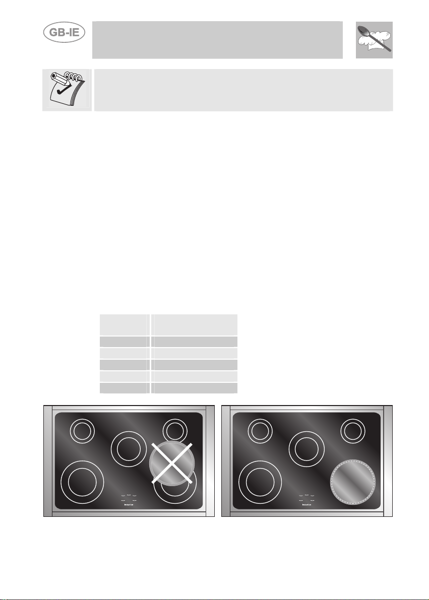
Metal items such as cutlery or lids must never be placed on the surface
of the hob since they may become hot.
4.1 Cooking zones
The appliance is equipped with 5 cooking
zones having different diameters and powers.
Their positions are clearly marked by rings,
while the heating power is only released in the
area shown on the ceramic hob. The 5
cooking zones are of HIGH-LIGHT type and
start to heat up a few seconds after they are
switched on. The heat level of each zone can
be regulated from the minimum to the
maximum setting using the knobs on the front
panel.
Underneath each cooking zone there is a coil called an inductor,
supplied with power by an electronic system, which generates a variable
magnetic field. When a pan is placed inside this magnetic field, the highfrequency currents concentrate directly on the bottom of the pan and
produce the heat needed to cook the foods.
The 5 lights between the cooking zones come on when the
temperature of one or more cooking zones exceeds 60° C..
The lights go out when the temperature drops to below
about 60° C.
4.1.1 Operating Powers
The table below lists the consumption levels of the cooking zones when
in operation.
Zone
Number:
1 210 mm
2 145 mm
3 180 mm
4 145 mm
5 210 mm
Zone Diameter Power absorption
Normal operation: 2300 W
With power function: 3200 W
Normal operation: 1400 W
With power function: 1800 W
Normal operation: 1850 W
With power function: 2500 W
Normal operation: 1400 W
With power function: 1800 W
Normal operation: 2300 W
With power function: 3200 W
47
Page 14
When the hob is used for the first time, it should be heated to its
maximum temperature for long enough to burn off any oily residues left
by the manufacturing process, which might contaminate foods with
unpleasant smells.
4.1.2 Types of pans
This type of appliance can only operate with pans of special kinds.
The bottom of the pan must be iron or steel/iron to generate the magnetic
field necessary for the heating process.
Vessels made from the following materials are not suitable:
− glass;
− porcelain;
− pottery;
− steel, aluminium or copper without magnetic bottom;
To check that a pan is suitable, simply place a magnet close to its bottom:
if the magnet is attracted, the pan is suitable for induction cooking. If no
magnet is to hand, put a little water in the pan, place it on a cooking zone
and switch it on. If the symbol appears on the display instead of the
power, the pan is not suitable.
The pans used for cooking must have certain minimum diameters to
ensure satisfactory operation.
The table below states the minimum pan diameters for each cooking
zone.
Instructions for the User
Zone
Number
1 140 mm
2 90 mm
3 110 mm
4 90 mm
5 140 mm
Pan minimum
diameter
Pans larger than the cooking zones
can also be used, but it is important
to ensure that the bottom of the pan
does not touch other cooking zones,
and that it is always centred over
the perimeter of the cooking zone.
48
Page 15

Instructions for the User
Use only vessels specially designed for induction cooking, with thick,
completely flat bottom; if these are not available, the pans used must
not have crowned (concave or convex) bottom.
YES NO NO
4.1.3 Pan present device
Each cooking zone is equipped with a "pan present" device, which
ensures that cooking cannot start unless a suitable pan is present on the
cooking zone and properly positioned.
If the user attempts to switch on the cooking zone with the pan not
positioned properly or with a pan which is not of suitable material, a few
seconds after the zone is switched on the
the user that an error has been made.
4.1.4 Residual heat
Each cooking zone is equipped with a device which warns of residual
heat. After any cooking zone is switched off, a flashing “
on the display. This warns that the cooking zone concerned is still very
hot. Cooking can be restarted while the
described in point "3".
4.1.5 Locking-out the hob
When not in use, the hob can be "locked out" to prevent children from
accidentally switching it on.
With the cooking zones off, turn the knobs of zones 2 and 4 to the left
simultaneously until 5 Ls appear on the power display and then release
the knobs.
To deactivate it, repeat the same procedure: the cooking zone displays
will all show 0, indicating that the cooking zone lock-out function has
been deactivated.
symbol will appear to warn
is flashing; proceed as
” may appear
49
Page 16

4.1.6 Electronic circuit board thermal protection
The appliance is equipped with a device which constantly measures the
temperature of the electronic circuit board.
If the temperature should exceed preset values, the device will trigger
specific functions to reduce the temperature and allow the ceramic hob to
keep operating correctly.
The following table lists the automatically triggered procedures and the
relative trigger temperature:
Instructions for the User
Operation
Trigger
temperature
Fan switches on at low speed 50 °C
Fan switches on at high speed 60 °C
Fan switches back to low speed 55 °C
Fan switches off 45 °C
Operating power is reduced from Power function to 9 76 °C
Operating power is reduced by one point for each
85 °C
cooking zone
All cooking zones switch off 90 °C
Cooking zones switch back on at reduced power 85 °C
All cooking zones return to normal operation 80 °C
The power displays on the hob flash to signal all operations of this kind.
4.1.7 Ceramic hob thermal protection
Each cooking zone is equipped with a device which constantly measures
its temperature.
If the temperature should exceed preset values, the device will trigger
specific functions to reduce the temperature and allow the ceramic hob to
keep operating correctly.
The following table lists the automatically triggered procedures and the
relative trigger temperature:
Operation
Trigger
temperature
Operating power is reduced from Power function to 9 250 °C
Operating power is reduced by one point 280 °C
Cooking zone switches off 300 °C
Power returns to set value 250 °C
The power displays on the hob flash to signal all operations of this kind.
50
Page 17

Instructions for the User
Take care not to spill sugar or sweet mixtures onto the
hob during cooking, or to place materials or
substances which might melt (plastic or aluminium foil)
on it; if this should occur, to avoid damage to the
surface, turn the heating off immediately and clean
with the scraper supplied while the cooking zone is still
warm. If the ceramic hob is not cleaned
immediately, residues may form which cannot be
removed once the hob has cooled.
Important!
Keep a close eye on children because they are unlikely to see the
residual heat warning lights. The cooking zones are still very hot for
some time after use, even if they are switched off. Make sure that
children never touch them.
4.2 Holding Function
The holding function keeps the temperature of the bottoms of pans at
about 65°C. This allows foods to be kept hot with optimal energy
consumption and to be heated gently. The holding function can be kept
in operation for up to 2 hours.
The holding function is between [0] and [1] and is indicated by the
relevant symbols on the cooking zones.
51
Page 18

Instructions for the User
5. USING THE OVEN
5.1 Precautions and General Advice
When the oven is used for the first time, it should be heated to the
maximum temperature (250°C) for long enough to burn off any oily
residues left by the manufacturing process, which might contaminate
foods with unpleasant smells.
At first use after a power blackout, press the middle knob
seconds to enable oven cooking operations. For setting instructions, see
point "3.2. Electronic Programmer”.
During cooking, do not cover the bottom of the oven with aluminium or
tin foil, and do not place pans or trays on it; this may damage the enamel
coating. If you wish to use greaseproof paper, position it so that it does
not interfere with the hot air circulation inside the oven.
To avoid unpleasant contact with any steam
inside the oven, open the door in two stages: hold
5 cm
it half-open (about 5 cm) for 4-5 seconds, then
open it completely. If you have to carry out any
procedures on foods, leave the door open for as
short a time as possible to prevent a drop in the
oven temperature which will impair the cooking
results.
for 1 - 2
52
5.2 Oven light
It comes on when the function selector is turned to any setting, or when
the door is opened with the oven off.
5.3 Storage compartment
The storage drawer is in the bottom of the
cooker, underneath the oven. To open it,
pull on the bottom of the door.
Never use it to store flammable materials
such as rags, paper, etc.; it is intended to
take the appliance's metal accessories only.
Never open the storage compartment when the oven is on and still hot.
The temperatures inside it may be very high.
Page 19

Instructions for the User
6. ACCESSORIES AVAILABLE
The oven is fitted with 4 runners for placing
trays and shelves at different heights.
Oven shelf: for cooking food on plates,
small cakes or roasts or foods requiring light
grilling.
Tray grid: for placing on top of a tray for
cooking foods which may drip.
Oven tray: useful for collecting fat from
foods placed on the grid above.
Baking tray: useful for cooking cakes, pizza
and confectionery.
Rotisserie rod: useful for cooking chicken,
sausages, kebabs and all foods which
require uniform cooking over their entire
surface.
Rotisserie supports: for fitting into the
holes in the oven tray before the rotisserie
rod is used.
53
Page 20

Instructions for the User
7. COOKING ADVICE
The oven should always be preheated in fan mode to 30/40°C above the
cooking temperature. This considerably shortens cooking times and
reduces electricity consumption, as well as giving better results.
The oven door must be closed during cooking operations.
7.1 Conventional cooking
FUNCTION SELECTOR
THERMOSTAT SET AT 50 - 250°C
This conventional cooking method, with heat from above and below, is
suitable for cooking food on just one shelf. The oven must be preheated
to the preset temperature. Do not place the food in the oven until the
thermostat light goes out. Very fatty meats can be placed inside the oven
when it is still cold. Place frozen meat in the oven directly, without
thawing. The only precaution required is to set temperatures about 20°C
lower and cooking times about 1/4 longer than for fresh meat.
Use deep containers to prevent splashes from
dirtying the sides of the oven.
54
Page 21
Instructions for the User
7.2 Hot air cooking
FUNCTION SELECTOR
THERMOSTAT SET AT 50 - 250°C
This system is suitable for cooking on several shelves, even with foods
of different kinds (fish, meat, etc.) without cross-contamination of
flavours or smells. The air circulation inside the oven ensures uniform
heat distribution. Preheating is not necessary.
Multiple cooking is possible provided that all foods require the same
temperature.
55
Page 22

Instructions for the User
7.3 Grilling
FUNCTION SELECTOR
THERMOSTAT AT MAXIMUM SETTING
Used for quick browning of foods. The tray should be placed on the top
runner. For short processes and small amounts, place the shelf on the third
runner from the bottom. For longer cooking times and grilling, place the shelf
on lower runners, depending on the size of the food.
The oven door must be closed while cooking is in progress.
Keep the door closed when grilling is in progress. Grilling with the
door open may permanently damage the oven and reduce
operating safety.
56
Page 23

Instructions for the User
7.4 Hot air grilling
FUNCTION SELECTOR
THERMOSTAT FROM 50° C TO 250°C
Allows uniform heat distribution with better penetration to the core of
foods. Foods are lightly browned on the outside but still soft on the
inside.
During cooking the oven door must be closed, and the maximum
heating time must not exceed 60 minutes.
Keep the door closed when grilling is in progress. Grilling with the
door open may permanently damage the oven and reduce
operating safety.
57
Page 24

Instructions for the User
7.5 Defrosting
FUNCTION SELECTOR
THERMOSTAT SET ON 0
The air movement provided by the fan alone thaws foods more quickly.
The air circulating inside the oven is at room temperature.
Defrosting at room temperature has the advantage that the food's flavour
and appearance are retained intact.
58
Page 25

Instructions for the User
7.6 Rotisserie cooking
FUNCTION SELECTOR
THERMOSTAT AT MAXIMUM SETTING
Prepare the rotisserie rod with the food, tightening the screws A of the
prongs. Fit the supports B into the holes in the tray F. Position the rotisserie
rod so that the pulley E is still in the recess of the support B on the right-hand
side, which acts as a guide. Insert the tray fully into the oven until the tip of
the rod is in line with the hole C. Now rock the supports B to insert the tip of
the rotisserie rod into the spit motor drive connection hole C in the side of the
oven. Pour a little water into the tray to prevent smoking.
The oven door must be closed while cooking is in progress.
It is normal for the thermostat light to switch on and off at regular
intervals during cooking; it indicates that the temperature inside the oven
is being kept constant.
WARNING: the supports B must be
fitted as shown on the right
59
Page 26

Instructions for the User
7.7 Recommended cooking tables
Cooking times, for meat in particular, vary depending on the food's
thickness and quality and personal preference.
RUNNER HEIGHT
PASTA
LASAGNE
PASTA BAKES
MEAT
ROAST VEAL
ROAST BEEF
ROAST PORK
CHICKEN
DUCK
GOOSE-TURKEY
RABBIT
LEG OF LAMB
ROAST FISH 1 - 2 170 - 200 DEPENDING ON
PIZZA 1 - 2 210 - 240 40 - 45
CONFECTIONERY
MERINGUES
PASTRY
SPONGE CAKE
BISCUITS
CROISSANTS
FRUIT CAKE
CONVENTIONAL COOKING
FROM BOTTOM
2 - 3
2 - 3
2
2
2
2
2
2
2
1
1 - 2
1 - 2
1 - 2
1 - 2
1 - 2
1 - 2
TEMPERATURE
(°C)
210 - 230
210 - 230
170 - 200
210 - 240
170 - 200
170 - 200
170 - 200
140 - 170
170 - 200
170 - 200
50 - 70
170 - 200
165
150
170 - 200
170 - 200
TIME
IN MINUTES (*)
30
40
30 - 40 PER KG.
30 - 40 PER KG.
30 - 40 PER KG.
45 - 60
45 - 60
45 - 60
50 - 60
15 PER KG.
SIZE
60 - 90
15 - 20
35 - 45
30 - 50
40 - 45
20 - 30
(*) = WITH OVEN PREHEATED
RUNNER POSITION
1ST SIDE 2ND SIDE
PORK CUTLET
PORK FILLET
FILLET STEAK
SLICED LIVER
VEAL ESCALOPE
HALF CHICKEN
SAUSAGE
MEATBALLS
FISH FILLET
TOASTED SANDWICHES
FROM THE BOTTOM
GRILLING
4
3
3
4
4
3
4
4
4
4
TIME IN MINUTES
7 - 9
9 - 11
9 - 11
2 - 3
7 - 9
9 - 14
7 - 9
7 - 9
5 - 6
2 - 4
5 - 7
5 - 9
9 - 11
2 - 3
5 - 7
9 - 11
5 - 6
5 - 6
3 - 4
2 - 3
60
Page 27

Instructions for the User
RUNNER HEIGHT
PASTA
LASAGNE
PASTA BAKES
CREOLE RICE
MEAT
ROAST VEAL
ROAST PORK
ROAST BEEF
FILLET STEAK
ROAST LAMB
RARE ROAST BEEF
ROAST CHICKEN
ROAST DUCK
ROAST TURKEY
ROAST RABBIT
ROAST HARE
ROAST PIGEON
FISH 2 - 3 150 - 170 DEPENDING ON
PIZZA 2 - 3 210 - 240 30 - 50
SWEETS (CONFECTIONERY)
SPONGE CAKE
FRUIT CAKE
LIGHT SPONGE CAKE
CROISSANTS
APPLE TART
BISCUIT PUDDING
BREAD
TOASTED SANDWICHES
HOT-AIR COOKING
FROM BOTTOM
2
2
2
2
2
2
2
2
2
2
2
2
2
2
2
2 - 3
2 - 3
2 - 3
2 - 3
1 - 2
2 - 3
2 - 3
1 - 2
TEMPERATURE
(°C)
190 - 210
190 - 210
190 - 220
150 - 170
150 - 160
160 - 170
160 - 180
130 - 150
170 - 180
170
160 - 170
150 - 160
150 - 160
160 - 170
140 - 170
150 - 170
170 - 190
190 - 220
160 - 170
150
160 - 170
190 - 210
220 - 240
TIME
IN MINUTES
20 - 25
25 - 30
20 - 25
65 - 90
70 - 100
65 - 90
35 - 45
100 - 130
40 - 45
70 - 90
100 - 160
160 - 240
80 - 100
30 - 50
15 - 25
SIZE
35 - 45
40 - 50
25 - 35
40 - 60
25 - 35
30 - 40
40
7
61
Page 28

Instructions for the User
8. CLEANING AND MAINTENANCE
8.1 Cleaning the ceramic hob
Before carrying out any operations, disconnect the appliance from
the electricity supply.
The ceramic hob must be cleaned regularly, preferably after each use,
when the residual heat warning lights have gone out.
Any marks left by the use of pans with aluminium
bottoms can be wiped off with a cloth dipped in
vinegar.
If burnt residues are left after cooking, remove them
with the scraper provided, rinse with water and dry
thoroughly with a clean cloth. Regular use of the
scraper considerably reduces the use of chemicals for
daily cleaning of the hob.
In any case, abrasive or corrosive cleaners (e.g. powder products, ovencleaner sprays, stain removers and metal scouring pads) must never be
used.
8.2 Cleaning stainless steel
8.2.1 Routine daily cleaning
When cleaning and caring for stainless steel surfaces, always use only
specific products which do not contain abrasives or chlorine-based acids.
Instructions for use: pour the product onto a damp cloth and wipe over
the surface, then rinse thoroughly and dry with a soft cloth or chamois
leather.
8.2.2 Food stains or spills
Never use metal scouring pads or sharp scrapers; they will
damage surfaces.
Use ordinary non-abrasive products for steel, with the aid of
wooden or plastic utensils if necessary.
Rinse thoroughly and dry with a soft cloth or chamois leather.
Do not allow spills of foods with high sugar content (e.g. jam) to
dry inside the oven. If they dry for too long, they might damage
the enamel coating of the inside of the oven.
62
Page 29
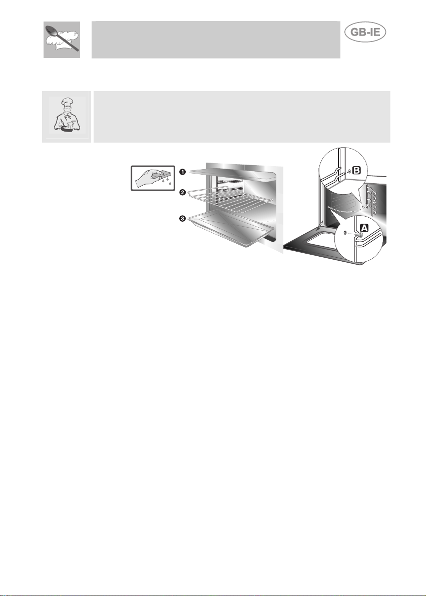
8.3 Cleaning the oven (without self-cleaning liners)
To keep the oven in good condition, it must be cleaned regularly, after
allowing it to cool down. Remove all removable parts.
Remove the side runners by unscrewing the ring-nut A and extract them
through the hole in the rear B.
• Clean the oven shelves and side runners with hot water and nonabrasive detergents, rinse and dry.
8.3.1 Self-cleaning liners
The oven is fitted with enamelled liners that are continuously self-cleaning.
These liners simplify cleaning of the oven and ensure it continues to
perform well over time.
8.3.2 Using the self-cleaning liners
To keep the inside of the oven clean and free from food residues and
unpleasant smells, it should periodically be operated empty at a
temperature of at least 200° C for a time varying between 30 and 60
minutes. This allows the self-cleaning liners to oxidise any deposits
present, which can then be wiped away with a damp sponge once the
oven has cooled.
8.3.3 Maintenance of self-cleaning liners
The liners should not be cleaned using abrasive creams and ordinary
cleaners. Simply wipe with a damp sponge to avoid damaging the special
enamel coating.
Instructions for the User
63
Page 30

8.3.4 Removing the self-cleaning liners
Remove all accessories from the inside of the oven and proceed as
follows:
1. Remove the side runners (fig.1);
2. Extract the side liners "F" and "G" (fig. 2);
3. Extract the back liner "A" after undoing the threaded ring-nut "C" (fig.
2);
4. Replace the liners in their original positions.
Instructions for the User
1)
2)
8.4 Door glazing
The glass in the door should always be kept thoroughly clean. Use
absorbent kitchen roll; remove stubborn dirt with a damp sponge and
ordinary detergent.
64
Page 31

Instructions for the User
9. EXTRAORDINARY MAINTENANCE
Occasionally, the oven will require minor servicing procedures or the
replacement of parts subject to wear and tear, such as gaskets, light
bulbs, etc. The specific operations for each procedure of this kind are
provided below.
Before carrying out any operations, disconnect the appliance from
the electricity supply.
9.1 Changing the light bulb
Remove the protective cover A by unscrewing it anticlockwise and
replace the bulb B with another of the same type. Replace the protective
cover A.
Use only light bulbs approved for ovens (T 300°C).
65
Page 32

9.2 Removing the door
Open the door completely and insert the pins (supplied) into the holes from
the inside. Close the door to an angle of about 45° and lift it off. To
reassemble, fit the hinges into their grooves, then lower the door into place
and extract the screwdrivers.
Instructions for the User
9.3 Oven door gasket
To allow thorough cleaning of the oven, the door
gasket can be removed. Before removing the gasket,
remove the oven door as described above. Once the
door has been removed, lift the tangs at the corners
of the gasket as shown.
66
 Loading...