

Page 1
Instructions for the installer
INSTRUCTIONS FOR TRANSFORMATION
THIS MANUAL IS AN INTEGRAL PART OF THE APPLIANCE. IT MUST BE KEPT
IN ITS ENTIRETY AND IN AN ACCESSIBLE PLACE FOR THE WHOLE
WORKING LIFE OF THE PRODUCT. INSTALLATION MUST BE CARRIED OUT
BY QUALIFIED PERSONNEL IN ACCORDANCE WITH THE REGULATIONS IN
FORCE. THE MANUFACTURER DECLINES ALL RESPONSIBILITY FOR
IMPROPER USE.
This kit sold separately is designed specifically for transformation of
barbecue fuelling from GPL gas to METHANE gas.
The kit includes all the components and the instructions necessary in
order to make the modification.
The appliance is factory set to run on GPL gas; to transform it (using the
following kit) you must change the nozzles on all the burners, regulate the
primary air only of the barbecue compartment burners and also regulate
the minimum flame on the gas taps.
At the end of these operations, replace the label “regulated for gas” on the
back of the barbecue with the label provided in the kit.
The installation must be carried out by a specialised technician.
WARNING: Keep the product's standard installation nozzles and the
“regulated for gas” label, since reconversion from METHANE gas to GPL
gas could be necessary in the future.
In the case of reconversion to GPL gas, the conversion procedure is
identical to that described below for METHANE gas.
KIT CONTENTS
The contents of the methane gas transformation kit are listed below:
• NOZZLES FOR METHANE GAS.
• SEALING GASKET.
• LABEL “REGULATED FOR GAS”
TRANSFORMATION).
10
(TO BE APPLIED AFTER THE
Page 2
Instructions for the installer
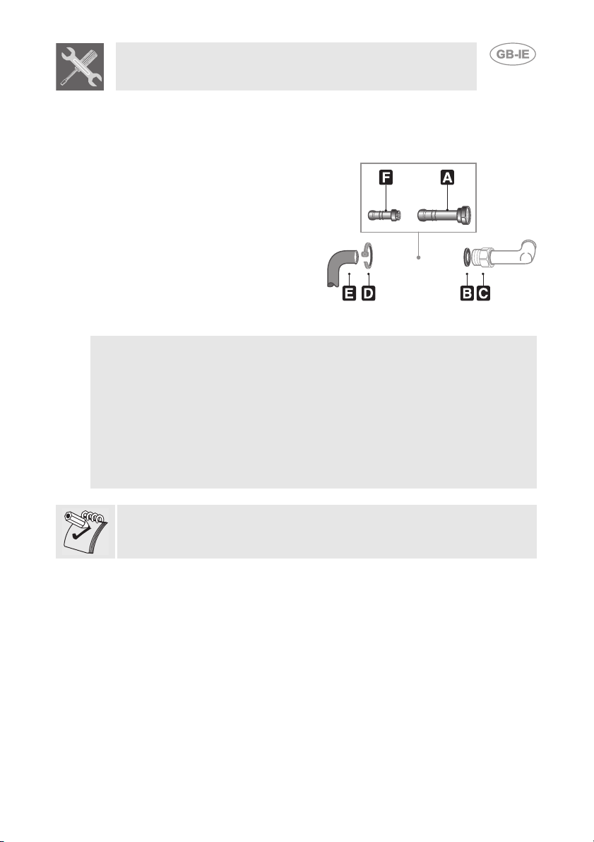
GAS MAINS CONNECTION
The product must be connected to the
methane gas mains by means of a
standards-compliant rubber or flexible
steel hose.
Screw the connector (A) inserting the
sealing gasket (B) at the barbecue inlet
connector (C); see the drawing at the
side. Depending on the diameter of the
hose, you may or may not need to attach
smaller connector (F) to the connector
(A) attached previously.
Push the hose (E) onto the connector (A)
or (F) and secure it to the connector by
means of a clamp (D).
Verify that the following conditions are met:
• the hose is fixed to the hose connection with safety clamps.
• it is possible to inspect the entire length of the hose (max 1.5 m).
• no part of the hose is in contact with the hot walls (max. 50°C).
• the hose is not under traction or tension and has no tight curves or twists.
• the hose is not in contact with sharp objects or sharp corners.
• if the hose is not perfectly airtight and leaks gas, do not try to repair it;
replace it with a new tube.
• verify that the hose is not beyond its life cycle.
If the product was installed on a trolley (optional) lock the wheels using the
appropriate stops. Any traction or tension forces exerted on the hose
could jeopardise the safety of the product.
11
Page 3
Instructions for the installer
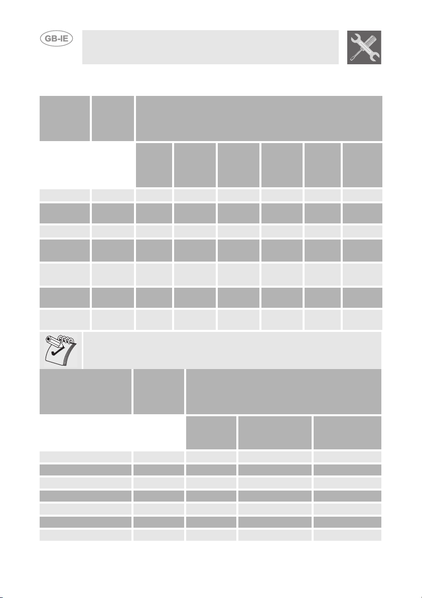
BURNER, NOZZLE AND GAS CONSUMPTION CHARACTERISTICS
BQ61T - BQ6130T - BQ91T
Rated
Burner
Left 4.5 closed 100
Centre
(BQ91T)
Right 4.5 closed 100
Radiating
grill
Radiating
grill (BQ91T)
Rapid
(BQ6130T)
Auxiliary
(BQ6130T)
heating
capacity
(kW)
no.
turns
by-pass
4.5 closed 100
3.8 1 + 1/4 95
4.5 1 + 1/4 105
3.0 closed 85
1.05 closed 50
In the column no. turns by-pass, closed means screwed in fully.
LPG – G30/G31 30/37 mbar
Nozzle
diameter
1/100
mm
By-pass
1/100
mm
85
85
85
Reg.
Reg.
45
30
Reduced
flowrate
(W)
2200
2200
2200
2500
2700
800
400
Flow-
rate
g/h G30
327 321
327 321
327 321
276 271
327 321
218 214
76 75
Flow-
rate
g/h G31
Rated
Burner
Left 4.5 360° + 90° 150 2200
Centre (BQ91T) 4.5 360° + 90° 150 2200
Right 4.5 360° + 90° 150 2200
Radiating grill 3.8 360° + 360° 145 2500
Radiating grill (BQ91T) 4.5 720° + 180° 155 2700
Rapid (BQ6130 - S) 3.0 180° 108 800
Auxiliary (BQ6130 - S) 1.05 180° 72 400
12
heating
capacity
(kW)
Methane gas – G20 20 mbar
no. turns
by-pass
Nozzle diameter
1/100 mm
Reduced
flowrate
(W)
Page 4

Instructions for the installer
BQ61 - BQ6130 - BQ91 - BQ61S - BQ6130S - BQ91S
Rated
Burner
Left 3.0 closed 80
Centre left
(BQ91S - BQ91)
Centre 3.0 closed 80
Centre right
(BQ91S - BQ91)
Right 3.0 closed 80
Rapid
(BQ6130 - S)
Auxiliary
(BQ6130 - S)
heating
capacity
(kW)
no.
turns
by-pass
3.0 closed 80
3.0 closed 80
3.0 closed 85
1.05 closed 50
In the column no. turns by-pass, closed means screwed in fully.
Nozzle
diameter
1/100
mm
LPG – G30/G31 30/37 mbar
By-pass
1/100
mm
75
75
75
75
75
45
30
Reduced
flowrate
(W)
1800
1800
1800
1800
1800
800
400
g/h G30
Flow-
rate
Flowrate
g/h G31
218 214
218 214
218 214
218 214
218 214
218 214
76 75
Rated
Burner
Left 3.0 315° 123 1800
Centre left (BQ91S - BQ91) 3.0 315° 123 1800
Centre 3.0 315° 123 1800
Centre right (BQ91S - BQ91) 3.0 315° 123 1800
Right 3.0 315° 123 1800
Rapid (BQ6130 - S) 3.0 180° 115 800
Auxiliary (BQ6130 - S) 1.05 180° 72 400
heating
capacity
(kW)
Methane gas – G20 20 mbar
rotation
by-pass
Nozzle diameter
1/100 mm
Reduced
flowrate
(W)
13
Page 5

Instructions for the installer
CHANGING THE NOZZLES
CHANGING THE BURNER COMPARTMENT
NOZZLES
1 Remove the grills and refractory plates (where
present) located inside the barbecue compartment.
2 Unscrew the screw(s) (for each burner) located on
the rear crosspiece.
3 Remove the burners from the barbecue
compartment.
4 Using a 7mm socket wrench, unscrew the nozzles
positioned on the taps (Change the nozzles
according to the table provided above).
5 Regulate the air (see primary air adjustment). 6 Replace the burners correctly and screw the
holding screws.
CHANGING THE RADIATING GRILL NOZZLES
(ONLY ON MODELS BQ61T - BQ6130T - BQ91T)
1 Remove the rear part of the barbecue by
unscrewing the support screws.
2 Using a 7mm wrench unscrew the nozzle (1). 3 Change the nozzles according to the table
provided above. To facilitate the nozzle insertion
operations the nut can be unscrewed (2).
4 Screw back the nut (2) taking great care. 5 Replace the rear part, screwing it into place with
the holding screws.
REPLACING RAPID - AUXILIARY BURNER
NOZZLES
(
ONLY ON MODELS BQ6130T - BQ6130S - BQ6130)
1 2
1 Remove the grids, the caps and the flame-
spreader crowns;
2 Using a 7mm wrench unscrew the nozzle of the
burner.
3 Change the nozzles according to the table
provided above.
4 Replace the burners, the caps and the flame-
spreader crowns correctly in their appropriate
positions.
14
Page 6

Instructions for the installer
PRIMARY AIR ADJUSTMENT
Carry out the following operations for every burner
present in the barbecue compartment:
PRIMARY AIR ADJUSTMENT WITH “SINGLE
PARALLEL FLAME” BURNERS
1 Loosen the adjustment screw A of the air
regulation sleeve.
2 Turn the registration sleeve B to the position that
corresponds to the type of gas to be used
according to the table below.
3 Tighten the adjustment screw making sure that the
distance X is correct (See table below).
PRIMARY AIR ADJUSTMENT WITH “DUAL
PARALLEL FLAME” BURNERS
1 Loosen the adjustment screw A of the air
regulation sleeve.
2 Extract or insert the registration sleeve B to the
position that corresponds to the type of gas to be
used according to the table below.
3 Tighten the adjustment screw making sure that the
distance X is correct (See table below).
X
A
B
METHANE (N)
Single parallel
flame burners
X= 1.5 mm 4 mm 4 mm 8 mm
G30/G31 (GPL)
Single parallel
flame burners
METHANE (N)
Dual parallel
flame burners
G30/G31 (GPL)
Dual parallel
flame burners
15
Page 7

Instructions for the installer
BURNER MINIMUM ADJUSTMENT
CONVERSION FROM GPL GAS TO METHANE
GAS
Carry out the following operations on all the gas taps.
1 Extract the knob. 2 Make sure that the by-pass inside is fully screwed
in. Use a screw driver inside the tap rod or at the
side (See the drawing at the side).
3 Turn the by-pass according to the table BURNER,
NOZZLE AND GAS CONSUMPTION
CHARACTERISTICS (see page 11).
4 When the adjustments are completed, insert the
knob and light the relative burner bringing it to the
minimum position . The flame at minimum
should be regular.
5 Check the stability of the flame by rapidly turning
the knob from the maximum to the minimum
position. The flame should not go out.
6 If the minimum flame is not regular, remove the
knob and move the by-pass with small clockwise
or counter-clockwise turns and repeating the flame
stability check. If the flame is regular, the minimum
adjustment operation has been successful.
CONVERSION FROM METHANE GAS TO GPL
GAS
Carry out the following operations on all the gas taps.
1 Extract the knob. 2 Turn the by-pass inside, screwing it in fully. Use a
screw driver inside the tap rod or at the side (See
the drawing at the side).
3 In the case of the grill tap, after having screwed
the by-pass fully in, unscrew it 360° + 90 °.
16
 Loading...