

Page 1
Instructions for the Installer
CONVERSION INSTRUCTIONS
THIS MANUAL IS AN INTEGRAL PART OF THE APPLIANCE. TAKE GOOD CARE
OF IT AND KEEP IT TO HAND THROUGHOUT THE APPLIANCE'S LIFE CYCLE.
INSTALLATION MUST BE CARRIED OUT BY QUALIFIED STAFF IN
COMPLIANCE WITH THE RELEVANT REGULATIONS. THE MANUFACTURER
DECLINES ALL LIABILITY FOR IMPROPER USES OTHER THAN THOSE
STATED ABOVE.
This kit, for separate sale, has been specially designed to convert the
barbecue from LPG to NATURAL GAS.
It contains all the components and instructions necessary for the
conversion procedure.
The appliance is set in the factory to operate on LPG. The conversion
procedure (requiring the kit described below) involves replacement of all
the burner nozzles, adjustment of the primary air flow of the barbecue
section burners only, and adjustment of the minimum flame setting on the
gas taps.
On completion of these operations, replace the “regulated for gas” label on
the rear of the barbecue with the one supplied in the kit.
The installation work must be carried out by a skilled technician.
WARNING: Keep all the nozzles factory-fitted on the appliance, the union
supplied and the “regulated for gas” label. It might be necessary to convert
the appliance back from NATURAL GAS to LPG in the future.
When converting back to LPG the conversion procedure is exactly the
same as that described below for NATURAL GAS.
CONTENTS OF THE KIT
The contents of the natural gas conversion kit are listed below:
• NATURAL GAS NOZZLES.
• 5/8" TO 1/2" GAS MALE UNION.
• SEAL.
• "REGULATED FOR" LABEL
(TO BE APPLIED AFTER CONVERSION).
9
Page 2
Instructions for the Installer
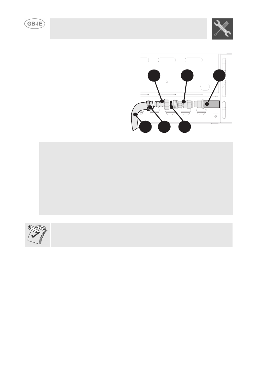
CONNECTION TO THE MAINS GAS SUPPLY
Connect the appliance to the mains
natural gas supply using a rubber or
steel hose in accordance with the
relevant regulations.
Screw the 5/8”-1/2” union (B)
supplied onto the barbecue's gas
inlet (C).
Screw the union (A) onto the union
(B) fitting the seal (D) between
them, as shown. Fit the hose (F)
onto the union (A) and secure it with
a band clamp (E).
Check that all the conditions listed below are met:
• the hose must be fixed to the hose connector with a safety band clamp;
• the hose must be accessible for inspection along its entire length (max. 1.5 m).
• the hose must not touch hot surfaces at any point (max. 50°C).
• there must not be any traction forces or stresses acting on the hose or any
tight bends or kinks in it.
• the hose must not touch sharp components or edges.
• if the hose is not perfectly gastight and causes gas leaks, do not attempt
to repair it ; replace it with a new hose.
• check that the hose's expiration date has not been passed.
A
EF
B
D
C
10
If the appliance has been mounted on the optional trolley, lock the wheels
using the clamps provided. Any pulling or tension on the hose might
reduce the appliance's safety level.
Page 3

Instructions for the Installer
BURNER, NOZZLE AND GAS CONSUMPTION DATA TABLES
Rated
Burner
Left 4.5 closed 100
Central
(BQ90T)
Right 4.5 closed 100
Radiant grill 3.8 1 + 1/4 95
Radiant grill
(BQ90T)
Ultrarapid
(BQ6030T)
heat
capacity
(kW)
n. turns
by-pass
4.5 closed 100
4.5 1 + 1/4 105
3.5 closed 94
In the by-pass n. of turns column, closed means fully screwed down.
Bottled gas – G30/G31 30/37 mbar
Nozzle
diameter
1/100
mm
By-pass
1/100
mm
85
85
85
Adj.
Adj.
65
Reduced
heat
capacity
(W)
2200
2200
2200
2500
2700
1500
Capacity
g/h G30
327 321
327 321
327 321
276 271
327 321
254 250
Capacity
g/h G31
Rated heat
Burner
Left 4.5 1 + 1/4 150 2200
Central (BQ90T) 4.5 1 + 1/4 150 2200
Right 4.5 1 + 1/4 150 2200
Radiant grill 3.8 2 145 2500
Radiant grill (BQ90T) 4.5 2 + 1/2 155 2700
Ultrarapid (BQ6030T) 3.5 1 133 1500
capacity
(kW)
n. turns
by-pass
Natural gas - G20 20 mbar
Nozzle diameter
1/100 mm
Reduced heat
capacity
(W)
11
Page 4

Instructions for the Installer
CHANGING THE NOZZLES
REPLACING THE BURNER SECTION NOZZLES
1 Remove the grids and refractory plates inside the
barbecue section.
2 Undo the screws (for each burner) on the rear
cross-member.
3 Remove the burners from the barbecue section. 4 Using a 7 mm socket wrench, undo the nozzles on
the taps (replace the nozzles as specified in the
table above).
5 Adjust the primary air flows (see adjusting primary
air flows section).
6 Put the burners back into place correctly and
tighten the fixing screws.
REPLACING THE RADIANT GRILL NOZZLES (ON
TOP VERSIONS ONLY)
1 Remove the rear of the barbecue by undoing the
supporting screws.
2 Using a 7 mm spanner, unscrew the nozzle (1). 3 Replace the nozzles as specified in the table
above. To make it easier to fit the nozzle, the nut
(2) can be unscrewed.
4 Retighten the nut (2) with great care. 5 Fit the rear part back into place and screw on with
the fixing screws.
REPLACING THE ULTRARAPID BURNER NOZZLE
(BQ6030 MODELS ONLY)
1 Remove the grid, the burner cap and the flame
diffuser ring.
2 Using a 7 mm socket wrench, unscrew the burner
nozzle.
3 Replace the nozzle as specified in the table above. 4 Put the burner, the burner cap and the flame
diffuser ring back into place correctly.
5 Fit the rear part back into place and screw on with
the fixing screws.
1 2
12
Page 5

Instructions for the Installer
ADJUSTING THE PRIMARY AIR FLOWS
The operations below must be carried out for every
burner in the barbecue section:
ADJUSTING THE PRIMARY AIR FLOW FOR "U"SHAPED BURNERS
1 Undo the adjuster screw A of the air regulator
sleeve.
2 Turn the regulator sleeve B into the position for the
type of gas to be used, consulting the table below.
3 Tighten the regulator screw, making sure that the
distance X is correct (see table below).
ADJUSTING THE PRIMARY AIR FLOW FOR
"PARALLEL FLAME" BURNERS
1 Undo the adjuster screw A of the air regulator
sleeve.
2 Pull the regulator sleeve B out or push it in to
achieve the position for the type of gas to be used,
consulting the table below.
3 Tighten the regulator screw, making sure that the
distance X is correct (see table below).
X
X
A
B
A
B
NATURAL GAS
(N) U-shaped
burners
X = 4 mm 8 mm 2 mm 8 mm
G30/G31 (LPG)
U-shaped
burners
NATURAL GAS (N)
Parallel flame
burners
G30/G31 (LPG)
Parallel flame
burners
13
Page 6

Instructions for the Installer
ADJUSTING THE BURNER MINIMUM SETTING
CONVERTING FROM LPG TO NATURAL GAS
Perform the operations described below on all the gas
taps.
1 Pull off the knob. 2 Make sure that the by-pass inside is screwed fully
down. Use a screwdriver inside or on the side of
the rod (see right).
3 Turn the bypass as stated in the BURNER
CHARACTERISTICS, NOZZLES AND GAS
CONSUMPTION table (see page 10).
4 When adjustments are complete, fit the knob, light
the relative burner and turn it to the minimum
setting . The flame should be even at the
minimum setting.
5 Check that the flame remains stable when the
knob is turned quickly from the maximum to the
minimum setting. The flame must not go out.
6 If the minimum flame is not even, remove the knob
and make small clockwise or anti-clockwise
adjustments to the bypass then check stability
again. Otherwise the minimum flame has been
adjusted successfully.
CONVERTING FROM NATURAL GAS TO LPG.
Perform the operations described below on all the gas
taps.
1 Pull off the knob. 2 Turn the by-pass inside, screwing it fully down.
Use a screwdriver inside or on the side of the rod
(see right).
3 For the grill tap, after screwing the bypass fully
down back it off by 1+1/4 turn.
14
 Loading...