

Page 1
Important Safety Instruction
IMPORTANT SAFETY INSTRUCTIONS
READ AND SAVE THESE INSTRUCTIONS – Your safety and the safety of others are very important.
We have provided many important safety messages throughout this manual and on the appliance.
Read all instructions before using the appliance and always obey all safety messages.
RECOGNIZE SAFETY INFORMATION
This is a safety alert symbol. This symbol alerts you to potential hazards that can kill or hurt you and
others.
UNDERSTAND SIGNAL WORDS
A signal word – DANGER, WARNING, or CAUTION – is used with the safety-alert symbol. DANGER
identifies the most serious hazards. It means you can be killed or seriously injured if you do not
immediately
follow the instructions. CAUTION indicates a potentially hazardous situation which, if not avoided, may
result in minor or moderate injury.
All safety messages will inform you of potential hazards, on how to reduce the risk of injury and what
can occur if the instructions are not followed.
IMPORTANT: Observe all governing codes and ordinances.
follow the instructions. WARNING means you can be killed or seriously injured if you do not
WARNING: For your safety, the information in this manual must be followed to minimize the risk
of fire or explosion, or to prevent property damage, personal injury or death.
- This conversion kit must be installed by a qualified service agency in accordance with the
manufacturer's instructions and all applicable codes and requirements of the authority
having jurisdiction.
- The qualified service agency is responsible for the proper installation of this kit.
- The installation shall not be considered to be correct and completed until the operation of the
converted appliance is checked as specified in the manufacturer's instructions supplied with
this kit.
FIRE HAZARD
WARNING
Securely tighten all gas connections. If connected to LP, have a qualified
person ensure that the gas pressure does not exceed 14" water column.
Examples of a qualified person include licensed heating personnel,
authorized gas company personnel, and authorized service personnel.
FAILURE TO DO SO CAN RESULT IN DEATH, EXPLOSION, OR FIRE.
3
Page 2
1)
2)
Conversion Kit
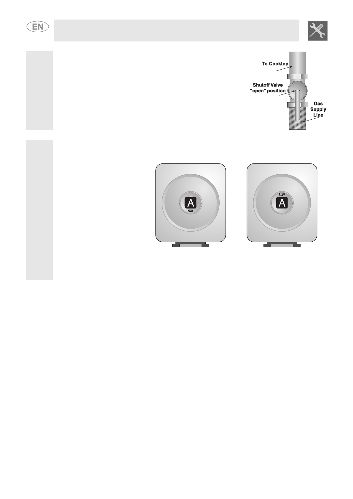
Check that the main gas supply line to the range is shut off and that the
power supply cord is disconnected.
Remove access cap “A” by using a screwdriver or a quarter, turning the access cap counter-clockwise.
The gas pressure regulator has two settings which are indicated on two sides of the cap. Turn the cap
and reinstall it in the regulator with "LP" visible from the outside of the regulator.
The regulator must be checked at
a minimum water column of 1 inch
(2.5 cm) above the set pressure.
The inlet pressure to the regulator
should be as follows for operation
and checking the regulator
setting: - NATURAL GAS: Set
pressure at 4” W.C. Supply
pressure of 3
maximum; - LP GAS: Set
pressure at 11” W.C. Supply
pressure of 8” - 13” W.C.
maximum.
The range must be isolated from the gas supply piping system by closing the respective manual shut-off
valve during any pressure testing of the gas supply piping system at test pressures equal to or greater
than 1/2 psig (3.5 kPa).
1
/2” - 10 1/2” W.C.
4
Page 3

3)
Conversion Kit
This operation requires no primary air regulation.
1 Extract the grids and remove all the caps and flame-spreader crowns;
2 Unscrew the burner nozzles with a 7 mm socket wrench;
3 Replace the nozzles according to the type of gas to be used and the description in paragraph 3.2
“Burner and nozzle characteristics table”.
Put the burners back in their correct position.
5
Page 4

4)
Conversion Kit
To adjust the cooktop for LP gas or to return to
Natural Gas use, refer to the tables below.
Natural gas
Qt Injector Qr
BTU Ø mm BTU
Front Right 5200 1.10 1500
Front Left 3400 0.90 1200
Central
Rear Right 10000 1.52 2600
Rear Left 10000 1.52 2600
Front Right 5200
Front Left 3400
Central
Rear Right 10000
Front Left 10000
Inner 3000 0.85 1200
Outer 12000 1.17-1.17 4500
LP
Qt Injector Qr By-pass
BTU Ø mm BTU mm
Inner 3000
Outer 12000
0.65
(drw.0222)
0.54
(drw.0222)
0.50
(drw.0222)
0.70-0.70
(drw.0222)
0.90
(drw.0222)
0.90
(drw.0222)
1500 0.39
1200 0.33
1000 0.33
4000 0.65
2400 0.45
2400 0.45
NOTE: Save the nozzles removed from the appliance for future use.
FIRE HAZARD
WARNING
6
- Use a soapy solution to check for proper tightness.
- Never test for gas leaks with a match or other flames.
- Failure to follow this instruction can result in death or fire
Page 5

5)
6)
Conversion Kit
Minimum adjustment for Natural Gas
Light the burner and take it to the minimum.
Remove the gas tap knob and turn the adjustment screw inside or at the side of the tap
shaft (depending on the model) until there is a regular minimum flame.
Replace the knob and check burner flame stability: (rapidly turning the knob from
maximum to minimum position, the flame should not go out).
Repeat the operation on all the gas taps.
Minimum adjustment for LP
For regulating the minimum with LP, the screw at the side of the tap rod must be turned clockwise all the
way.
The bypass diameters for each individual burner are shown in point 4.
Once the regulation has been completed, replace the seal on the by-passes using paint or similar
materials.
7)
8)
9)
Completely fill out conversion label (part no. 91849A078) and attach the label in the storage
compartment beside the rating tag. Do not cover the rating tag with the conversion label.
At higher altitudes, no further adjustments are necessary. Derating the burners is also unnecessary.
Save the nozzles removed from the unit along with these instructions for possible future use.
NATURAL GAS:
To convert back to Natural Gas: Follow steps 3 through 5 and replace the nozzles in the order in which
they were removed.
7
 Loading...