

Document Revision: 7.E
Web Configurator
Template Revision: 71
T17022
ProtoNode FPC-N34 and ProtoNode FPC-N35
Start-up Guide
For Interfacing Weil-McLain Products:
SlimFit 1000-2000 Series 1 (SOLA), Evergreen, SlimFit 550-750 Series 2 & 3,
SlimFit 1000-2000 Series 2 and SVF Models
To Building Automation Systems:
BACnet MS/TP, BACnet/IP, Modbus TCP/IP, Metasys N2, LonWorks and
SMC Cloud
APPLICABILITY & EFFECTIVITY
Explains ProtoNode hardware and how to install it.
The instructions are effective for the above as of May 2019.

Weil-McLain ProtoNode Start-up Guide
Page 2 of 61
Technical Support
Thank you for purchasing the ProtoNode for Weil-McLain.
Please call Weil-McLain for technical support of the ProtoNode product.
Sierra Monitor Corporation does not provide direct support. If Weil-McLain needs to escalate the concern,
they will contact Sierra Monitor Corporation for assistance.
Support Contact Information:
Weil-McLain
500 Blaine Street
Michigan City IN
46360
Customer Service:
1.800.654.2109, Option 2
Email: wmtechnicalservices@weil-mclain.com
Website: www.Weil-McLain.com

Weil-McLain ProtoNode Start-up Guide
Page 3 of 61
Quick Start Guide
1. Record the information about the unit. (Section 3.1)
2. Configure the COM settings and Node-ID for any device to connect to the ProtoNode. (Section 3.3)
3. FPC-N34: Select the protocol configuration on the S Bank DIP switches. (Section 3.4)
4. BACnet MS/TP (FPC-N34): Set the MAC Address on the A Bank DIP switches. (Section 3.5.1)
5. BACnet MS/TP (FPC-N34): Set the baud rate of the BACnet MS/TP field protocol on the B Bank DIP
switches. (Section 3.5.2)
6. Connect the ProtoNode 6 pin RS-485 connector to the RS-485 network that is connected to each of
the devices. (Section 4.2)
7. Connect the ProtoNode FPC-N34 3 pin RS-485 port to the field protocol cabling, (Section 4.3)
or connect the ProtoNode FPC-N35 2 pin LonWorks port to the field protocol cabling. (Section 4.4)
8. Connect power to the ProtoNode 6 pin port. (Section 4.5)
9. Use a web browser to access the ProtoNode Web Configurator page to select the profiles of the devices
attached to the ProtoNode and enter any necessary device information. Once the devices are selected,
the ProtoNode automatically builds and loads the appropriate configuration. (Section 5)
10. Ethernet Network (FPC-N34): Use a web browser to access the ProtoNode Web Configurator page to
change the IP Address. No changes to the configuration are necessary. (Section 5.4)
11. LonWorks (FPC-N35): The ProtoNode must be commissioned on the LonWorks Network. This needs
to be done by the LonWorks administrator using a LonWorks commissioning tool. (Section 8)

Weil-McLain ProtoNode Start-up Guide
Page 4 of 61
TABLE OF CONTENTS
1 Certifications ........................................................................................................................................ 7
1.1 BTL Mark – BACnet® Testing Laboratory ....................................................................................... 7
1.2 LonMark Certification ...................................................................................................................... 7
2 Introduction .......................................................................................................................................... 8
2.1 ProtoNode Gateway ....................................................................................................................... 8
3 Setup for ProtoNode .......................................................................................................................... 10
3.1 Record Identification Data ............................................................................................................ 10
3.2 Point Count Capacity and Registers per Device .......................................................................... 10
3.3 Configuring Device Communications ........................................................................................... 11
3.3.1 Input COM Settings on Any Serial Device Connected to the ProtoNode ............................... 11
3.3.2 Set Node-ID for Any Device Attached to the ProtoNode ........................................................ 11
3.4 Selecting the Desired Protocol Configuration ............................................................................... 12
3.5 BMS Network Settings: MAC Address, Device Instance and Baud Rate .................................... 13
3.5.1 BACnet MS/TP (FPC-N34): Setting the MAC Address for BMS Network .............................. 13
3.5.2 BACnet (FPC-N34): Calculating the Default Device Instance ................................................ 14
3.5.3 BACnet MS/TP (FPC-N34): Setting the Baud Rate for BMS Network .................................... 14
3.5.3.1 Baud Rate DIP Switch Selection ..................................................................................... 14
4 Interfacing ProtoNode to Devices .................................................................................................... 15
4.1 ProtoNode FPC-N34 and FPC-N35 Showing Connection Ports .................................................. 15
4.2 Serial Device Connections to the ProtoNode ............................................................................... 16
4.2.1 Biasing the RS-485 Device Network ....................................................................................... 17
4.2.2 End of Line Termination Switch for the RS-485 Device Network ........................................... 18
4.3 Serial Network (FPC-N34): Wiring Field Port to RS-485 Network ............................................... 19
4.4 LonWorks (FPC-N35): Wiring LonWorks Devices to the LonWorks Terminal ............................. 20
4.5 Power-Up ProtoNode.................................................................................................................... 21
5 Use the ProtoNode Web Configurator to Setup the Gateway ....................................................... 22
5.1 Connect the PC to the ProtoNode via the Ethernet Port .............................................................. 22
5.1.1 Changing the Subnet of the Connected PC ............................................................................ 22
5.1.2 Changing the IP Address of the ProtoNode with FieldServer Toolbox ................................... 23
5.2 Connecting to the ProtoNode Web Configurator .......................................................................... 24
5.3 Selecting Profiles for Devices Connected to ProtoNode .............................................................. 24
5.3.1 Verify Device Communications ............................................................................................... 25
5.4 Ethernet Network: Setting IP Address for the Field Network ....................................................... 26
5.5 Change ProtoNode COM Settings........................................................................................ 28
6 BACnet: Setting Node_Offset to Assign Specific Device Instances ........................................... 29
7 How to Start the Installation Over: Clearing Profiles ..................................................................... 30
8 LonWorks (FPC-N35): Commissioning ProtoNode on a LonWorks Network.............................. 31
8.1 Commissioning ProtoNode FPC-N35 on a LonWorks Network ................................................... 31
8.1.1 Instructions to Upload XIF File from ProtoNode FPC-N35 Using Browser ............................. 31
Appendix A. Troubleshooting .................................................................................................................. 33
Lost or Incorrect IP Address ............................................................................................ 33
Viewing Diagnostic Information ....................................................................................... 34
Check Wiring and Settings............................................................................................... 35
LED Diagnostics for Communications Between ProtoNode and Devices ....................... 36
Take a FieldServer Diagnostic Capture ........................................................................... 37
Appendix A.5.1. Using the FieldServer Toolbox .................................................................................. 37
Appendix A.5.2. Using FS-GUI ............................................................................................................ 40
Appendix B. Additional Information ........................................................................................................ 41
Update Firmware ............................................................................................................. 41
BACnet: Setting Network_Number for More Than One ProtoNode on the Subnet ......... 41
Securing ProtoNode with Passwords .............................................................................. 42

Weil-McLain ProtoNode Start-up Guide
Page 5 of 61
Appendix C. Vendor Information – Weil-McLain .................................................................................... 43
SlimFit 1000-2000 Series 1 (SOLA) Modbus RTU Mappings to BACnet, Metasys N2 and
LonWorks ................................................................................................................................................ 43
Evergreen/SlimFit 550-750 Series 2 & 3/SlimFit 1000-2000 Series 2/SVF Models
Modbus RTU Mappings to BACnet, Metasys N2 and LonWorks ............................................................ 45
Appendix D. “A” Bank DIP Switch Settings ........................................................................................... 57
“A” Bank DIP Switch Settings .......................................................................................... 57
Appendix E. Reference ............................................................................................................................. 60
Specifications ................................................................................................................... 60
Appendix E.1.1. Compliance with UL Regulations .............................................................................. 60
Appendix F. Limited 2 Year Warranty ..................................................................................................... 61

Weil-McLain ProtoNode Start-up Guide
Page 6 of 61
LIST OF FIGURES
Figure 1: ProtoNode Part Numbers ............................................................................................................ 10
Figure 2: Supported Point Count Capacity ................................................................................................. 10
Figure 3: Registers per Device ................................................................................................................... 10
Figure 4: COM Settings ............................................................................................................................... 11
Figure 5: S Bank DIP Switches ................................................................................................................... 12
Figure 6: MAC Address DIP Switches ........................................................................................................ 13
Figure 7: Baud Rate DIP Switches ............................................................................................................. 14
Figure 8: BMS Baud Rate ........................................................................................................................... 14
Figure 9: ProtoNode FPC-N34 (Top) and ProtoNode FPC-N35 (Bottom) .................................................. 15
Figure 10: Device and Power Connections................................................................................................. 16
Figure 11: RS-485 Biasing Switch on the ProtoNode N34 (Left) and ProtoNode N35 (Right) ................... 17
Figure 12: RS-485 End-Of-Line Termination Switch on the ProtoNode N34 (Left) and ............................. 18
Figure 13: Connection from ProtoNode to RS-485 Field Network .............................................................. 19
Figure 14: RS-485 EOL & Bias Resistor Switches ..................................................................................... 19
Figure 15: LonWorks Terminal .................................................................................................................... 20
Figure 16: Required Current Draw for the ProtoNode ................................................................................ 21
Figure 17: Power Connections .................................................................................................................... 21
Figure 18: Ethernet Port Location ............................................................................................................... 22
Figure 19: Web Configurator Showing no Active Profiles ........................................................................... 24
Figure 20: Web Configurator Showing Available Profile Selection ............................................................. 25
Figure 21: Web Configurator Showing Active Profile Additions .................................................................. 25
Figure 22: Web Configurator Screen with Active Profiles ........................................................................... 26
Figure 23: Changing IP Address via FS-GUI .............................................................................................. 27
Figure 24: Web Configurator ProtoNode COM Settings ............................................................................. 28
Figure 25: Device COM Settings ................................................................................................................ 28
Figure 26: Web Configurator Node Offset Field.......................................................................................... 29
Figure 27: Active Profiles ............................................................................................................................ 29
Figure 28: LonWorks Service Pin Location ................................................................................................. 31
Figure 29: Sample of Fserver.XIF File Generated ...................................................................................... 32
Figure 30: Ethernet Port Location ............................................................................................................... 33
Figure 31: Error Messages Screen ............................................................................................................. 34
Figure 32: Diagnostic LEDs ........................................................................................................................ 36
Figure 33: Ethernet Port Location ............................................................................................................... 37
Figure 34: Web Configurator – Network Number Field ............................................................................... 41
Figure 35: FS-GUI Passwords Page ........................................................................................................... 42
Figure 36: Password Recovery Page ......................................................................................................... 42
Figure 37: Specifications ............................................................................................................................. 60

Weil-McLain ProtoNode Start-up Guide
Page 7 of 61
1 CERTIFICATIONS
1.1 BTL Mark – BACnet
®
1
Testing Laboratory
1.2 LonMark Certification
1
BACnet is a registered trademark of ASHRAE
The BTL Mark on ProtoNode is a symbol that indicates that a product has
passed a series of rigorous tests conducted by an independent laboratory
which verifies that the product correctly implements the BACnet features
claimed in the listing. The mark is a symbol of a high-quality BACnet product.
Go to www.BACnetInternational.net for more information about the BACnet
Testing Laboratory. Click here for the BACnet PIC Statement.
LonMark International is the recognized authority for certification, education,
and promotion of interoperability standards for the benefit of manufacturers,
integrators and end users. LonMark International has developed extensive
product certification standards and tests to provide the integrator and user
with confidence that products from multiple manufacturers utilizing LonMark
devices work together. Sierra Monitor has more LonMark Certified gateways
than any other gateway manufacturer, including the ProtoCessor,
ProtoCarrier and ProtoNode for OEM applications and the full featured,
configurable gateways.
Weil-McLain ProtoNode Start-up Guide
Page 8 of 61
2 INTRODUCTION
2.1 ProtoNode Gateway
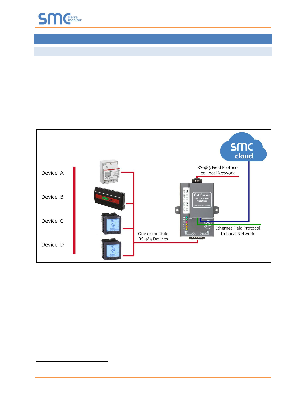
The ProtoNode is an external, high performance building automation multi-protocol gateway that is
preconfigured to automatically communicate between Weil-McLain’s products (hereafter called “device”)
connected to the ProtoNode and automatically configures them for BACnet MS/TP, BACnet/IP, Metasys
®
2
N2 by JCI, Modbus TCP/IP or LonWorks
®
3
.
It is not necessary to download any configuration files to support the required applications. The ProtoNode
is pre-loaded with tested profiles/configurations for the supported devices.
WARNING: Only use screws supplied by SMC in the holes found on the back of the unit when
attaching the optional DIN rail bracket. Use of any other screws may damage the unit.
FPC-N34 Connectivity Diagram:
2
Metasys is a registered trademark of Johnson Controls Inc.
3
LonWorks is a registered trademark of Echelon Corporation
Weil-McLain ProtoNode Start-up Guide
Page 9 of 61
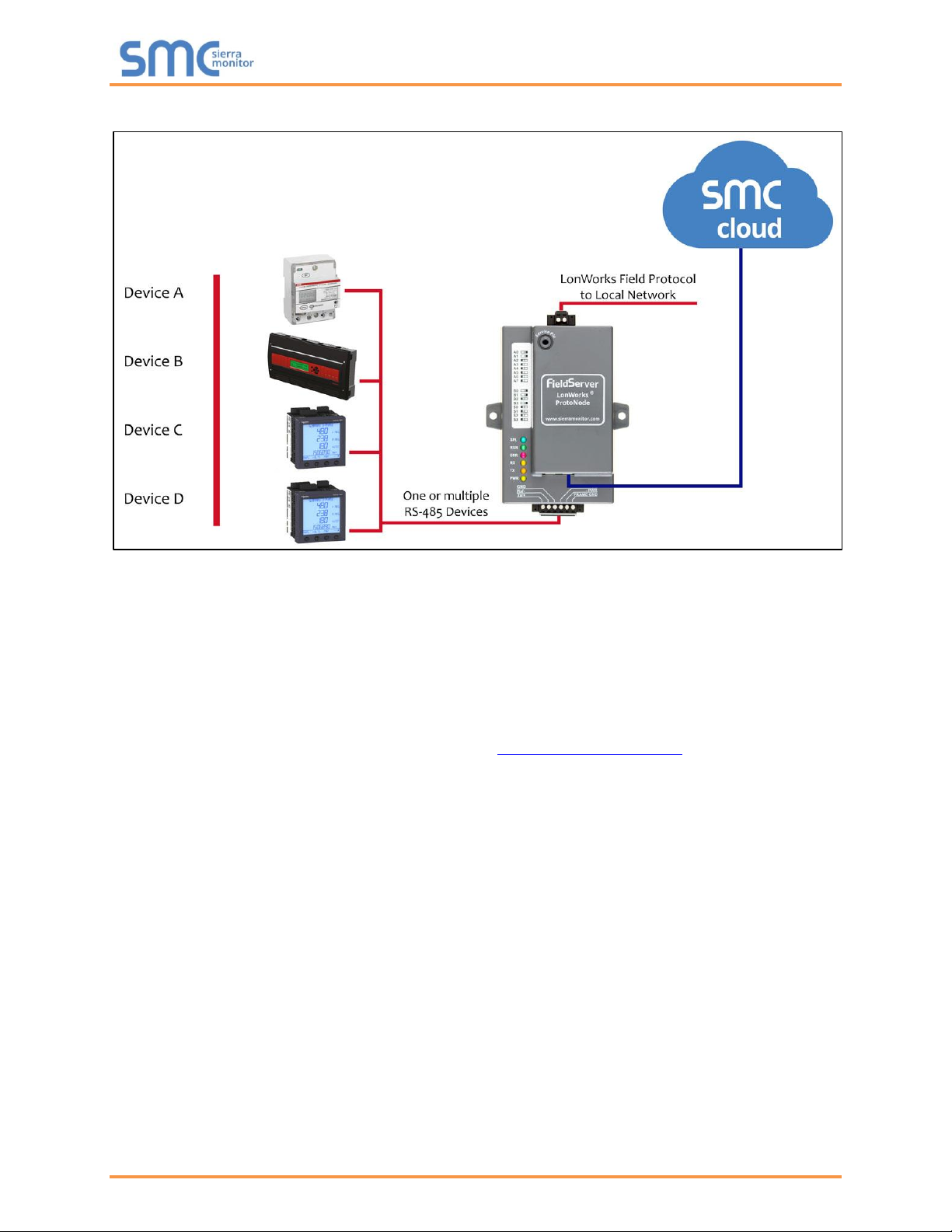
FPC-N35 Connectivity Diagram:
The ProtoNode can connect with Sierra Monitor’s SMC Cloud. The SMC Cloud allows technicians, the
OEM's support team and Sierra Monitor's support team to remotely connect to the ProtoNode. The SMC
Cloud provides the following capabilities for any registered devices in the field:
• Remotely monitor and control devices.
• Collect device data and view it on the SMC Cloud Dashboard and the SMC Smart Phone App.
• Create user defined device notifications (alarm, trouble and warning) via SMS and/or Email.
• Generate diagnostic captures (as needed for troubleshooting) without going to the site.
For more information about the SMC Cloud, refer to the SMC Cloud Start-up Guide.
Weil-McLain ProtoNode Start-up Guide
Page 10 of 61
3 SETUP FOR PROTONODE
3.1 Record Identification Data
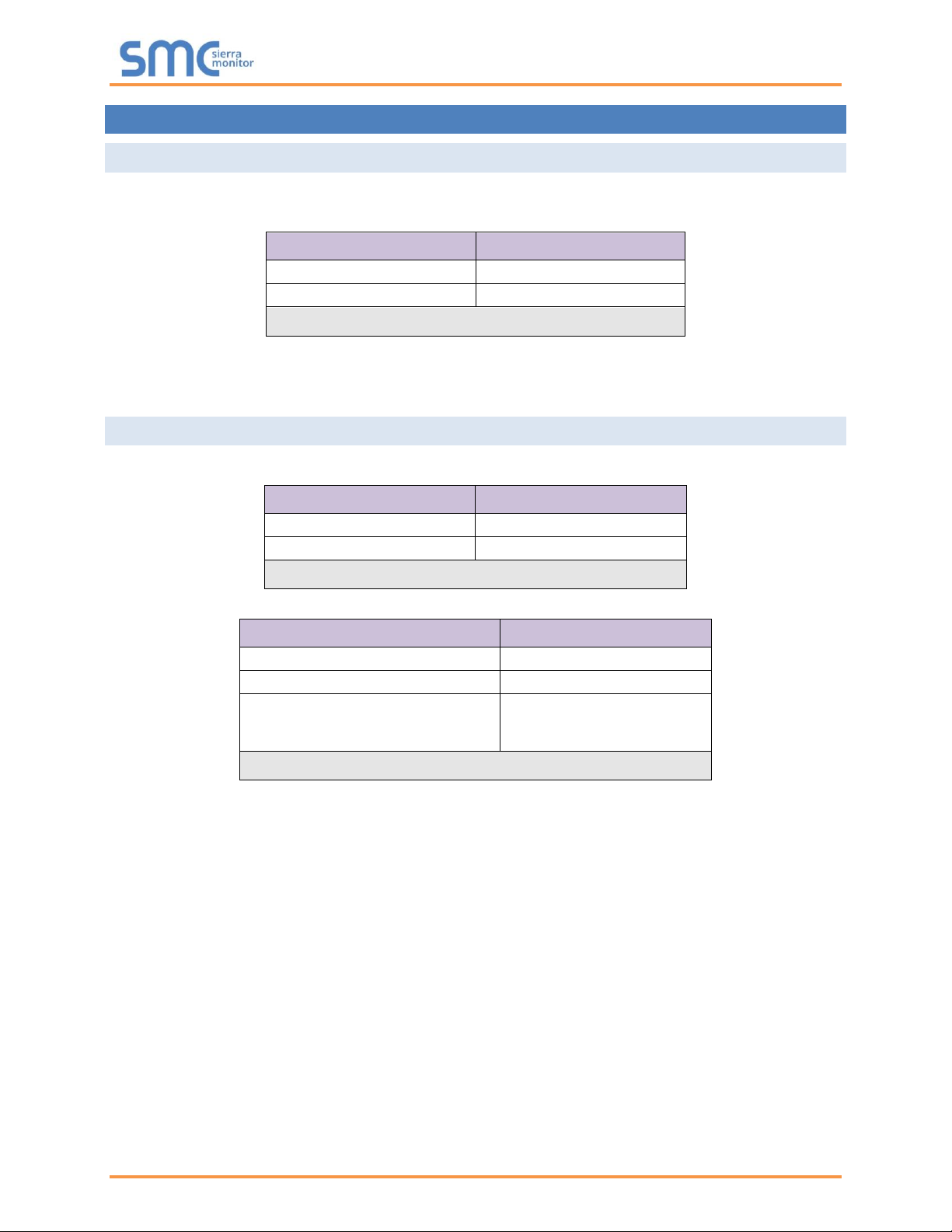
Each ProtoNode has a unique part number located on the side or the back of the unit. This number should
be recorded, as it may be required for technical support. The numbers are as follows:
Model
Part Number
ProtoNode FPC-N34
FPC-N34-0970
ProtoNode FPC-N35
FPC-N35-0991
Figure 1: ProtoNode Part Numbers
• FPC-N34 units have the following 3 ports: RS-485 + Ethernet + RS-485
• FPC-N35 units have the following 3 ports: LonWorks + Ethernet + RS-485
3.2 Point Count Capacity and Registers per Device
The total number of registers presented by the device(s) attached to the ProtoNode cannot exceed:
Part number
Total Registers
FPC-N34-0970
5,000
FPC-N35-0991
5,000
Figure 2: Supported Point Count Capacity
Devices
Registers Per Device
SlimFit 1000-2000 Series 1 (SOLA)
144
Evergreen
831
SlimFit 550-750 Series 2 & 3
SlimFit 1000-2000 Series 2
SVF Models
831
Figure 3: Registers per Device

Weil-McLain ProtoNode Start-up Guide
Page 11 of 61
3.3 Configuring Device Communications
3.3.1 Input COM Settings on Any Serial Device Connected to the ProtoNode
• Any connected serial device MUST have the same baud rate, data bits, stop bits, and
parity settings as the ProtoNode.
• Figure 4 specifies the device serial port settings required to communicate with the ProtoNode.
Port Setting
SlimFit 1000-2000
Series 1 (SOLA)
Evergreen/
SlimFit 550-750
Series 2 & 3/
SlimFit 1000-2000
Series 2/
SVF Models
Protocol
Modbus RTU
Modbus RTU
Baud Rate
38400
19200
Parity
None
None
Data Bits
8
8
Stop Bits
1
2
Figure 4: COM Settings
NOTE: The ProtoNode default setting for the Modbus RTU serial baud rate is 19200. When
connecting devices with a different baud rate (SlimFit 1000-2000 Series 1), the baud rate
must be changed via the ProtoNode Web Configurator (Section 5.5).
3.3.2 Set Node-ID for Any Device Attached to the ProtoNode
• Set Node-ID for any device attached to ProtoNode. The Node-ID needs to be uniquely assigned
between 1 and 255.
• Document the Node-ID that is assigned to any device. The Node-ID assigned is used for deriving
the Device Instance for BACnet/IP and BACnet MS/TP. (Section 3.5.2)
NOTE: The Metasys N2 and Modbus TCP/IP field protocol Node-ID is automatically set to be the
same value as the Node-ID of the device.
Weil-McLain ProtoNode Start-up Guide
Page 12 of 61
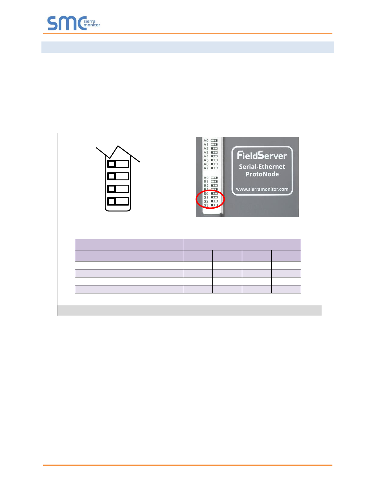
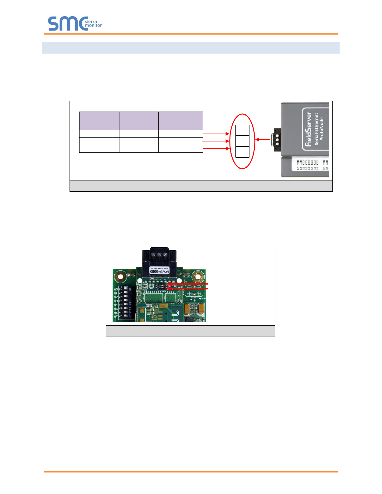
3.4 Selecting the Desired Protocol Configuration
• ProtoNode FPC-N34 units use the “S” bank of DIP switches (S0 – S3) to select the protocol
configuration.
o See the table in Figure 5 for the switch settings to select
o The OFF position is when the DIP switches are set closest to the outside of the box
• ProtoNode FPC-N35 units do not use the “S” bank DIP switches (S0 – S3) to select a field protocol.
o On ProtoNode FPC-N35 units, these switches are disabled; the field protocol is always
LonWorks
ProtoNode FPC-N34
S Bank DIP Switches
Profile
S0
S1
S2
S3
BACnet/IP
Off
Off
Off
Off
BACnet MS/TP
On
Off
Off
Off
Metasys N2
Off
On
Off
Off
Modbus TCP/IP
On
On
Off
Off
NOTE: When setting DIP switches, ensure that power to the board is OFF.
S0 – S3 DIP
Switches
S Bank DIP Switch Location
Profile Settings for ProtoNode
Figure 5: S Bank DIP Switches
S3
S2
S1
S0
Off On
Weil-McLain ProtoNode Start-up Guide
Page 13 of 61
3.5 BMS Network Settings: MAC Address, Device Instance and Baud Rate
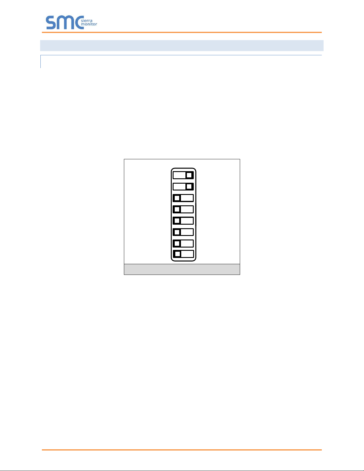
3.5.1 BACnet MS/TP (FPC-N34): Setting the MAC Address for BMS Network
• Only 1 MAC Address is set for ProtoNode regardless of how many devices are connected to
ProtoNode.
• Set the BACnet MS/TP MAC Address of the ProtoNode to a value between 1 to 127 (Master MAC
Address); this is so that the BMS front end can find ProtoNode via BACnet Auto-Discovery.
NOTE: Never set a BACnet MS/TP MAC Address of the ProtoNode to a value from 128 to 255.
Addresses from 128 to 255 are Slave Addresses and cannot be discovered by BMS front
ends that support Auto-Discovery of BACnet MS/TP devices.
• Set “A” bank DIP switches A0 – A7 to assign a MAC Address to the ProtoNode for BACnet MS/TP.
• Refer to Appendix D.1 for the complete range of MAC Addresses and DIP switch settings.
A0
A1
A2
A3
A4
A5
A6
A7
Off On
NOTE: When setting DIP switches, ensure that power to the board is OFF.
Figure 6: MAC Address DIP Switches
Weil-McLain ProtoNode Start-up Guide
Page 14 of 61
3.5.2 BACnet (FPC-N34): Calculating the Default Device Instance
• The Device Instance value is automatically generated using the following formula:
BACnet Device Instance = (Device Node ID) + (Default Node Offset)
NOTE: The default Node Offset is 50,000.
For example, if Device A has a Node ID of 1 and Device B has a Node ID of 2, then:
BACnet Device Instance A = (1) + (50000) = 50001
BACnet Device Instance B = (2) + (50000) = 50002
NOTE: The Node ID is set in Section 5.3.
• To reach a specific BACnet Device Instance result, refer to Section 6.
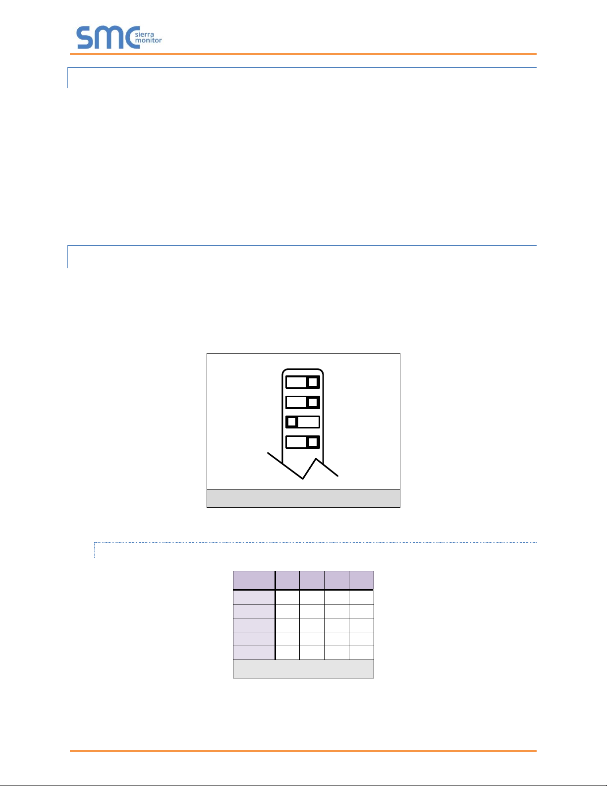
3.5.3 BACnet MS/TP (FPC-N34): Setting the Baud Rate for BMS Network
• DIP switches B0 – B3 can be used to set the field baud rate of the ProtoNode to match the baud
rate required by the BMS for BACnet MS/TP.
• The ProtoNode baud rate for Metasys N2 is set for 9600. DIP switches B0 – B3 are disabled for
Metasys N2 on the ProtoNode FPC-N34.
• DIP switches B0 – B3 are disabled on the ProtoNode FPC-N35 (LonWorks).
B0
B1
B2
B3
Off
On
NOTE: When setting DIP switches, ensure that power to the board is OFF.
3.5.3.1 Baud Rate DIP Switch Selection
Baud
B0
B1
B2
B3
9600
On
On
On
Off
19200
Off
Off
Off
On
38400*
On
On
Off
On
57600
Off
Off
On
On
76800
On
Off
On
On
Figure 8: BMS Baud Rate
* Factory default setting = 38400
Figure 7: Baud Rate DIP Switches
Weil-McLain ProtoNode Start-up Guide
Page 15 of 61
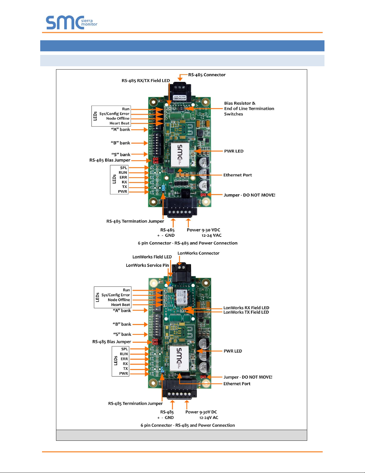
4 INTERFACING PROTONODE TO DEVICES
4.1 ProtoNode FPC-N34 and FPC-N35 Showing Connection Ports
Figure 9: ProtoNode FPC-N34 (Top) and ProtoNode FPC-N35 (Bottom)
Weil-McLain ProtoNode Start-up Guide
Page 16 of 61
4.2 Serial Device Connections to the ProtoNode
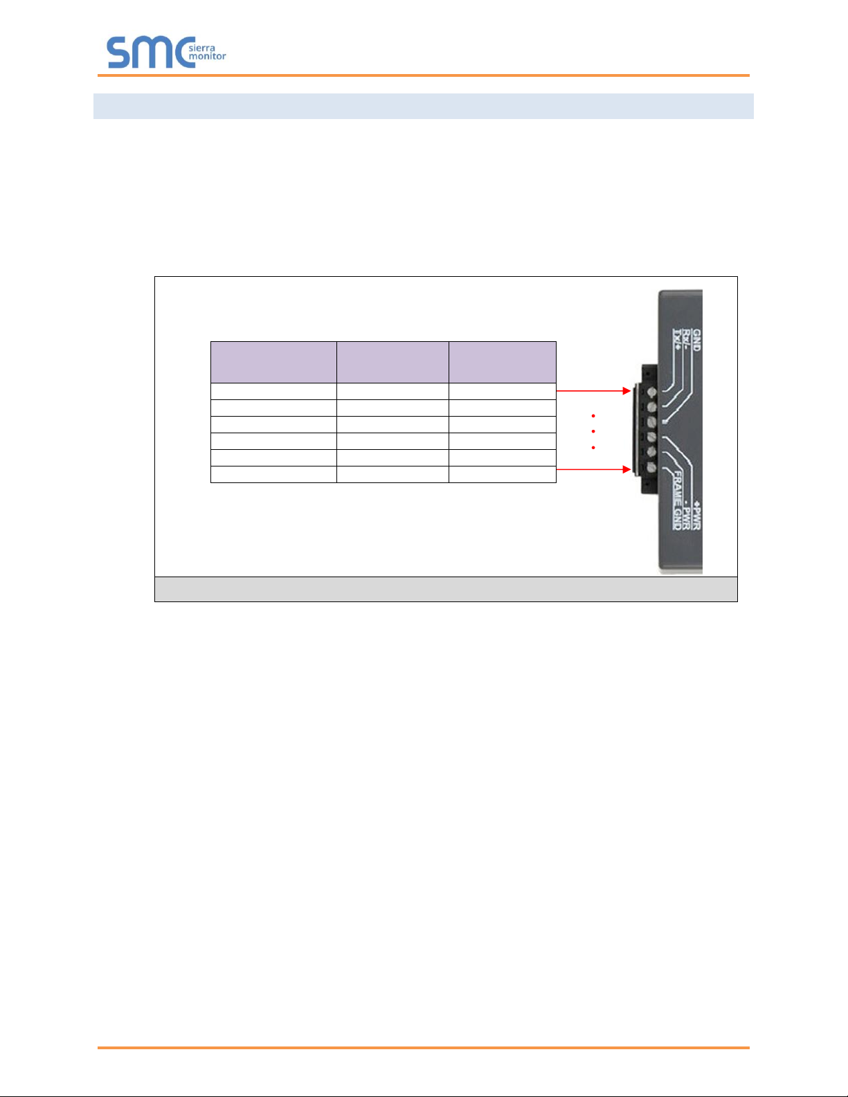
ProtoNode 6 Pin Phoenix connector:
• The 6 pin Phoenix connector is the same for ProtoNode FPC-N34 and FPC-N35 (LonWorks).
• Pins 1 through 3 are for RS-485 devices.
o Use standard grounding principles for RS-485 GND
• Pins 4 through 6 are for power. Do not connect power until Section 4.5.
Device Pins
ProtoNode Pin
#
Pin
Assignment
Pin RS-485 +
Pin 1
RS-485 +
Pin RS-485 -
Pin 2
RS-485 -
Pin GND
Pin 3
RS-485 GND
Power In (+)
Pin 4
V +
Power In (-)
Pin 5
V -
Frame Ground
Pin 6
FRAME GND
Figure 10: Device and Power Connections
Weil-McLain ProtoNode Start-up Guide
Page 17 of 61
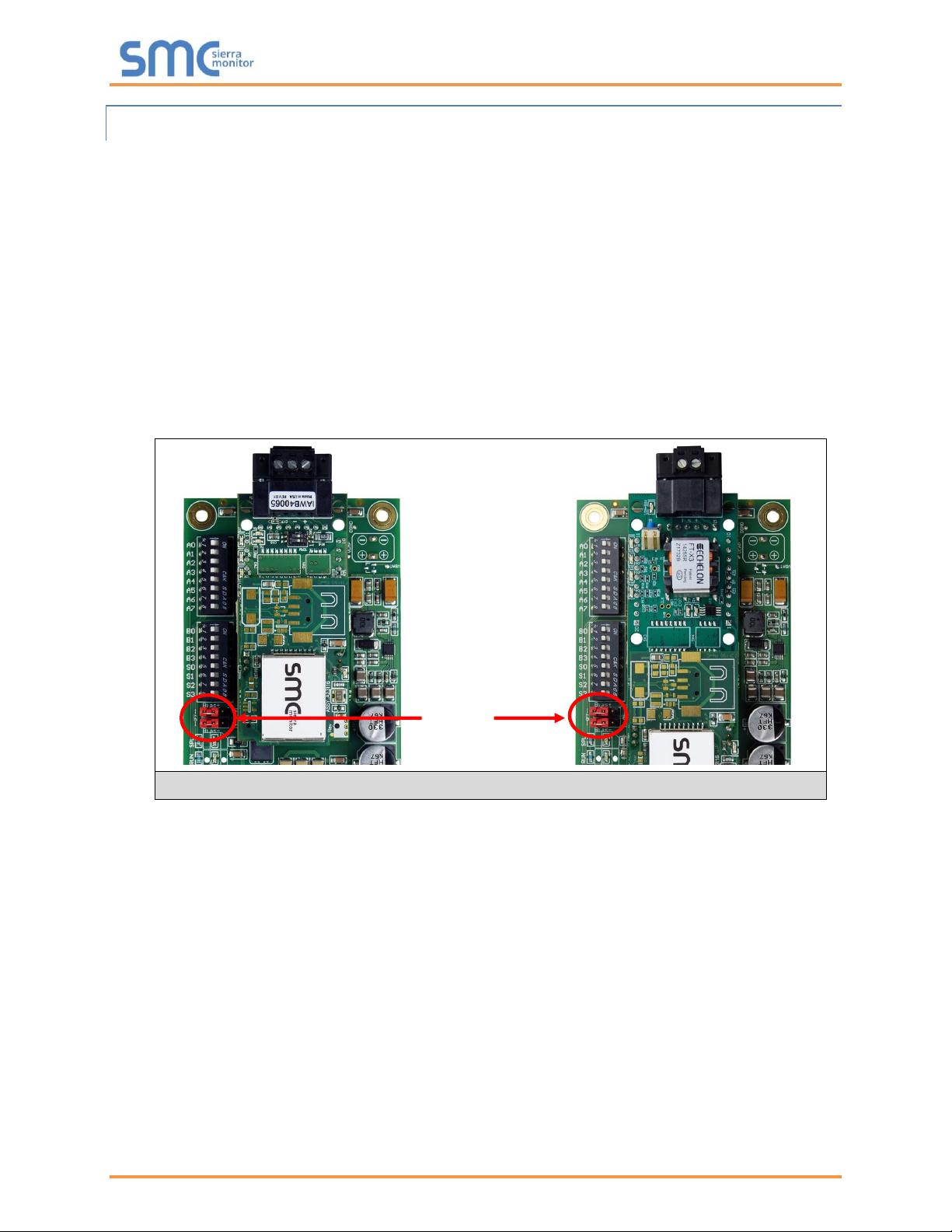
4.2.1 Biasing the RS-485 Device Network
• An RS-485 network with more than one device needs to have biasing to ensure proper
communication. The biasing only needs to be done on one device.
• The ProtoNode has 510 ohm resistors that can be used to set the biasing. The ProtoNode’s default
positions from the factory for the biasing jumpers are OFF.
• The OFF position is when the 2 red biasing jumpers straddle the 4 pins closest to the outside of
the board of the ProtoNode. (Figure 11)
• Only turn biasing ON:
o IF the BMS cannot see more than one device connected to the ProtoNode
o AND all the settings (COM settings, wiring, and DIP switches) have been checked
• To turn biasing ON, move the 2 red biasing jumpers to straddle the 4 pins closest to the inside of
the board of the ProtoNode.
RS-485 Bias
Switch
(off)
Figure 11: RS-485 Biasing Switch on the ProtoNode N34 (Left) and ProtoNode N35 (Right)
Weil-McLain ProtoNode Start-up Guide
Page 18 of 61
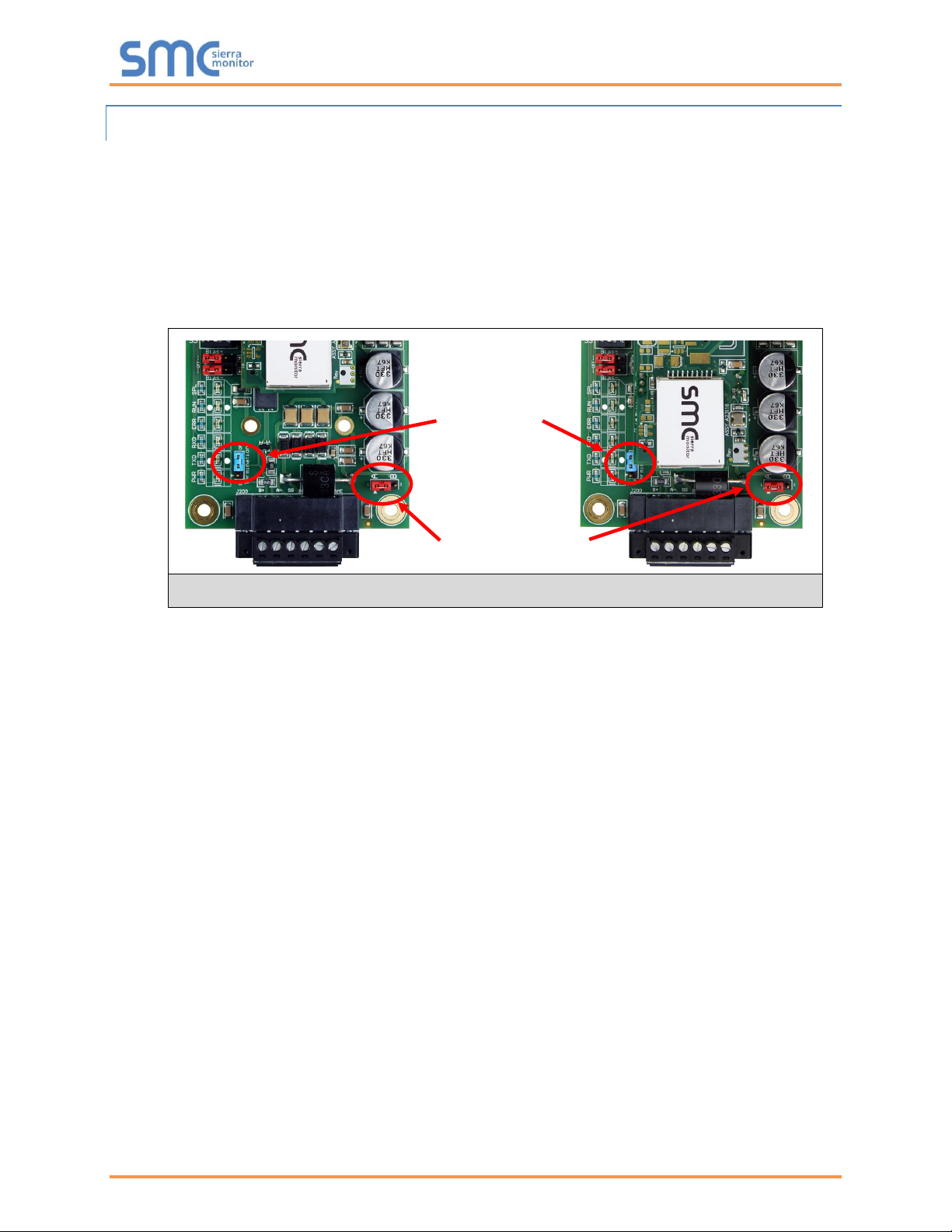
4.2.2 End of Line Termination Switch for the RS-485 Device Network
• On long RS-485 cabling runs, the RS-485 trunk must be properly terminated at each end.
• The ProtoNode has an end of line (EOL) blue jumper. The default setting for this blue EOL switch
is OFF with the jumper straddling the pins closest to the inside of the board of the ProtoNode.
o On short cabling runs the EOL switch does not to need to be turned ON
• If the ProtoNode is placed at one of the ends of the trunk, set the blue EOL jumper to the ON
position straddling the pins closest to the outside of the board of the ProtoNode.
• Always leave the single red jumper in the A position (default factory setting).
RS-485 EOL
Switch
(off)
Leave in Position A
Figure 12: RS-485 End-Of-Line Termination Switch on the ProtoNode N34 (Left) and
ProtoNode N35 (Right)
Weil-McLain ProtoNode Start-up Guide
Page 19 of 61
4.3 Serial Network (FPC-N34): Wiring Field Port to RS-485 Network
• Connect the RS-485 network wires to the 3-pin RS-485 connector on ProtoNode FPC-N34 as
shown below in Figure 13.
o Use standard grounding principles for RS-485 GND
• See Section 5.4 for information on connecting to an Ethernet network.
• If the ProtoNode is the last device on the trunk, then the end of line (EOL) termination switch needs
to be enabled. See Figure 14 for the orientation of switch positions referenced below.
o The default setting from the factory is OFF (switch position = right side)
o To enable the EOL termination, turn the EOL switch ON (switch position = left side)
• If more than one RS-485 device is connected to the network, then the field bias resistor switch
needs to be enabled to ensure proper communication. See Figure 14 for the orientation of switch
positions referenced below.
o The default factory setting is OFF (switch position = right side)
o To enable biasing, turn the bias switch ON (switch position = left side)
NOTE: Biasing only needs to be enabled on one device. The ProtoNode has 510 ohm resistors
that are used to set the biasing.
BMS
Wiring
ProtoNode
Pin #
Pin
Assignment
RS-485 +
Pin 1
RS-485 +
RS-485 -
Pin 2
RS-485 -
-
Pin 3
RS-485 GND
Bias Resistor Switch
End of Line Switch
Figure 14: RS-485 EOL & Bias Resistor Switches
Figure 13: Connection from ProtoNode to RS-485 Field Network
G
-

Weil-McLain ProtoNode Start-up Guide
Page 20 of 61
4.4 LonWorks (FPC-N35): Wiring LonWorks Devices to the LonWorks Terminal
• Wire the LonWorks device network to the ProtoNode LonWorks Terminal.
o Use approved cable per the FT-10 installation guidelines
• LonWorks has no polarity.
Figure 15: LonWorks Terminal

Weil-McLain ProtoNode Start-up Guide
Page 21 of 61
4.5 Power-Up ProtoNode
Check power requirements in the table below:
Power Requirement for ProtoNode External Gateway
Current Draw Type
ProtoNode Family
12VDC/AC
24VDC/AC
30VDC
FPC – N34 (Typical)
170mA
100mA
80mA
FPC – N34 (Maximum)
240mA
140mA
100mA
FPC – N35 (Typical)
210mA
130mA
90mA
FPC – N35 (Maximum)
250mA
170mA
110mA
NOTE: These values are ‘nominal’ and a safety margin should be added to the power supply of
the host system. A safety margin of 25% is recommended.
Figure 16: Required Current Draw for the ProtoNode
Apply power to the ProtoNode as shown below in Figure 17. Ensure that the power supply used complies
with the specifications provided in Appendix E.1.
• ProtoNode accepts either 9-30VDC or 12-24VAC on pins 4 and 5.
• Frame GND should be connected.
Power to
ProtoNode
ProtoNode
Pin #
Pin
Assignment
Power In (+)
Pin 4
V +
Power In (-)
Pin 5
V -
Frame Ground
Pin 6
FRAME GND
Figure 17: Power Connections

Weil-McLain ProtoNode Start-up Guide
Page 22 of 61
5 USE THE PROTONODE WEB CONFIGURATOR TO SETUP THE GATEWAY
5.1 Connect the PC to the ProtoNode via the Ethernet Port
First, connect a Cat-5 Ethernet cable (straight through or cross-over) between the local PC and ProtoNode.
There are two methods to access the ProtoNode via Ethernet connection, either by changing the
subnet of the connected PC (Section 5.1.1) or using the FieldServer Toolbox to change the IP
Address of the ProtoNode (Section 5.1.2).
NOTE: Only perform one method or the other.
5.1.1 Changing the Subnet of the Connected PC
The default IP Address for the ProtoNode is 192.168.1.24, Subnet Mask is 255.255.255.0. If the PC and
ProtoNode are on different IP networks, assign a static IP Address to the PC on the 192.168.1.xxx network.
For Windows 10:
• Find the search field in the local computer’s taskbar (usually to the right of the windows icon )
and type in “Control Panel”.
• Click “Control Panel”, click “Network and Internet” and then click “Network and Sharing Center”.
• Click “Change adapter settings” on the left side of the window.
• Right-click on “Local Area Connection” and select “Properties” from the dropdown menu.
• Highlight and then click the Properties button.
• Select and enter a static IP Address on the same subnet. For example:
• Click the Okay button to close the Internet Protocol window and the Close button to close the
Ethernet Properties window.
Ethernet Port
Figure 18: Ethernet Port Location

Weil-McLain ProtoNode Start-up Guide
Page 23 of 61
5.1.2 Changing the IP Address of the ProtoNode with FieldServer Toolbox
• Ensure that FieldServer Toolbox is loaded onto the local PC. Otherwise, download the
FieldServer-Toolbox.zip via the Sierra Monitor website’s Software Downloads.
• Extract the executable file and complete the installation.
• Double click on the FS Toolbox Utility and click Discover Now on the splash page.
• Find the desired gateway and click the Configure Device button (gear icon) to the right of the
gateway information.
NOTE: If connectivity status is green, then the IP Address doesn’t need to be changed (the
ProtoNode is already on the same subnet). Skip to the next section.
• Select Network Settings in the Configure Device window.
• Modify the IP Address (N1 IP Address field) of the gateway Ethernet port.
o Change additional fields as needed
NOTE: If the gateway is connected to a router, the Default Gateway field of the gateway should be
set to the IP Address of the connected router.
NOTE: Do not change the DHCP Server State (N1 DHCP Server State field).
NOTE: If DNS settings are unknown, set DNS1 to “8.8.8.8” and DNS2 to “8.8.4.4”.
• Click Update IP Settings, then click on the “Change and restart” button to reboot the gateway and
activate the new IP Address. See the FieldServer Toolbox and GUI Manual for more information.

Weil-McLain ProtoNode Start-up Guide
Page 24 of 61
5.2 Connecting to the ProtoNode Web Configurator
After setting a local PC on the same subnet as the ProtoNode (Section 5.1), open a web browser on the
PC and enter the IP Address of the ProtoNode; the default address is 192.168.1.24.
NOTE: If the IP Address of the ProtoNode was changed, the assigned IP Address can be
discovered using the FS Toolbox utility. See Appendix A.1 for instructions.
5.3 Selecting Profiles for Devices Connected to ProtoNode
NOTE: If Modbus TCP/IP was selected in Section 3.4 for the Field/BMS protocol, skip this section.
Device profiles are NOT used for Modbus TCP/IP.
• In the Web Configurator, the Active Profiles are shown below the Configuration Parameters.
• The Active Profiles section lists the currently active device profiles, including previous Web
Configurator additions. This list is empty for new installations, or after clearing all configurations.
(Figure 19)
Figure 19: Web Configurator Showing no Active Profiles

Weil-McLain ProtoNode Start-up Guide
Page 25 of 61
• To add an active profile to support a device, click the Add button under the Active Profiles heading.
Select a profile from the drop-down menu field that appears underneath the Current profile column.
(Figure 20)
• For every device that is added, assign a unique Node-ID. This specification must match the device’s
network settings.
NOTE: If multiple devices are connected to the ProtoNode, set the BACnet Virtual Server Nodes
field to “Yes”; otherwise leave the field on the default “No” setting.
• Once the Profile for the device has been selected from the drop-down list, enter the value of the
device’s Node-ID which was assigned in Section 3.3.2.
• Then press the “Submit” button to add the Profile to the list of devices to be configured.
• Repeat this process until all the devices have been added.
• Completed additions are listed under “Active profiles” as shown in Figure 21.
5.3.1 Verify Device Communications
• Check that TX and RX LEDs are rapidly flashing. See Appendix A.4 for information and images.
• Confirm the software shows communication without errors. Go to Appendix A.2 for instructions.
Figure 20: Web Configurator Showing Available Profile Selection
Figure 21: Web Configurator Showing Active Profile Additions

Weil-McLain ProtoNode Start-up Guide
Page 26 of 61
5.4 Ethernet Network: Setting IP Address for the Field Network
• After setting a local PC to the same subnet as the ProtoNode (Section 5.1), open a web browser
on the PC and enter the IP Address of the ProtoNode; the default address is 192.168.1.24.
• The Web Configurator is displayed as the landing page. (Figure 22)
Figure 22: Web Configurator Screen with Active Profiles

Weil-McLain ProtoNode Start-up Guide
Page 27 of 61
• To access the FS-GUI, click on the “Diagnostics & Debugging” button in the bottom right corner of
the page.
• From the FS-GUI landing page, click on “Setup” to expand the navigation tree and then select
“Network Settings” to access the IP Settings menu. (Figure 23)
• Modify the IP Address (N1 IP Address field) of the ProtoNode Ethernet port.
• If necessary, change the Netmask (N1 Netmask field).
• If necessary, change the IP Gateway (Default Gateway field).
NOTE: If the ProtoNode is connected to a managed switch/router, the IP Gateway of the
ProtoNode should be set to the IP Address of that managed switch/router.
• Click the “System Restart” button at the bottom of the page to apply changes and restart the
ProtoNode.
• Unplug Ethernet cable from PC and connect it to the network switch or router.
• Record the IP Address assigned to the ProtoNode for future reference.
NOTE: The FieldPoP™ button (see Figure 23) allows users to connect to the SMC
Cloud, Sierra Monitor’s device cloud solution for IIoT. The SMC Cloud enables secure
remote connection to field devices through a FieldServer and its local applications for
configuration, management, maintenance. For more information about the SMC Cloud,
refer to the SMC Cloud Start-up Guide.
Figure 23: Changing IP Address via FS-GUI

Weil-McLain ProtoNode Start-up Guide
Page 28 of 61
5.5 Change ProtoNode COM Settings
• In the Web Configurator, the ProtoNode COM Settings are the first parameters displayed.
NOTE: The ProtoNode default setting for the Modbus RTU serial baud rate is 19200 and the
default stop bits setting is 1. When connecting devices with different baud rate and stop
bits settings (SlimFit 1000-2000 Series 1), these values must be changed via the
ProtoNode Web Configurator to match the device.
• Change the ProtoNode COM Settings if needed. See Figure 25 for the correct device settings.
Device Settings
SlimFit 1000-2000
Series 1 (SOLA)
Evergreen/
SlimFit 550-750
Series 2 & 3/
SlimFit 1000-2000
Series 2/
SVF Models
Baud Rate
38400
19200
Parity
None
None
Data Bits
8
8
Stop Bits
1
2
Figure 25: Device COM Settings
• If new values are entered in the text field, click Submit then reset the ProtoNode.
Figure 24: Web Configurator ProtoNode COM Settings

Weil-McLain ProtoNode Start-up Guide
Page 29 of 61
6 BACNET: SETTING NODE_OFFSET TO ASSIGN SPECIFIC DEVICE
INSTANCES
• After setting a local PC to the same subnet as the ProtoNode (Section 5.1), open a web browser
on the PC and enter the IP Address of the ProtoNode.
o If the IP Address of the ProtoNode has been changed by previous configuration, the assigned
IP Address must be gathered from the network administrator
o The Web Configurator is displayed as the landing page
• Node_Offset field shows the current value (default = 50,000).
o The values allowed for a BACnet Device Instance can range from 1 to 4,194,303
• To assign a specific Device Instance (or range); change the Node_Offset value as needed using
the calculation below:
Device Instance (desired) = Node_Offset + Node_ID
For example, if the desired Device Instance for the device 1 is 50,001 and the following is true:
- Device 1 has a Node-ID of 1
- Device 2 has a Node-ID of 22
- Device 3 has a Node-ID of 33
Then plug the device 1’s information into the formula to find the desired Node_Offset:
50,001 = Node_Offset + 1
➢ 50,000 = Node_Offset
Once the Node_Offset value is input, it will be applied to all devices as shown below:
- Device 1 Instance = 50,000 + Node_ID = 50,000 + 1 = 50,001
- Device 2 Instance = 50,000 + Node_ID = 50,000 + 22 = 50,022
- Device 3 Instance = 50,000 + Node_ID = 50,000 + 33 = 50,033
• Click “Submit” once the desired value is entered.
Figure 27: Active Profiles
Figure 26: Web Configurator Node Offset Field

Weil-McLain ProtoNode Start-up Guide
Page 30 of 61
7 HOW TO START THE INSTALLATION OVER: CLEARING PROFILES
• After setting a local PC to the same subnet as the ProtoNode (Section 5.1), open a web browser
on the PC and enter the IP Address of the ProtoNode; the default address is 192.168.1.24.
• If the IP Address of the ProtoNode has been changed by previous configuration, the assigned IP
Address must be gathered from the network administrator.
• The Web Configurator is displayed as the landing page.
• At the bottom-left of the page, click the “Clear Profiles and Restart” button.
• Once restart is complete, all past profiles discovered and/or added via Web configurator are
deleted. The unit can now be reinstalled.

Weil-McLain ProtoNode Start-up Guide
Page 31 of 61
8 LONWORKS (FPC-N35): COMMISSIONING PROTONODE ON A LONWORKS
NETWORK
Commissioning may only be performed by the LonWorks administrator.
8.1 Commissioning ProtoNode FPC-N35 on a LonWorks Network
During the commissioning process, the LonWorks administrator may prompt the user to hit the service pin
on the ProtoNode FPC-N35 at a specific point (this step occurs at different points of the commissioning
process for each LonWorks network management tool).
• If an XIF file is required, see steps in Section 8.1.1 to generate XIF.
8.1.1 Instructions to Upload XIF File from ProtoNode FPC-N35 Using Browser
• Connect a Cat-5 Ethernet cable (straight through or cross-over) between the PC and ProtoNode.
• The default IP Address for the ProtoNode is 192.168.1.24, Subnet Mask is 255.255.255.0. If the
PC and ProtoNode are on different IP networks, assign a static IP Address to the PC on the
192.168.1.xxx network.
For Windows 10:
• Find the search field in the local computer’s taskbar (usually to the right of the windows icon )
and type in “Control Panel”.
• Click “Control Panel”, click “Network and Internet” and then click “Network and Sharing Center”.
• Click “Change adapter settings” on the left side of the window.
• Right-click on “Local Area Connection” and select “Properties” from the dropdown menu.
• Highlight and then click the Properties button.
• Select and enter a static IP Address on the same subnet. For example:
• Click the Okay button to close the Internet Protocol window and the Close button to close the
Ethernet Properties window.
Figure 28: LonWorks Service Pin Location

Weil-McLain ProtoNode Start-up Guide
Page 32 of 61
• Open a web browser and go to the following address: [IP Address of ProtoNode]/fserver.xif
o Example: 192.168.1.24/fserver.xif
• If the web browser prompts to save the file, save the file onto the PC. If the web browser displays
the xif file as a web page, save the file onto the local PC as “fserver.xif”.
Figure 29: Sample of Fserver.XIF File Generated

Weil-McLain ProtoNode Start-up Guide
Page 33 of 61
Appendix A. Troubleshooting
Lost or Incorrect IP Address
• Ensure that FieldServer Toolbox is loaded onto the local PC. Otherwise, download the
FieldServer-Toolbox.zip via the Sierra Monitor website’s Software Downloads.
• Extract the executable file and complete the installation.
• Connect a standard Cat-5 Ethernet cable between the user’s PC and ProtoNode.
• Double click on the FS Toolbox Utility and click Discover Now on the splash page.
• Check for the IP Address of the desired gateway.
• If correcting the IP Address of the gateway: click the settings icon on the same row as the
gateway, then click Network Settings, change the IP Address and click Update IP Settings to save.
Ethernet Port
Figure 30: Ethernet Port Location

Weil-McLain ProtoNode Start-up Guide
Page 34 of 61
Viewing Diagnostic Information
• Type the IP Address of the ProtoNode into the web browser or use the FieldServer Toolbox to
connect to the ProtoNode.
• Click on Diagnostics and Debugging Button, then click on view, and then on connections.
• If there are any errors showing on the Connection page, refer to Appendix A.3 for the relevant
wiring and settings.
Figure 31: Error Messages Screen

Weil-McLain ProtoNode Start-up Guide
Page 35 of 61
Check Wiring and Settings
• No COMS on Modbus RTU side. If the Tx/Rx LEDs are not flashing rapidly then there is a COM
issue. To fix this, check the following:
o Visual observations of LEDs on the ProtoNode (Appendix A.4)
o Check baud rate, parity, data bits, stop bits
o Check device address
o Verify wiring
o Verify device is connected to the same subnet as the ProtoNode
o Verify the Modbus device(s) were listed in the Web Configurator (Section 5.2)
• Field COM problems:
o If Ethernet protocols are used, observe Ethernet LEDs on the ProtoNode (Appendix A.4)
o Check dipswitch settings (using correct baud rate and device instance)
o Verify IP Address setting
o Verify wiring
NOTE: If the problem persists, a Diagnostic Capture needs to be taken and sent to support.
(Appendix A.5)

Weil-McLain ProtoNode Start-up Guide
Page 36 of 61
LED Diagnostics for Communications Between ProtoNode and Devices
See the diagram below for ProtoNode FPC-N34 and FPC-N35 LED Locations.
Tag
Description
SPL
The SPL LED will light if the unit is not getting a response from one or more of the configured devices.
For LonWorks units, LED will light until the unit is commissioned on the LonWorks network.
RUN
The RUN LED will start flashing 20 seconds after power indicating normal operation.
ERR
A steady red light will indicate there is a system error on the unit. If this occurs, immediately report the
related “system error” shown in the error screen of the FS-GUI interface to support for evaluation.
RX
The RX LED will flash when a message is received on the serial port on the 6-pin connector.
If the serial port is not used, this LED is non-operational.
TX
The TX LED will flash when a message is sent on the serial port on the 6-pin connector.
If the serial port is not used, this LED is non-operational.
PWR
This is the power light. It should always show a steady green light when powered.
Figure 32: Diagnostic LEDs
Diagnostic LEDs

Weil-McLain ProtoNode Start-up Guide
Page 37 of 61
Take a FieldServer Diagnostic Capture
When there is a problem on-site that cannot easily be resolved, perform a diagnostic capture before
contacting support so that support can quickly solve the problem. There are two methods for taking
diagnostic captures:
• FieldServer Toolbox:
This method requires installation of the FS Toolbox program. A FS Toolbox diagnostic capture
takes a snapshot of the loaded configuration files and a log of all the communications on the
serial ports over a specified period of time. If the problem occurs over an Ethernet connection,
then take a Wire Shark capture.
• Gateway’s FS-GUI Page:
This method doesn’t require downloading software. The diagnostic capture utilities are embedded
in the FS-GUI web interface. Starting a diagnostic capture takes a snapshot of the loaded
configuration files and a log of all the communications over a specified period of time. This works
for both serial and Ethernet connections.
NOTE: The information in the zipped files contains everything support needs to quickly resolve
problems that occur on-site.
Appendix A.5.1. Using the FieldServer Toolbox
Once the Diagnostic Capture is complete, email it to technical support. The Diagnostic Capture will
accelerate diagnosis of the problem.
• Ensure that FieldServer Toolbox is loaded onto the local PC. Otherwise, download the
FieldServer-Toolbox.zip via the Sierra Monitor website’s Software Downloads.
• Extract the executable file and complete the installation.
• Connect a standard Cat-5 Ethernet cable between the PC and ProtoNode.
• Double click on the FS Toolbox Utility.
Ethernet Port
Figure 33: Ethernet Port Location

Weil-McLain ProtoNode Start-up Guide
Page 38 of 61
• Step 1: Take a Log
o Click on the diagnose icon of the desired device
o Ensure “Full Diagnostic" is selected (this is the default)
NOTE: If desired, the default capture period can be changed.

Weil-McLain ProtoNode Start-up Guide
Page 39 of 61
o Click on “Start Diagnostic”
o When the capture period is finished, the “Diagnostic Test Complete” window will appear
• Step 2: Send Log
o Once the diagnostic test is complete, a .zip file is saved on the PC
o Choose “Open” to launch explorer and have it point directly at the correct folder
o Send the diagnostic zip file to wmtechnicalservices@weil-mclain.com

Weil-McLain ProtoNode Start-up Guide
Page 40 of 61
Appendix A.5.2. Using FS-GUI
Diagnostic Capture via FS-GUI is only available on FieldServers with a bios updated/released on November
2017 or later. Completing a Diagnostic Capture through the FieldServer allows network connections (such
as Ethernet and Wi-Fi) to be captured.
Once the Diagnostic Capture is complete, email it to technical support. The Diagnostic Capture will
accelerate diagnosis of the problem.
• Open the FieldServer FS-GUI page.
• Click on Diagnostics in the Navigation panel.
• Go to Full Diagnostic and select the capture period.
• Click the Start button under the Full Diagnostic heading to start the capture.
o When the capture period is finished, a Download button will appear next to the Start button
• Click Download for the capture to be downloaded to the local PC.
• Send the diagnostic zip file to wmtechnicalservices@weil-mclain.com.
NOTE: Diagnostic captures of BACnet MS/TP communication are output in a “.PCAP” file
extension which is compatible with Wireshark.

Weil-McLain ProtoNode Start-up Guide
Page 41 of 61
Appendix B. Additional Information
Update Firmware
To load a new version of the firmware, follow these instructions:
1. Extract and save the new file onto the local PC.
2. Open a web browser and type the IP Address of the FieldServer in the address bar.
o Default IP Address is 192.168.1.24
o Use the FS Toolbox utility if the IP Address is unknown (Appendix A.1)
3. Click on the “Diagnostics & Debugging” button.
4. In the Navigation Tree on the left hand side, do the following:
a. Click on “Setup”
b. Click on “File Transfer”
c. Click on the “General” tab
5. In the General tab, click on “Choose Files” and select the web.img file extracted in step 1.
6. Click on the orange “Submit” button.
7. When the download is complete, click on the “System Restart” button.
BACnet: Setting Network_Number for More Than One ProtoNode on the Subnet
For both BACnet MS/TP and BACnet/IP, if more than one ProtoNode is connected to the same subnet,
they must be assigned unique Network_Number values.
On the main Web Configuration screen, update the BACnet Network Number field and click submit. The
default value is 50.
Figure 34: Web Configurator – Network Number Field

Weil-McLain ProtoNode Start-up Guide
Page 42 of 61
Securing ProtoNode with Passwords
Access to the ProtoNode can be restricted by enabling a password on the FS-GUI Passwords page –
click Setup and then Passwords in the navigation panel. There are 2 access levels defined by 2 account
names: Admin and User.
• The Admin account has unrestricted access to the ProtoNode.
• The User account can view any ProtoNode information but cannot make any changes or restart
the ProtoNode.
The password needs to be a minimum of eight characters and is case sensitive.
If the password is lost, click cancel on the password authentication popup window, and email the
password recovery token to technical support to receive a temporary password from the support team.
Access the ProtoNode to set a new password.
Figure 35: FS-GUI Passwords Page
Figure 36: Password Recovery Page

Weil-McLain ProtoNode Start-up Guide
Page 43 of 61
Appendix C. Vendor Information – Weil-McLain
NOTE: All Modbus TCP/IP registers are the same as the Modbus RTU registers for the serial
device. If this point list is needed, contact Weil-McLain technical support. The Modbus
TCP/IP node address of the device is also the same as the Modbus RTU node address.
SlimFit 1000-2000 Series 1 (SOLA) Modbus RTU Mappings to BACnet, Metasys
N2 and LonWorks
Point Name
BACnet
Object
Type
BACnet
Object
ID
N2
Data
Type
N2
Address
LonWorks Name
LonWorks SNVT
4-20mA Remote Control Input Status
AV
1
AO 1 nvoRemCtInSt_XXX
SNVT_count_f
Active CH Setpoint
AV
2
AO 2 nvoActCHSP_XXX
SNVT_temp_p
Active DHW Setpoint Status
AV
3
AO 3 nvoAcDHWSPSt_XXX
SNVT_temp_p
Active LL Operating Point Status
AV
4
AO 4 nvoALLOpPtSt_XXX
SNVT_temp_p
Active LL Setpoint Status
AV
5
AO 5 nvoActLLSPS_XXX
SNVT_temp_p
Active System Operating Point Status
AV
6
AO 6 nvoASyOpPtSt_XXX
SNVT_temp_p
Active System Setpoint Status
AV
7
AO 7 nvoAcSysSPSt_XXX
SNVT_temp_p
Alarm Record 1 Status
AV
8
AO 8 nvoAlmRec1St_XXX
SNVT_count_f
Alarm Record 2 Status
AV
9
AO 9 nvoAlmRec2St_XXX
SNVT_count_f
Alarm Record 3 Status
AV
10
AO
10
nvoAlmRec3St_XXX
SNVT_count_f
Alarm Record 4 Status
AV
11
AO
11
nvoAlmRec4St_XXX
SNVT_count_f
Alarm Record 5 Status
AV
12
AO
12
nvoAlmRec5St_XXX
SNVT_count_f
Annunciator First Out Status
AV
13
AO
13
nvoAn1stOtSt_XXX
SNVT_count_f
Auxiliary 2 Pump Cycle Count
AV
14
AO
14
nvoAx2PpCyCt_XXX
SNVT_count_f
Auxiliary 2 Pump Cycle Count Status
AV
15
AO
15
nvoAx2PCyCSt_XXX
SNVT_count_f
Auxiliary Pump Cycle Count
AV
16
AO
16
nvoAxPmpCyCt_XXX
SNVT_count_f
Auxiliary Pump Cycle Count Status
AV
17
AO
17
nvoAxPpCyCSt_XXX
SNVT_count_f
Boiler Pump Cycle Count
AV
18
AO
18
nvoBlPmpCyCt_XXX
SNVT_count_f
Boiler Pump Cycle Count Status
AV
19
AO
19
nvoBlPpCyCSt_XXX
SNVT_count_f
Burner Control State Status
AV
20
AO
20
nvoBrnCtStSt_XXX
SNVT_count_f
Burner Control Status
AV
21
AO
21
nvoBrnCtlSt_XXX
SNVT_count_f
Burner Cycle Count
AV
22
AO
22
nvoBrnCycCnt_XXX
SNVT_count_f
Burner Cycle Count Status
AV
23
AO
23
nvoBrnCyCtSt_XXX
SNVT_count_f
Burner Run Time
AV
24
AO
24
nvoBrnRnTme_XXX
SNVT_time_hour
Burner Run Time Status
AV
25
AO
25
nvoBrnRnTmSt_XXX
SNVT_time_hour
CH Burner Demand Status
AV
26
AO
26
nvoCHBrnDmSt_XXX
SNVT_count_f
CH Heat Demand Status
AV
27
AO
27
nvoCHHtDemSt_XXX
SNVT_count_f
CH ODR Low Water Temperature (W)
AV
28
AO
28
nvi/nvoCHODLoWtT_XXX
SNVT_temp_p
CH ODR Low Water Temperature Status
AV
29
AO
29
nvoCHODLoWTS_XXX
SNVT_temp_p
CH ODR Max Outdoor Temperature (W)
AV
30
AO
30
nvi/nvoCHODMxWtT_XXX
SNVT_temp_p
CH ODR Max Outdoor Temperature Status
AV
31
AO
31
nvoCHODMxWTS_XXX
SNVT_temp_p
CH ODR Min Outdoor Temp (W)
AV
32
AO
32
nvi/nvoCHODMnWtT_XXX
SNVT_temp_p
CH ODR Min Outdoor Temp Status
AV
33
AO
33
nvoCHODMnWTS_XXX
SNVT_temp_p
CH Pump Cycle Count
AV
34
AO
34
nvoCHPmpCyCt_XXX
SNVT_count_f
CH Pump Cycle Count Status
AV
35
AO
35
nvoCHPCyCtSt_XXX
SNVT_count_f
CH Requested Rate Status
AV
36
AO
36
nvoCHReqRtSt_XXX
SNVT_lev_percent
CH Setpoint (W)
AV
37
AO
37
nvi/nvoCH_SP_XXX
SNVT_temp_p
CH Setpoint Status
AV
38
AO
38
nvoCH_SPStat_XXX
SNVT_count_f
CH Setpoint Source Status
AV
39
AO
39
nvoCHSPSrcSt_XXX
SNVT_temp_p
CH Status
AV
40
AO
40
nvoCH_Status_XXX
SNVT_count_f
CH Time of Day Setpoint (W)
AV
41
AO
41
nvi/nvoCH_TOD_SP_XXX
SNVT_temp_p
CH Time of Day Setpoint Status
AV
42
AO
42
nvoCHTODSPSt_XXX
SNVT_temp_p
Controller Cycle Count Status
AV
43
AO
43
nvoCtCycCtSt_XXX
SNVT_count_f
Controller Run Time Status
AV
44
AO
44
nvoCtRunTmSt_XXX
SNVT_time_hour
Demand Source Status
AV
45
AO
45
nvoDemSrcSt_XXX
SNVT_count_f
DHW Status
AV
46
AO
46
nvoDHWStatus_XXX
SNVT_count_f
DHW Burner Demand Status
AV
47
AO
47
nvoDHWBrDmSt_XXX
SNVT_count_f
DHW Heat Demand Status
AV
48
AO
48
nvoDHWHtDmSt_XXX
SNVT_count_f
DHW Priority Count Status
AV
49
AO
49
nvoDHWPrCtSt_XXX
SNVT_count_f
DHW Pump Cycle Count
AV
50
AO
50
nvoDHWPpCyCt_XXX
SNVT_count_f
DHW Pump Cycle Count Status
AV
51
AO
51
nvoDHWPCyCtS_XXX
SNVT_count_f
DHW Sensor Status
AV
52
AO
52
nvoDHWSenSta_XXX
SNVT_temp_p
DHW Setpoint
AV
53
AO
53
nvoDHW_SP_XXX
SNVT_temp_p
DHW Setpoint Source Status
AV
54
AO
54
nvoDHWSPSrSt_XXX
SNVT_count_f
DHW Setpoint Status
AV
55
AO
55
nvoDHWSPStat_XXX
SNVT_temp_p

Weil-McLain ProtoNode Start-up Guide
Page 44 of 61
DHW Time of Day Setpoint (W)
AV
56
AO
56
nvi/nvoDHWTODSP_XXX
SNVT_temp_p
DHW Time of Day Setpoint Status
AV
57
AO
57
nvoDHWTDSPSt_XXX
SNVT_temp_p
DHW requested Rate Status
AV
58
AO
58
nvoDHWRqRtSt_XXX
SNVT_count_f
Fan Speed Status
AV
59
AO
59
nvoFanSpdSt_XXX
SNVT_count_f
Firing Rate Status
AV
60
AO
60
nvoFirRtStat_XXX
SNVT_count_f
Flame Signal Status
AV
61
AO
61
nvoFlmSigSt_XXX
SNVT_count_f
Inlet Sensor Status
AV
62
AO
62
nvoInSenStat_XXX
SNVT_temp_p
Lead Boiler Address Status
AV
63
AO
63
nvoLdBlAddSt_XXX
SNVT_count_f
Lead Lag Active Service Status
AV
64
AO
64
nvoLLAcSrvSt_XXX
SNVT_count_f
Lead Lag CH 20mA Water Temp (W)
AV
65
AO
65
nvi/nvoLLCH20WTp_XXX
SNVT_temp_p
Lead Lag CH 20mA Water Temp Status
AV
66
AO
66
nvoLLCH20WTS_XXX
SNVT_temp_p
Lead Lag CH 4mA Water Temp (W)
AV
67
AO
67
nvi/nvoLLCH4WtTp_XXX
SNVT_temp_p
Lead Lag CH 4mA Water Temp Status
AV
68
AO
68
nvoLLCH4WTpS_XXX
SNVT_temp_p
Lead Lag CH ODR Low Water Temperature (W)
AV
69
AO
69
nvi/nvoLLODRLoWT_XXX
SNVT_temp_p
Lead Lag CH ODR Low Water Temperature
Status
AV
70
AO
70
nvoLLODRLWTS_XXX
SNVT_temp_p
Lead Lag CH ODR Max Outdoor Temperature
(W)
AV
71
AO
71
nvi/nvoLLODRMxTp_XXX
SNVT_temp_p
Lead Lag CH ODR Max Outdoor Temperature
Status
AV
72
AO
72
nvoLLODRMxTS_XXX
SNVT_temp_p
Lead Lag CH ODR Min Outdoor Temperature
(W)
AV
73
AO
73
nvi/nvoLLODRMnTp_XXX
SNVT_temp_p
Lead Lag CH ODR Min Outdoor Temperature
Status
AV
74
AO
74
nvoLLODRMnTS_XXX
SNVT_temp_p
Lead Lag CH Setpoint Source (W)
AV
75
AO
75
nvi/nvoLLCHSPSrc_XXX
SNVT_count_f
Lead Lag CH Setpoint Source Status
AV
76
AO
76
nvoLLCHSPSSt_XXX
SNVT_count_f
Lead Lag DHW Setpoint
AV
77
AO
77
nvoLLDHW_SP_XXX
SNVT_temp_p
Lead Lag DHW Setpoint Status
AV
78
AO
78
nvoLLDHWSPSt_XXX
SNVT_temp_p
Lead Lag Master Enable Status
AV
79
AO
79
nvoLLMstEnSt_XXX
SNVT_count_f
Lead Lag Master Setpoint Source Status
AV
80
AO
80
nvoLLMsSPSrS_XXX
SNVT_count_f
Lead Lag Master Status
AV
81
AO
81
nvoLLMstStat_XXX
SNVT_count_f
Lead Lag Modulation Backup Sensor
AV
82
AO
82
nvoLLModBkSn_XXX
SNVT_count_f
Lead Lag Modulation Backup Sensor Status
AV
83
AO
83
nvoLLMdBkSnS_XXX
SNVT_count_f
Lead Lag Setpoint (W)
AV
84
AO
84
nvi/nvoLLSP_XXX
SNVT_temp_p
Lead Lag Setpoint Status
AV
85
AO
85
nvoLLSPStat_XXX
SNVT_temp_p
Lead Lag Slave Enable Status
AV
86
AO
86
nvoLLSlEnSt_XXX
SNVT_count_f
Lead Lag Slave Status
AV
87
AO
87
nvoLLSlStat_XXX
SNVT_count_f
Lead Lag Time of Day Setpoint (W)
AV
88
AO
88
nvi/nvoLL_TOD_SP_XXX
SNVT_temp_p
Lead Lag Time of Day Setpoint Status
AV
89
AO
89
nvoLLTODSPSt_XXX
SNVT_temp_p
Lockout Status
AV
90
AO
90
nvoLkotStat_XXX
SNVT_count_f
Lockout Status1
AV
91
AO
91
nvoLkotStat1_XXX
SNVT_count_f
Lockout Status2
AV
92
AO
92
nvoLkotStat2_XXX
SNVT_count_f
Lockout Status3
AV
93
AO
93
nvoLkotStat3_XXX
SNVT_count_f
Lockout Status4
AV
94
AO
94
nvoLkotStat4_XXX
SNVT_count_f
Lockout Status5
AV
95
AO
95
nvoLkotStat5_XXX
SNVT_count_f
Outdoor Frost Protection Setpoint (W)
AV
96
AO
96
nvi/nvoOdrFrPrSP_XXX
SNVT_temp_p
Outdoor Frost Protection Setpoint Status
AV
97
AO
97
nvoOdFrPrSPS_XXX
SNVT_temp_p
Outdoor Sensor Status Status
AV
98
AO
98
nvoOdrSnStat_XXX
SNVT_count_f
Outdoor Temperature Status
AV
99
AO
99
nvoOdrTmpSta_XXX
SNVT_temp_p
Outlet Sensor Status
AV
100
AO
100
nvoOutSenSta_XXX
SNVT_temp_p
Password (W)
AV
101
AO
101
nvi/nvoPassword_XXX
SNVT_count_f
PSWD Status
AV
102
AO
102
nvoPSWDStat_XXX
SNVT_count_f
S5 (Header) Sensor Status
AV
103
AO
103
nvoS5SenStat_XXX
SNVT_temp_p
Slave 1 Firing Rate Status
AV
104
AO
104
nvoS1FirRtSt_XXX
SNVT_lev_percent
Slave 1 State Status
AV
105
AO
105
nvoS1StatSt_XXX
SNVT_count_f
Slave 2 Firing Rate Status
AV
106
AO
106
nvoS2FirRtSt_XXX
SNVT_lev_percent
Slave 2 State Status
AV
107
AO
107
nvoS2StatSt_XXX
SNVT_count_f
Slave 3 Firing Rate Status
AV
108
AO
108
nvoS3FirRtSt_XXX
SNVT_lev_percent
Slave 3 State Status
AV
109
AO
109
nvoS3StatSt_XXX
SNVT_count_f
Slave 4 Firing Rate Status
AV
110
AO
110
nvoS4FirRtSt_XXX
SNVT_lev_percent
Slave 4 State Status
AV
111
AO
111
nvoS4StatSt_XXX
SNVT_count_f
Slave 5 Firing Rate Status
AV
112
AO
112
nvoS5FirRtSt_XXX
SNVT_lev_percent
Slave 5 State Status
AV
113
AO
113
nvoS5StatSt_XXX
SNVT_count_f
Slave 6 Firing Rate Status
AV
114
AO
114
nvoS6FirRtSt_XXX
SNVT_lev_percent
Slave 6 State Status
AV
115
AO
115
nvoS6StatSt_XXX
SNVT_count_f
Slave 7 Firing Rate Status
AV
116
AO
116
nvoS7FirRtSt_XXX
SNVT_lev_percent
Slave 7 State Status
AV
117
AO
117
nvoS7StatSt_XXX
SNVT_count_f
Slave 8 Firing Rate Status
AV
118
AO
118
nvoS8FirRtSt_XXX
SNVT_lev_percent
Slave 8 State Status
AV
119
AO
119
nvoS8StatSt_XXX
SNVT_count_f
Stack Sensor Status
AV
120
AO
120
nvoStkSenSta_XXX
SNVT_temp_p

Weil-McLain ProtoNode Start-up Guide
Page 45 of 61
System Pump Cycle Count
AV
121
AO
121
nvoSysPpCyCt_XXX
SNVT_count_f
System Pump Cycle Count Status
AV
122
AO
122
nvoSyPpCyCtS_XXX
SNVT_count_f
Warm Weather Shutdown Setpoint
AV
123
AO
123
nvoWmWtShDSP_XXX
SNVT_temp_p
Warm Weather Shutdown Setpoint Status
AV
124
AO
124
nvoWmWtSDSPS_XXX
SNVT_temp_p
CH Enable (W)
BV
1
DO 1 nvi/nvoCH_Enable_XXX
SNVT_switch
CH Enable Status
BV
2
DO 2 nvoCHEnblSt_XXX
SNVT_switch
CH Frost Protection Enable (W)
BV
3
DO 3 nvi/nvoCHFrPrEn_XXX
SNVT_switch
CH Frost Protection Enable Status
BV
4
DO 4 nvoCHFrPrEnS_XXX
SNVT_switch
CH Outdoor Reset Enable (W)
BV
5
DO 5 nvoCHOdrRsEn_XXX
SNVT_switch
CH Outdoor Reset Enable Status
BV
6
DO 6 nvoCHOdrRsES_XXX
SNVT_switch
CH Remote Stat (W)
BV
7
DO 7 nvi/nvoCHRemStat_XXX
SNVT_switch
CH Remote Status
BV
8
DO 8 nvoCHRemSts_XXX
SNVT_switch
DHW Enable
BV
9
DO 9 nvoDHWEnab_XXX
SNVT_switch
DHW Enable Status
BV
10
DO
10
nvoDHWEnStat_XXX
SNVT_switch
DHW Frost Protection Enable
BV
11
DO
11
nvoDHWFrPrEn_XXX
SNVT_switch
DHW Frost Protection Enable Status
BV
12
DO
12
nvoDHWFPrEnS_XXX
SNVT_switch
Htemp HI Alarm
BV
13
DO
13
nvoHTmpHiAlm_XXX
SNVT_switch
Htemp Low Alarm
BV
14
DO
14
nvoHTmpLoAlm_XXX
SNVT_switch
Lead Lag Operation Switch (W)
BV
15
DO
15
nvi/nvoLLOpSw_XXX
SNVT_switch
Lead Lag Operation Switch Status
BV
16
DO
16
nvoLLOpSwSt_XXX
SNVT_switch
ODRTemp Hi Alarm
BV
17
DO
17
nvoODRTpHiAl_XXX
SNVT_switch
ODTTemp Low Alarm
BV
18
DO
18
nvoODTTpLoAl_XXX
SNVT_switch
Warm Weather Shutdown Enable
BV
19
DO
19
nvoWmWtShEn_XXX
SNVT_switch
Warm Weather Shutdown Enable Status
BV
20
DO
20
nvoWmWtShEnS_XXX
SNVT_switch
Evergreen/SlimFit 550-750 Series 2 & 3/SlimFit 1000-2000 Series 2/SVF Models
Modbus RTU Mappings to BACnet, Metasys N2 and LonWorks
Point Name
BACnet
Object
Type
BACnet
Object
ID
N2
Data
Type
N2
Address
LonWorks Name
LonWorks
SNVT
Boiler Model
AI 2 AI 2 nvoBlrModel_XXX
SNVT_count_f
Relay Output Status
AI 6 AI 6 nvoRelOutSt_XXX
SNVT_count_f
Boiler Out 1 Temperature
AI 7 AI 7 nvoBlOut1Tmp_XXX
SNVT_count_f
Active Target Supply Temperature
AI
10
AI
10
nvoActTrSpTp_XXX
SNVT_count_f
Boiler Status 2
AI
13
AI
13
nvoBlrSt2_XXX
SNVT_count_f
Fan Speed
AI
15
AI
15
nvoFanSpd_XXX
SNVT_count_f
Flame Sense Value
AI
16
AI
16
nvoFlmSenVal_XXX
SNVT_count_f
Outdoor Temp
AI
19
AI
19
nvoOutdrTmp_XXX
SNVT_count_f
System Time (Minutes)
AV
20
AO 1 nvi/nvoSysTmMin_XXX
SNVT_count_f
System Time (Hours)
AV
21
AO 2 nvi/nvoSysTmHr_XXX
SNVT_count_f
System Date (Day)
AV
22
AO 3 nvi/nvoSysDtDay_XXX
SNVT_count_f
System Date (Month)
AV
23
AO 4 nvi/nvoSysDtMnt_XXX
SNVT_count_f
System Date (Year)
AV
24
AO 5 nvi/nvoSysDtYr_XXX
SNVT_count_f
0-10V Input
AI
27
AI
27
nvo0_10VInp_XXX
SNVT_count_f
Circulator Exercise/Freeze Protection
AV
30
AO 6 nvi/nvoCircExcer_XXX
SNVT_count_f
Priority 1 Settings
AI
32
AI
32
nvoPr1Set_XXX
SNVT_count_f
Priority 1 Supply Max Target
AV
33
AO 7 nvi/nvoPr1SpMxTr_XXX
SNVT_count_f
Priority 1 Supply Min Target
AV
34
AO 8 nvi/nvoPr1SpMnTr_XXX
SNVT_count_f
Priority 1 OD Reset/Volts Max
AV
35
AO 9 nvi/nvoPr1ODRVMx_XXX
SNVT_count_f
Priority 1 OD Reset/Volts Min
AV
36
AO
10
nvi/nvoPr1ODRVMn_XXX
SNVT_count_f
Priority 1 Max Boiler Temperature
AV
37
AO
11
nvi/nvoPr1MxBlTp_XXX
SNVT_count_f
Priority 3 Max Rate Volts
AV
38
AO
12
nvi/nvoPr3MxRtVl_XXX
SNVT_count_f
Active Network Priority's Boiler Off Diff
AI
40
AI
40
nvoAcNtPrBOD_XXX
SNVT_count_f
Priority 1 System On Diff
AV
41
AO
13
nvi/nvoPr1SyOnDf_XXX
SNVT_count_f
Priority 1 Max On Time Setting
AV
42
AO
14
nvi/nvoPr1MxOnTS_XXX
SNVT_count_f
Priority 1 Post Pump Time
AV
43
AO
15
nvi/nvoPr1PsPpTm_XXX
SNVT_count_f
Priority 1 Boost Time
AV
44
AO
16
nvi/nvoPr1BstTm_XXX
SNVT_count_f
Input 1 Priority
AI
45
AI
45
nvoIn1Pr_XXX
SNVT_count_f
Priority 1 Pre Pump Time
AV
46
AO
17
nvi/nvoPr1PrPpTm_XXX
SNVT_count_f
Priority 1 Boiler On Diff
AV
48
AO
18
nvi/nvoPr1BlOnDf_XXX
SNVT_count_f
Priority 1 Boiler Off Diff
AV
49
AO
19
nvi/nvoPr1BlOfDf_XXX
SNVT_count_f
Priority 1 Max Rate
AV
50
AO
20
nvi/nvoPr1MxRt_XXX
SNVT_count_f
Priority 1 Min Rate
AV
51
AO
21
nvi/nvoPr1MnRt_XXX
SNVT_count_f
Active Network Priority's Max BLR Temp
AI
52
AI
52
nvoANPMxBlTp_XXX
SNVT_count_f
Active Network Priority's Boiler On Diff
AI
53
AI
53
nvoANPBlOnDf_XXX
SNVT_count_f
Priority 2 Setting
AI
55
AI
55
nvoPr2Set_XXX
SNVT_count_f

Weil-McLain ProtoNode Start-up Guide
Page 46 of 61
Priority 2 Supply Max Target
AV
56
AO
22
nvi/nvoPr2SpMxTr_XXX
SNVT_count_f
Priority 2 Supply Min Target
AV
57
AO
23
nvi/nvoPr2SpMnTr_XXX
SNVT_count_f
Priority 2 OD Reset/Volts Max
AV
58
AO
24
nvi/nvoPr2ODRVMx_XXX
SNVT_count_f
Priority 2 OD Reset/Volts Min
AV
59
AO
25
nvi/nvoPr2ODRVMn_XXX
SNVT_count_f
Active Network Prepump Time
AI
60
AI
60
nvoAcNPrPpTm_XXX
SNVT_count_f
Priority 2 Min On Time Setting
AV
62
AO
26
nvi/nvoPr2MnOnTS_XXX
SNVT_count_f
Priority 2 Max On Time Setting
AV
63
AO
27
nvi/nvoPr2MxOnTS_XXX
SNVT_count_f
Priority 2 Post Pump Time
AV
64
AO
28
nvi/nvoPr2PsPpTm_XXX
SNVT_count_f
Priority 2 Boost Time
AV
65
AO
29
nvi/nvoPr2BstTm_XXX
SNVT_count_f
Boiler Control Type
AI
66
AI
66
nvoBlrCtrTyp_XXX
SNVT_count_f
Priority 1 Pre Pump Time
AV
67
AO
30
nvi/nvoPr1PrPpT2_XXX
SNVT_count_f
Priority 2 System Off Diff
AV
68
AO
31
nvi/nvoPr2SyOfDf_XXX
SNVT_count_f
Network Minimum On Time
AI
69
AI
69
nvoNetMnOnTm_XXX
SNVT_count_f
Priority 2 Boiler On Diff
AV
70
AO
32
nvi/nvoPr2BlOnDf_XXX
SNVT_count_f
Priority 2 Boiler Off Diff
AV
71
AO
33
nvi/nvoPr2BlOfDf_XXX
SNVT_count_f
Priority 2 Max Rate
AV
72
AO
34
nvi/nvoPr2MxRt_XXX
SNVT_count_f
Priority 2 Min Rate
AV
73
AO
35
nvi/nvoPr2MnRt_XXX
SNVT_count_f
Active Network Priority Post Pump Time
AI
76
AI
76
nvoAcNPPsPpT_XXX
SNVT_count_f
Single Boiler: Pri 3 Setting/Master Boiler:
Network 1 Pri Setting
AI
77
AI
77
nvoSngBlP3St_XXX
SNVT_count_f
Priority 3/Net1 Supply Max Target
AV
78
AO
36
nvi/nvoPr3N1SMxT_XXX
SNVT_count_f
Priority 3/Net1 Supply Min Target
AV
79
AO
37
nvi/nvoPr3N1SMnT_XXX
SNVT_count_f
Priority 3/Net1 OD Reset/Volts Max
AV
80
AO
38
nvi/nvoPr3N1OVMx_XXX
SNVT_count_f
Priority 3/Net1 OD Reset/Volts Min
AV
81
AO
39
nvi/nvoPr3N1OVMn_XXX
SNVT_count_f
Network Max On Time
AI
82
AI
82
nvoNetMxOnTm_XXX
SNVT_count_f
Priority 3/Net1 System On Diff
AV
83
AO
40
nvi/nvoPr3N1SOnD_XXX
SNVT_count_f
Priority 3 Min On Time Setting
AV
84
AO
41
nvi/nvoPr3MnOnTS_XXX
SNVT_count_f
Priority 3/Net1 System Off Diff
AV
85
AO
42
nvi/nvoPr3N1SOfD_XXX
SNVT_count_f
Priority 3/Net1 Post Pump Time
AV
86
AO
43
nvi/nvoP3N1PsPTm_XXX
SNVT_count_f
Priority 3/Net1 Boost Time
AV
87
AO
44
nvi/nvoP3N1BstTm_XXX
SNVT_count_f
Priority 2 Max Boiler Temperature
AV
88
AO
45
nvi/nvoP2MxBlTp_XXX
SNVT_count_f
Priority 3/Net1 Pre Pump Time
AV
89
AO
46
nvi/nvoP3N1PrPTm_XXX
SNVT_count_f
Boiler Status 3
AI
90
AI
90
nvoBlrSt3_XXX
SNVT_count_f
Priority 3/Net1 Boiler On Diff
AV
92
AO
47
nvi/nvoPr3N1BOnD_XXX
SNVT_count_f
Priority 3/Net1 Boiler Off Diff
AV
93
AO
48
nvi/nvoPr3N1BOfD_XXX
SNVT_count_f
Priority 3 Max Rate (for single)
AV
94
AO
49
nvi/nvoPr3MxRtSn_XXX
SNVT_count_f
Priority 3 Min Rate (for single)
AV
95
AO
50
nvi/nvoPr3MnRtSn_XXX
SNVT_count_f
P3 Max Boiler Temp
AV
96
AO
51
nvi/nvoP3MxBlTp_XXX
SNVT_count_f
Network Run Pumps
AI
97
AI
97
nvoNetRunPps_XXX
SNVT_count_f
High Limit Temp
AV
98
AO
52
nvi/nvoHiLimTmp_XXX
SNVT_count_f
WWSD Temp
AV
99
AO
53
nvi/nvoWWSDTmp_XXX
SNVT_count_f
P1 More Settings
AV
100
AO
54
nvi/nvoP1MoreSet_XXX
SNVT_count_f
P1 Min Rate Volts
AV
101
AO
55
nvi/nvoP1MnRtVlt_XXX
SNVT_count_f
P2 More Settings
AV
102
AO
56
nvi/nvoP2MoreSet_XXX
SNVT_count_f
Outdoor Temp Correction
AV
103
AO
57
nvi/nvoOtdTmpCor_XXX
SNVT_count_f
P3 More Settings
AV
104
AO
58
nvi/nvoP3MoreSet_XXX
SNVT_count_f
P1 System Off Diff
AV
106
AO
59
nvi/nvoP1SyOfDf_XXX
SNVT_count_f
P2 Min Rate Volts
AV
108
AO
60
nvi/nvoP2MnRtVlt_XXX
SNVT_count_f
Boiler Model Number
AI
109
AI
109
nvoBlrMdlNm_XXX
SNVT_count_f
P3 Min rate Volts
AV
110
AO
61
nvi/nvoP3MnRtVlt_XXX
SNVT_count_f
P2 System On Diff
AV
115
AO
62
nvi/nvoP2SyOnDf_XXX
SNVT_count_f
P1 Response Time
AV
116
AO
63
nvi/nvoP1RespTm_XXX
SNVT_count_f
P2 Response Time
AV
117
AO
64
nvi/nvoP2RespTm_XXX
SNVT_count_f
P3 Response Time
AV
118
AO
65
nvi/nvoP3RespTm_XXX
SNVT_count_f
Input 2 Priority
AI
121
AI
121
nvoIn2Pr_XXX
SNVT_count_f
Input 3 Priority
AI
122
AI
122
nvoIn3Pr_XXX
SNVT_count_f
Burner Hours
AI
124
AI
124
nvoBrnHr_XXX
SNVT_count_f
Boiler Out 1
AI
129
AI
129
nvoBlrOut1_XXX
SNVT_count_f
Boiler Out 2
AI
132
AI
132
nvoBlrOut2_XXX
SNVT_count_f
Available to run
AI
136
AI
136
nvoAvailToRn_XXX
SNVT_count_f
Boiler In Temperature
AI
137
AI
137
nvoBlrInTmp_XXX
SNVT_count_f
Boiler Status
AI
138
AI
138
nvoBlrSt_XXX
SNVT_count_f
Input Status
AI
140
AI
140
nvoInSt_XXX
SNVT_count_f
Flue Temperature 1
AI
141
AI
141
nvoFlueTmp1_XXX
SNVT_count_f
Local Supply Temp
AI
142
AI
142
nvoLocSupTmp_XXX
SNVT_count_f
Flue Temperature 2
AI
143
AI
143
nvoFlueTmp2_XXX
SNVT_count_f
P1 Max Rate Volts
AI
144
AI
144
nvoP1MxRtVl_XXX
SNVT_count_f
Local Outdoor Temperature
AI
146
AI
146
nvoLocOdrTmp_XXX
SNVT_count_f
Network Outdoor Temperature
AI
148
AI
148
nvoNetOdrTmp_XXX
SNVT_count_f
Network Supply Temperature
AI
149
AI
149
nvoNetSupTmp_XXX
SNVT_count_f

Weil-McLain ProtoNode Start-up Guide
Page 47 of 61
Local Supply Temperature
AI
150
AI
150
nvoLocSupTp2_XXX
SNVT_count_f
Local Return Temperature
AI
151
AI
151
nvoLocRetTp2_XXX
SNVT_count_f
Bad EEPROM Count
AI
154
AI
154
nvoBdEEPRMCt_XXX
SNVT_count_f
Bad Ram Count
AI
155
AI
155
nvoBadRamCnt_XXX
SNVT_count_f
Default Count
AI
156
AI
156
nvoDefltCnt_XXX
SNVT_count_f
Ignition Retries
AI
157
AI
157
nvoIgnRetr_XXX
SNVT_count_f
Lockout History 1 Expansion Board Errors
AI
158
AI
158
nvoHs1ExBdEr_XXX
SNVT_count_f
Manual Lockout Count
AI
159
AI
159
nvoManLckCnt_XXX
SNVT_count_f
Sensor Warnings
AI
160
AI
160
nvoSenWarn_XXX
SNVT_count_f
Auto Lockout Count
AI
161
AI
161
nvoAutLcotCt_XXX
SNVT_count_f
Lockout History 1 Hard Lockout Errors
AI
162
AI
162
nvoHs1HdLkEr_XXX
SNVT_count_f
Lockout History 1 Soft Lockout Errors
AI
163
AI
163
nvoHs1StLkEr_XXX
SNVT_count_f
Lockout History 1 Minutes
AI
164
AI
164
nvoHs1Mnutes_XXX
SNVT_count_f
Lockout History 1 Hours
AI
165
AI
165
nvoHs1Hr_XXX
SNVT_count_f
Lockout History 1 Day
AI
166
AI
166
nvoHs1Day_XXX
SNVT_count_f
Lockout History 1 Month
AI
167
AI
167
nvoHs1Month_XXX
SNVT_count_f
Lockout History 1 Year
AI
168
AI
168
nvoHs1Year_XXX
SNVT_count_f
Lockout History 1 Input Status
AI
170
AI
170
nvoHs1InSt_XXX
SNVT_count_f
Lockout History 1 Relay Output Status
AI
171
AI
171
nvoHs1RlOtSt_XXX
SNVT_count_f
Lockout History 1 Flame Signal MSB
AI
172
AI
172
nvoHs1FlSigM_XXX
SNVT_count_f
Lockout History 1 Flame Signal LSB
AI
173
AI
173
nvoHs1FlSigL_XXX
SNVT_count_f
Lockout History 1 Outdoor Temperature
AI
174
AI
174
nvoHs1OdrTmp_XXX
SNVT_count_f
Lockout History 1 Flue Temperature 2
AI
175
AI
175
nvoHs1FlTp2_XXX
SNVT_count_f
Lockout History 1 Boiler Out Temp 2
AI
176
AI
176
nvoHs1BlOtT2_XXX
SNVT_count_f
Lockout History 1 Boiler In Temp 2
AI
177
AI
177
nvoHs1BlInT2_XXX
SNVT_count_f
Lockout History 1 Flue Temperature 1
AI
179
AI
179
nvoHs1FlTp1_XXX
SNVT_count_f
Lockout History 1 Boiler Out Temp 1
AI
180
AI
180
nvoHs1BlOtT1_XXX
SNVT_count_f
Lockout History 1 Heat Exchanger Temp 1
AI
181
AI
181
nvoHs1BlInT1_XXX
SNVT_count_f
Lockout History 1 Supply Temperature
AI
182
AI
182
nvoHs1SupTmp_XXX
SNVT_count_f
Lockout History 1 Return Temperature
AI
183
AI
183
nvoHs1RetTmp_XXX
SNVT_count_f
Lockout History 1 Boiler In Temp 1
AI
184
AI
184
nvobErrMHI_XXX
SNVT_count_f
Lockout History 1 0-10V Output
AI
185
AI
185
nvoHs10_10Ot_XXX
SNVT_count_f
Lockout History 1 Blower Speed (RPM)
AI
186
AI
186
nvoHs1BlwSpd_XXX
SNVT_count_f
Lockout History 2 Hard Lockout Errors
AI
187
AI
187
nvoHs2HdLkEr_XXX
SNVT_count_f
Lockout History 2 Soft Lockout Errors
AI
188
AI
188
nvoHs2StLkEr_XXX
SNVT_count_f
Lockout History 2 Minutes
AI
189
AI
189
nvoHs2Mnutes_XXX
SNVT_count_f
Lockout History 2 Hours
AI
190
AI
190
nvoHs2Hr_XXX
SNVT_count_f
Lockout History 2 Day
AI
191
AI
191
nvoHs2Day_XXX
SNVT_count_f
Lockout History 2 Month
AI
192
AI
192
nvoHs2Month_XXX
SNVT_count_f
Lockout History 2 Year
AI
193
AI
193
nvoHs2Year_XXX
SNVT_count_f
Lockout History 2 Input Status
AI
195
AI
195
nvoHs2InSt_XXX
SNVT_count_f
Lockout History 2 Relay Output Status
AI
196
AI
196
nvoHs2RlOtSt_XXX
SNVT_count_f
Lockout History 2 Flame Signal MSB
AI
197
AI
197
nvoHs2FlSigM_XXX
SNVT_count_f
Lockout History 2 Flame Signal LSB
AI
198
AI
198
nvoHs2FlSigL_XXX
SNVT_count_f
Lockout History 2 Outdoor Temperature
AI
199
AI
199
nvoHs2OdrTmp_XXX
SNVT_count_f
Lockout History 2 Flue Temperature 2
AI
200
AI
200
nvoHs2FlTp2_XXX
SNVT_count_f
Lockout History 2 Boiler Out Temp 2
AI
201
AI
201
nvoHs2BlOtT2_XXX
SNVT_count_f
Lockout History 2 Flue Temperature 1
AI
204
AI
204
nvoHs2FlTp1_XXX
SNVT_count_f
Lockout History 2 Boiler Out Temp 1
AI
205
AI
205
nvoHs2BlOtT1_XXX
SNVT_count_f
Lockout History 2 Heat Exchanger Temp 1
AI
206
AI
206
nvoHs2BlInT1_XXX
SNVT_count_f
Lockout History 2 Supply Temperature
AI
207
AI
207
nvoHs2SupTmp_XXX
SNVT_count_f
Lockout History 2 Return Temperature
AI
208
AI
208
nvoHs2RetTmp_XXX
SNVT_count_f
Lockout History 2 Boiler In Temp 1
AI
209
AI
209
nvobH1ErrMHI_XXX
SNVT_count_f
Lockout History 2 0-10V Output
AI
210
AI
210
nvoHs20_10Ot_XXX
SNVT_count_f
Lockout History 2 Blower Speed (RPM)
AI
211
AI
211
nvoHs2BlwSpd_XXX
SNVT_count_f
Lockout History 3 Hard Lockout Errors
AI
212
AI
212
nvoHs3HdLkEr_XXX
SNVT_count_f
Lockout History 3 Soft Lockout Errors
AI
213
AI
213
nvoHs3StLkEr_XXX
SNVT_count_f
Lockout History 3 Minutes
AI
214
AI
214
nvoHs3Mnutes_XXX
SNVT_count_f
Lockout History 3 Hours
AI
215
AI
215
nvoHs3Hr_XXX
SNVT_count_f
Lockout History 3 Day
AI
216
AI
216
nvoHs3Day_XXX
SNVT_count_f
Lockout History 3 Month
AI
217
AI
217
nvoHs3Month_XXX
SNVT_count_f
Lockout History 3 Year
AI
218
AI
218
nvoHs3Year_XXX
SNVT_count_f
Lockout History 3 Input Status
AI
220
AI
220
nvoHs3InSt_XXX
SNVT_count_f
Lockout History 3 Relay Output Status
AI
221
AI
221
nvoHs3RlOtSt_XXX
SNVT_count_f
Lockout History 3 Flame Signal MSB
AI
222
AI
222
nvoHs3FlSigM_XXX
SNVT_count_f
Lockout History 3 Flame Signal LSB
AI
223
AI
223
nvoHs3FlSigL_XXX
SNVT_count_f
Lockout History 3 Outdoor Temperature
AI
224
AI
224
nvoHs3OdrTmp_XXX
SNVT_count_f
Lockout History 3 Flue Temperature 2
AI
225
AI
225
nvoHs3FlTp2_XXX
SNVT_count_f
Lockout History 3 Boiler Out Temp 2
AI
226
AI
226
nvoHs3BlOtT2_XXX
SNVT_count_f
Lockout History 3 Flue Temperature 1
AI
229
AI
229
nvoHs3FlTp1_XXX
SNVT_count_f

Weil-McLain ProtoNode Start-up Guide
Page 48 of 61
Lockout History 3 Boiler Out Temp 1
AI
230
AI
230
nvoHs3BlOtT1_XXX
SNVT_count_f
Lockout History 3 Heat Exchanger Temp 1
AI
231
AI
231
nvoHs3BlInT1_XXX
SNVT_count_f
Lockout History 3 Supply Temperature
AI
232
AI
232
nvoHs3SupTmp_XXX
SNVT_count_f
Lockout History 3 Return Temperature
AI
233
AI
233
nvoHs3RetTmp_XXX
SNVT_count_f
Lockout History 3 Boiler In Temp 1
AI
234
AI
234
nvobH1ErMHI_XXX
SNVT_count_f
Lockout History 3 0-10V Output
AI
235
AI
235
nvoHs30_10Ot_XXX
SNVT_count_f
Lockout History 3 Blower Speed (RPM)
AI
236
AI
236
nvoHs3BlwSpd_XXX
SNVT_count_f
P2 Max Rate Volts
AI
237
AI
237
nvoP2MxRtVl_XXX
SNVT_count_f
Installer Name 1
AI
239
AI
239
nvoInsName1_XXX
SNVT_count_f
Installer Name 2
AI
240
AI
240
nvoInsName2_XXX
SNVT_count_f
Installer Name 3
AI
241
AI
241
nvoInsName3_XXX
SNVT_count_f
Installer Name 4
AI
242
AI
242
nvoInsName4_XXX
SNVT_count_f
Installer Name 5
AI
243
AI
243
nvoInsName5_XXX
SNVT_count_f
Installer Name 6
AI
244
AI
244
nvoInsName6_XXX
SNVT_count_f
Installer Name 7
AI
245
AI
245
nvoInsName7_XXX
SNVT_count_f
Installer Name 8
AI
246
AI
246
nvoInsName8_XXX
SNVT_count_f
Installer Name 9
AI
247
AI
247
nvoInsName9_XXX
SNVT_count_f
Installer Name 10
AI
248
AI
248
nvoInsName10_XXX
SNVT_count_f
Installer Name 11
AI
249
AI
249
nvoInsName11_XXX
SNVT_count_f
Installer Name 12
AI
250
AI
250
nvoInsName12_XXX
SNVT_count_f
Installer Name 13
AI
251
AI
251
nvoInsName13_XXX
SNVT_count_f
Installer Name 14
AI
252
AI
252
nvoInsName14_XXX
SNVT_count_f
Installer Name 15
AI
253
AI
253
nvoInsName15_XXX
SNVT_count_f
Installer Phone 1
AI
255
AI
255
nvoInsPhn1_XXX
SNVT_count_f
Installer Phone 2
AI
256
AI
256
nvoInsPhn2_XXX
SNVT_count_f
Installer Phone 3
AI
257
ADI 1 nvoInsPhn3_XXX
SNVT_count_f
Installer Phone 4
AI
258
ADI 2 nvoInsPhn4_XXX
SNVT_count_f
Installer Phone 5
AI
259
ADI 3 nvoInsPhn5_XXX
SNVT_count_f
Installer Phone 6
AI
260
ADI 4 nvoInsPhn6_XXX
SNVT_count_f
Last Maintenance Reminder Month
AI
261
ADI 5 nvoLMntRmMnt_XXX
SNVT_count_f
Last Maintenance Reminder Day
AI
262
ADI 6 nvoLMntRmDay_XXX
SNVT_count_f
Last Maintenance Reminder Year
AI
263
ADI 7 nvoLMntRmYr_XXX
SNVT_count_f
Maintenance Reminder Interval
AV
264
AO
66
nvi/nvoMntRmIntv_XXX
SNVT_count_f
Installation Month
AI
265
ADI 8 nvoInstMnt_XXX
SNVT_count_f
Installation Day
AI
266
ADI 9 nvoInstDay_XXX
SNVT_count_f
Installation Year
AI
267
ADI
10
nvoInstYr_XXX
SNVT_count_f
Last Maintenance Performed Month
AI
268
ADI
11
nvoLMntPrMnt_XXX
SNVT_count_f
Last Maintenance Performed Day
AI
269
ADI
12
nvoLMntPrDay_XXX
SNVT_count_f
Last Maintenance Performed Year
AI
270
ADI
13
nvoLMntPrYr_XXX
SNVT_count_f
Boiler CP Number 1
AI
271
ADI
14
nvoBlCPNum1_XXX
SNVT_count_f
Boiler CP Number 2
AI
272
ADI
15
nvoBlCPNum2_XXX
SNVT_count_f
Boiler CP Number 3
AI
273
ADI
16
nvoBlCPNum3_XXX
SNVT_count_f
Boiler CP Number 4
AI
274
ADI
17
nvoBlCPNum4_XXX
SNVT_count_f
Boiler CP Number 5
AI
275
ADI
18
nvoBlCPNum5_XXX
SNVT_count_f
Boiler CP Number 6
AI
276
ADI
19
nvoBlCPNum6_XXX
SNVT_count_f
Boiler CP Number 7
AI
277
ADI
20
nvoBlCPNum7_XXX
SNVT_count_f
Lockout History 2 Expansion Board Errors
AI
285
ADI
28
nvoHs2ExBdEr_XXX
SNVT_count_f
Lockout History 3 Expansion Board Errors
AI
286
ADI
29
nvoHs3ExBdEr_XXX
SNVT_count_f
Lockout History 1 Boiler Status 2
AI
287
ADI
30
nvoHs1BlrSt2_XXX
SNVT_count_f
Lockout History 2 Boiler Status 2
AI
288
ADI
31
nvoHs2BlrSt2_XXX
SNVT_count_f
Lockout History 3 Boiler Status 2
AI
289
ADI
32
nvoHs3BlrSt2_XXX
SNVT_count_f
Lockout History 1 10 Volt Input
AI
290
ADI
33
nvoHs110VtIn_XXX
SNVT_count_f
Lockout History 2 10 Volt Input
AI
291
ADI
34
nvoHs210VtIn_XXX
SNVT_count_f
Lockout History 3 10 Volt Input
AI
292
ADI
35
nvoHs310VtIn_XXX
SNVT_count_f
Ignore Flame Signal Shutdown
AI
295
ADI
38
nvoIgnFlSgSh_XXX
SNVT_count_f
P1 ODT Setpoint
AI
296
ADI
39
nvoP1ODTSP_XXX
SNVT_count_f
Number of Failed Ignitions
AI
298
ADI
41
nvoNumFlIgn_XXX
SNVT_count_f
P3 ODT Setpoint
AI
305
ADI
48
nvoP3ODTSP_XXX
SNVT_count_f
P2 ODT Setpoint
AI
306
ADI
49
nvoP2ODTSP_XXX
SNVT_count_f
Boiler Modulation Rate
AI
307
ADI
50
nvoBlrModRt_XXX
SNVT_count_f
Shadow Number
AI
308
ADI
51
nvoShadNum_XXX
SNVT_count_f
Max Time Network
AV
309
AO
67
nvi/nvoMxTmNet_XXX
SNVT_count_f
Min Time Network
AV
310
AO
68
nvi/nvoMnTmNet_XXX
SNVT_count_f
Max Rate Network
AV
311
AO
69
nvi/nvoMxRtNet_XXX
SNVT_count_f
Min Rate Network
AV
312
AO
70
nvi/nvoMnRtNet_XXX
SNVT_count_f
High Temp Limit
AV
313
AO
71
nvi/nvoHiTmpLim_XXX
SNVT_count_f
Days Passed
AI
314
ADI
52
nvoDaysPass_XXX
SNVT_count_f
Base Rate High
AV
315
AO
72
nvi/nvoBaseRtHi_XXX
SNVT_count_f
Base Rate Low
AV
316
AO
73
nvi/nvoBaseRtLo_XXX
SNVT_count_f
Sequence Type
AI
317
ADI
53
nvoSeqType_XXX
SNVT_count_f

Weil-McLain ProtoNode Start-up Guide
Page 49 of 61
Boiler Rotation Method
AV
318
AO
74
nvi/nvoBlrRotMth_XXX
SNVT_count_f
Force Lead Rotate
AV
319
AO
75
nvi/nvoFrcLdRot_XXX
SNVT_count_f
User Mode
AI
320
ADI
54
nvoUserMode_XXX
SNVT_count_f
Net1 Priority System Add Boiler Diff
AV
330
AO
76
nvi/nvoN1PrSABDf_XXX
SNVT_count_f
Net1 Priority System Drop Boiler Diff
AV
331
AO
77
nvi/nvoN1PrSDBDf_XXX
SNVT_count_f
Net1 Priority Mod Delay Time
AV
332
AO
78
nvi/nvoN1PrMdDkT_XXX
SNVT_count_f
Net1 Priority Stabilization Time
AV
333
AO
79
nvi/nvoN1PrStbTm_XXX
SNVT_count_f
Net1 Priority Drop Delay Time
AV
334
AO
80
nvi/nvoN1PrDrDlT_XXX
SNVT_count_f
Net1 Priority Max Sys Rate
AI
335
ADI
64
nvoN1PrMxSyR_XXX
SNVT_count_f
Net1 Priority Min Boilers
AI
336
ADI
65
nvoN1PrMnBlr_XXX
SNVT_count_f
Net1 Priority Max On Time
AV
337
AO
81
nvi/nvoN1PrMxOnT_XXX
SNVT_count_f
Rotation Frequency
AV
338
AO
82
nvi/nvoRotFreq_XXX
SNVT_count_f
Boiler Order 1
AI
339
ADI
66
nvoBlrOrder1_XXX
SNVT_count_f
Boiler Order 2
AI
340
ADI
67
nvoBlrOrder2_XXX
SNVT_count_f
Boiler Order 3
AI
341
ADI
68
nvoBlrOrder3_XXX
SNVT_count_f
Boiler Order 4
AI
342
ADI
69
nvoBlrOrder4_XXX
SNVT_count_f
Boiler Order 5
AI
343
ADI
70
nvoBlrOrder5_XXX
SNVT_count_f
Boiler Order 6
AI
344
ADI
71
nvoBlrOrder6_XXX
SNVT_count_f
Boiler Order 7
AI
345
ADI
72
nvoBlrOrder7_XXX
SNVT_count_f
Boiler Order 8
AI
346
ADI
73
nvoBlrOrder8_XXX
SNVT_count_f
Net2 Priority System Type
AV
347
AO
83
nvi/nvoN2PrSyTyp_XXX
SNVT_count_f
Net2 Priority target Mod Sensor
AI
348
ADI
74
nvoN2PrTrMdS_XXX
SNVT_count_f
Net2 Priority target Adjust
AV
349
AO
84
nvi/nvoN2PrTrAdj_XXX
SNVT_count_f
Net2 Priority supply Max
AV
350
AO
85
nvi/nvoN2PrSupMx_XXX
SNVT_count_f
Net2 Priority supply Min
AV
351
AO
86
nvi/nvoN2PrSupMn_XXX
SNVT_count_f
Net2 Priority Outdoor Reset Max
AV
352
AO
87
nvi/nvoN2PrOdRMx_XXX
SNVT_count_f
Net2 Priority Outdoor Reset Min
AV
353
AO
88
nvi/nvoN2PrOdRMn_XXX
SNVT_count_f
Net2 Priority Volts Max
AV
354
AO
89
nvi/nvoN2PrVltMx_XXX
SNVT_count_f
Net2 Priority Volts Min
AV
355
AO
90
nvi/nvoN2PrVltMn_XXX
SNVT_count_f
Net2 Priority Boost Time
AV
356
AO
91
nvi/nvoN2PrBstTm_XXX
SNVT_count_f
Net2 Priority System Off Differential
AV
357
AO
92
nvi/nvoN2PrSOfDf_XXX
SNVT_count_f
Net2 Priority System On Differential
AV
358
AO
93
nvi/nvoN2PrSOnDf_XXX
SNVT_count_f
Net2 Priority System Add Boiler Differential
AV
359
AO
94
nvi/nvoN2PrSABDf_XXX
SNVT_count_f
Net2 Prioirty System Drop Boiler Diff
AV
360
AO
95
nvi/nvoN2PrSyDBD_XXX
SNVT_count_f
Net2 Priority Mod Delay Time
AV
361
AO
96
nvi/nvoN2PrMdDTm_XXX
SNVT_count_f
Net2 Priority Stabilization Time
AV
362
AO
97
nvi/nvoN2PrStbTm_XXX
SNVT_count_f
Net2 Priority Drop Delay Time
AV
363
AO
98
nvi/nvoN2PrDrDlT_XXX
SNVT_count_f
Net2 Priority Max Boiler Temp
AV
364
AO
99
nvi/nvoN2PrMxBlT_XXX
SNVT_count_f
Net2 Priority Boiler On Diff
AV
365
AO
100
nvi/nvoN2PrBlOnD_XXX
SNVT_count_f
Net2 Priority Boiler Off Diff
AV
366
AO
101
nvi/nvoN2PrBlOfD_XXX
SNVT_count_f
Net2 Priority Min On Time
AV
368
AO
102
nvi/nvoN2PrMnOnT_XXX
SNVT_count_f
Net2 Priority Run Boiler Pump
AI
369
ADI
76
nvoN2PrRnBPp_XXX
SNVT_count_f
Net2 Priority Pre Pump Time
AV
371
AO
103
nvi/nvoN2PrPrPpT_XXX
SNVT_count_f
Net2 Priority Post Pump Time
AV
372
AO
104
nvi/nvoN2PrPsPpT_XXX
SNVT_count_f
Net2 Priority Max Rate
AV
373
AO
105
nvi/nvoN2PrMxRt_XXX
SNVT_count_f
Net2 Priority Min Rate
AV
374
AO
106
nvi/nvoN2PrMnRt_XXX
SNVT_count_f
Net2 Priority Max Sys Rate
AV
375
AO
107
nvi/nvoN2PMxSyRt_XXX
SNVT_count_f
Net2 Priority Min Boilers
AI
376
ADI
78
nvoN2PrMnBl_XXX
SNVT_count_f
Net2 Priority Activate Contact Setting
AV
377
AO
108
nvi/nvoN2PrAcCnS_XXX
SNVT_count_f
Net2 Priority Response Time
AV
378
AO
109
nvi/nvoN2PrRspTm_XXX
SNVT_count_f
Custom Type String 1
AI
379
ADI
79
nvoCusStr1_XXX
SNVT_count_f
Custom Type String 2
AI
380
ADI
80
nvoCusStr2_XXX
SNVT_count_f
Custom Type String 3
AI
381
ADI
81
nvoCusStr3_XXX
SNVT_count_f
Custom Type String 4
AI
382
ADI
82
nvoCusStr4_XXX
SNVT_count_f
Custom Type String 5
AI
383
ADI
83
nvoCusStr5_XXX
SNVT_count_f
Custom Type String 6
AI
384
ADI
84
nvoCusStr6_XXX
SNVT_count_f
Custom Type String 7
AI
385
ADI
85
nvoCusStr7_XXX
SNVT_count_f
Custom Type String 8
AI
386
ADI
86
nvoCusStr8_XXX
SNVT_count_f
Custom Type String 9
AI
387
ADI
87
nvoCusStr9_XXX
SNVT_count_f
Custom Type String 10
AI
388
ADI
88
nvoCusStr10_XXX
SNVT_count_f
Custom Type String 11
AI
389
ADI
89
nvoCusStr11_XXX
SNVT_count_f
Custom Type String 12
AI
390
ADI
90
nvoCusStr12_XXX
SNVT_count_f
Custom Type String 13
AI
391
ADI
91
nvoCusStr13_XXX
SNVT_count_f
Master Boiler Commanded Modulation Rates 1
AI
399
ADI
99
nvoMBCmMdRt1_XXX
SNVT_count_f
Master Boiler Commanded Modulation Rates 2
AI
400
ADI
100
nvoMBCmMdRt2_XXX
SNVT_count_f
Master Boiler Commanded Modulation Rates 3
AI
401
ADI
101
nvoMBCmMdRt3_XXX
SNVT_count_f
Master Boiler Commanded Modulation Rates 4
AI
402
ADI
102
nvoMBCmMdRt4_XXX
SNVT_count_f
Master Boiler Commanded Modulation Rates 5
AI
403
ADI
103
nvoMBCmMdRt5_XXX
SNVT_count_f
Master Boiler Commanded Modulation Rates 6
AI
404
ADI
104
nvoMBCmMdRt6_XXX
SNVT_count_f
Master Boiler Commanded Modulation Rates 7
AI
405
ADI
105
nvoMBCmMdRt7_XXX
SNVT_count_f

Weil-McLain ProtoNode Start-up Guide
Page 50 of 61
Master Boiler Net1 or Net2
AI
406
ADI
106
nvoMBN1orN2_XXX
SNVT_count_f
Master Boiler Max Boiler Temp
AI
407
ADI
107
nvoMBMxBlTp_XXX
SNVT_count_f
Master Boiler Boiler On Diff
AI
408
ADI
108
nvoMBBlOnDf_XXX
SNVT_count_f
Master Boiler Boiler Off Diff
AI
409
ADI
109
nvoMBBlOfDf_XXX
SNVT_count_f
Master Boiler Pre Pump Time
AI
410
ADI
110
nvoMBPrPpTm_XXX
SNVT_count_f
Master Boiler Post Pump Time
AI
411
ADI
111
nvoMBPsPpTm_XXX
SNVT_count_f
Master Boiler Number of Boilers on Network
AI
412
ADI
112
nvoMBNumBlNt_XXX
SNVT_count_f
Master Boiler Supply Temp
AI
413
ADI
113
nvoMBSupTmp_XXX
SNVT_count_f
Master Boiler Return Temp
AI
414
ADI
114
nvoMBRetTmp_XXX
SNVT_count_f
Master Boiler Outdoor Temp
AI
415
ADI
115
nvoMBOdrTmp_XXX
SNVT_count_f
Master Boiler System Types
AI
416
ADI
116
nvoMBSysType_XXX
SNVT_count_f
Shadow 2 Input 1 Priority
AI
417
ADI
117
nvoSh2In1Pr_XXX
SNVT_count_f
Shadow 2 Input 1 System Type
AI
418
ADI
118
nvoSh2In1STy_XXX
SNVT_count_f
Shadow 2 Input 2 Priority
AI
419
ADI
119
nvoSh2In2Pr_XXX
SNVT_count_f
Shadow 2 Input 2 System Type
AI
420
ADI
120
nvoSh2In2STy_XXX
SNVT_count_f
Shadow 2 Input 3 Priority
AI
421
ADI
121
nvoSh2In3Pr_XXX
SNVT_count_f
Shadow 2 Input 3 System Type
AI
422
ADI
122
nvoSh2In3STy_XXX
SNVT_count_f
Shadow 2 Input Status
AI
423
ADI
123
nvoSh2InSt_XXX
SNVT_count_f
Shadow 2 Boiler Status
AI
424
ADI
124
nvoSh2BlrSt_XXX
SNVT_count_f
Shadow 2 Supply Temp (local)
AI
425
ADI
125
nvoSh2SupTmp_XXX
SNVT_count_f
Shadow 2 Return Temp (local)
AI
426
ADI
126
nvoSh2RetTmp_XXX
SNVT_count_f
Shadow 2 Outdoor Temp (local)
AI
427
ADI
127
nvoSh2OdrTmp_XXX
SNVT_count_f
Shadow 2 Boiler 1 Out Temp
AI
428
ADI
128
nvoSh2B1OtTp_XXX
SNVT_count_f
Shadow 2 Relay Output Status
AI
429
ADI
129
nvoSh2RlOtSt_XXX
SNVT_count_f
Shadow 2 Model Number
AI
430
ADI
130
nvoSh2ModNum_XXX
SNVT_count_f
Shadow 2 Burner Hours
AI
431
ADI
131
nvoSh2BrnHr_XXX
SNVT_count_f
Shadow 2 Min Rate
AI
432
ADI
132
nvoSh2MnRt_XXX
SNVT_count_f
Shadow 2 Max Rate
AI
433
ADI
133
nvoSh2MxRt_XXX
SNVT_count_f
Shadow 2 Modulation Rate
AI
434
ADI
134
nvoSh2ModRt_XXX
SNVT_count_f
Shadow 2 Boiler Status 3 and Available Status
AI
435
ADI
135
nvoSh2BlrSt3_XXX
SNVT_count_f
Shadow 3 Input 1 Priority
AI
436
ADI
136
nvoSh3In1Pr_XXX
SNVT_count_f
Shadow 3 Input 1 System Type
AI
437
ADI
137
nvoSh3In1STy_XXX
SNVT_count_f
Shadow 3 Input 2 Priority
AI
438
ADI
138
nvoSh3In2Pr_XXX
SNVT_count_f
Shadow 3 Input 2 System Type
AI
439
ADI
139
nvoSh3In2STy_XXX
SNVT_count_f
Shadow 3 Input 3 Priority
AI
440
ADI
140
nvoSh3In3Pr_XXX
SNVT_count_f
Shadow 3 Input 3 System Type
AI
441
ADI
141
nvoSh3In3STy_XXX
SNVT_count_f
Shadow 3 Input Status
AI
442
ADI
142
nvoSh3InSt_XXX
SNVT_count_f
Shadow 3 Boiler Status
AI
443
ADI
143
nvoSh3BlrSt_XXX
SNVT_count_f
Shadow 3 Supply Temp (local)
AI
444
ADI
144
nvoSh3SupTmp_XXX
SNVT_count_f
Shadow 3 Return Temp (local)
AI
445
ADI
145
nvoSh3RetTmp_XXX
SNVT_count_f
Shadow 3 Outdoor Temp (local)
AI
446
ADI
146
nvoSh3OdrTmp_XXX
SNVT_count_f
Shadow 3 Boiler 1 Out Temp
AI
447
ADI
147
nvoSh3B1OtTp_XXX
SNVT_count_f
Shadow 3 Relay Output Status
AI
448
ADI
148
nvoSh3RlOtSt_XXX
SNVT_count_f
Shadow 3 Model Number
AI
449
ADI
149
nvoSh3ModNum_XXX
SNVT_count_f
Shadow 3 Burner Hours
AI
450
ADI
150
nvoSh3BrnHr_XXX
SNVT_count_f
Shadow 3 Min Rate
AI
451
ADI
151
nvoSh3MnRt_XXX
SNVT_count_f
Shadow 3 Max Rate
AI
452
ADI
152
nvoSh3MxRt_XXX
SNVT_count_f
Shadow 3 Modulation Rate
AI
453
ADI
153
nvoSh3ModRt_XXX
SNVT_count_f
Shadow 3 Boiler Status 3 and Available Status
AI
454
ADI
154
nvoSh3BlrSt3_XXX
SNVT_count_f
Shadow 4 Input 1 Priority
AI
455
ADI
155
nvoSh4In1Pr_XXX
SNVT_count_f
Shadow 4 Input 1 System Type
AI
456
ADI
156
nvoSh4In1STy_XXX
SNVT_count_f
Shadow 4 Input 2 Priority
AI
457
ADI
157
nvoSh4In2Pr_XXX
SNVT_count_f
Shadow 4 Input 2 System Type
AI
458
ADI
158
nvoSh4In2STy_XXX
SNVT_count_f
Shadow 4 Input 3 Priority
AI
459
ADI
159
nvoSh4In3Pr_XXX
SNVT_count_f
Shadow 4 Input 3 System Type
AI
460
ADI
160
nvoSh4In3STy_XXX
SNVT_count_f
Shadow 4 Input Status
AI
461
ADI
161
nvoSh4InSt_XXX
SNVT_count_f
Shadow 4 Boiler Status
AI
462
ADI
162
nvoSh4BlrSt_XXX
SNVT_count_f
Shadow 4 Supply Temp (local)
AI
463
ADI
163
nvoSh4SupTmp_XXX
SNVT_count_f
Shadow 4 Return Temp (local)
AI
464
ADI
164
nvoSh4RetTmp_XXX
SNVT_count_f
Shadow 4 Outdoor Temp (local)
AI
465
ADI
165
nvoSh4OdrTmp_XXX
SNVT_count_f
Shadow 4 Boiler 1 Out Temp
AI
466
ADI
166
nvoSh4B1OtTp_XXX
SNVT_count_f
Shadow 4 Relay Output Status
AI
467
ADI
167
nvoSh4RlOtSt_XXX
SNVT_count_f
Shadow 4 Model Number
AI
468
ADI
168
nvoSh4ModNum_XXX
SNVT_count_f
Shadow 4 Burner Hours
AI
469
ADI
169
nvoSh4BrnHr_XXX
SNVT_count_f
Shadow 4 Min Rate
AI
470
ADI
170
nvoSh4MnRt_XXX
SNVT_count_f
Shadow 4 Max Rate
AI
471
ADI
171
nvoSh4MxRt_XXX
SNVT_count_f
Shadow 4 Modulation Rate
AI
472
ADI
172
nvoSh4ModRt_XXX
SNVT_count_f
Shadow 4 Boiler Status 3 and Available Status
AI
473
ADI
173
nvoSh4BlrSt3_XXX
SNVT_count_f
Shadow 5 Input 1 Priority
AI
474
ADI
174
nvoSh5In1Pr_XXX
SNVT_count_f
Shadow 5 Input 1 System Type
AI
475
ADI
175
nvoSh5In1STy_XXX
SNVT_count_f

Weil-McLain ProtoNode Start-up Guide
Page 51 of 61
Shadow 5 Input 2 Priority
AI
476
ADI
176
nvoSh5In2Pr_XXX
SNVT_count_f
Shadow 5 Input 2 System Type
AI
477
ADI
177
nvoSh5In2STy_XXX
SNVT_count_f
Shadow 5 Input 3 Priority
AI
478
ADI
178
nvoSh5In3Pr_XXX
SNVT_count_f
Shadow 5 Input 3 System Type
AI
479
ADI
179
nvoSh5In3STy_XXX
SNVT_count_f
Shadow 5 Input Status
AI
480
ADI
180
nvoSh5InSt_XXX
SNVT_count_f
Shadow 5 Boiler Status
AI
481
ADI
181
nvoSh5BlrSt_XXX
SNVT_count_f
Shadow 5 Supply Temp (local)
AI
482
ADI
182
nvoSh5SupTmp_XXX
SNVT_count_f
Shadow 5 Return Temp (local)
AI
483
ADI
183
nvoSh5RetTmp_XXX
SNVT_count_f
Shadow 5 Outdoor Temp (local)
AI
484
ADI
184
nvoSh5OdrTmp_XXX
SNVT_count_f
Shadow 5 Boiler 1 Out Temp
AI
485
ADI
185
nvoSh5B1OtTp_XXX
SNVT_count_f
Shadow 5 Relay Output Status
AI
486
ADI
186
nvoSh5RlOtSt_XXX
SNVT_count_f
Shadow 5 Model Number
AI
487
ADI
187
nvoSh5ModNum_XXX
SNVT_count_f
Shadow 5 Burner Hours
AI
488
ADI
188
nvoSh5BrnHr_XXX
SNVT_count_f
Shadow 5 Min Rate
AI
489
ADI
189
nvoSh5MnRt_XXX
SNVT_count_f
Shadow 5 Max Rate
AI
490
ADI
190
nvoSh5MxRt_XXX
SNVT_count_f
Shadow 5 Modulation Rate
AI
491
ADI
191
nvoSh5ModRt_XXX
SNVT_count_f
Shadow 5 Boiler Status 3 and Available Status
AI
492
ADI
192
nvoSh5BlrSt3_XXX
SNVT_count_f
Shadow 6 Input 1 Priority
AI
493
ADI
193
nvoSh6In1Pr_XXX
SNVT_count_f
Shadow 6 Input 1 System Type
AI
494
ADI
194
nvoSh6In1STy_XXX
SNVT_count_f
Shadow 6 Input 2 Priority
AI
495
ADI
195
nvoSh6In2Pr_XXX
SNVT_count_f
Shadow 6 Input 2 System Type
AI
496
ADI
196
nvoSh6In2STy_XXX
SNVT_count_f
Shadow 6 Input 3 Priority
AI
497
ADI
197
nvoSh6In3Pr_XXX
SNVT_count_f
Shadow 6 Input 3 System Type
AI
498
ADI
198
nvoSh6In3STy_XXX
SNVT_count_f
Shadow 6 Input Status
AI
499
ADI
199
nvoSh6InSt_XXX
SNVT_count_f
Shadow 6 Boiler Status
AI
500
ADI
200
nvoSh6BlrSt_XXX
SNVT_count_f
Shadow 6 Supply Temp (local)
AI
501
ADI
201
nvoSh6SupTmp_XXX
SNVT_count_f
Shadow 6 Return Temp (local)
AI
502
ADI
202
nvoSh6RetTmp_XXX
SNVT_count_f
Shadow 6 Outdoor Temp (local)
AI
503
ADI
203
nvoSh6OdrTmp_XXX
SNVT_count_f
Shadow 6 Boiler 1 Out Temp
AI
504
ADI
204
nvoSh6B1OtTp_XXX
SNVT_count_f
Shadow 6 Relay Output Status
AI
505
ADI
205
nvoSh6RlOtSt_XXX
SNVT_count_f
Shadow 6 Model Number
AI
506
ADI
206
nvoSh6ModNum_XXX
SNVT_count_f
Shadow 6 Burner Hours
AI
507
ADI
207
nvoSh6BrnHr_XXX
SNVT_count_f
Shadow 6 Min Rate
AI
508
ADI
208
nvoSh6MnRt_XXX
SNVT_count_f
Shadow 6 Max Rate
AI
509
ADI
209
nvoSh6MxRt_XXX
SNVT_count_f
Shadow 6 Modulation Rate
AI
510
ADI
210
nvoSh6ModRt_XXX
SNVT_count_f
Shadow 6 Boiler Status 3 and Available Status
AI
511
ADI
211
nvoSh6BlrSt3_XXX
SNVT_count_f
Shadow 7 Input 1 Priority
AI
512
ADI
212
nvoSh7In1Pr_XXX
SNVT_count_f
Shadow 7 Input 1 System Type
AI
513
ADI
213
nvoSh7In1STy_XXX
SNVT_count_f
Shadow 7 Input 2 Priority
AI
514
ADI
214
nvoSh7In2Pr_XXX
SNVT_count_f
Shadow 7 Input 2 System Type
AI
515
ADI
215
nvoSh7In2STy_XXX
SNVT_count_f
Shadow 7 Input 3 Priority
AI
516
ADI
216
nvoSh7In3Pr_XXX
SNVT_count_f
Shadow 7 Input 3 System Type
AI
517
ADI
217
nvoSh7In3STy_XXX
SNVT_count_f
Shadow 7 Input Status
AI
518
ADI
218
nvoSh7InSt_XXX
SNVT_count_f
Shadow 7 Boiler Status
AI
519
ADI
219
nvoSh7BlrSt_XXX
SNVT_count_f
Shadow 7 Supply Temp (local)
AI
520
ADI
220
nvoSh7SupTmp_XXX
SNVT_count_f
Shadow 7 Return Temp (local)
AI
521
ADI
221
nvoSh7RetTmp_XXX
SNVT_count_f
Shadow 7 Outdoor Temp (local)
AI
522
ADI
222
nvoSh7OdrTmp_XXX
SNVT_count_f
Shadow 7 Boiler 1 Out Temp
AI
523
ADI
223
nvoSh7B1OtTp_XXX
SNVT_count_f
Shadow 7 Relay Output Status
AI
524
ADI
224
nvoSh7RlOtSt_XXX
SNVT_count_f
Shadow 7 Model Number
AI
525
ADI
225
nvoSh7ModNum_XXX
SNVT_count_f
Shadow 7 Burner Hours
AI
526
ADI
226
nvoSh7BrnHr_XXX
SNVT_count_f
Shadow 7 Min Rate
AI
527
ADI
227
nvoSh7MnRt_XXX
SNVT_count_f
Shadow 7 Max Rate
AI
528
ADI
228
nvoSh7MxRt_XXX
SNVT_count_f
Shadow 7 Modulation Rate
AI
529
ADI
229
nvoSh7ModRt_XXX
SNVT_count_f
Shadow 7 Boiler Status 3 and Available Status
AI
530
ADI
230
nvoSh7BlrSt3_XXX
SNVT_count_f
Shadow 8 Input 1 Priority
AI
531
ADI
231
nvoSh8In1Pr_XXX
SNVT_count_f
Shadow 8 Input 1 System Type
AI
532
ADI
232
nvoSh8In1STy_XXX
SNVT_count_f
Shadow 8 Input 2 Priority
AI
533
ADI
233
nvoSh8In2Pr_XXX
SNVT_count_f
Shadow 8 Input 2 System Type
AI
534
ADI
234
nvoSh8In2STy_XXX
SNVT_count_f
Shadow 8 Input 3 Priority
AI
535
ADI
235
nvoSh8In3Pr_XXX
SNVT_count_f
Shadow 8 Input 3 System Type
AI
536
ADI
236
nvoSh8In3STy_XXX
SNVT_count_f
Shadow 8 Input Status
AI
537
ADI
237
nvoSh8InSt_XXX
SNVT_count_f
Shadow 8 Boiler Status
AI
538
ADI
238
nvoSh8BlrSt_XXX
SNVT_count_f
Shadow 8 Supply Temp (local)
AI
539
ADI
239
nvoSh8SupTmp_XXX
SNVT_count_f
Shadow 8 Return Temp (local)
AI
540
ADI
240
nvoSh8RetTmp_XXX
SNVT_count_f
Shadow 8 Outdoor Temp (local)
AI
541
ADI
241
nvoSh8OdrTmp_XXX
SNVT_count_f
Shadow 8 Boiler 1 Out Temp
AI
542
ADI
242
nvoSh8B1OtTp_XXX
SNVT_count_f
Shadow 8 Relay Output Status
AI
543
ADI
243
nvoSh8RlOtSt_XXX
SNVT_count_f
Shadow 8 Model Number
AI
544
ADI
244
nvoSh8ModNum_XXX
SNVT_count_f
Shadow 8 Burner Hours
AI
545
ADI
245
nvoSh8BrnHr_XXX
SNVT_count_f

Weil-McLain ProtoNode Start-up Guide
Page 52 of 61
Shadow 8 Min Rate
AI
546
ADI
246
nvoSh8MnRt_XXX
SNVT_count_f
Shadow 8 Max Rate
AI
547
ADI
247
nvoSh8MxRt_XXX
SNVT_count_f
Shadow 8 Modulation Rate
AI
548
ADI
248
nvoSh8ModRt_XXX
SNVT_count_f
Shadow 8 Boiler Status 3 and Available Status
AI
549
ADI
249
nvoSh8BlrSt3_XXX
SNVT_count_f
Custom Type String 2 1
AI
550
ADI
250
nvoCusSt2_1_XXX
SNVT_count_f
Custom Type String 2 2
AI
551
ADI
251
nvoCusSt2_2_XXX
SNVT_count_f
Custom Type String 2 3
AI
552
ADI
252
nvoCusSt2_3_XXX
SNVT_count_f
Custom Type String 2 4
AI
553
ADI
253
nvoCusSt2_4_XXX
SNVT_count_f
Custom Type String 2 5
AI
554
ADI
254
nvoCusSt2_5_XXX
SNVT_count_f
Custom Type String 2 6
AI
555
ADI
255
nvoCusSt2_6_XXX
SNVT_count_f
Custom Type String 2 7
AI
556
ADI
256
nvoCusSt2_7_XXX
SNVT_count_f
Custom Type String 2 8
AI
557
ADF
1
nvoCusSt2_8_XXX
SNVT_count_f
Custom Type String 2 9
AI
558
ADF
2
nvoCusSt2_9_XXX
SNVT_count_f
Custom Type String 2 10
AI
559
ADF
3
nvoCusSt2_10_XXX
SNVT_count_f
Custom Type String 2 11
AI
560
ADF
4
nvoCusSt2_11_XXX
SNVT_count_f
Custom Type String 2 12
AI
561
ADF
5
nvoCusSt2_12_XXX
SNVT_count_f
Custom Type String 2 13
AI
562
ADF
6
nvoCusSt2_13_XXX
SNVT_count_f
Custom Type String 3 1
AI
563
ADF
7
nvoCusSt3_1_XXX
SNVT_count_f
Custom Type String 3 2
AI
564
ADF
8
nvoCusSt3_2_XXX
SNVT_count_f
Custom Type String 3 3
AI
565
ADF
9
nvoCusSt3_3_XXX
SNVT_count_f
Custom Type String 3 4
AI
566
ADF
10
nvoCusSt3_4_XXX
SNVT_count_f
Custom Type String 3 5
AI
567
ADF
11
nvoCusSt3_5_XXX
SNVT_count_f
Custom Type String 3 6
AI
568
ADF
12
nvoCusSt3_6_XXX
SNVT_count_f
Custom Type String 3 7
AI
569
ADF
13
nvoCusSt3_7_XXX
SNVT_count_f
Custom Type String 3 8
AI
570
ADF
14
nvoCusSt3_8_XXX
SNVT_count_f
Custom Type String 3 9
AI
571
ADF
15
nvoCusSt3_9_XXX
SNVT_count_f
Custom Type String 3 10
AI
572
ADF
16
nvoCusSt3_10_XXX
SNVT_count_f
Custom Type String 3 11
AI
573
ADF
17
nvoCusSt3_11_XXX
SNVT_count_f
Custom Type String 3 12
AI
574
ADF
18
nvoCusSt3_12_XXX
SNVT_count_f
Custom Type String 3 13
AI
575
ADF
19
nvoCusSt3_13_XXX
SNVT_count_f
Custom Type String 4 1
AI
576
ADF
20
nvoCusSt4_1_XXX
SNVT_count_f
Custom Type String 4 2
AI
577
ADF
21
nvoCusSt4_2_XXX
SNVT_count_f
Custom Type String 4 3
AI
578
ADF
22
nvoCusSt4_3_XXX
SNVT_count_f
Custom Type String 4 4
AI
579
ADF
23
nvoCusSt4_4_XXX
SNVT_count_f
Custom Type String 4 5
AI
580
ADF
24
nvoCusSt4_5_XXX
SNVT_count_f
Custom Type String 4 6
AI
581
ADF
25
nvoCusSt4_6_XXX
SNVT_count_f
Custom Type String 4 7
AI
582
ADF
26
nvoCusSt4_7_XXX
SNVT_count_f
Custom Type String 4 8
AI
583
ADF
27
nvoCusSt4_8_XXX
SNVT_count_f
Custom Type String 4 9
AI
584
ADF
28
nvoCusSt4_9_XXX
SNVT_count_f
Custom Type String 4 10
AI
585
ADF
29
nvoCusSt4_10_XXX
SNVT_count_f
Custom Type String 4 11
AI
586
ADF
30
nvoCusSt4_11_XXX
SNVT_count_f
Custom Type String 4 12
AI
587
ADF
31
nvoCusSt4_12_XXX
SNVT_count_f
Custom Type String 4 13
AI
588
ADF
32
nvoCusSt4_13_XXX
SNVT_count_f
Net Priority 1 Add Boiler Delay
AV
589
AO
110
nvi/nvoNPr1ABlDl_XXX
SNVT_count_f
Net Priority 2 Add Boiler Delay
AV
590
AO
111
nvi/nvoNPr2ABlDl_XXX
SNVT_count_f
Relay Output Gas Valve ON
BI
594
BD 1 nvoROGasVlv_XXX
SNVT_switch
Relay Output Circulator 1 ON
BI
595
BD 2 nvoROCirc1_XXX
SNVT_switch
Relay Output Circulator 2 ON
BI
596
BD 3 nvoROCirc2_XXX
SNVT_switch
Relay Output Circulator 3 ON
BI
597
BD 4 nvoROCirc3_XXX
SNVT_switch
Relay Output Additional Heat Demand ON
BI
598
BD 5 nvoROAddHtDm_XXX
SNVT_switch
Relay Output Boiler Circulator ON
BI
599
BD 6 nvoROBlrCirc_XXX
SNVT_switch
Boiler Status 2 Flue Temperature Warning
BI
600
BD 7 nvoB2FluTpWn_XXX
SNVT_switch
Boiler Status 2 Modulation Sensor
BI
601
BD 8 nvoB2ModSen_XXX
SNVT_switch
Boiler Status 2 Freeze Protection
BI
602
BD 9 nvoB2FrzPro_XXX
SNVT_switch
Boiler Status 2 Warm Weather Shutdown
BI
603
BD
10
nvoB2WWShdwn_XXX
SNVT_switch
Exercise Circulator 1 ON
BI
604
BD
11
nvoExCirc1_XXX
SNVT_switch
Exercise Circulator 2 ON
BI
605
BD
12
nvoExCirc2_XXX
SNVT_switch
Exercise Circulator 3 ON
BI
606
BD
13
nvoExCirc3_XXX
SNVT_switch
Exercise Boiler Circulator ON
BI
607
BD
14
nvoExeBlrCir_XXX
SNVT_switch
Freeze Protect Circulator 1 ON
BI
608
BD
15
nvoFrzPrCir1_XXX
SNVT_switch
Freeze Protect Circulator 2 ON
BI
609
BD
16
nvoFrzPrCir2_XXX
SNVT_switch
Freeze Protect Circulator 3 ON
BI
610
BD
17
nvoFrzPrCir3_XXX
SNVT_switch
Freeze Protect Boiler Circulator ON
BI
611
BD
18
nvoFrzPrBlCr_XXX
SNVT_switch
Priority 1 System Type
AI
612
BD
19
nvoPr1SysTyp_XXX
SNVT_count_f
Priority 1 Target Adjustment
AI
613
BD
20
nvoPr1TarAdj_XXX
SNVT_count_f
Priority 1 Run Aux Pump/Output setting
BI
614
BD
21
nvoPr1RnAxPm_XXX
SNVT_switch
Priority 1 Run Boiler Pump setting
BI
615
BD
22
nvoPr1RnBPSt_XXX
SNVT_switch
Input 1 Priority Boiler
AI
616
BD
23
nvoIn1PrBlr_XXX
SNVT_count_f
Input 1 Aux Pump/Output Type
AI
617
BD
24
nvoIn1AuxPmp_XXX
SNVT_count_f
Input 1 Source is set to 0-10V
BI
618
BD
25
nvoIn1S0_10v_XXX
SNVT_switch

Weil-McLain ProtoNode Start-up Guide
Page 53 of 61
Priority 2 System Type
AI
619
BD
26
nvoPr2SysTyp_XXX
SNVT_count_f
Priority 2 Target Adjustment
AI
620
BD
27
nvoPr2TarAdj_XXX
SNVT_count_f
Priority 2 Run Aux Pump/Output setting
BI
621
BD
28
nvoPr2RnAxPm_XXX
SNVT_switch
Priority 2 Run Boiler Pump setting
BI
622
BD
29
nvoPr2RnBPSt_XXX
SNVT_switch
Priority 3 System Type
AI
623
BD
30
nvoPr3SysTyp_XXX
SNVT_count_f
Priority 3 Target Adjustment
AI
624
BD
31
nvoPr3TarAdj_XXX
SNVT_count_f
Priority 3 Run Aux Pump/Output setting
BI
625
BD
32
nvoPr3RnAxPm_XXX
SNVT_switch
Priority 3 Run Boiler Pump setting
BI
626
BD
33
nvoPr3RnBPSt_XXX
SNVT_switch
Target was Reduced Flue Temp
BI
627
BD
34
nvoTarRdFlTp_XXX
SNVT_switch
Target was Reduced Boiler In Out
BI
628
BD
35
nvoTarRdBlIO_XXX
SNVT_switch
Modulation was Reduced
BI
629
BD
36
nvoModRed_XXX
SNVT_switch
Turn on Additional Heat Contact
BI
630
BD
37
nvoTrnAdHtCn_XXX
SNVT_switch
Run Circulator 1
BI
631
BD
38
nvoRunCirc1_XXX
SNVT_switch
Run Circulator 2
BI
632
BD
39
nvoRunCirc2_XXX
SNVT_switch
Run Circulator 3
BI
633
BD
40
nvoRunCirc3_XXX
SNVT_switch
Run Boiler Pump
BI
634
BD
41
nvoRunBlrPmp_XXX
SNVT_switch
P1 activate Contact Setting
AI
635
BD
42
nvoP1ActCnSt_XXX
SNVT_count_f
P1 target ModSensor
BI
636
BD
43
nvoP1TarMdSn_XXX
SNVT_switch
P1 Add Heat Temp Dep
BI
637
BD
44
nvoP1AdHtTDp_XXX
SNVT_switch
P1 Add Heat Below SP
AI
638
BD
45
nvoP1AdHBlSP_XXX
SNVT_count_f
P2 activate Contact Setting
AI
639
BD
46
nvoP2ActCnSt_XXX
SNVT_count_f
P2 target ModSensor
BI
640
BD
47
nvoP2TarMdSn_XXX
SNVT_switch
P2 Add Heat Temp Dep
BI
641
BD
48
nvoP2AdHtTDp_XXX
SNVT_switch
P2 Add Heat Below SP
AI
642
BD
49
nvoP2AdHBlSP_XXX
SNVT_count_f
P3 activate Contact Setting
AI
643
BD
50
nvoP3ActCnSt_XXX
SNVT_count_f
P3 target ModSensor
BI
644
BD
51
nvoP3TarMdSn_XXX
SNVT_switch
P3 Add Heat Temp Dep
BI
645
BD
52
nvoP3AdHtTDp_XXX
SNVT_switch
P3 Add Heat Below SP
AI
646
BD
53
nvoP3AdHBlSP_XXX
SNVT_count_f
Input 2 Priority Boiler
AI
647
BD
54
nvoIn2PrBlr_XXX
SNVT_count_f
Input 2 Aux Pump/Output Type
AI
648
BD
55
nvoIn2AuxPmp_XXX
SNVT_count_f
Input 2 Source is set to 0-20V
BI
649
BD
56
nvoIn2S0_20v_XXX
SNVT_switch
Input 3 Priority Boiler
AI
650
BD
57
nvoIn3PrBlr_XXX
SNVT_count_f
Input 3 Aux Pump/Output Type
AI
651
BD
58
nvoIn3AuxPmp_XXX
SNVT_count_f
Input 3 Source is set to 0-30V
BI
652
BD
59
nvoIn3S0_20v_XXX
SNVT_switch
Boiler Status
AI
653
BD
60
nvoBlrStatus_XXX
SNVT_count_f
Running DHW
BI
654
BD
61
nvoRunDHW_XXX
SNVT_switch
Local Priority 1 Running
BI
655
BD
62
nvoLocPr1Run_XXX
SNVT_switch
Local Priority 2 Running
BI
656
BD
63
nvoLocPr2Run_XXX
SNVT_switch
Local Priority 2 Running
BI
657
BD
64
nvoLocPr2Run_XXX
SNVT_switch
Input 1 active
BI
658
BD
65
nvoIn1Active_XXX
SNVT_switch
Input 2 active
BI
659
BD
66
nvoIn2Active_XXX
SNVT_switch
Input 3 active
BI
660
BD
67
nvoIn3Active_XXX
SNVT_switch
Manual Limit Open
BI
661
BD
68
nvoManLimOpn_XXX
SNVT_switch
Auto Limit Open
BI
662
BD
69
nvoAutoLimOpn_XXX
SNVT_switch
Low Water Cutoff Open
BI
663
BD
70
nvoLoWtCtOpn_XXX
SNVT_switch
Air P-Switch Open
BI
664
BD
71
nvoAirPSwOpn_XXX
SNVT_switch
Flow Switch Open
BI
665
BD
72
nvoFlowSwOpn_XXX
SNVT_switch
Supply Sensor Error
BI
666
BD
73
nvoSupSenErr_XXX
SNVT_switch
Return Sensor Error
BI
667
BD
74
nvoRetSenErr_XXX
SNVT_switch
Outdoor Temperature Sensor Error
BI
668
BD
75
nvoOutTpSnEr_XXX
SNVT_switch
Gas Valve Fault 1
BI
669
BD
76
nvoGasVlvFl1_XXX
SNVT_switch
Gas Valve Fault 2
BI
670
BD
77
nvoGasVlvFl2_XXX
SNVT_switch
Gas Valve Fault 3
BI
671
BD
78
nvoGasVlvFl3_XXX
SNVT_switch
Gas Valve Fault 4
BI
672
BD
79
nvoGasVlvFl4_XXX
SNVT_switch
LKHS1 Hard Flame Fault
BI
673
BD
80
nvoLK1HFlmFl_XXX
SNVT_switch
LKHS1 Hard Ignition Fault
BI
674
BD
81
nvoLK1HIgnFl_XXX
SNVT_switch
LKHS1 Hard High Temp Limit
BI
675
BD
82
nvoLK1HHTpLm_XXX
SNVT_switch
LKHS1 Hard Blower Fault
BI
676
BD
83
nvoLK1HBlwFl_XXX
SNVT_switch
LKHS1 Hard Expansion Board Fault Hw Fault
BI
677
BD
84
nvoLK1HExBFl_XXX
SNVT_switch
LKHS1 Hard Air Pressure Switch Fault
BI
678
BD
85
nvoLK1HAPSFl_XXX
SNVT_switch
LKHS1 Hard Gas Valve Fault see Sensor
Warnings
BI
679
BD
86
nvoLK1HGsVFl_XXX
SNVT_switch
LKHS1 Hard Low Water Cutoff
BI
680
BD
87
nvoLK1HLWtCt_XXX
SNVT_switch
LKHS1 Hard Limit Open
BI
681
BD
88
nvoLK1HLimOp_XXX
SNVT_switch
LKHS1 Hard Flow Switch Fault Sys Temp High
Fault
BI
682
BD
89
nvoLK1HFlSFl_XXX
SNVT_switch
LKHS1 Hard Return Water Temp High
BI
683
BD
90
nvoLK1HRWTHi_XXX
SNVT_switch
LKHS1 Hard Return above Supply Temp
BI
684
BD
91
nvoLK1HRSpTp_XXX
SNVT_switch
LKHS1 Hard Temp Rise Too Quickly
BI
685
BD
92
nvoLK1HTpRQk_XXX
SNVT_switch
LKHS1 Hard Supply 58F above Return
BI
686
BD
93
nvoLK1HSpARt_XXX
SNVT_switch

Weil-McLain ProtoNode Start-up Guide
Page 54 of 61
LKHS1 Hard Temperature Sensor
BI
687
BD
94
nvoLK1HTmpSn_XXX
SNVT_switch
LKHS1 Hard Flue Temp Too High
BI
688
BD
95
nvoLK1HFlTHi_XXX
SNVT_switch
LKHS1 Soft Flame Fault
BI
689
BD
96
nvoLK1SFlmFl_XXX
SNVT_switch
LKHS1 Soft Ignition Fault
BI
690
BD
97
nvoLK1SIgnFl_XXX
SNVT_switch
LKHS1 Soft High Temp Limit
BI
691
BD
98
nvoLK1SHTpLm_XXX
SNVT_switch
LKHS1 Soft Blower Fault
BI
692
BD
99
nvoLK1SBlwFl_XXX
SNVT_switch
LKHS1 Soft Expansion Board Fault Hw Fault
BI
693
BD
100
nvoLK1SExBFl_XXX
SNVT_switch
LKHS1 Soft Air Pressure Switch Fault
BI
694
BD
101
nvoLK1SAPSFl_XXX
SNVT_switch
LKHS1 Soft Gas Valve Fault see Sensor
Warnings
BI
695
BD
102
nvoLK1SGsVFl_XXX
SNVT_switch
LKHS1 Soft Low Water Cutoff
BI
696
BD
103
nvoLK1SLWtCt_XXX
SNVT_switch
LKHS1 Soft Limit Open
BI
697
BD
104
nvoLK1SLimOp_XXX
SNVT_switch
LKHS1 Soft Flow Switch Fault Sys Temp High
Fault
BI
698
BD
105
nvoLK1SFlSFl_XXX
SNVT_switch
LKHS1 Soft Return Water Temp High
BI
699
BD
106
nvoLK1SRWTHi_XXX
SNVT_switch
LKHS1 Soft Return above Supply Temp
BI
700
BD
107
nvoLK1SRSpTp_XXX
SNVT_switch
LKHS1 Soft Temp Rise Too Quickly
BI
701
BD
108
nvoLK1STpRQk_XXX
SNVT_switch
LKHS1 Soft Supply 58F above Return
BI
702
BD
109
nvoLK1SSpARt_XXX
SNVT_switch
LKHS1 Soft Temperature Sensor
BI
703
BD
110
nvoLK1STmpSn_XXX
SNVT_switch
LKHS1 Soft Flue Temp Too High
BI
704
BD
111
nvoLK1SFlTHi_XXX
SNVT_switch
LKHS1 In Input 1 active
BI
705
BD
112
nvoLK1In1Act_XXX
SNVT_switch
LKHS1 In Input 2 active
BI
706
BD
113
nvoLK1In2Act_XXX
SNVT_switch
LKHS1 In Input 3 active
BI
707
BD
114
nvoLK1In3Act_XXX
SNVT_switch
LKHS1 In Manual Limit Open
BI
708
BD
115
nvoLK1IMnLmO_XXX
SNVT_switch
LKHS1 In Auto Limit Open
BI
709
BD
116
nvoLK1IAtLmO_XXX
SNVT_switch
LKHS1 In Low Water Cutoff Open
BI
710
BD
117
nvoLK1ILWCtO_XXX
SNVT_switch
LKHS1 In Air P-Switch Open
BI
711
BD
118
nvoLK1IArPSO_XXX
SNVT_switch
LKHS1 In Flow Switch Open
BI
712
BD
119
nvoLK1IFlSwO_XXX
SNVT_switch
LKHS1 RO Gas Valve ON
BI
713
BD
120
nvoLK1ROGsVl_XXX
SNVT_switch
LKHS1 RO Circulator 1 ON
BI
714
BD
121
nvoLK1ROCir1_XXX
SNVT_switch
LKHS1 RO Circulator 2 ON
BI
715
BD
122
nvoLK1ROCir2_XXX
SNVT_switch
LKHS1 RO Circulator 3 ON
BI
716
BD
123
nvoLK1ROCir3_XXX
SNVT_switch
LKHS1 RO Additional Heat Demand ON
BI
717
BD
124
nvoLK1ROAdHD_XXX
SNVT_switch
LKHS1 RO Boiler Circulator ON
BI
718
BD
125
nvoLK1ROBlCr_XXX
SNVT_switch
LKHS2 Hard Limit Open
BI
719
BD
126
nvoLK2HLmOpn_XXX
SNVT_switch
LKHS2 Hard Flow Switch Fault
BI
720
BD
127
nvoLK2HFlSFl_XXX
SNVT_switch
LKHS2 Hard Return Water Temp High
BI
721
BD
128
nvoLK2HRtWHi_XXX
SNVT_switch
LKHS2 Hard Return > Supply Temp
BI
722
BD
129
nvoLK2HRtSTp_XXX
SNVT_switch
LKHS2 Hard Temp Rise Too Quickly
BI
723
BD
130
nvoLK2HTmpRs_XXX
SNVT_switch
LKHS2 Hard Supply 58F > Return
BI
724
BD
131
nvoLK2HSup58_XXX
SNVT_switch
LKHS2 Hard Temperature Sensor
BI
725
BD
132
nvoLK2HTmpSn_XXX
SNVT_switch
LKHS2 Hard Flue Temp Too High
BI
726
BD
133
nvoLK2HFlTpH_XXX
SNVT_switch
LKHS2 Hard Flame Fault
BI
727
BD
134
nvoLK2HFlmFl_XXX
SNVT_switch
LKHS2 Hard Ignition Fault
BI
728
BD
135
nvoLK2HIgnFl_XXX
SNVT_switch
LKHS2 Hard High Temp Limit
BI
729
BD
136
nvoLK2HHTpLm_XXX
SNVT_switch
LKHS2 Hard Blower Fault
BI
730
BD
137
nvoLK2HBlwFl_XXX
SNVT_switch
LKHS2 Hard Expansion Board Fault
BI
731
BD
138
nvoLK2HExBFl_XXX
SNVT_switch
LKHS2 Hard Air Pressure Switch Fault
BI
732
BD
139
nvoLK2HArPFl_XXX
SNVT_switch
LKHS2 Hard Gas Valve Fault
BI
733
BD
140
nvoLK2HGsVFl_XXX
SNVT_switch
LKHS2 Hard Low Water Cutoff
BI
734
BD
141
nvoLK2HLWtCt_XXX
SNVT_switch
LKHS2 Soft Limit Open
BI
735
BD
142
nvoLK2SLmOpn_XXX
SNVT_switch
LKHS2 Soft Flow Switch Fault
BI
736
BD
143
nvoLK2SFlSFl_XXX
SNVT_switch
LKHS2 Soft Return Water Temp High
BI
737
BD
144
nvoLK2SRtWHi_XXX
SNVT_switch
LKHS2 Soft Return > Supply Temp
BI
738
BD
145
nvoLK2SRtSTp_XXX
SNVT_switch
LKHS2 Soft Temp Rise Too Quickly
BI
739
BD
146
nvoLK2STmpRs_XXX
SNVT_switch
LKHS2 Soft Supply 58F > Return
BI
740
BD
147
nvoLK2SSup58_XXX
SNVT_switch
LKHS2 Soft Temperature Sensor
BI
741
BD
148
nvoLK2STmpSn_XXX
SNVT_switch
LKHS2 Soft Flue Temp Too High
BI
742
BD
149
nvoLK2SFlTpH_XXX
SNVT_switch
LKHS2 Soft Flame Fault
BI
743
BD
150
nvoLK2SFlmFl_XXX
SNVT_switch
LKHS2 Soft Ignition Fault
BI
744
BD
151
nvoLK2SIgnFl_XXX
SNVT_switch
LKHS2 Soft High Temp Limit
BI
745
BD
152
nvoLK2SHTpLm_XXX
SNVT_switch
LKHS2 Soft Blower Fault
BI
746
BD
153
nvoLK2SBlwFl_XXX
SNVT_switch
LKHS2 Soft Expansion Board Fault
BI
747
BD
154
nvoLK2SExBFl_XXX
SNVT_switch
LKHS2 Soft Air Pressure Switch Fault
BI
748
BD
155
nvoLK2SArPFl_XXX
SNVT_switch
LKHS2 Soft Gas Valve Fault
BI
749
BD
156
nvoLK2SGsVFl_XXX
SNVT_switch
LKHS2 Soft Low Water Cutoff
BI
750
BD
157
nvoLK2SLWtCt_XXX
SNVT_switch
LKHS2 In Input 1 active
BI
751
BD
158
nvoLK2In1Act_XXX
SNVT_switch
LKHS2 In Input 2 active
BI
752
BD
159
nvoLK2In2Act_XXX
SNVT_switch
LKHS2 In Input 3 active
BI
753
BD
160
nvoLK2In3Act_XXX
SNVT_switch
LKHS2 In Manual Limit Open
BI
754
BD
161
nvoLK2IMnLmO_XXX
SNVT_switch

Weil-McLain ProtoNode Start-up Guide
Page 55 of 61
LKHS2 In Auto Limit Open
BI
755
BD
162
nvoLK2IAtLmO_XXX
SNVT_switch
LKHS2 In Low Water Cutoff Open
BI
756
BD
163
nvoLK2ILWCtO_XXX
SNVT_switch
LKHS2 In Air P-Switch Open
BI
757
BD
164
nvoLK2IArPSO_XXX
SNVT_switch
LKHS2 In Flow Switch Open
BI
758
BD
165
nvoLK2IFlSwO_XXX
SNVT_switch
LKHS2 RO Gas Valve ON
BI
759
BD
166
nvoLK2ROGsVl_XXX
SNVT_switch
LKHS2 RO Circulator 1 ON
BI
760
BD
167
nvoLK2ROCir1_XXX
SNVT_switch
LKHS2 RO Circulator 2 ON
BI
761
BD
168
nvoLK2ROCir2_XXX
SNVT_switch
LKHS2 RO Circulator 3 ON
BI
762
BD
169
nvoLK2ROCir3_XXX
SNVT_switch
LKHS2 RO Additional Heat Demand ON
BI
763
BD
170
nvoLK2ROAdHD_XXX
SNVT_switch
LKHS2 RO Boiler Circulator ON
BI
764
BD
171
nvoLK2ROBlCr_XXX
SNVT_switch
LKHS3 Hard Limit Open
BI
765
BD
172
nvoLK3HLmOpn_XXX
SNVT_switch
LKHS3 Hard Flow Switch Fault
BI
766
BD
173
nvoLK3HFlSFl_XXX
SNVT_switch
LKHS3 Hard Return Water Temp High
BI
767
BD
174
nvoLK3HRtWHi_XXX
SNVT_switch
LKHS3 Hard Return > Supply Temp
BI
768
BD
175
nvoLK3HRtSTp_XXX
SNVT_switch
LKHS3 Hard Temp Rise Too Quickly
BI
769
BD
176
nvoLK3HTmpRs_XXX
SNVT_switch
LKHS3 Hard Supply 58F > Return
BI
770
BD
177
nvoLK3HSup58_XXX
SNVT_switch
LKHS3 Hard Temperature Sensor
BI
771
BD
178
nvoLK3HTmpSn_XXX
SNVT_switch
LKHS3 Hard Flue Temp Too High
BI
772
BD
179
nvoLK3HFlTpH_XXX
SNVT_switch
LKHS3 Hard Flame Fault
BI
773
BD
180
nvoLK3HFlmFl_XXX
SNVT_switch
LKHS3 Hard Ignition Fault
BI
774
BD
181
nvoLK3HIgnFl_XXX
SNVT_switch
LKHS3 Hard High Temp Limit
BI
775
BD
182
nvoLK3HHTpLm_XXX
SNVT_switch
LKHS3 Hard Blower Fault
BI
776
BD
183
nvoLK3HBlwFl_XXX
SNVT_switch
LKHS3 Hard Expansion Board Fault
BI
777
BD
184
nvoLK3HExBFl_XXX
SNVT_switch
LKHS3 Hard Air Pressure Switch Fault
BI
778
BD
185
nvoLK3HArPFl_XXX
SNVT_switch
LKHS3 Hard Gas Valve Fault
BI
779
BD
186
nvoLK3HGsVFl_XXX
SNVT_switch
LKHS3 Hard Low Water Cutoff
BI
780
BD
187
nvoLK3HLWtCt_XXX
SNVT_switch
LKHS3 Soft Limit Open
BI
781
BD
188
nvoLK3SLmOpn_XXX
SNVT_switch
LKHS3 Soft Flow Switch Fault
BI
782
BD
189
nvoLK3SFlSFl_XXX
SNVT_switch
LKHS3 Soft Return Water Temp High
BI
783
BD
190
nvoLK3SRtWHi_XXX
SNVT_switch
LKHS3 Soft Return > Supply Temp
BI
784
BD
191
nvoLK3SRtSTp_XXX
SNVT_switch
LKHS3 Soft Temp Rise Too Quickly
BI
785
BD
192
nvoLK3STmpRs_XXX
SNVT_switch
LKHS3 Soft Supply 58F > Return
BI
786
BD
193
nvoLK3SSup58_XXX
SNVT_switch
LKHS3 Soft Temperature Sensor
BI
787
BD
194
nvoLK3STmpSn_XXX
SNVT_switch
LKHS3 Soft Flue Temp Too High
BI
788
BD
195
nvoLK3SFlTpH_XXX
SNVT_switch
LKHS3 Soft Flame Fault
BI
789
BD
196
nvoLK3SFlmFl_XXX
SNVT_switch
LKHS3 Soft Ignition Fault
BI
790
BD
197
nvoLK3SIgnFl_XXX
SNVT_switch
LKHS3 Soft High Temp Limit
BI
791
BD
198
nvoLK3SHTpLm_XXX
SNVT_switch
LKHS3 Soft Blower Fault
BI
792
BD
199
nvoLK3SBlwFl_XXX
SNVT_switch
LKHS3 Soft Expansion Board Fault
BI
793
BD
200
nvoLK3SExBFl_XXX
SNVT_switch
LKHS3 Soft Air Pressure Switch Fault
BI
794
BD
201
nvoLK3SArPFl_XXX
SNVT_switch
LKHS3 Soft Gas Valve Fault
BI
795
BD
202
nvoLK3SGsVFl_XXX
SNVT_switch
LKHS3 Soft Low Water Cutoff
BI
796
BD
203
nvoLK3SLWtCt_XXX
SNVT_switch
LKHS3 In Input 1 active
BI
797
BD
204
nvoLK3In1Act_XXX
SNVT_switch
LKHS3 In Input 2 active
BI
798
BD
205
nvoLK3In2Act_XXX
SNVT_switch
LKHS3 In Input 3 active
BI
799
BD
206
nvoLK3In3Act_XXX
SNVT_switch
LKHS3 In Manual Limit Open
BI
800
BD
207
nvoLK3IMnLmO_XXX
SNVT_switch
LKHS3 In Auto Limit Open
BI
801
BD
208
nvoLK3IAtLmO_XXX
SNVT_switch
LKHS3 In Low Water Cutoff Open
BI
802
BD
209
nvoLK3ILWCtO_XXX
SNVT_switch
LKHS3 In Air P-Switch Open
BI
803
BD
210
nvoLK3IArPSO_XXX
SNVT_switch
LKHS3 In Flow Switch Open
BI
804
BD
211
nvoLK3IFlSwO_XXX
SNVT_switch
LKHS3 RO Gas Valve ON
BI
805
BD
212
nvoLK3ROGsVl_XXX
SNVT_switch
LKHS3 RO Circulator 1 ON
BI
806
BD
213
nvoLK3ROCir1_XXX
SNVT_switch
LKHS3 RO Circulator 2 ON
BI
807
BD
214
nvoLK3ROCir2_XXX
SNVT_switch
LKHS3 RO Circulator 3 ON
BI
808
BD
215
nvoLK3ROCir3_XXX
SNVT_switch
LKHS3 RO Additional Heat Demand ON
BI
809
BD
216
nvoLK3ROAdHD_XXX
SNVT_switch
LKHS3 RO Boiler Circulator ON
BI
810
BD
217
nvoLK3ROBlCr_XXX
SNVT_switch
LKHS1 Flue Temperature Warning
BI
811
BD
218
nvoLK1FlTpWn_XXX
SNVT_switch
LKHS1 Modulation Sensor
BI
812
BD
219
nvoLK1ModSen_XXX
SNVT_switch
LKHS1 Freeze Protection
BI
813
BD
220
nvoLK1FrzPro_XXX
SNVT_switch
LKHS1 Warm Weather Shutdown
BI
814
BD
221
nvoLK1WWSD_XXX
SNVT_switch
LKHS2 Flue Temperature Warning
BI
815
BD
222
nvoLK2FlTpWn_XXX
SNVT_switch
LKHS2 Modulation Sensor
BI
816
BD
223
nvoLK2ModSen_XXX
SNVT_switch
LKHS2 Freeze Protection
BI
817
BD
224
nvoLK2FrzPro_XXX
SNVT_switch
LKHS2 Warm Weather Shutdown
BI
818
BD
225
nvoLK2WWSD_XXX
SNVT_switch
LKHS3 Flue Temperature Warning
BI
819
BD
226
nvoLK3FlTpWn_XXX
SNVT_switch
LKHS3 Modulation Sensor
BI
820
BD
227
nvoLK3ModSen_XXX
SNVT_switch
LKHS3 Freeze Protection
BI
821
BD
228
nvoLK3FrzPro_XXX
SNVT_switch
LKHS3 Warm Weather Shutdown
BI
822
BD
229
nvoLK3WWSD_XXX
SNVT_switch
Shad2 In1 Priority Boiler
AI
823
BD
230
nvoSh2In1PrB_XXX
SNVT_count_f
Shad2 In1 Aux Pump/Output Type
AI
824
BD
231
nvoSh2In1AxP_XXX
SNVT_count_f

Weil-McLain ProtoNode Start-up Guide
Page 56 of 61
Shad2 In1 Source is set to 0-10V
BI
825
BD
232
nvoSh2I10_10_XXX
SNVT_switch
Shad2 In2 Priority Boiler
AI
826
BD
233
nvoSh2In2PrB_XXX
SNVT_count_f
Shad2 In2 Aux Pump/Output Type
AI
827
BD
234
nvoSh2In2AxP_XXX
SNVT_count_f
Shad2 In2 Source is set to 0-10V
BI
828
BD
235
nvoSh2I10_10_XXX
SNVT_switch
Shad2 In3 Priority Boiler
AI
829
BD
236
nvoSh2In3PrB_XXX
SNVT_count_f
Shad2 In3 Aux Pump/Output Type
AI
830
BD
237
nvoSh2In3AxP_XXX
SNVT_count_f
Shad2 In3 Source is set to 0-10V
BI
831
BD
238
nvoSh2I10_10_XXX
SNVT_switch

Weil-McLain ProtoNode Start-up Guide
Page 57 of 61
Appendix D. “A” Bank DIP Switch Settings
“A” Bank DIP Switch Settings
Address
A0
A1
A2
A3
A4
A5
A6
A7
1
On
Off
Off
Off
Off
Off
Off
Off 2 Off
On
Off
Off
Off
Off
Off
Off 3 On
On
Off
Off
Off
Off
Off
Off 4 Off
Off
On
Off
Off
Off
Off
Off 5 On
Off
On
Off
Off
Off
Off
Off 6 Off
On
On
Off
Off
Off
Off
Off 7 On
On
On
Off
Off
Off
Off
Off 8 Off
Off
Off
On
Off
Off
Off
Off 9 On
Off
Off
On
Off
Off
Off
Off
10
Off
On
Off
On
Off
Off
Off
Off
11
On
On
Off
On
Off
Off
Off
Off
12
Off
Off
On
On
Off
Off
Off
Off
13
On
Off
On
On
Off
Off
Off
Off
14
Off
On
On
On
Off
Off
Off
Off
15
On
On
On
On
Off
Off
Off
Off
16
Off
Off
Off
Off
On
Off
Off
Off
17
On
Off
Off
Off
On
Off
Off
Off
18
Off
On
Off
Off
On
Off
Off
Off
19
On
On
Off
Off
On
Off
Off
Off
20
Off
Off
On
Off
On
Off
Off
Off
21
On
Off
On
Off
On
Off
Off
Off
22
Off
On
On
Off
On
Off
Off
Off
23
On
On
On
Off
On
Off
Off
Off
24
Off
Off
Off
On
On
Off
Off
Off
25
On
Off
Off
On
On
Off
Off
Off
26
Off
On
Off
On
On
Off
Off
Off
27
On
On
Off
On
On
Off
Off
Off
28
Off
Off
On
On
On
Off
Off
Off
29
On
Off
On
On
On
Off
Off
Off
30
Off
On
On
On
On
Off
Off
Off
31
On
On
On
On
On
Off
Off
Off
32
Off
Off
Off
Off
Off
On
Off
Off
33
On
Off
Off
Off
Off
On
Off
Off
34
Off
On
Off
Off
Off
On
Off
Off
35
On
On
Off
Off
Off
On
Off
Off
36
Off
Off
On
Off
Off
On
Off
Off
37
On
Off
On
Off
Off
On
Off
Off
38
Off
On
On
Off
Off
On
Off
Off
39
On
On
On
Off
Off
On
Off
Off
40
Off
Off
Off
On
Off
On
Off
Off
41
On
Off
Off
On
Off
On
Off
Off
42
Off
On
Off
On
Off
On
Off
Off
43
On
On
Off
On
Off
On
Off
Off
44
Off
Off
On
On
Off
On
Off
Off
45
On
Off
On
On
Off
On
Off
Off
46
Off
On
On
On
Off
On
Off
Off
Address
A0
A1
A2
A3
A4
A5
A6
A7
47
On
On
On
On
Off
On
Off
Off
48
Off
Off
Off
Off
On
On
Off
Off
49
On
Off
Off
Off
On
On
Off
Off
50
Off
On
Off
Off
On
On
Off
Off
51
On
On
Off
Off
On
On
Off
Off
52
Off
Off
On
Off
On
On
Off
Off
53
On
Off
On
Off
On
On
Off
Off
54
Off
On
On
Off
On
On
Off
Off
55
On
On
On
Off
On
On
Off
Off
56
Off
Off
Off
On
On
On
Off
Off
57
On
Off
Off
On
On
On
Off
Off
58
Off
On
Off
On
On
On
Off
Off
59
On
On
Off
On
On
On
Off
Off
60
Off
Off
On
On
On
On
Off
Off
61
On
Off
On
On
On
On
Off
Off
62
Off
On
On
On
On
On
Off
Off
63
On
On
On
On
On
On
Off
Off
64
Off
Off
Off
Off
Off
Off
On
Off
65
On
Off
Off
Off
Off
Off
On
Off
66
Off
On
Off
Off
Off
Off
On
Off
67
On
On
Off
Off
Off
Off
On
Off
68
Off
Off
On
Off
Off
Off
On
Off
69
On
Off
On
Off
Off
Off
On
Off
70
Off
On
On
Off
Off
Off
On
Off
71
On
On
On
Off
Off
Off
On
Off
72
Off
Off
Off
On
Off
Off
On
Off
73
On
Off
Off
On
Off
Off
On
Off
74
Off
On
Off
On
Off
Off
On
Off
75
On
On
Off
On
Off
Off
On
Off
76
Off
Off
On
On
Off
Off
On
Off
77
On
Off
On
On
Off
Off
On
Off
78
Off
On
On
On
Off
Off
On
Off
79
On
On
On
On
Off
Off
On
Off
80
Off
Off
Off
Off
On
Off
On
Off
81
On
Off
Off
Off
On
Off
On
Off
82
Off
On
Off
Off
On
Off
On
Off
83
On
On
Off
Off
On
Off
On
Off
84
Off
Off
On
Off
On
Off
On
Off
85
On
Off
On
Off
On
Off
On
Off
86
Off
On
On
Off
On
Off
On
Off
87
On
On
On
Off
On
Off
On
Off
88
Off
Off
Off
On
On
Off
On
Off
89
On
Off
Off
On
On
Off
On
Off
90
Off
On
Off
On
On
Off
On
Off
91
On
On
Off
On
On
Off
On
Off
92
Off
Off
On
On
On
Off
On
Off

Weil-McLain ProtoNode Start-up Guide
Page 58 of 61
Address
A0
A1
A2
A3
A4
A5
A6
A7
93
On
Off
On
On
On
Off
On
Off
94
Off
On
On
On
On
Off
On
Off
95
On
On
On
On
On
Off
On
Off
96
Off
Off
Off
Off
Off
On
On
Off
97
On
Off
Off
Off
Off
On
On
Off
98
Off
On
Off
Off
Off
On
On
Off
99
On
On
Off
Off
Off
On
On
Off
100
Off
Off
On
Off
Off
On
On
Off
101
On
Off
On
Off
Off
On
On
Off
102
Off
On
On
Off
Off
On
On
Off
103
On
On
On
Off
Off
On
On
Off
104
Off
Off
Off
On
Off
On
On
Off
105
On
Off
Off
On
Off
On
On
Off
106
Off
On
Off
On
Off
On
On
Off
107
On
On
Off
On
Off
On
On
Off
108
Off
Off
On
On
Off
On
On
Off
109
On
Off
On
On
Off
On
On
Off
110
Off
On
On
On
Off
On
On
Off
111
On
On
On
On
Off
On
On
Off
112
Off
Off
Off
Off
On
On
On
Off
113
On
Off
Off
Off
On
On
On
Off
114
Off
On
Off
Off
On
On
On
Off
115
On
On
Off
Off
On
On
On
Off
116
Off
Off
On
Off
On
On
On
Off
117
On
Off
On
Off
On
On
On
Off
118
Off
On
On
Off
On
On
On
Off
119
On
On
On
Off
On
On
On
Off
120
Off
Off
Off
On
On
On
On
Off
121
On
Off
Off
On
On
On
On
Off
122
Off
On
Off
On
On
On
On
Off
123
On
On
Off
On
On
On
On
Off
124
Off
Off
On
On
On
On
On
Off
125
On
Off
On
On
On
On
On
Off
126
Off
On
On
On
On
On
On
Off
127
On
On
On
On
On
On
On
Off
128
Off
Off
Off
Off
Off
Off
Off
On
129
On
Off
Off
Off
Off
Off
Off
On
130
Off
On
Off
Off
Off
Off
Off
On
131
On
On
Off
Off
Off
Off
Off
On
132
Off
Off
On
Off
Off
Off
Off
On
133
On
Off
On
Off
Off
Off
Off
On
134
Off
On
On
Off
Off
Off
Off
On
135
On
On
On
Off
Off
Off
Off
On
136
Off
Off
Off
On
Off
Off
Off
On
137
On
Off
Off
On
Off
Off
Off
On
138
Off
On
Off
On
Off
Off
Off
On
139
On
On
Off
On
Off
Off
Off
On
140
Off
Off
On
On
Off
Off
Off
On
141
On
Off
On
On
Off
Off
Off
On
142
Off
On
On
On
Off
Off
Off
On
Address
A0
A1
A2
A3
A4
A5
A6
A7
143
On
On
On
On
Off
Off
Off
On
144
Off
Off
Off
Off
On
Off
Off
On
145
On
Off
Off
Off
On
Off
Off
On
146
Off
On
Off
Off
On
Off
Off
On
147
On
On
Off
Off
On
Off
Off
On
148
Off
Off
On
Off
On
Off
Off
On
149
On
Off
On
Off
On
Off
Off
On
150
Off
On
On
Off
On
Off
Off
On
151
On
On
On
Off
On
Off
Off
On
152
Off
Off
Off
On
On
Off
Off
On
153
On
Off
Off
On
On
Off
Off
On
154
Off
On
Off
On
On
Off
Off
On
155
On
On
Off
On
On
Off
Off
On
156
Off
Off
On
On
On
Off
Off
On
157
On
Off
On
On
On
Off
Off
On
158
Off
On
On
On
On
Off
Off
On
159
On
On
On
On
On
Off
Off
On
160
Off
Off
Off
Off
Off
On
Off
On
161
On
Off
Off
Off
Off
On
Off
On
162
Off
On
Off
Off
Off
On
Off
On
163
On
On
Off
Off
Off
On
Off
On
164
Off
Off
On
Off
Off
On
Off
On
165
On
Off
On
Off
Off
On
Off
On
166
Off
On
On
Off
Off
On
Off
On
167
On
On
On
Off
Off
On
Off
On
168
Off
Off
Off
On
Off
On
Off
On
169
On
Off
Off
On
Off
On
Off
On
170
Off
On
Off
On
Off
On
Off
On
171
On
On
Off
On
Off
On
Off
On
172
Off
Off
On
On
Off
On
Off
On
173
On
Off
On
On
Off
On
Off
On
174
Off
On
On
On
Off
On
Off
On
175
On
On
On
On
Off
On
Off
On
176
Off
Off
Off
Off
On
On
Off
On
177
On
Off
Off
Off
On
On
Off
On
178
Off
On
Off
Off
On
On
Off
On
179
On
On
Off
Off
On
On
Off
On
180
Off
Off
On
Off
On
On
Off
On
181
On
Off
On
Off
On
On
Off
On
182
Off
On
On
Off
On
On
Off
On
183
On
On
On
Off
On
On
Off
On
184
Off
Off
Off
On
On
On
Off
On
185
On
Off
Off
On
On
On
Off
On
186
Off
On
Off
On
On
On
Off
On
187
On
On
Off
On
On
On
Off
On
188
Off
Off
On
On
On
On
Off
On
189
On
Off
On
On
On
On
Off
On
190
Off
On
On
On
On
On
Off
On
191
On
On
On
On
On
On
Off
On
192
Off
Off
Off
Off
Off
Off
On
On

Weil-McLain ProtoNode Start-up Guide
Page 59 of 61
Address
A0
A1
A2
A3
A4
A5
A6
A7
193
On
Off
Off
Off
Off
Off
On
On
194
Off
On
Off
Off
Off
Off
On
On
195
On
On
Off
Off
Off
Off
On
On
196
Off
Off
On
Off
Off
Off
On
On
197
On
Off
On
Off
Off
Off
On
On
198
Off
On
On
Off
Off
Off
On
On
199
On
On
On
Off
Off
Off
On
On
200
Off
Off
Off
On
Off
Off
On
On
201
On
Off
Off
On
Off
Off
On
On
202
Off
On
Off
On
Off
Off
On
On
203
On
On
Off
On
Off
Off
On
On
204
Off
Off
On
On
Off
Off
On
On
205
On
Off
On
On
Off
Off
On
On
206
Off
On
On
On
Off
Off
On
On
207
On
On
On
On
Off
Off
On
On
208
Off
Off
Off
Off
On
Off
On
On
209
On
Off
Off
Off
On
Off
On
On
210
Off
On
Off
Off
On
Off
On
On
211
On
On
Off
Off
On
Off
On
On
212
Off
Off
On
Off
On
Off
On
On
213
On
Off
On
Off
On
Off
On
On
214
Off
On
On
Off
On
Off
On
On
215
On
On
On
Off
On
Off
On
On
216
Off
Off
Off
On
On
Off
On
On
217
On
Off
Off
On
On
Off
On
On
218
Off
On
Off
On
On
Off
On
On
219
On
On
Off
On
On
Off
On
On
220
Off
Off
On
On
On
Off
On
On
221
On
Off
On
On
On
Off
On
On
222
Off
On
On
On
On
Off
On
On
223
On
On
On
On
On
Off
On
On
224
Off
Off
Off
Off
Off
On
On
On
225
On
Off
Off
Off
Off
On
On
On
226
Off
On
Off
Off
Off
On
On
On
227
On
On
Off
Off
Off
On
On
On
228
Off
Off
On
Off
Off
On
On
On
229
On
Off
On
Off
Off
On
On
On
230
Off
On
On
Off
Off
On
On
On
231
On
On
On
Off
Off
On
On
On
232
Off
Off
Off
On
Off
On
On
On
233
On
Off
Off
On
Off
On
On
On
234
Off
On
Off
On
Off
On
On
On
235
On
On
Off
On
Off
On
On
On
236
Off
Off
On
On
Off
On
On
On
237
On
Off
On
On
Off
On
On
On
238
Off
On
On
On
Off
On
On
On
239
On
On
On
On
Off
On
On
On
240
Off
Off
Off
Off
On
On
On
On
241
On
Off
Off
Off
On
On
On
On
242
Off
On
Off
Off
On
On
On
On
Address
A0
A1
A2
A3
A4
A5
A6
A7
243
On
On
Off
Off
On
On
On
On
244
Off
Off
On
Off
On
On
On
On
245
On
Off
On
Off
On
On
On
On
246
Off
On
On
Off
On
On
On
On
247
On
On
On
Off
On
On
On
On
248
Off
Off
Off
On
On
On
On
On
249
On
Off
Off
On
On
On
On
On
250
Off
On
Off
On
On
On
On
On
251
On
On
Off
On
On
On
On
On
252
Off
Off
On
On
On
On
On
On
253
On
Off
On
On
On
On
On
On
254
Off
On
On
On
On
On
On
On
255
On
On
On
On
On
On
On
On

Weil-McLain ProtoNode Start-up Guide
Page 60 of 61
Appendix E. Reference
Specifications
ProtoNode FPC-N34
ProtoNode FPC-N35
Electrical Connections
One 6-pin Phoenix connector with:
RS-485 port (+ / - / gnd)
Power port (+ / - / Frame-gnd)
One 3-pin Phoenix connector with
RS-485 port (+ / - / gnd)
One Ethernet 10/100 BaseT port
One 6-pin Phoenix connector with:
RS-485 port (+ / - / gnd)
Power port (+ / - / Frame-gnd)
One 2-pin Phoenix connector with:
One FTT-10 LonWorks port
One Ethernet 10/100 BaseT port
Approvals
CE certified; UL 916 approved; WEEE compliant; EN 60950-1,
EN 50491-3 and CSA C22-2 standards; FCC Class A Part 15;
DNP 3.0 conformance tested; RoHS compliant; CSA 205 approved
BTL Marked
LonMark Certified
Power Requirements
9-30VDC or 12 - 24VAC
Physical Dimensions
11.5 cm L x 8.3 cm W x 4.1 cm H (4.5 x 3.2 x 1.6 in.)
Weight
0.2 kg (0.4 lbs)
Operating Temperature
-40°C to 75°C (-40°F to167°F)
Surge Suppression
EN61000-4-2 ESD EN61000-4-3 EMC EN61000-4-4 EFT
Humidity
5 - 90% RH (non-condensing)
(Specifications subject to change without notice)
Figure 37: Specifications
Appendix E.1.1. Compliance with UL Regulations
For UL compliance, the following instructions must be met when operating ProtoNode.
• The units shall be powered by listed LPS or Class 2 power supply suited to the expected operating
temperature range.
• The interconnecting power connector and power cable shall:
o Comply with local electrical code
o Be suited to the expected operating temperature range
o Meet the current and voltage rating for ProtoNode
• Furthermore, the interconnecting power cable shall:
o Be of length not exceeding 3.05m (118.3”)
o Be constructed of materials rated VW-1, FT-1 or better
• If the unit is to be installed in an operating environment with a temperature above 65 °C, it should
be installed in a Restricted Access Area requiring a key or a special tool to gain access.
• This device must not be connected to a LAN segment with outdoor wiring.

Weil-McLain ProtoNode Start-up Guide
Page 61 of 61
Appendix F. Limited 2 Year Warranty
Sierra Monitor Corporation warrants its products to be free from defects in workmanship or
material under normal use and service for two years after date of shipment. Sierra Monitor
Corporation will repair or replace any equipment found to be defective during the warranty period.
Final determination of the nature and responsibility for defective or damaged equipment will be
made by Sierra Monitor Corporation personnel.
All warranties hereunder are contingent upon proper use in the application for which the product
was intended and do not cover products which have been modified or repaired without Sierra
Monitor Corporation’s approval or which have been subjected to accident, improper maintenance,
installation or application, or on which original identification marks have been removed or altered.
This Limited Warranty also will not apply to interconnecting cables or wires, consumables or to
any damage resulting from battery leakage.
In all cases Sierra Monitor Corporation’s responsibility and liability under this warranty shall be
limited to the cost of the equipment. The purchaser must obtain shipping instructions for the
prepaid return of any item under this warranty provision and compliance with such instruction shall
be a condition of this warranty.
Except for the express warranty stated above, Sierra Monitor Corporation disclaims all warranties
with regard to the products sold hereunder including all implied warranties of merchantability and
fitness and the express warranties stated herein are in lieu of all obligations or liabilities on the
part of Sierra Monitor Corporation for damages including, but not limited to, consequential
damages arising out of/or in connection with the use or performance of the product.
 Loading...