

FS-QS-1010,FS-QS-1211,FS-QS-1011,FS-QS-1210,FS-QS-1A50,FS-QS-1A51,FS-QS-1B50,FS-QS-1B51,FS-QS-1C50,FS-QS-1C51
SMC Sierra Monitor FS-QS-1010,FS-QS-1211,FS-QS-1011,FS-QS-1210,FS-QS-1A50,FS-QS-1A51,FS-QS-1B50,FS-QS-1B51,FS-QS-1C50,FS-QS-1C51 Quickserver Start-up Manual
Document Revision: 2.C
T18043
FieldServer
QuickServer Start-up Guide
FS-QS-1010/1011/12X0/12X1/1X50/1X51
APPLICABILITY & EFFECTIVITY
Effective for all systems manufactured after July 2018.

QuickServer Start-Up Guide
Contact Information
Technical Support
Please call us for any technical support needs related to the FieldServer product.
Sierra Monitor Corporation
1991 Tarob Court
Milpitas, CA 95035
Website: www.sierramonitor.com
U.S. Support Information:
+1 408 964-4443
+1 800 727-4377
Email: support@sierramonitor.com
EMEA Support Information:
+44 2033 1813 41
Email: support.emea@sierramonitor.com

QuickServer Start-Up Guide
Table of Contents
TABLE OF CONTENTS
1 QuickServer Description ..................................................................................................................... 6
2 Supplied Equipment ............................................................................................................................ 6
3 Certifications ........................................................................................................................................ 7
3.1 BTL Mark – BACnet Testing Laboratory......................................................................................... 7
3.2 LonMark Certification ...................................................................................................................... 7
4 QuickSErver Setup .............................................................................................................................. 8
4.1 Mounting ......................................................................................................................................... 8
4.2 Dimensions ..................................................................................................................................... 9
4.2.1 Dimension Drawing FS-QS-1X10-XXXX ................................................................................. 9
4.2.2 Dimension Drawing FS-QS-1XX1-XXXX .............................................................................. 10
4.2.3 Dimension Drawing FS-QS-123X Models with RS-422 ........................................................ 11
4.3 R2 Port Jumper Settings .............................................................................................................. 12
4.3.1 RS-485 Port ........................................................................................................................... 12
4.3.1.1 Bias Resistors ................................................................................................................ 12
4.3.1.2 Termination Resistor ...................................................................................................... 13
4.3.1.3 Power Jumper Settings .................................................................................................. 14
4.3.2 M-Bus Port: Master/Slave Jumper ........................................................................................ 15
4.4 R1 Port Small DIP Switches ......................................................................................................... 16
4.4.1 RS-485 Port ........................................................................................................................... 16
5 Installing the QuickServer ................................................................................................................ 17
5.1 RS-485 .......................................................................................................................................... 17
5.1.1 RS-485 Connection R2 Port .................................................................................................. 17
5.1.2 RS-485 Connection R1 Port .................................................................................................. 17
5.2 QuickServer LonWorks (FS-QS-1XX1-XXXX) ............................................................................. 18
5.3 QuickServer KNX (FS-QS-124X-XXXX) ....................................................................................... 18
5.4 RS-232 Connection R2 Port (only available on FS-QS-122X Models) ........................................ 19
6 Operation ............................................................................................................................................ 20
6.1 Power Up the Device .................................................................................................................... 20
6.2 Connect the PC to the QuickServer Over the Ethernet Port ........................................................ 20
6.3 Connecting to the QuickServer ..................................................................................................... 21
6.3.1 Using the FieldServer Toolbox to Discover and Connect to the QuickServer ...................... 21
6.3.2 Accessing SMC Cloud ........................................................................................................... 21
6.4 Set IP Address of the QuickServer ............................................................................................... 22
6.4.1 Using the FS Toolbox Application to Set the IP Address ...................................................... 22
6.4.2 Using the FS-GUI to Set the IP Address ............................................................................... 23
7 Configuring the QuickServer ............................................................................................................ 24
7.1 Retrieve the Sample Configuration File ........................................................................................ 24
7.2 Change the Configuration File to Meet the Application ................................................................ 24
7.3 Load the Updated Configuration File ............................................................................................ 25
7.3.1 Using the Toolbox Application to Load a Configuration File ................................................. 25
7.3.2 Using the FS-GUI to Load a Configuration File ..................................................................... 26
7.3.3 Retrieve the Configuation File for Modification or Backup .................................................... 27
7.4 Test and Commission the QuickServer ........................................................................................ 28
Appendix A Useful Features .................................................................................................................... 29
Appendix A.1. RS-422 Connection R2 Port ............................................................................................ 29
Appendix A.1.1. Connection and Operation via the RS-422 Port ........................................................ 30
Appendix A.2. KNX Connection R2 Port ................................................................................................. 31
Appendix A.3. M-Bus Connection R2 Port .............................................................................................. 32
Appendix A.4. SSL/TLS for Secure Connection ...................................................................................... 33
Appendix A.4.1. Configuring FieldServer as a SSL/TLS Server ......................................................... 33
Appendix A.4.1.1. Simple Secure Server Configuration ................................................................. 33
Appendix A.4.1.2. Limiting Client Access ....................................................................................... 34

QuickServer Start-Up Guide
Table of Contents
Appendix A.4.1.3. To Upload the Authority File to the FieldServer ................................................ 34
Appendix A.4.1.4. Certificate Validation Options ............................................................................ 35
Appendix A.4.1.5. Set up Server Certificate ................................................................................... 35
Appendix A.4.2. Configuring FieldServer as SSL/TLS Client .............................................................. 36
Appendix A.4.2.1. Simple Secure Client Configuration .................................................................. 36
Appendix A.4.2.2. Limit Server Access ........................................................................................... 36
Appendix A.4.2.3. Certificate Validation Options ............................................................................ 36
Appendix A.4.2.4. Set up Client Certificate ..................................................................................... 36
Appendix B Vendor Information – M-Bus Data Profiles ........................................................................ 37
Appendix B.1. Aquametro Calec ST Mappings to BACnet and Modbus ................................................ 37
Appendix B.2. Comet XRM-50 Mappings to BACnet and Modbus ......................................................... 37
Appendix B.3. Elvaco CMa20 Mappings to BACnet and Modbus .......................................................... 37
Appendix B.4. EMU 3PH Power 3-85 Mappings to BACnet and Modbus .............................................. 37
Appendix B.5. Kamstrup 601 Mappings to BACnet and Modbus ........................................................... 37
Appendix B.6. Kamstrup 602 Mappings to BACnet and Modbus ........................................................... 38
Appendix B.7. Sontay Zenner Multidata Mappings to BACnet and Modbus ........................................... 38
Appendix B.8. Sontex SuperCal 531 Mappings to BACnet and Modbus ................................................ 38
Appendix B.9. Siemens WFH21 Mappings to BACnet and Modbus ....................................................... 39
Appendix B.10. Siemens FUE950 Energy Mappings to BACnet and Modbus ....................................... 39
Appendix B.11. QS All Data Profile Mappings to BACnet and Modbus .................................................. 39
Appendix B.12. Kamstrup 66 Mappings to BACnet and Modbus ........................................................... 42
Appendix B.13. Amtron Sonic D Mappings to BACnet and Modbus ....................................................... 42
Appendix B.14. Shenitech STUF-280T Mappings to BACnet and Modbus ............................................ 42
Appendix B.15. SensusHRI-B1-8Profile Mappings to BACnet and Modbus ........................................... 43
Appendix B.16. KromSchroderTRZ2S1 Mappings to BACnet and Modbus ........................................... 43
Appendix B.17. KromSchroderDE10R25-40B Mappings to BACnet and Modbus ................................. 43
Appendix B.18. RelayPadPulsM1 Mappings to BACnet and Modbus .................................................... 46
Appendix B.19. AILA AUF200 Meter Data Profile Mappings to BACnet and Modbus ............................ 46
Appendix B.20. Siemens WFN21 Mappings to BACnet and Modbus ..................................................... 46
Appendix B.21. Siemens UH50 Mappings to BACnet and Modbus ........................................................ 46
Appendix B.22. Siemens T230 Mappings to BACnet and Modbus ......................................................... 46
Appendix B.23. Kamstrup Multical Mappings to BACnet and Modbus ................................................... 47
Appendix B.24. Siemens UH50 Combined Mappings to BACnet and Modbus ...................................... 47
Appendix B.25. Sensostar 2C Mappings to BACnet and Modbus .......................................................... 48
Appendix B.26. Axis SKU-03 Mappings to BACnet and Modbus............................................................ 48
Appendix B.27. ECS Elec Mtr Mappings to BACnet and Modbus .......................................................... 48
Appendix B.28. Diehl Hydrus Mappings to BACnet and Modbus ........................................................... 49
Appendix B.29. Diehl Sharky 775 Mappings to BACnet and Modbus .................................................... 49
Appendix B.30. Metz T M4 Mappings to BACnet and Modbus ............................................................... 49
Appendix B.31. Hydrometer Mappings to BACnet and Modbus ............................................................. 49
Appendix B.32. Kamstrup 402 Mappings to BACnet and Modbus ......................................................... 50
Appendix C Troubleshooting Tips .......................................................................................................... 51
Appendix C.1. Communicating with the QuickServer Over the Network ................................................ 51
Appendix C.2. Before Contacting Technical Support Take a Diagnostic Capture .................................. 51
Appendix C.3. Take a Diagnostic Capture with FS-GUI ......................................................................... 54
Appendix C.4. Regarding Subnets and Subnet Masks ........................................................................... 55
Appendix C.5. Securing QuickServer with Password ............................................................................. 55
Appendix D Reference .............................................................................................................................. 56
Appendix D.1. LED Functions ................................................................................................................. 56
Appendix D.2. QuickServer FS-QS-101X DCC ...................................................................................... 57
Appendix D.3. QuickServer Part Numbers .............................................................................................. 57
Appendix D.4. Compliance with UL Regulations ..................................................................................... 58
Appendix D.5. Specifications ................................................................................................................... 59
Appendix E Limited 2 Year Warranty ...................................................................................................... 60

QuickServer Start-Up Guide
List of Figures
LIST OF FIGURES
Figure 1: DIN Rail .......................................................................................................................................... 8
Figure 2: FS-QS-1X10-XXXX........................................................................................................................ 9
Figure 3: FS-QS-1XX1-XXXX ..................................................................................................................... 10
Figure 4: FS-QS-123X models with RS-422 ............................................................................................... 11
Figure 5: Bias Resistor Jumper ................................................................................................................... 12
Figure 6: Termination Resistor Jumper ....................................................................................................... 13
Figure 7: Power Jumper Switch .................................................................................................................. 14
Figure 8: Setting Master/Slave Jumper ....................................................................................................... 15
Figure 9: Bias Resistor DIP Switches & EOL .............................................................................................. 16
Figure 10: RS-485 R2 Connection Port ...................................................................................................... 17
Figure 11: RS-485 R1 Connection Port ...................................................................................................... 17
Figure 12: LonWorks Commissioning and Port .......................................................................................... 18
Figure 13: KNX Commissioning .................................................................................................................. 18
Figure 14: RS-232 R2 Connection Port ...................................................................................................... 19
Figure 15: Connecting Power...................................................................................................................... 20
Figure 16: Ethernet Port .............................................................................................................................. 20
Figure 17: FS-GUI Landing Page ............................................................................................................... 21
Figure 18: FS-GUI Network Settings .......................................................................................................... 23
Figure 19: FS-GUI File Transfer.................................................................................................................. 24
Figure 20: FS-GUI Loading Files ................................................................................................................ 26
Figure 21: Retrieve Configuration File ........................................................................................................ 27
Figure 22: FS-GUI Connections Page ........................................................................................................ 28
Figure 23: RS-422 Unit ............................................................................................................................... 29
Figure 24: RS-422 Connectors ................................................................................................................... 30
Figure 25: KNX Unit .................................................................................................................................... 31
Figure 26: M-Bus R2 Port ........................................................................................................................... 32
Figure 27: Ethernet Port Location ............................................................................................................... 51
Figure 28: FS-GUI Passwords Page ........................................................................................................... 55
Figure 29: Password Recovery Page ......................................................................................................... 55
Figure 30: FS-QS-1XXX LEDs .................................................................................................................... 56
Figure 31: Specifications ............................................................................................................................. 59

QuickServer Start-Up Guide
Page 6 of 60
1 QUICKSERVER DESCRIPTION
QuickServer is a high performance, cost effective Building and Industrial Automation multi-protocol
gateway providing protocol translation between serial, Ethernet, and LonWorks1 devices and networks.
NOTE: For troubleshooting assistance refer to Appendix B, or any of the troubleshooting
appendices in the related driver supplements. Check the Sierra Monitor website for
technical support resources and documentation that may be of assistance.
The QuickServer is cloud ready and connects with Sierra Monitor’s SMC Cloud. See Section 6.3.2 for
further information.
2 SUPPLIED EQUIPMENT
QuickServer Gateway
• Preloaded with two selected drivers (on the FS-QS-1X11 and FS-QS-12X1 one of those drivers is
LonWorks). A sample configuration file is also pre-loaded onto the QuickServer.
• All instruction manuals, driver manuals, support utilities are available on the USB drive provided
in the optional accessory kit, or on the Sierra Monitor website.
Accessory kit (optional) (Part # FS-8915-36-QS) includes:
• 7-ft CAT5 cable with RJ45 connectors at both ends
• Power Supply -110/220V (p/n 69196)
• DIN rail mounting bracket
• Screwdriver for connecting to terminals
• USB Flash drive loaded with:
o QuickServer Start-up Guide
o FieldServer Configuration Manual
o All FieldServer Driver Manuals
o Support Utilities
o Any additional folders related to special files
configured for a specific QuickServer
o Additional components as required - see Driver Manual Supplement for details
1
LonWorks is a registered trademark of Echelon Corporation.

QuickServer Start-Up Guide
Page 7 of 60
3 CERTIFICATIONS
3.1 BTL Mark – BACnet2 Testing Laboratory
3.2 LonMark Certification
2
BACnet is a registered trademark of ASHRAE.
The BTL Mark is a symbol that indicates that a product has passed a series of
rigorous tests conducted by an independent laboratory which verifies that the
product correctly implements the BACnet features claimed in the listing. The
mark is a symbol of a high-quality BACnet product.
Go to www.BACnetInternational.net for more information about the BACnet
Testing Laboratory. Click here for the BACnet PIC Statement.
LonMark International is the recognized authority for certification, education,
and promotion of interoperability standards for the benefit of manufacturers,
integrators and end users. LonMark International has developed extensive
product certification standards and tests to provide the integrator and user with
confidence that products from multiple manufacturers utilizing LonMark
devices work together. Sierra Monitor Corporation has more LonMark Certified
gateways than any other gateway manufacturer, including the ProtoCessor,
ProtoCarrier and ProtoNode for OEM applications and the full featured,
configurable gateways.
QuickServer Start-Up Guide
Page 8 of 60
4 QUICKSERVER SETUP
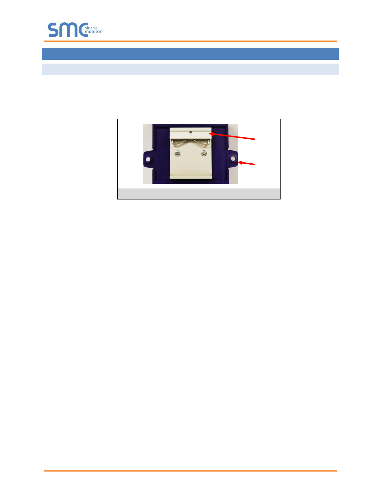
4.1 Mounting
The following mounting options are available:
• Product comes with tabs for wall or surface mount. These can be snapped off if not required.
• DIN rail mounting bracket - included in the accessory kit or ordered separately (part # FS-8915-
35-QS).
WARNING: Install only as instructed, failure to follow the installation guidelines or using screws
without the DIN rail mounting bracket could result in permanent damage to the product. If the
FieldServer is removed from the DIN rail, use the original screws to reattach. Only screws
supplied by SMC should be used in the holes found on the back of the unit when attaching the
optional DIN Rail bracket. USE OF ANY OTHER SCREWS MAY DAMAGE THE UNIT.
Figure 1: DIN Rail
Tab
Din Rail
QuickServer Start-Up Guide
Page 9 of 60
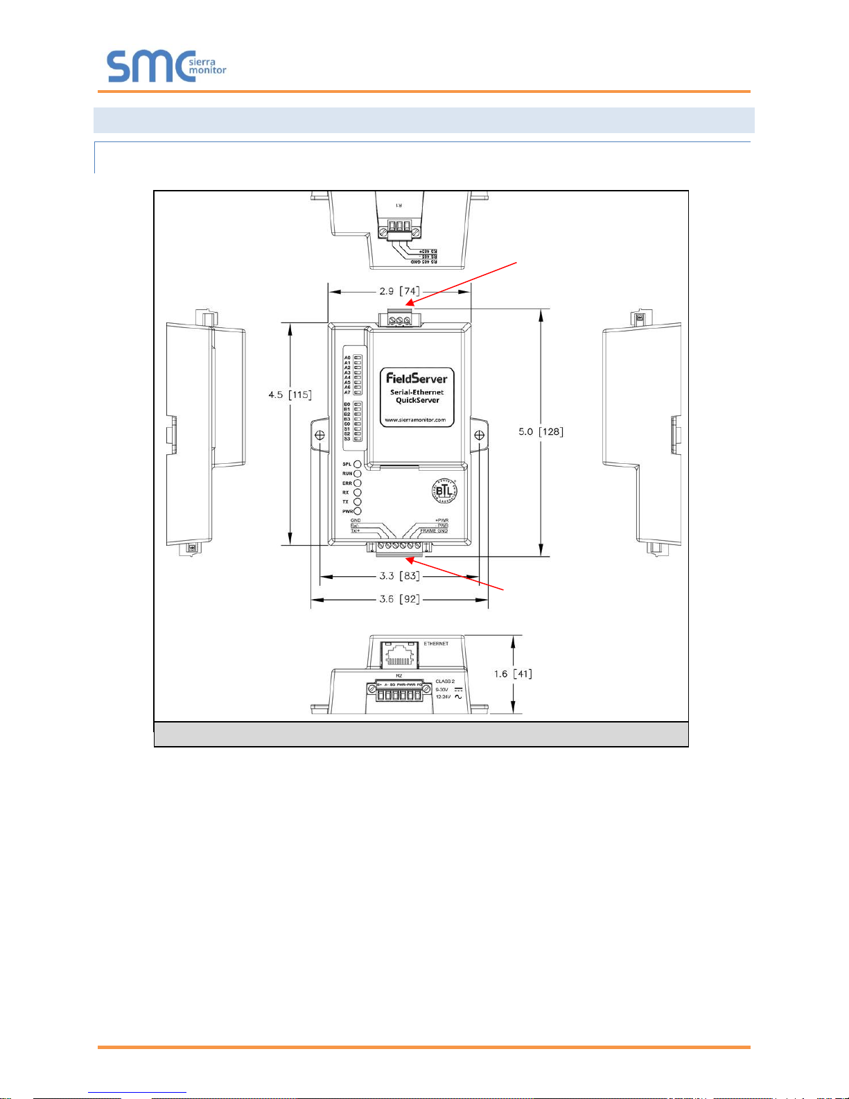
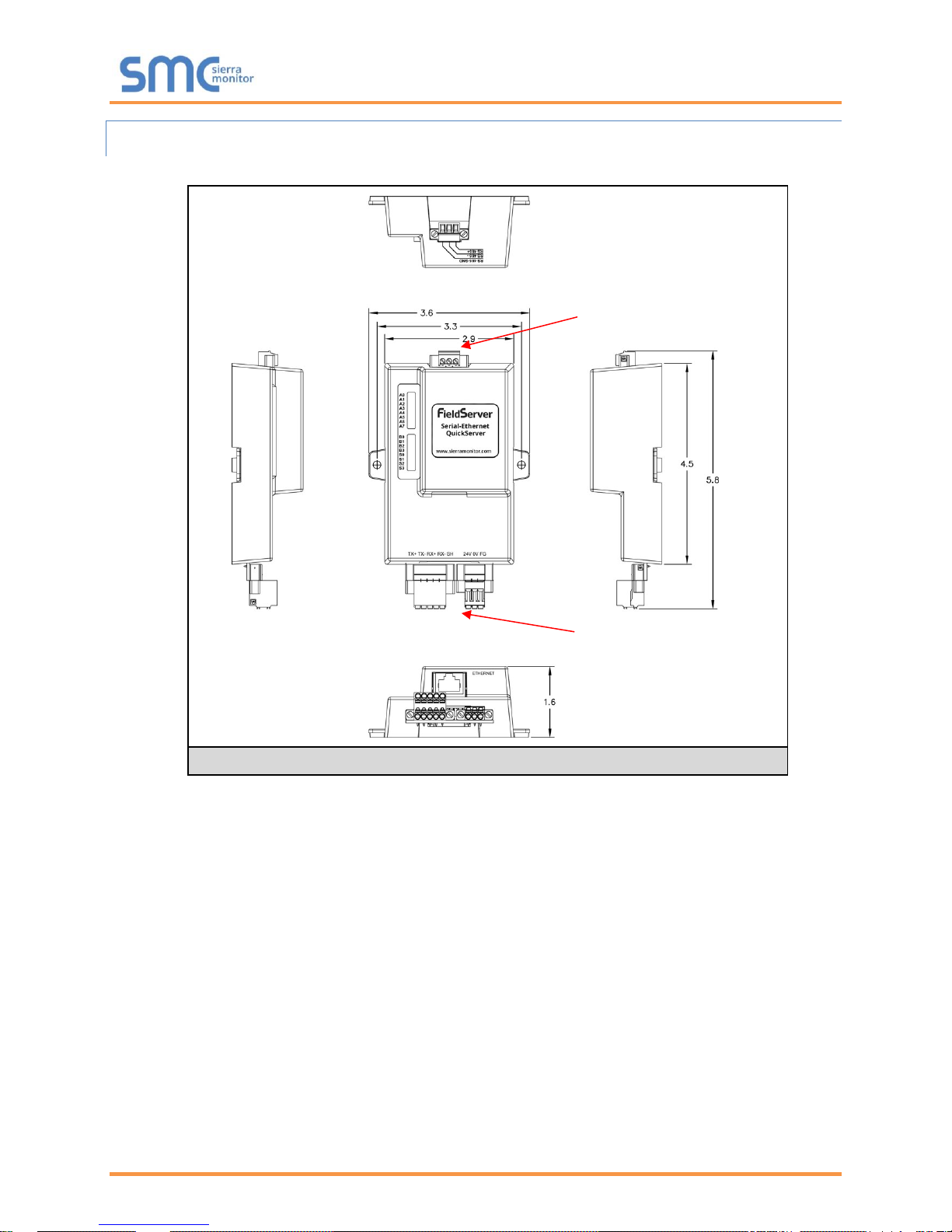
4.2 Dimensions
4.2.1 Dimension Drawing FS-QS-1X10-XXXX
R1 Port
R2 Port
Figure 2: FS-QS-1X10-XXXX
QuickServer Start-Up Guide
Page 10 of 60
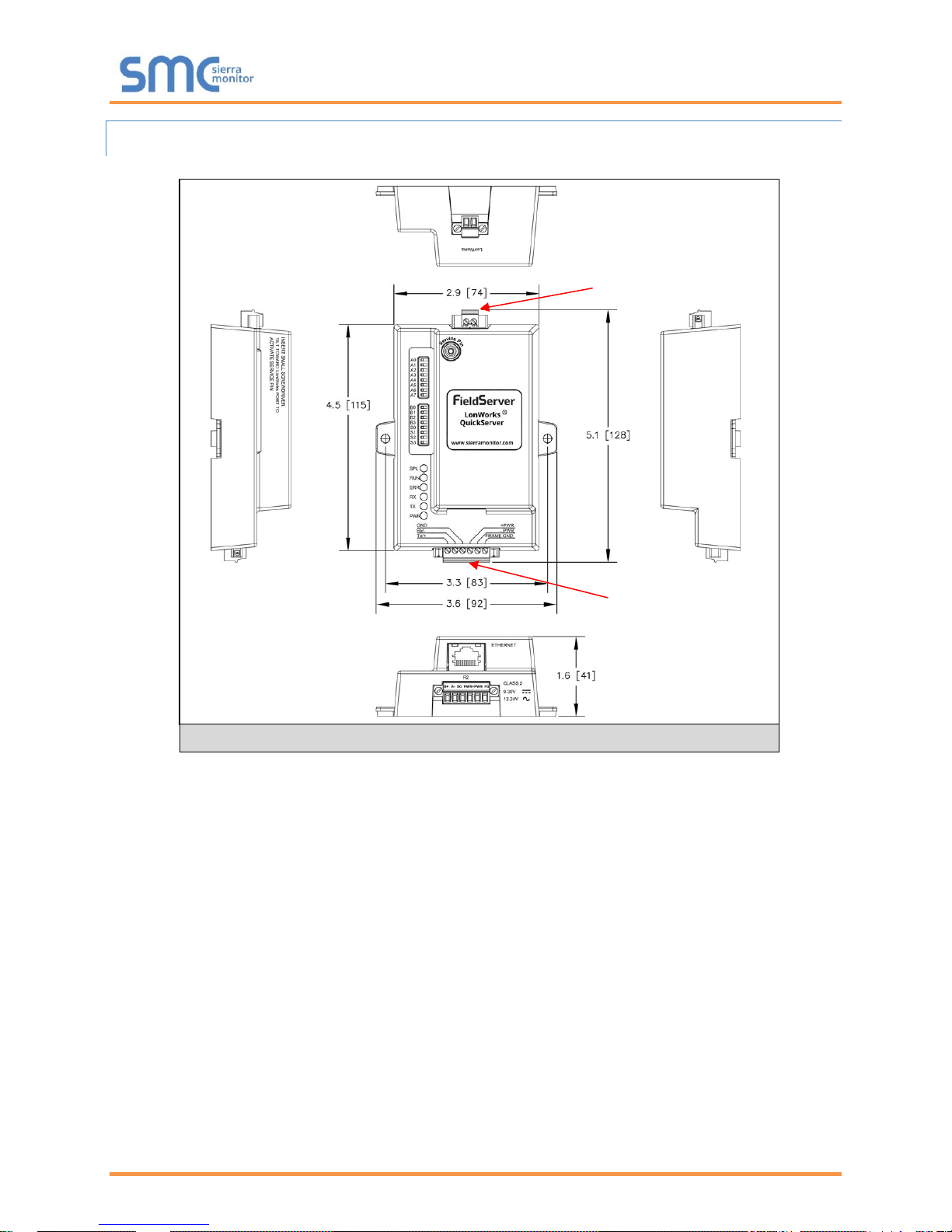
4.2.2 Dimension Drawing FS-QS-1XX1-XXXX
LonWorks Port
R2 Port
Figure 3: FS-QS-1XX1-XXXX
QuickServer Start-Up Guide
Page 11 of 60
4.2.3 Dimension Drawing FS-QS-123X Models with RS-422
R1 Port
R2 Port
Figure 4: FS-QS-123X models with RS-422

QuickServer Start-Up Guide
Page 12 of 60
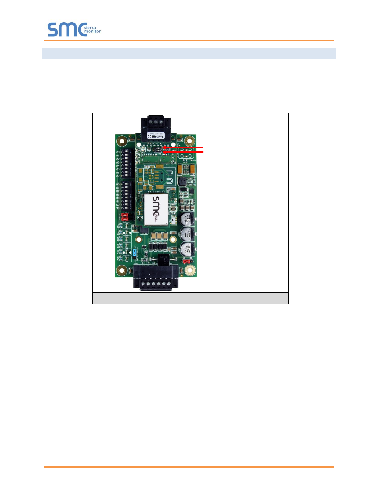
4.3 R2 Port Jumper Settings
Gently remove the QuickServer enclosure to access the jumpers on the unit.
4.3.1 RS-485 Port
NOTE: The following Sections only apply to QuickServer models: FS-QS-1010, FS-QS-1011,
FS-QS-1210 and FS-QS-1211.
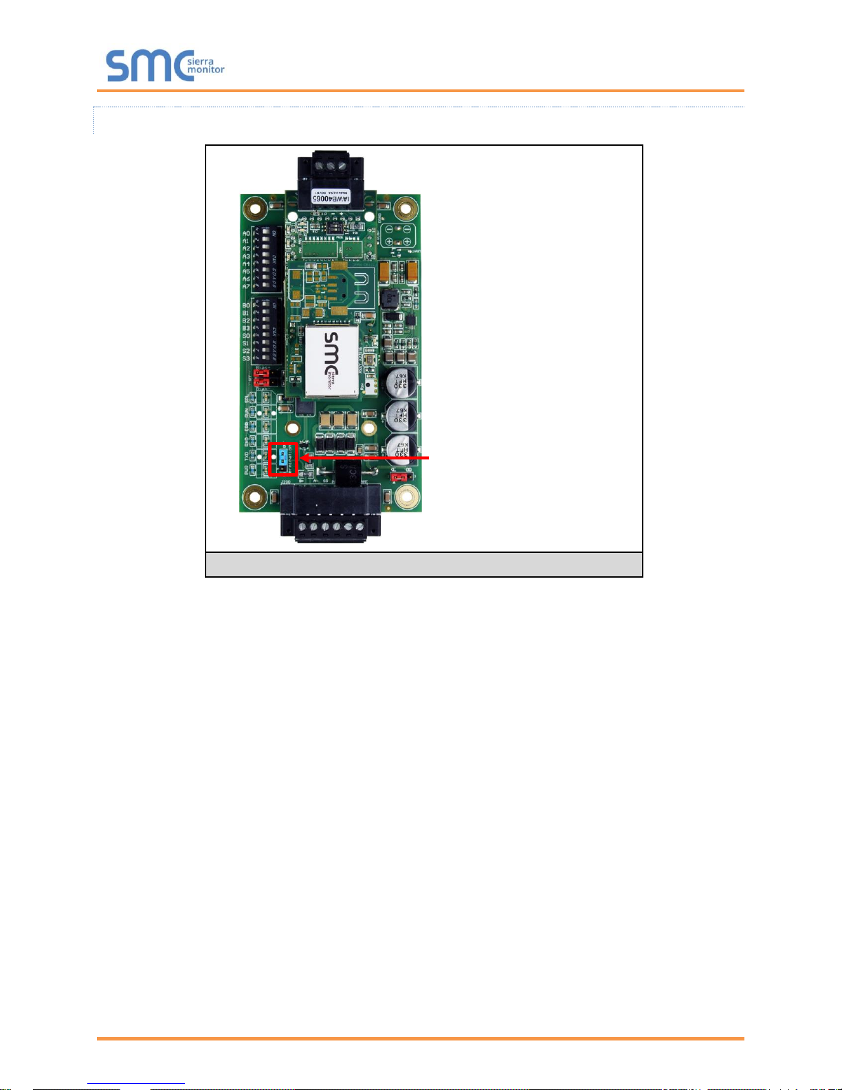
4.3.1.1 Bias Resistors
The QuickServer bias resistors are used to keep the RS-485 bus to a known state, when there is no
transmission on the line (bus is idling), to help prevent false bits of data from being detected. The bias
resistors typically pull one line high and the other low - far away from the decision point of the logic.
In the RS-485 carrier, the bias resistor is 510 ohms which is in line with the BACnet spec. It should only
be enabled at one point on the bus (on the field port were there are very weak bias resistors of 100k).
Since there are no jumpers, many FieldServers can be put on network without running into the bias
resistor limit which is < 500 ohms.
NOTE: See www.ni.com/support/serial/resinfo.htm for additional pictures and notes.
Bias Resistor Jumper
Figure 5: Bias Resistor Jumper
QuickServer Start-Up Guide
Page 13 of 60
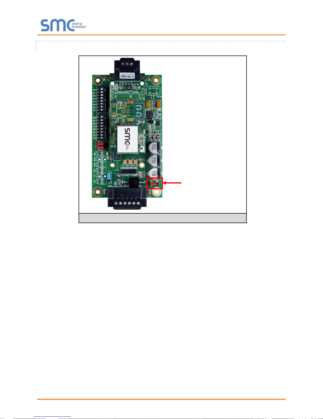
4.3.1.2 Termination Resistor
Termination resistors are also used to reduce noise. These pull the two lines of an idle bus together.
However, they would override the effect of any bias resistors, if connected.
Termination Resistor
Jumper
Figure 6: Termination Resistor Jumper
QuickServer Start-Up Guide
Page 14 of 60
4.3.1.3 Power Jumper Settings
The QuickServer Carrier Board power jumper is set to position A by default, but can be changed to
position B for other power supply requirements.
Position A: The Carrier makes use of a full-wave rectifying bridge. Can be used for 12-24VAC input or
9 – 30VDC input. At 9VDC this becomes marginal.
Position B: The Carrier makes use of a half-wave rectifying bridge. Best position for grounded AC
transformers and for using DC voltage down to 9VDC.
Power Jumper Switch
in position “A”
Figure 7: Power Jumper Switch
QuickServer Start-Up Guide
Page 15 of 60
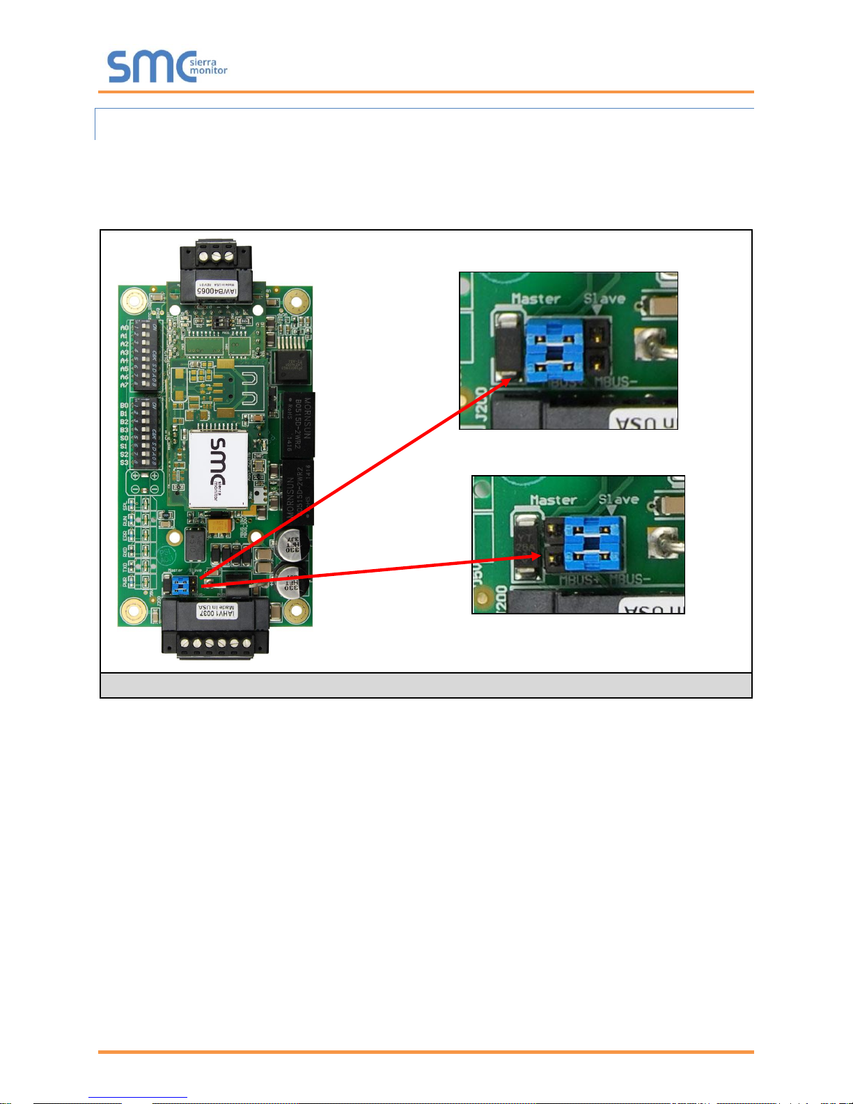
4.3.2 M-Bus Port: Master/Slave Jumper
NOTE: The following only applies to models: FS-QS-1A50, FS-QS-1A51, FS-QS-1B51, FS-QS-1B51,
FS-QS-1C51 and FS-QS-1C51.
The Master/Slave jumper is used to set the M-Bus hardware as a Master or Slave device (indicated by
the labels on the board).
Figure 8: Setting Master/Slave Jumper
QuickServer Start-Up Guide
Page 16 of 60
4.4 R1 Port Small DIP Switches
Gently remove the QuickServer enclosure to access the small DIP switches for the R1 Port.
4.4.1 RS-485 Port
NOTE: The following Sections only apply to QuickServer models FS-QS-1XX0 or all
non-LonWorks models.
• If more than one RS-485 device is connected to the network, then the field bias resistor switch
needs to be enabled to ensure proper communication. See Figure 9 for the orientation of
switch positions referenced below.
o The default factory setting is OFF (switch position = right side)
o To enable biasing, turn the bias switch ON (switch position = left side)
NOTE: Biasing only needs to be enabled on one device. The QuickServer has 510 ohm resistors
that are used to set the biasing.
• If the FieldServer is the last device on the trunk, then the end of line (EOL) termination switch
needs to be enabled. See Figure 9 for the orientation of switch positions referenced below.
o The default factory setting is OFF (switch position = right side)
o To enable the EOL termination, turn the EOL switch ON (switch position = left side)
Figure 9: Bias Resistor DIP Switches & EOL
Bias Resistor Switch
End of Line Switch
QuickServer Start-Up Guide
Page 17 of 60
5 INSTALLING THE QUICKSERVER
5.1 RS-485
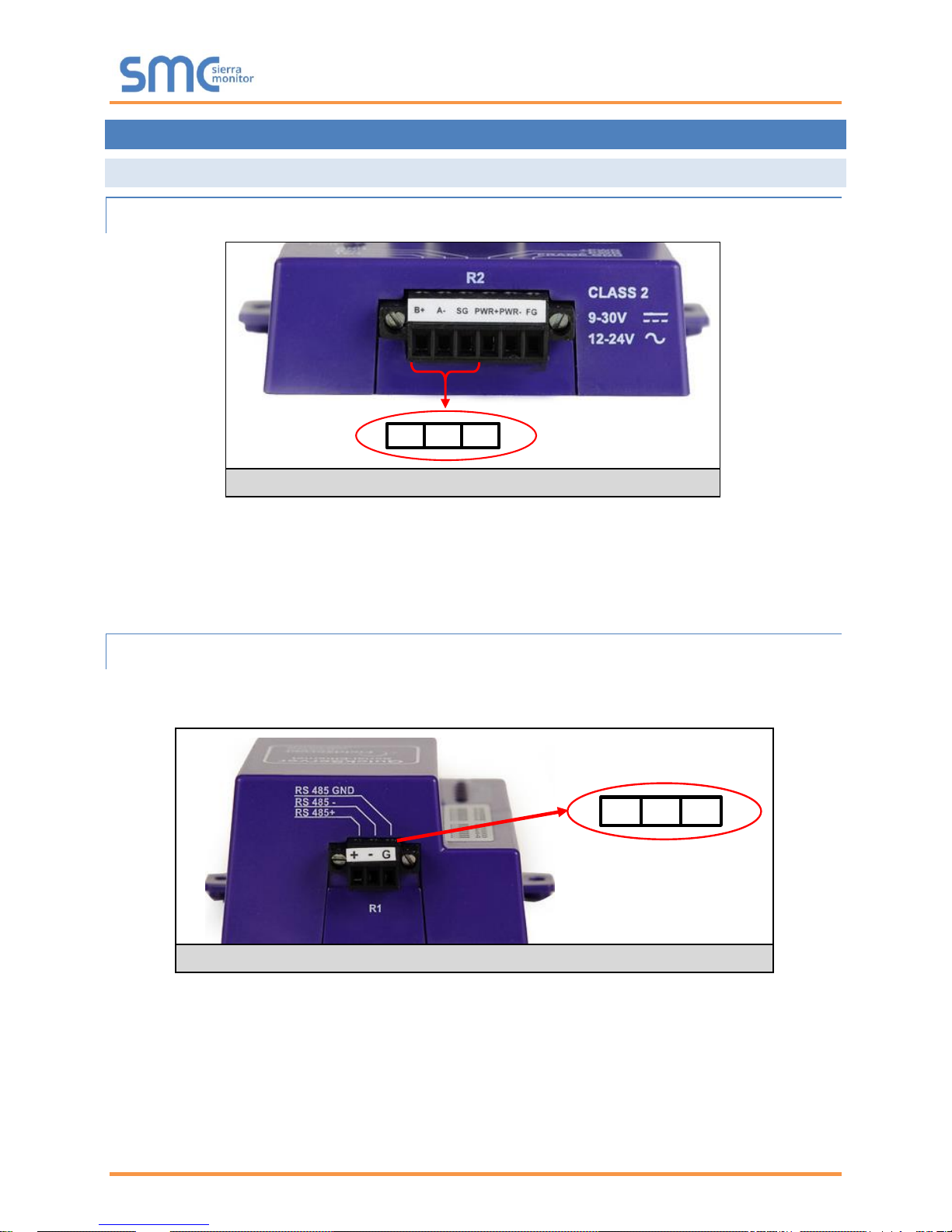
5.1.1 RS-485 Connection R2 Port
Connect to the 3 pins on the left-hand-side of the 6-pin connector as shown.
The following Baud Rates are supported on the R2 Port:
4800, 9600, 19200, 38400, 57600, 115200
For connection details to RS-232 or RS-422, refer to Appendix A.1.
5.1.2 RS-485 Connection R1 Port
NOTE: The following only applies to non-LonWorks QuickServers with an RS-435 R1 port.
Connect to the 3-pin connector as shown.
The following Baud Rates are supported on the R1 Port:
110, 300, 600, 1200, 2400, 4800, 9600, 19200, 20833, 28800, 38400, 57600, 76800, 115200
Figure 10: RS-485 R2 Connection Port
Figure 11: RS-485 R1 Connection Port
+ -
GND
B+ A- SG
QuickServer Start-Up Guide
Page 18 of 60
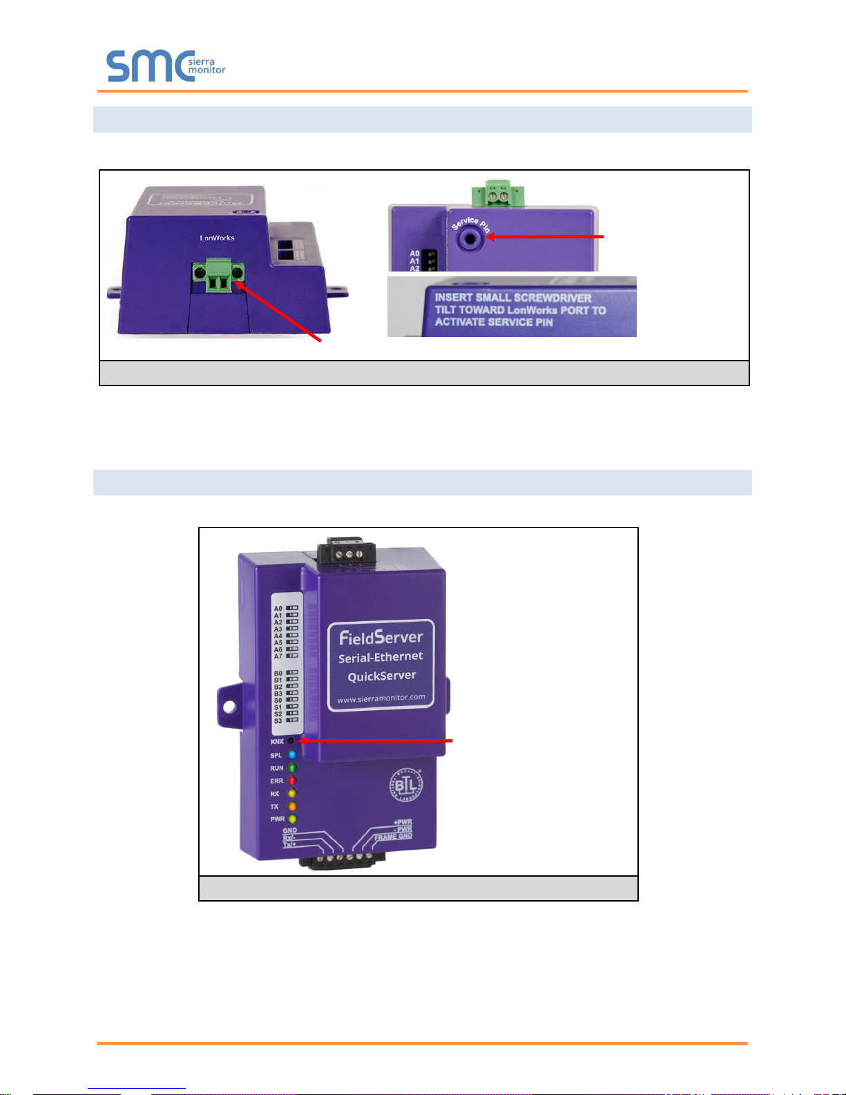
LonWorks Service Pin
5.2 QuickServer LonWorks (FS-QS-1XX1-XXXX)
Connect the QuickServer to the LonWorks terminal using a twisted pair non-shielded cable.
To commission the QuickServer LonWorks port, insert a small screwdriver in the commissioning hole on
the face of the QuickServer’s enclosure to access the Service Pin. See the instructions on the
QuickServer as to which way to toggle the screwdriver during commissioning.
5.3 QuickServer KNX (FS-QS-124X-XXXX)
Connect the QuickServer to the KNX bus using the standard KNX twisted pair cable.
To commission the QuickServer as a KNX device in ETS Software, insert a small pin into the KNX
commissioning hole on the face of the QuickServer to access the button.
LonWorks Terminal
Figure 13: KNX Commissioning
Figure 12: LonWorks Commissioning and Port
KNX Programming Button

QuickServer Start-Up Guide
Page 19 of 60
5.4 RS-232 Connection R2 Port (only available on FS-QS-122X Models)
Refer to Appendix A2 for further hardware connection options.
The following Baud Rates are supported on the R2 Port:
4800, 9600, 19200, 38400, 57600, 115200
Figure 14: RS-232 R2 Connection Port
TX RX SG

QuickServer Start-Up Guide
Page 20 of 60
6 OPERATION
6.1 Power Up the Device
Apply power to the device. Ensure that the power supply used complies with the specifications provided.
Ensure that the cable is grounded using the “Frame GND” terminal. The QuickServer is factory set for 930V DC or 12-24V AC.
6.2 Connect the PC to the QuickServer Over the Ethernet Port
• Connect an Ethernet cable between the PC and QuickServer or connect the QuickServer and the
PC to the switch using a straight CAT5 cable.
• The Default IP Address of the QuickServer is 192.168.2.101, Subnet Mask is 255.255.255.0.
Ethernet Port
Figure 15: Connecting Power
Figure 16: Ethernet Port
PWR+ PWR- FG

QuickServer Start-Up Guide
Page 21 of 60
6.3 Connecting to the QuickServer
6.3.1 Using the FieldServer Toolbox to Discover and Connect to the QuickServer
• Install the Toolbox application from the USB drive or download it from the Sierra Monitor website.
• Use the FS Toolbox application to find the QuickServer, and launch the FS-GUI.
NOTE: If the connect button is greyed out, the QuickServer’s IP Address must be set to be on the
same network as the PC. (Section 6.4)
6.3.2 Accessing SMC Cloud
The FieldPoP™ button (see Figure 17) allows users to connect to the SMC Cloud, Sierra
Monitor’s device cloud solution for IIoT. The SMC Cloud enables secure remote connection to field
devices through a FieldServer and its local applications for configuration, management, maintenance. For
more information about the SMC Cloud, refer to the SMC Cloud Start-up Guide.
Figure 17: FS-GUI Landing Page

QuickServer Start-Up Guide
Page 22 of 60
6.4 Set IP Address of the QuickServer
6.4.1 Using the FS Toolbox Application to Set the IP Address
• From the FS Toolbox main page, click on the setup icon (gear icon).
• Select Network Settings.
• Modify the IP Address (N1 IP Address field) of the QuickServer Ethernet port.
o The following fields may also be changed as needed: Netmask (N1 Netmask field), DHCP
Client State (N1 DHCP Client State field), IP Gateway (Default Gateway field) and DNS 1 & 2
(Domain Name Server fields)
NOTE: If the QuickServer is connected to a router, the IP Gateway of the QuickServer should be
set to the IP Address of that router.
NOTE: Do not change the DHCP Server State (N1 DHCP Server State field).
NOTE: If DNS settings are unknown, set DNS1 to “8.8.8.8” and DNS2 to “8.8.4.4”.
• Click “Update IP Settings”, then click on the “Change and Restart” to restart the Gateway and
activate the new IP Address.
NOTE: If the FS-GUI was open in a browser, the browser will need to be pointed to the new IP
Address of the QuickServer before the FS-GUI will be accessible again.

QuickServer Start-Up Guide
Page 23 of 60
6.4.2 Using the FS-GUI to Set the IP Address
• From the FS-GUI main home page, click on setup and then Network Settings to enter the Edit IP
Address Settings menu.
• Modify the IP Address (N1 IP Address field) of the QuickServer Ethernet port.
• If necessary, change the Netmask (N1 Netmask field).
• Type in a new Subnet Mask.
• If necessary, change the IP Gateway (Default Gateway field).
• Type in a new IP Gateway.
NOTE: If the FieldServer is connected to a router, the IP Gateway of the FieldServer should be set
to the same IP Address of the router.
• Click Update IP Settings, then click on the System Restart to restart the Gateway and activate the
new IP Address.
NOTE: If the FS-GUI was open in a browser, the browser will need to be pointed to the new IP
Address of the QuickServer before the FS-GUI will be accessible again.
Figure 18: FS-GUI Network Settings

QuickServer Start-Up Guide
Page 24 of 60
7 CONFIGURING THE QUICKSERVER
7.1 Retrieve the Sample Configuration File
The configuration of the QuickServer is provided to the QuickServer’s operating system via a commadelimited file called “CONFIG.CSV”.
If a custom configuration was ordered, the QuickServer will be programmed with the relevant device
registers in the Config.csv file for the initial start-up. If not, the product is shipped with a sample config.csv
that shows an example of the drivers ordered.
• In the main menu of the FS-GUI screen, go to “Setup”, then “File Transfer”, and finally “Retrieve”.
• Click on “config.csv”, and open or save the file.
7.2 Change the Configuration File to Meet the Application
Refer to the FieldServer Configuration Manual in conjunction with the Driver supplements for information
on configuring the QuickServer.
Figure 19: FS-GUI File Transfer

QuickServer Start-Up Guide
Page 25 of 60
7.3 Load the Updated Configuration File
7.3.1 Using the Toolbox Application to Load a Configuration File
• From the Toolbox main page, click on the setup icon (the gear picture).
• Select File Transfer.
• Browse and select the .csv file, open, then click “Update Config”.
• Once download is complete, click the Restart Button (or cycle power to the QuickServer) to put
the new file into operation.
NOTE: It is possible to do multiple downloads to the QuickServer before resetting it.

QuickServer Start-Up Guide
Page 26 of 60
7.3.2 Using the FS-GUI to Load a Configuration File
• In the main menu of the FS-GUI screen, click “Setup”, then “File Transfer” and finally “Update”.
• Browse and select the .csv file, open, then click “Submit”.
• Once download is complete, a message bar will appear confirming that the configuration was
updated successfully.
• Click the System Restart Button to put the new file into operation.
NOTE: It is possible to do multiple downloads to the QuickServer before resetting it.
Figure 20: FS-GUI Loading Files

QuickServer Start-Up Guide
Page 27 of 60
7.3.3 Retrieve the Configuation File for Modification or Backup
To get a copy of the configuration file for modifying or backing up a configuration on a local computer, do
the following:
• In the main menu of the FS-GUI screen, click “Setup”, then “File Transfer”.
• Click the “config.csv” link under the “Retrieve” heading in the middle section of the screen.
o The file will automatically download to the web browser’s default download location.
• Edit or store the file as desired.
NOTE: Before using any backup configuration file to reset the configuration settings, check that
the backup file is not an old version.
Figure 21: Retrieve Configuration File

QuickServer Start-Up Guide
Page 28 of 60
7.4 Test and Commission the QuickServer
• Connect the QuickServer to the third party device(s), and test the application.
• From the landing page of the FS-GUI click on “View” in the navigation tree, then “Connections” to
see the number of messages on each protocol.
Figure 22: FS-GUI Connections Page

QuickServer Start-Up Guide
Page 29 of 60
Appendix A Useful Features
Appendix A.1. RS-422 Connection R2 Port
NOTE: The following only applies to models: FS-QS-1230 and FS-QS-1231.
RS-422 is a full duplex multi-drop multi-master differential bus. It can be wired to conform to a RS-485
network when less wiring/cabling is used (due to being less expensive to install), but then it becomes a
half-duplex multi-drop multi-master differential bus. RS-422 is used for dedicated peer to peer high speed
communication when low bus latency is required (very few devices on the bus). Its usage is very specific
to client installations/requirements.
NOTE:
• The RS-232 looks similar to the RS-485 but does not have the blue jumper. The blue jumper is
used to enable the termination resistor for the RX signals (120 ohms), while the red jumpers are
used to enable the bias resistors for RX signals (510 ohms). In the case of Rockwell/Tetrapak, all
jumpers are always required to be in default position (not enabled). For other clients, the bias
resistors should always be in the “on” state.
• The part number on the back of the box will identify the port.
Figure 23: RS-422 Unit

QuickServer Start-Up Guide
Page 30 of 60
Appendix A.1.1. Connection and Operation via the RS-422 Port
RS-422 Connector
Pin 1-2: TX +/- (Differential TX outputs: All + signals must be connected to each other, and same applies
to - signals; no +/- signals may be crossed)
Pin 3-4: RX +/- (Differential RX inputs: All + signals must be connected to each other, and same applies
to - signals, no +/- signals may be crossed)
Pin 5: SHD (Shield connection, must be connected on at least one side of the bus, but not necessarily
on both sides)
POWER Connector
Please note that AC voltage is not supported on the RS-422 carrier, and that DC voltage range is
~20VDC to ~28VDC.
Pin 1: +24V (DC power requires this pin be used for the positive voltage)
Pin 2: 0V (DC power requires this pin is used for ground / return voltage)
Pin 3: FG (this pin needs to be connected to EARTH or noise free reference point - CHASSIS)
5-pin RS-422
Connector
3-pin Power
Connector
Figure 24: RS-422 Connectors

QuickServer Start-Up Guide
Page 31 of 60
Appendix A.2. KNX Connection R2 Port
NOTE: The following only applies to models: FS-QS-1240 and FS-QS-1241.
The KNX QuickServer is used to transfer data to and from devices using KNX protocol. The KNX driver
enables data access from KNX networks to other FieldServer protocols. Most KNX data-point types are
supported, allowing communication to almost any kind of KNX device in an installation, such as
temperature sensors, shutters, light switches, actuators, alarms, etc. This allows BMS systems to access
a KNX network using direct read and write or with KNX configured groups. This setup does not require
the use of ETS4 to configure the QuickServer KNX gateway. The KNX protocol is a connectionless
protocol and therefore supports multiple clients and multiple servers. The QuickServer is intended to act
as a Passive Client on the KNX bus and makes information available to other protocols.
The KNX Connector consist of a KNX + and KNX- terminal. Each terminal corresponds to the red KNX+
and gray KNX- bus connections on a KNX bus.
The following Baud Rates are supported on the R2 Port:
4800, 9600, 19200, 38400, 57600, 115200
KNX+ KNX- No Connection
Figure 25: KNX Unit

QuickServer Start-Up Guide
Page 32 of 60
Appendix A.3. M-Bus Connection R2 Port
NOTE: The following only applies to models: FS-QS-1A50, FS-QS-1A51, FS-QS-1B50, FS-QS-1B51,
FS-QS-1C50 and FS-QS-1C51.
The M-Bus driver allows the FieldServer to transfer data to and from devices using M-Bus protocol. The
Fieldbus connection is included with the FieldServer. The M-Bus QuickServer Gateway is configurable to
act as both a Master and a Slave M-Bus device.
The M-Bus Connector consist of a + and – terminal. Most M-Bus Devices are not polarity sensitive,
although the polarity of the M-Bus Connector is indicated on the device diagram, should it be a
requirement. The M-Bus devices to communicate with the FieldServer must be configured according to
the manufacturer’s instructions (for example primary address and readout data).
The following baud rates are supported on the R2 Port:
300, 600, 1200, 2400, 4800, 9600, 19200, 38400
Figure 26: M-Bus R2 Port

QuickServer Start-Up Guide
Page 33 of 60
Appendix A.4. SSL/TLS for Secure Connection
SSL/TLS (Secure Sockets Layer/Transport Layer Security) is a security technology for establishing an
encrypted connection between a server and a client. This allows the secure transfer of data across
untrusted networks.
These functions are supported on the following:
FS-QS-1010 or FS-QS-1210 with a serial number starting with 14 or later (indicating the year it shipped).
FS-QS-1011 or FS-QS-1211 with a serial number starting with 15 or later (indicating the year it shipped).
Minimum BIOS requirement: 2.6.1
Appendix A.4.1. Configuring FieldServer as a SSL/TLS Server
The following example sets the FieldServer to accept a secure Modbus/TCP connection on port 1502.
Appendix A.4.1.1. Simple Secure Server Configuration
Add TLS_Port parameter in the connections section of the configuration file and set to a port number
between 1 – 65535.
Connections
Adapter , Protocol , TLS_Port
N1 , Modbus/TCP , 1502
This configuration sets the FieldServer to accept any incoming connection but will not request a client’s
certificate for verification. This means that the FieldServer end point communication will be encrypted but
not authenticated.
The FieldServer will send an embedded self-signed certificate if one is requested by a connecting client.
NOTE: If a remote client requires a certificate, then request the smc_cert.pem certificate from
Sierra Monitor Technical Support and update the remote client’s authority as per vendor
instructions.

QuickServer Start-Up Guide
Page 34 of 60
Appendix A.4.1.2. Limiting Client Access
In addition to TLS_Port parameter also add Validate_Client_Cert in the connections section of the
configuration file and set it to “Yes”.
Connections
Adapter , Protocol , TLS_Port , Validate_Client_Cert
N1 , Modbus/TCP , 1502 , Yes
The configuration above sets the FieldServer to request and verify a client’s certificate against its internal
authority file before accepting connection. By default, this means the FieldServer will only accept
connections from other FieldServers.
In order to load an authority file so that the FieldServer will accept connections from a chosen list of
remote clients, configure the FieldServer with the following connection settings:
Connections
Adapter , Protocol , TLS_Port , Validate_Client_Cert , Cert_Authority_File
N1 , Modbus/TCP , 1502 , Yes , my_authorized_clients.pem
This configuration has the FieldServer accept connections from clients who have the correct certificate.
The authority file is a collection of client certificates in PEM format. This file can be edited using any text
file editor.
NOTE: Cert_Authority_File is useful only if Validate_Client_Cert is set to ‘Yes’.
Appendix A.4.1.3. To Upload the Authority File to the FieldServer
• Enter the IP address of the FieldServer into a web browser.
• Choose the ‘Setup’ option in the Navigation Tree and Select ‘File Transfer’.
• Choose the ‘General’ tab.
• Click on the ‘Browse’ button and select the PEM file you want to upload.
• Click on ‘Submit’.
• When the message, “The file was uploaded successfully” appears, click on the ‘System
Restart’ button.

QuickServer Start-Up Guide
Page 35 of 60
Appendix A.4.1.4. Certificate Validation Options
If connections must be limited to only a particular domain (vendor devices), include Check_Remote_Host
to specify the domain/host name.
Connections
Adapter , Protocol , TLS_Port , Validate_Client_Cert , Cert_Authority_File , Check_Remote_Host
N1 , Modbus/TCP , 1502 , Yes , my_authorized_clients.pem , SMC
The configuration above tells the FieldServer to only accept connections that have the correct certification
and is coming from the specified host.
The Check_Remote_Host value is synonymously known as common name, host name or domain etc.
The common name can be obtained by the following methods:
• Ask the certificate issuer for the host name.
• Use online tools to decode the certificate (for example: https://www.sslshopper.com/certificate-
decoder.html).
• If the program openssl is installed on the local PC, then run the following command to get the
common name: openssl x509 -in certificate.pem -text -noout
Appendix A.4.1.5. Set up Server Certificate
Make sure the certificate is in PEM format. Otherwise, convert it to PEM format (reference the link below).
support.ssl.com/Knowledgebase/Article
Configure the FieldServer to use a custom certificate as shown below:
Connections
Adapter , Protocol , TLS_Port , Server_Cert_File
N1 , Modbus/TCP , 1502 , my_server_cert.pem

QuickServer Start-Up Guide
Page 36 of 60
Appendix A.4.2. Configuring FieldServer as SSL/TLS Client
The following Node configurations set the FieldServer to open a secure Modbus/TCP connection to
Server at IP Address 10.11.12.13 on port 1502.
Appendix A.4.2.1. Simple Secure Client Configuration
Add Remote_Node_TLS_Port parameter in the nodes section of the configuration file and set to a port
number between 1 – 65535.
Nodes
Node_Name , Node_ID , Protocol , Adapter , IP_Address , Remote_Node_TLS_Port
PLC_11 , 11 , Modbus/TCP , N1 , 10.11.12.13 , 1502
The above configuration sets the FieldServer to connect to a remote server but does not request a
server’s certificate for verification. This means that the FieldServer end point communication will be
encrypted but not authenticated.
If requested by a remote server, the FieldServer will send an embedded self-signed certificate.
Appendix A.4.2.2. Limit Server Access
Add the Validate_Server_Cert parameter to the client node section of the configuration.
……. , Remote_Node_TLS_Port , Validate_Server_Cert
…….. , 1502 , Yes
The above configuration sets the FieldServer to request and verify the server’s certificate against its own
internal authority file before finalizing the connection. By default, this means the FieldServer will only
establish connections to other FieldServers.
……. , Remote_Node_TLS_Port , Validate_Server_Cert , Cert_Authority_File
…….. , 1502 , Yes , my_authorized_servers.pem
The above configuration sets the FieldServer to use a specified PEM file to allow custom server
connections.
The authority file is a collection of server certificates in PEM format. This file can be edited using any text
file editor (such as notepad). When the file has all required certificates, paste it into the PEM formatted
server certificate. Now the FieldServer will connect to a server if it can find the server’s certificate in the
authority file.
NOTE: Cert_Authority_File is useful only if Validate_Client_Cert is set to ‘Yes’.
To upload the Certificate to the FieldServer follow the directions for the authority file in Appendix A.4.1.3.
Appendix A.4.2.3. Certificate Validation Options
Use the Check_Remote_Host element as described in Appendix A.4.1.4.
Appendix A.4.2.4. Set up Client Certificate
Make sure the certificate is in PEM format. Otherwise, convert it to PEM format (reference the link below).
support.ssl.com/Knowledgebase/Article
Configure the FieldServer to use a custom certificate as shown below:
……… , Client_Cert_File
……… , my_client_cert.pem

QuickServer Start-Up Guide
Page 37 of 60
Appendix B Vendor Information – M-Bus Data Profiles
NOTE: All points are Float Data Type. The first Modbus register contains the least significant
word.
Appendix B.1. Aquametro Calec ST
Mappings to BACnet and Modbus
Point Name
BACnet
Modbus
Vol_Flo_1
AI 01
30001-30002
Temp_Flo_1
AI 02
30003-30004
Temp_Ret_1
AI 03
30005-30006
Temp_Diff_1
AI 04
30007-30008
Power_W_1
AI 05
30009-30010
Energy_Wh_1
AI 06
30011-30012
Energy_Wh_2
AI 07
30013-30014
Volume_1
AI 08
30015-30016
Volume_2
AI 09
30017-30018
Time_1
AI 10
30019-30020
Time_2
AI 11
30021-30022
Mass_1
AI 12
30023-30024
Time_P_1
AI 13
30025-30026
Time_P_2
AI 14
30027-30028
Time_P_3
AI 15
30029-30030
Unknown_1
AI 16
30031-30032
Unknown_2
AI 17
30033-30034
Unknown_3
AI 18
30035-30036
Unknown_4
AI 19
30037-30038
Unknown_5
AI 20
30039-30040
Unknown_6
AI 21
30041-30042
Unknown_7
AI 22
30043-30044
Unknown_8
AI 23
30045-30046
Unknown_9
AI 24
30047-30048
Appendix B.2. Comet XRM-50 Mappings to
BACnet and Modbus
Point Name
BACnet
Modbus
MBUS_Meter_$node_id_Alarms
AI 01
30001-30002
Volume
AI 02
30003-30004
Time_stamp
AI 03
30005-30006
Error_Flags
AI 04
30007-30008
M_BUS_STATE
AI 05
30009-30010
Appendix B.3. Elvaco CMa20 Mappings to
BACnet and Modbus
Point Name
BACnet
Modbus
MBUS_Meter_$node_id_Alarms
AI 01
30001-30002
Temp_Inst
AI 02
30003-30004
Temp_Min
AI 03
30005-30006
Temp_Max
AI 04
30007-30008
Temp_Avg
AI 05
30009-30010
RH_Ins
AI 06
30011-30012
RH_Min
AI 07
30013-30014
RH_Max
AI 08
30015-30016
RH_Avg
AI 09
30017-30018
Appendix B.4. EMU 3PH Power 3-85
Mappings to BACnet and Modbus
Point Name
BACnet
Modbus
MBUS_Meter_$node_id_Alarms
AI 01
30001-30002
Energy_WH_1
AI 02
30003-30004
Energy_WH_2
AI 03
30005-30006
Energy_WH_3
AI 04
30007-30008
Voltage_1
AI 05
30009-30010
Voltage_2
AI 06
30011-30012
Voltage_3
AI 07
30013-30014
Current_1
AI 08
30015-30016
Current_2
AI 09
30017-30018
Current_3
AI 10
30019-30020
Appendix B.5. Kamstrup 601 Mappings to
BACnet and Modbus
Point Name
BACnet
Modbus
Energy_T_WH_1
AI 01
30001-30002
Energy_T_WH_2
AI 02
30003-30004
Energy_T_WH_3
AI 03
30005-30006
Energy_T_WH_4
AI 04
30007-30008
Energy_T_WH_5
AI 05
30009-30010
Energy_T_WH_6
AI 06
30011-30012
Energy_T_WH_7
AI 07
30013-30014
Energy_T_WH_8
AI 08
30015-30016
Energy_T_WH_9
AI 09
30017-30018
Energy_T_WH_10
AI 10
30019-30020
Temp_Flow_1
AI 11
30021-30022
Temp_Flow_2
AI 12
30023-30024
Temp_Flow_3
AI 13
30025-30026
Temp_Ret_1
AI 14
30027-30028
Temp_Ret_2
AI 15
30029-30030
Temp_Ret_3
AI 16
30031-30032
Temp_Dif_1
AI 17
30033-30034
Temp_Dif_2
AI 18
30035-30036
Temp_Dif_3
AI 19
30037-30038
Time_Hrs_1
AI 20
30039-30040
Time_Hrs_2
AI 21
30041-30042
Time_Hrs_3
AI 22
30043-30044
Power_W_1
AI 23
30045-30046
Power_W_2
AI 24
30047-30048
Power_W_3
AI 25
30049-30050
Power_W_4
AI 26
30051-30052
Power_W_5
AI 27
30053-30054
Power_W_6
AI 28
30055-30056
Power_W_7
AI 29
30057-30058
Power_W_8
AI 30
30059-30060
Power_W_9
AI 31
30061-30062
Vol_Flo_L_H_1
AI 32
30063-30064
Vol_Flo_L_H_2
AI 33
30065-30066
Vol_Flo_L_H_3
AI 34
30067-30068
Vol_Flo_L_H_4
AI 35
30069-30070
Vol_Flo_L_H_5
AI 36
30071-30072
Vol_Flo_L_H_6
AI 37
30073-30074
Vol_Flo_L_H_7
AI 38
30075-30076
Vol_Flo_L_H_8
AI 39
30077-30078

QuickServer Start-Up Guide
Page 38 of 60
Vol_Flo_L_H_9
AI 40
30079-30080
Volume_1
AI 41
30081-30082
Volume_2
AI 42
30083-30084
Volume_3
AI 43
30085-30086
Volume_4
AI 44
30087-30088
Volume_5
AI 45
30089-30090
Volume_6
AI 46
30091-30092
Volume_7
AI 47
30093-30094
Volume_8
AI 48
30095-30096
Volume_9
AI 49
30097-30098
Volume_10
AI 50
30099-30100
Time_Point_1
AI 51
30101-30102
Time_Point_2
AI 52
30103-30104
Time_Point_3
AI 53
30105-30106
Time_Point_4
AI 54
30107-30108
Time_Point_5
AI 55
30109-30110
Time_Point_6
AI 56
30111-30112
ID_Num_1
AI 57
30113-30114
ID_Num_2
AI 58
30115-30116
ID_Num_3
AI 59
30117-30118
Appendix B.6. Kamstrup 602 Mappings to
BACnet and Modbus
Point Name
BACnet
Modbus
Energy_T_WH_1
AI 01
30001-30002
Energy_T_WH_2
AI 02
30003-30004
Energy_T_WH_3
AI 03
30005-30006
Energy_T_WH_4
AI 04
30007-30008
Energy_T_WH_5
AI 05
30009-30010
Energy_T_WH_6
AI 06
30011-30012
Energy_T_WH_7
AI 07
30013-30014
Energy_T_WH_8
AI 08
30015-30016
Energy_T_WH_9
AI 09
30017-30018
Energy_T_WH_10
AI 10
30019-30020
Temp_Flow_1
AI 11
30021-30022
Temp_Flow_2
AI 12
30023-30024
Temp_Flow_3
AI 13
30025-30026
Temp_Ret_1
AI 14
30027-30028
Temp_Ret_2
AI 15
30029-30030
Temp_Ret_3
AI 16
30031-30032
Temp_Dif_1
AI 17
30033-30034
Temp_Dif_2
AI 18
30035-30036
Temp_Dif_3
AI 19
30037-30038
Temp_Dif_4
AI 20
30039-30040
Temp_Dif_5
AI 21
30041-30042
Temp_Dif_6
AI 22
30043-30044
Time_Hrs_1
AI 23
30045-30046
Time_Hrs_2
AI 24
30047-30048
Time_Hrs_3
AI 25
30049-30050
Power_W_1
AI 26
30051-30052
Power_W_2
AI 27
30053-30054
Power_W_3
AI 28
30055-30056
Power_W_4
AI 29
30057-30058
Power_W_5
AI 30
30059-30060
Power_W_6
AI 31
30061-30062
Power_W_7
AI 32
30063-30064
Power_W_8
AI 33
30065-30066
Power_W_9
AI 34
30067-30068
Power_W_10
AI 35
30069-30070
Vol_Flo_L_H_1
AI 36
30071-30072
Vol_Flo_L_H_2
AI 37
30073-30074
Vol_Flo_L_H_3
AI 38
30075-30076
Vol_Flo_L_H_4
AI 39
30077-30078
Vol_Flo_L_H_5
AI 40
30079-30080
Vol_Flo_L_H_6
AI 41
30081-30082
Vol_Flo_L_H_7
AI 42
30083-30084
Vol_Flo_L_H_8
AI 43
30085-30086
Vol_Flo_L_H_9
AI 44
30087-30088
Vol_Flo_L_H_10
AI 45
30089-30090
Volume_1
AI 46
30091-30092
Volume_2
AI 47
30093-30094
Volume_3
AI 48
30095-30096
Volume_4
AI 49
30097-30098
Volume_5
AI 50
30099-30100
Volume_6
AI 51
30101-30102
Volume_7
AI 52
30103-30104
Volume_8
AI 53
30105-30106
Volume_9
AI 54
30107-30108
Volume_10
AI 55
30109-30110
Time_Point_1
AI 56
30111-30112
Time_Point_2
AI 57
30113-30114
Time_Point_3
AI 58
30115-30116
Time_Point_4
AI 59
30117-30118
Time_Point_5
AI 60
30119-30120
Time_Point_6
AI 61
30121-30122
ID_Num_1
AI 62
30123-30124
ID_Num_2
AI 63
30125-30126
ID_Num_3
AI 64
30127-30128
Appendix B.7. Sontay Zenner Multidata
Mappings to BACnet and Modbus
Point Name
BACnet
Modbus
ID_1
AI 01
30001-30002
Energy_WH_1
AI 02
30003-30004
Volume_1
AI 03
30005-30006
Volume_2
AI 04
30007-30008
Error_Flags
AI 05
30009-30010
Energy_WH_2
AI 06
30011-30012
Volume_3
AI 07
30013-30014
Volume_4
AI 08
30015-30016
Volume_5
AI 09
30017-30018
Vol_Flow_1
AI 10
30019-30020
Power_W_1
AI 11
30021-30022
Temp_Flow
AI 12
30023-30024
Temp_Return
AI 13
30025-30026
Energy_WH_5
AI 14
30027-30028
Energy_WH_6
AI 15
30029-30030
Energy_WH_7
AI 16
30031-30032
Energy_WH_8
AI 17
30033-30034
Energy_WH_9
AI 18
30035-30036
Energy_WH_10
AI 19
30037-30038
Appendix B.8. Sontex SuperCal 531
Mappings to BACnet and Modbus
Point Name
BACnet
Modbus
Dur_Avg_S_1
AI 01
30001-30002
Dur_Avg_M_1
AI 02
30003-30004
Energy_T_WH_1
AI 03
30005-30006
Energy_T_WH_2
AI 04
30007-30008
Energy_T_WH_3
AI 05
30009-30010
Energy_T_WH_4
AI 06
30011-30012
Energy_T_WH_5
AI 07
30013-30014
Energy_T_WH_6
AI 08
30015-30016
Energy_T_WH_7
AI 09
30017-30018
Energy_T_WH_8
AI 10
30019-30020
Energy_T_WH_9
AI 11
30021-30022

QuickServer Start-Up Guide
Page 39 of 60
Energy_T_WH_10
AI 12
30023-30024
Temp_Flow_1
AI 13
30025-30026
Temp_Ret_1
AI 14
30027-30028
Time_Hrs_1
AI 15
30029-30030
Vol_Flo_L_S_1
AI 16
30031-30032
Error_Flags_1
AI 17
30033-30034
Medium_1
AI 18
30035-30036
Medium_2
AI 19
30037-30038
Volume_1
AI 20
30039-30040
Appendix B.9. Siemens WFH21 Mappings
to BACnet and Modbus
Point Name
BACnet
Modbus
Energy_T_WH_1
AI 01
30001-30002
Time_Hrs_1
AI 02
30003-30004
Power_Jh_1
AI 03
30005-30006
ID_1
AI 04
30007-30008
Volume_1
AI 05
30009-30010
Volume_2
AI 06
30011-30012
Unknown_1
AI 07
30013-30014
Unknown_2
AI 08
30015-30016
Unknown_3
AI 09
30017-30018
Unknown_4
AI 10
30019-30020
Appendix B.10. Siemens FUE950 Energy
Mappings to BACnet and Modbus
Point Name
BACnet
Modbus
Energy 1
AI 01
30001-30002
Energy 2
AI 02
30003-30004
Energy 3
AI 03
30005-30006
Energy 4
AI 04
30007-30008
Temp Flow
AI 05
30009-30010
Temp Ret
AI 06
30011-30012
Temp Dif
AI 07
30013-30014
Time Op Days
AI 08
30015-30016
Time Point 1
AI 09
30017-30018
Time Point 2
AI 10
30019-30020
Power
AI 11
30021-30022
Volume Flow
AI 12
30023-30024
Volume 1
AI 13
30025-30026
Volume 2
AI 14
30027-30028
Volume 3
AI 15
30029-30030
Volume 4
AI 16
30031-30032
Firmware
AI 17
30033-30034
Software
AI 18
30035-30036
Access Code
AI 19
30037-30038
Appendix B.11. QS All Data Profile
Mappings to BACnet and Modbus
Point Name
BACnet
Modbus
Dur_Avg_S_1
AI 1
30001-30002
Dur_Avg_S_2
AI 2
30003-30004
Dur_Avg_S_3
AI 3
30005-30006
Dur_Avg_S_4
AI 4
30007-30008
Dur_Avg_S_5
AI 5
30009-30010
Dur_Avg_S_6
AI 6
30011-30012
Dur_Avg_S_7
AI 7
30013-30014
Dur_Avg_S_8
AI 8
30015-30016
Dur_Avg_S_9
AI 9
30017-30018
Dur_Avg_S_10
AI 10
30019-30020
Dur_Avg_M_1
AI 11
30021-30022
Dur_Avg_M_2
AI 12
30023-30024
Dur_Avg_M_3
AI 13
30025-30026
Dur_Avg_M_4
AI 14
30027-30028
Dur_Avg_M_5
AI 15
30029-30030
Dur_Avg_M_6
AI 16
30031-30032
Dur_Avg_M_7
AI 17
30033-30034
Dur_Avg_M_8
AI 18
30035-30036
Dur_Avg_M_9
AI 19
30037-30038
Dur_Avg_M_10
AI 20
30039-30040
Dur_Avg_H_1
AI 21
30041-30042
Dur_Avg_H_2
AI 22
30043-30044
Dur_Avg_H_3
AI 23
30045-30046
Dur_Avg_H_4
AI 24
30047-30048
Dur_Avg_H_5
AI 25
30049-30050
Dur_Avg_H_6
AI 26
30051-30052
Dur_Avg_H_7
AI 27
30053-30054
Dur_Avg_H_8
AI 28
30055-30056
Dur_Avg_H_9
AI 29
30057-30058
Dur_Avg_H_10
AI 30
30059-30060
Dur_Avg_D_1
AI 31
30061-30062
Dur_Avg_D_2
AI 32
30063-30064
Dur_Avg_D_3
AI 33
30065-30066
Dur_Avg_D_4
AI 34
30067-30068
Dur_Avg_D_5
AI 35
30069-30070
Dur_Avg_D_6
AI 36
30071-30072
Dur_Avg_D_7
AI 37
30073-30074
Dur_Avg_D_8
AI 38
30075-30076
Dur_Avg_D_9
AI 39
30077-30078
Dur_Avg_D_10
AI 40
30079-30080
Dur_Act_Sec_1
AI 41
30081-30082
Dur_Act_Sec_2
AI 42
30083-30084
Dur_Act_Sec_3
AI 43
30085-30086
Dur_Act_Sec_4
AI 44
30087-30088
Dur_Act_Sec_5
AI 45
30089-30090
Dur_Act_Sec_6
AI 46
30091-30092
Dur_Act_Sec_7
AI 47
30093-30094
Dur_Act_Sec_8
AI 48
30095-30096
Dur_Act_Sec_9
AI 49
30097-30098
Dur_Act_Sec_10
AI 50
30099-30100
Dur_Act_Min_1
AI 51
30101-30102
Dur_Act_Min_2
AI 52
30103-30104
Dur_Act_Min_3
AI 53
30105-30106
Dur_Act_Min_4
AI 54
30107-30108
Dur_Act_Min_5
AI 55
30109-30110
Dur_Act_Min_6
AI 56
30111-30112
Dur_Act_Min_7
AI 57
30113-30114
Dur_Act_Min_8
AI 58
30115-30116
Dur_Act_Min_9
AI 59
30117-30118
Dur_Act_Min_10
AI 60
30119-30120
Dur_Act_Hrs_1
AI 61
30121-30122
Dur_Act_Hrs_2
AI 62
30123-30124
Dur_Act_Hrs_3
AI 63
30125-30126
Dur_Act_Hrs_4
AI 64
30127-30128
Dur_Act_Hrs_5
AI 65
30129-30130
Dur_Act_Hrs_6
AI 66
30131-30132
Dur_Act_Hrs_7
AI 67
30133-30134
Dur_Act_Hrs_8
AI 68
30135-30136
Dur_Act_Hrs_9
AI 69
30137-30138
Dur_Act_Hrs_10
AI 70
30139-30140
Dur_Act_Day_1
AI 71
30141-30142
Dur_Act_Day_2
AI 72
30143-30144
Dur_Act_Day_3
AI 73
30145-30146
Dur_Act_Day_4
AI 74
30147-30148
Dur_Act_Day_5
AI 75
30149-30150
Dur_Act_Day_6
AI 76
30151-30152

QuickServer Start-Up Guide
Page 40 of 60
Dur_Act_Day_7
AI 77
30153-30154
Dur_Act_Day_8
AI 78
30155-30156
Dur_Act_Day_9
AI 79
30157-30158
Dur_Act_Day_10
AI 80
30159-30160
Energy_T_WH_1
AI 81
30161-30162
Energy_T_WH_2
AI 82
30163-30164
Energy_T_WH_3
AI 83
30165-30166
Energy_T_WH_4
AI 84
30167-30168
Energy_T_WH_5
AI 85
30169-30170
Energy_T_WH_6
AI 86
30171-30172
Energy_T_WH_7
AI 87
30173-30174
Energy_T_WH_8
AI 88
30175-30176
Energy_T_WH_9
AI 89
30177-30178
Energy_T_WH_10
AI 90
30179-30180
Energy_T_J_1
AI 91
30181-30182
Energy_T_J_2
AI 92
30183-30184
Energy_T_J_3
AI 93
30185-30186
Energy_T_J_4
AI 94
30187-30188
Energy_T_J_5
AI 95
30189-30190
Energy_T_J_6
AI 96
30191-30192
Energy_T_J_7
AI 97
30193-30194
Energy_T_J_8
AI 98
30195-30196
Energy_T_J_9
AI 99
30197-30198
Energy_T_J_10
AI 100
30199-30200
Voltage_1
AI 101
30201-30202
Voltage_2
AI 102
30203-30204
Voltage_3
AI 103
30205-30206
Voltage_4
AI 104
30207-30208
Voltage_5
AI 105
30209-30210
Voltage_6
AI 106
30211-30212
Voltage_7
AI 107
30213-30214
Voltage_8
AI 108
30215-30216
Voltage_9
AI 109
30217-30218
Voltage_10
AI 110
30219-30220
Current_1
AI 111
30221-30222
Current_2
AI 112
30223-30224
Current_3
AI 113
30225-30226
Current_4
AI 114
30227-30228
Current_5
AI 115
30229-30230
Current_6
AI 116
30231-30232
Current_7
AI 117
30233-30234
Current_8
AI 118
30235-30236
Current_9
AI 119
30237-30238
Current_10
AI 120
30239-30240
Temp_Ext_1
AI 121
30241-30242
Temp_Ext_2
AI 122
30243-30244
Temp_Ext_3
AI 123
30245-30246
Temp_Ext_4
AI 124
30247-30248
Temp_Ext_5
AI 125
30249-30250
Temp_Ext_6
AI 126
30251-30252
Temp_Ext_7
AI 127
30253-30254
Temp_Ext_8
AI 128
30255-30256
Temp_Ext_9
AI 129
30257-30258
Temp_Ext_10
AI 130
30259-30260
Temp_Flow_1
AI 131
30261-30262
Temp_Flow_2
AI 132
30263-30264
Temp_Flow_3
AI 133
30265-30266
Temp_Flow_4
AI 134
30267-30268
Temp_Flow_5
AI 135
30269-30270
Temp_Flow_6
AI 136
30271-30272
Temp_Flow_7
AI 137
30273-30274
Temp_Flow_8
AI 138
30275-30276
Temp_Flow_9
AI 139
30277-30278
Temp_Flow_10
AI 140
30279-30280
Temp_Ret_1
AI 141
30281-30282
Temp_Ret_2
AI 142
30283-30284
Temp_Ret_3
AI 143
30285-30286
Temp_Ret_4
AI 144
30287-30288
Temp_Ret_5
AI 145
30289-30290
Temp_Ret_6
AI 146
30291-30292
Temp_Ret_7
AI 147
30293-30294
Temp_Ret_8
AI 148
30295-30296
Temp_Ret_9
AI 149
30297-30298
Temp_Ret_10
AI 150
30299-30300
Temp_Dif_1
AI 151
30301-30302
Temp_Dif_2
AI 152
30303-30304
Temp_Dif_3
AI 153
30305-30306
Temp_Dif_4
AI 154
30307-30308
Temp_Dif_5
AI 155
30309-30310
Temp_Dif_6
AI 156
30311-30312
Temp_Dif_7
AI 157
30313-30314
Temp_Dif_8
AI 158
30315-30316
Temp_Dif_9
AI 159
30317-30318
Temp_Dif_10
AI 160
30319-30320
Time_Sec_1
AI 161
30321-30322
Time_Sec_2
AI 162
30323-30324
Time_Sec_3
AI 163
30325-30326
Time_Sec_4
AI 164
30327-30328
Time_Sec_5
AI 165
30329-30330
Time_Sec_6
AI 166
30331-30332
Time_Sec_7
AI 167
30333-30334
Time_Sec_8
AI 168
30335-30336
Time_Sec_9
AI 169
30337-30338
Time_Sec_10
AI 170
30339-30340
Time_Min_1
AI 171
30341-30342
Time_Min_2
AI 172
30343-30344
Time_Min_3
AI 173
30345-30346
Time_Min_4
AI 174
30347-30348
Time_Min_5
AI 175
30349-30350
Time_Min_6
AI 176
30351-30352
Time_Min_7
AI 177
30353-30354
Time_Min_8
AI 178
30355-30356
Time_Min_9
AI 179
30357-30358
Time_Min_10
AI 180
30359-30360
Time_Hrs_1
AI 181
30361-30362
Time_Hrs_2
AI 182
30363-30364
Time_Hrs_3
AI 183
30365-30366
Time_Hrs_4
AI 184
30367-30368
Time_Hrs_5
AI 185
30369-30370
Time_Hrs_6
AI 186
30371-30372
Time_Hrs_7
AI 187
30373-30374
Time_Hrs_8
AI 188
30375-30376
Time_Hrs_9
AI 189
30377-30378
Time_Hrs_10
AI 190
30379-30380
Time_Days_1
AI 191
30381-30382
Time_Days_2
AI 192
30383-30384
Time_Days_3
AI 193
30385-30386
Time_Days_4
AI 194
30387-30388
Time_Days_5
AI 195
30389-30390
Time_Days_6
AI 196
30391-30392
Time_Days_7
AI 197
30393-30394
Time_Days_8
AI 198
30395-30396
Time_Days_9
AI 199
30397-30398
Time_Days_10
AI 200
30399-30400
Time_Op_Sec_1
AI 201
30401-30402
Time_Op_Sec_2
AI 202
30403-30404
Time_Op_Sec_3
AI 203
30405-30406
Time_Op_Sec_4
AI 204
30407-30408
Time_Op_Sec_5
AI 205
30409-30410
Time_Op_Sec_6
AI 206
30411-30412
Time_Op_Sec_7
AI 207
30413-30414
Time_Op_Sec_8
AI 208
30415-30416
Time_Op_Sec_9
AI 209
30417-30418
Time_Op_Sec_10
AI 210
30419-30420
Time_Op_Min_1
AI 211
30421-30422
Time_Op_Min_2
AI 212
30423-30424
Time_Op_Min_3
AI 213
30425-30426
Time_Op_Min_4
AI 214
30427-30428

QuickServer Start-Up Guide
Page 41 of 60
Time_Op_Min_5
AI 215
30429-30430
Time_Op_Min_6
AI 216
30431-30432
Time_Op_Min_7
AI 217
30433-30434
Time_Op_Min_8
AI 218
30435-30436
Time_Op_Min_9
AI 219
30437-30438
Time_Op_Min_10
AI 220
30439-30440
Time_Op_Hrs_1
AI 221
30441-30442
Time_Op_Hrs_2
AI 222
30443-30444
Time_Op_Hrs_3
AI 223
30445-30446
Time_Op_Hrs_4
AI 224
30447-30448
Time_Op_Hrs_5
AI 225
30449-30450
Time_Op_Hrs_6
AI 226
30451-30452
Time_Op_Hrs_7
AI 227
30453-30454
Time_Op_Hrs_8
AI 228
30455-30456
Time_Op_Hrs_9
AI 229
30457-30458
Time_Op_Hrs_10
AI 230
30459-30460
Time_Op_Days_1
AI 231
30461-30462
Time_Op_Days_2
AI 232
30463-30464
Time_Op_Days_3
AI 233
30465-30466
Time_Op_Days_4
AI 234
30467-30468
Time_Op_Days_5
AI 235
30469-30470
Time_Op_Days_6
AI 236
30471-30472
Time_Op_Days_7
AI 237
30473-30474
Time_Op_Days_8
AI 238
30475-30476
Time_Op_Days_9
AI 239
30477-30478
Time_Op_Days_10
AI 240
30479-30480
Custom_1
AI 241
30481-30482
Custom_2
AI 242
30483-30484
Custom_3
AI 243
30485-30486
Custom_4
AI 244
30487-30488
Custom_5
AI 245
30489-30490
Custom_6
AI 246
30491-30492
Custom_7
AI 247
30493-30494
Custom_8
AI 248
30495-30496
Custom_9
AI 249
30497-30498
Custom_10
AI 250
30499-30500
Power_W_1
AI 251
30501-30502
Power_W_2
AI 252
30503-30504
Power_W_3
AI 253
30505-30506
Power_W_4
AI 254
30507-30508
Power_W_5
AI 255
30509-30510
Power_W_6
AI 256
30511-30512
Power_W_7
AI 257
30513-30514
Power_W_8
AI 258
30515-30516
Power_W_9
AI 259
30517-30518
Power_W_10
AI 260
30519-30520
Power_Jh_1
AI 261
30521-30522
Power_Jh_2
AI 262
30523-30524
Power_Jh_3
AI 263
30525-30526
Power_Jh_4
AI 264
30527-30528
Power_Jh_5
AI 265
30529-30530
Power_Jh_6
AI 266
30531-30532
Power_Jh_7
AI 267
30533-30534
Power_Jh_8
AI 268
30535-30536
Power_Jh_9
AI 269
30537-30538
Power_Jh_10
AI 270
30539-30540
Pressure_1
AI 271
30541-30542
Pressure_2
AI 272
30543-30544
Pressure_3
AI 273
30545-30546
Pressure_4
AI 274
30547-30548
Pressure_5
AI 275
30549-30550
Pressure_6
AI 276
30551-30552
Pressure_7
AI 277
30553-30554
Pressure_8
AI 278
30555-30556
Pressure_9
AI 279
30557-30558
Pressure_10
AI 280
30559-30560
Mass_1
AI 281
30561-30562
Mass_2
AI 282
30563-30564
Mass_3
AI 283
30565-30566
Mass_4
AI 284
30567-30568
Mass_5
AI 285
30569-30570
Mass_6
AI 286
30571-30572
Mass_7
AI 287
30573-30574
Mass_8
AI 288
30575-30576
Mass_9
AI 289
30577-30578
Mass_10
AI 290
30579-30580
Mass_Flow_1
AI 291
30581-30582
Mass_Flow_2
AI 292
30583-30584
Mass_Flow_3
AI 293
30585-30586
Mass_Flow_4
AI 294
30587-30588
Mass_Flow_5
AI 295
30589-30590
Mass_Flow_6
AI 296
30591-30592
Mass_Flow_7
AI 297
30593-30594
Mass_Flow_8
AI 298
30595-30596
Mass_Flow_9
AI 299
30597-30598
Mass_Flow_10
AI 300
30599-30600
Vol_Flo_L_M_1
AI 301
30601-30602
Vol_Flo_L_M_2
AI 302
30603-30604
Vol_Flo_L_M_3
AI 303
30605-30606
Vol_Flo_L_M_4
AI 304
30607-30608
Vol_Flo_L_M_5
AI 305
30609-30610
Vol_Flo_L_M_6
AI 306
30611-30612
Vol_Flo_L_M_7
AI 307
30613-30614
Vol_Flo_L_M_8
AI 308
30615-30616
Vol_Flo_L_M_9
AI 309
30617-30618
Vol_Flo_L_M_10
AI 310
30619-30620
Vol_Flo_L_H_1
AI 311
30621-30622
Vol_Flo_L_H_2
AI 312
30623-30624
Vol_Flo_L_H_3
AI 313
30625-30626
Vol_Flo_L_H_4
AI 314
30627-30628
Vol_Flo_L_H_5
AI 315
30629-30630
Vol_Flo_L_H_6
AI 316
30631-30632
Vol_Flo_L_H_7
AI 317
30633-30634
Vol_Flo_L_H_8
AI 318
30635-30636
Vol_Flo_L_H_9
AI 319
30637-30638
Vol_Flo_L_H_10
AI 320
30639-30640
Vol_Flo_ML_S_1
AI 321
30641-30642
Vol_Flo_ML_S_2
AI 322
30643-30644
Vol_Flo_ML_S_3
AI 323
30645-30646
Vol_Flo_ML_S_4
AI 324
30647-30648
Vol_Flo_ML_S_5
AI 325
30649-30650
Vol_Flo_ML_S_6
AI 326
30651-30652
Vol_Flo_ML_S_7
AI 327
30653-30654
Vol_Flo_ML_S_8
AI 328
30655-30656
Vol_Flo_ML_S_9
AI 329
30657-30658
Vol_Flo_ML_S_10
AI 330
30659-30660
ID_1
AI 331
30661-30662
ID_2
AI 332
30663-30664
ID_3
AI 333
30665-30666
ID_4
AI 334
30667-30668
ID_5
AI 335
30669-30670
ID_6
AI 336
30671-30672
ID_7
AI 337
30673-30674
ID_8
AI 338
30675-30676
ID_9
AI 339
30677-30678
ID_10
AI 340
30679-30680
Volume_1
AI 341
30681-30682
Volume_2
AI 342
30683-30684
Volume_3
AI 343
30685-30686
Volume_4
AI 344
30687-30688
Volume_5
AI 345
30689-30690
Volume_6
AI 346
30691-30692
Volume_7
AI 347
30693-30694
Volume_8
AI 348
30695-30696
Volume_9
AI 349
30697-30698
Volume_10
AI 350
30699-30700
Error_Flags_1
AI 351
30701-30702
Error_Flags_2
AI 352
30703-30704

QuickServer Start-Up Guide
Page 42 of 60
Error_Flags_3
AI 353
30705-30706
Error_Flags_4
AI 354
30707-30708
Error_Flags_5
AI 355
30709-30710
Error_Flags_6
AI 356
30711-30712
Error_Flags_7
AI 357
30713-30714
Error_Flags_8
AI 358
30715-30716
Error_Flags_9
AI 359
30717-30718
Error_Flags_10
AI 360
30719-30720
Medium_1
AI 361
30721-30722
Medium_2
AI 362
30723-30724
Medium_3
AI 363
30725-30726
Medium_4
AI 364
30727-30728
Medium_5
AI 365
30729-30730
Medium_6
AI 366
30731-30732
Medium_7
AI 367
30733-30734
Medium_8
AI 368
30735-30736
Medium_9
AI 369
30737-30738
Medium_10
AI 370
30739-30740
Unknown_1
AI 371
30741-30742
Unknown_2
AI 372
30743-30744
Unknown_3
AI 373
30745-30746
Unknown_4
AI 374
30747-30748
Unknown_5
AI 375
30749-30750
Unknown_6
AI 376
30751-30752
Unknown_7
AI 377
30753-30754
Unknown_8
AI 378
30755-30756
Unknown_9
AI 379
30757-30758
Unknown_10
AI 380
30759-30760
Time_Pt_1
AI 381
30761-30762
Time_Pt_2
AI 382
30763-30764
Time_Pt_3
AI 383
30765-30766
Time_Pt_4
AI 384
30767-30768
Time_Pt_5
AI 385
30769-30770
Time_Pt_6
AI 386
30771-30772
Time_Pt_7
AI 387
30773-30774
Time_Pt_8
AI 388
30775-30776
Time_Pt_9
AI 389
30777-30778
Time_Pt_10
AI 390
30779-30780
Fab_Number_1
AI 391
30781-30782
Fab_Number_2
AI 392
30783-30784
Fab_Number_3
AI 393
30785-30786
Fab_Number_4
AI 394
30787-30788
Fab_Number_5
AI 395
30789-30790
Fab_Number_6
AI 396
30791-30792
Fab_Number_7
AI 397
30793-30794
Fab_Number_8
AI 398
30795-30796
Fab_Number_9
AI 399
30797-30798
Fab_Number_10
AI 400
30799-30800
Alarm_Flags_1
AI 401
30801-30802
Alarm_Flags_2
AI 402
30803-30804
Alarm_Flags_3
AI 403
30805-30806
Alarm_Flags_4
AI 404
30807-30808
Alarm_Flags_5
AI 405
30809-30810
Alarm_Flags_6
AI 406
30811-30812
Alarm_Flags_7
AI 407
30813-30814
Alarm_Flags_8
AI 408
30815-30816
Alarm_Flags_9
AI 409
30817-30818
Alarm_Flags_10
AI 410
30819-30820
Appendix B.12. Kamstrup 66 Mappings to
BACnet and Modbus
Point Name
BACnet
Modbus
Energy_T_WH_1
AI 01
30001-30002
Energy_T_WH_2
AI 02
30003-30004
Energy_T_WH_3
AI 03
30005-30006
Energy_T_WH_4
AI 04
30007-30008
Energy_T_WH_5
AI 05
30009-30010
Energy_T_WH_6
AI 06
30011-30012
Energy_T_WH_7
AI 07
30013-30014
Energy_T_WH_8
AI 08
30015-30016
Energy_T_WH_9
AI 09
30017-30018
Energy_T_WH_10
AI 10
30019-30020
Energy_T_J_1
AI 11
30021-30022
Temp_Ret_1
AI 12
30023-30024
Temp_Dif_1
AI 13
30025-30026
Time_Hrs_1
AI 14
30027-30028
Power_W_1
AI 15
30029-30030
Power_W_2
AI 16
30031-30032
Power_W_3
AI 17
30033-30034
Power_W_4
AI 18
30035-30036
Power_W_5
AI 19
30037-30038
Vol_Flo_L_H_1
AI 20
30039-30040
Vol_Flo_L_H_2
AI 21
30041-30042
Vol_Flo_L_H_3
AI 22
30043-30044
Vol_Flo_L_H_4
AI 23
30045-30046
Vol_Flo_ML_S_1
AI 24
30047-30048
Volume_1
AI 25
30049-30050
Volume_2
AI 26
30051-30052
Volume_3
AI 27
30053-30054
Volume_4
AI 28
30055-30056
Volume_5
AI 29
30057-30058
Volume_6
AI 30
30059-30060
Volume_7
AI 31
30061-30062
Appendix B.13. Amtron Sonic D Mappings
to BACnet and Modbus
Point Name
BACnet
Modbus
Energy_T_WH_1
AI 01
30001-30002
Energy_T_WH_2
AI 02
30003-30004
Energy_T_WH_3
AI 03
30005-30006
Temp_Flow_1
AI 04
30007-30008
Temp_Ret_1
AI 05
30009-30010
Temp_Dif_1
AI 06
30011-30012
Time_Op_Days_1
AI 07
30013-30014
Power_W_1
AI 08
30015-30016
Vol_Flo_L_S_1
AI 09
30017-30018
Volume_1
AI 10
30019-30020
Volume_2
AI 11
30021-30022
Time_Point_1
AI 12
30023-30024
Time_Point_2
AI 13
30025-30026
Time_Point_3
AI 14
30027-30028
Time_Point_4
AI 15
30029-30030
Appendix B.14. Shenitech STUF-280T
Mappings to BACnet and Modbus
Point Name
BACnet
Modbus
Dur_Avg_S_1
AI 01
30001-30002
Dur_Avg_S_2
AI 02
30003-30004
Dur_Avg_S_3
AI 03
30005-30006
Dur_Act_Sec_1
AI 04
30007-30008
Dur_Act_Sec_2
AI 05
30009-30010
Dur_Act_Sec_3
AI 06
30011-30012
Temp_Flow_1
AI 07
30013-30014
Temp_Flow_2
AI 08
30015-30016
Temp_Flow_3
AI 09
30017-30018
Temp_Ret_1
AI 10
30019-30020

QuickServer Start-Up Guide
Page 43 of 60
Temp_Ret_2
AI 11
30021-30022
Temp_Ret_3
AI 12
30023-30024
Power_W_1
AI 13
30025-30026
Power_W_2
AI 14
30027-30028
Power_W_3
AI 15
30029-30030
Vol_Flo_L_H_1
AI 16
30031-30032
Vol_Flo_L_H_2
AI 17
30033-30034
Vol_Flo_L_H_3
AI 18
30035-30036
Volume_1
AI 19
30037-30038
Volume_2
AI 20
30039-30040
Volume_3
AI 21
30041-30042
Enregy_MWH_1
AI 22
30043-30044
Enregy_MWH_2
AI 23
30045-30046
Enregy_MWH_3
AI 24
30047-30048
Appendix B.15. SensusHRI-B1-8Profile
Mappings to BACnet and Modbus
Point Name
BACnet
Modbus
Volume_1
AI 1
30001-30002
Meter_ID_1
AI 2
30003-30004
Appendix B.16. KromSchroderTRZ2S1
Mappings to BACnet and Modbus
Point Name
BACnet
Modbus
Volume_1
AI 1
30001-30002
Meter_ID_1
AI 2
30003-30004
Appendix B.17. KromSchroderDE10R2540B Mappings to BACnet and Modbus
Point Name
BACnet
Modbus
Dur_Avg_S_1
AI 001
30001-30002
Dur_Avg_S_2
AI 002
30003-30004
Dur_Avg_S_3
AI 003
30005-30006
Dur_Avg_S_4
AI 004
30007-30008
Dur_Avg_S_5
AI 005
30009-30010
Dur_Avg_S_6
AI 006
30011-30012
Dur_Avg_S_7
AI 007
30013-30014
Dur_Avg_S_8
AI 008
30015-30016
Dur_Avg_S_9
AI 009
30017-30018
Dur_Avg_S_10
AI 010
30019-30020
Dur_Avg_M_1
AI 011
30021-30022
Dur_Avg_M_2
AI 012
30023-30024
Dur_Avg_M_3
AI 013
30025-30026
Dur_Avg_M_4
AI 014
30027-30028
Dur_Avg_M_5
AI 015
30029-30030
Dur_Avg_M_6
AI 016
30031-30032
Dur_Avg_M_7
AI 017
30033-30034
Dur_Avg_M_8
AI 018
30035-30036
Dur_Avg_M_9
AI 019
30037-30038
Dur_Avg_M_10
AI 020
30039-30040
Dur_Avg_H_1
AI 021
30041-30042
Dur_Avg_H_2
AI 022
30043-30044
Dur_Avg_H_3
AI 023
30045-30046
Dur_Avg_H_4
AI 024
30047-30048
Dur_Avg_H_5
AI 025
30049-30050
Dur_Avg_H_6
AI 026
30051-30052
Dur_Avg_H_7
AI 027
30053-30054
Dur_Avg_H_8
AI 028
30055-30056
Dur_Avg_H_9
AI 029
30057-30058
Dur_Avg_H_10
AI 030
30059-30060
Dur_Avg_D_1
AI 031
30061-30062
Dur_Avg_D_2
AI 032
30063-30064
Dur_Avg_D_3
AI 033
30065-30066
Dur_Avg_D_4
AI 034
30067-30068
Dur_Avg_D_5
AI 035
30069-30070
Dur_Avg_D_6
AI 036
30071-30072
Dur_Avg_D_7
AI 037
30073-30074
Dur_Avg_D_8
AI 038
30075-30076
Dur_Avg_D_9
AI 039
30077-30078
Dur_Avg_D_10
AI 040
30079-30080
Dur_Act_Sec_1
AI 041
30081-30082
Dur_Act_Sec_2
AI 042
30083-30084
Dur_Act_Sec_3
AI 043
30085-30086
Dur_Act_Sec_4
AI 044
30087-30088
Dur_Act_Sec_5
AI 045
30089-30090
Dur_Act_Sec_6
AI 046
30091-30092
Dur_Act_Sec_7
AI 047
30093-30094
Dur_Act_Sec_8
AI 048
30095-30096
Dur_Act_Sec_9
AI 049
30097-30098
Dur_Act_Sec_10
AI 050
30099-30100
Dur_Act_Min_1
AI 051
30101-30102
Dur_Act_Min_2
AI 052
30103-30104
Dur_Act_Min_3
AI 053
30105-30106
Dur_Act_Min_4
AI 054
30107-30108
Dur_Act_Min_5
AI 055
30109-30110
Dur_Act_Min_6
AI 056
30111-30112
Dur_Act_Min_7
AI 057
30113-30114
Dur_Act_Min_8
AI 058
30115-30116
Dur_Act_Min_9
AI 059
30117-30118
Dur_Act_Min_10
AI 060
30119-30120
Dur_Act_Hrs_1
AI 061
30121-30122
Dur_Act_Hrs_2
AI 062
30123-30124
Dur_Act_Hrs_3
AI 063
30125-30126
Dur_Act_Hrs_4
AI 064
30127-30128
Dur_Act_Hrs_5
AI 065
30129-30130
Dur_Act_Hrs_6
AI 066
30131-30132
Dur_Act_Hrs_7
AI 067
30133-30134
Dur_Act_Hrs_8
AI 068
30135-30136
Dur_Act_Hrs_9
AI 069
30137-30138
Dur_Act_Hrs_10
AI 070
30139-30140
Dur_Act_Day_1
AI 071
30141-30142
Dur_Act_Day_2
AI 072
30143-30144
Dur_Act_Day_3
AI 073
30145-30146
Dur_Act_Day_4
AI 074
30147-30148
Dur_Act_Day_5
AI 075
30149-30150
Dur_Act_Day_6
AI 076
30151-30152
Dur_Act_Day_7
AI 077
30153-30154
Dur_Act_Day_8
AI 078
30155-30156
Dur_Act_Day_9
AI 079
30157-30158
Dur_Act_Day_10
AI 080
30159-30160
Energy_T_WH_1
AI 081
30161-30162
Energy_T_WH_2
AI 082
30163-30164
Energy_T_WH_3
AI 083
30165-30166
Energy_T_WH_4
AI 084
30167-30168
Energy_T_WH_5
AI 085
30169-30170
Energy_T_WH_6
AI 086
30171-30172
Energy_T_WH_7
AI 087
30173-30174
Energy_T_WH_8
AI 088
30175-30176
Energy_T_WH_9
AI 089
30177-30178
Energy_T_WH_10
AI 090
30179-30180
Energy_T_J_1
AI 091
30181-30182
Energy_T_J_2
AI 092
30183-30184
Energy_T_J_3
AI 093
30185-30186
Energy_T_J_4
AI 094
30187-30188
Energy_T_J_5
AI 095
30189-30190
Energy_T_J_6
AI 096
30191-30192

QuickServer Start-Up Guide
Page 44 of 60
Energy_T_J_7
AI 097
30193-30194
Energy_T_J_8
AI 098
30195-30196
Energy_T_J_9
AI 099
30197-30198
Energy_T_J_10
AI 100
30199-30200
Voltage_1
AI 101
30201-30202
Voltage_2
AI 102
30203-30204
Voltage_3
AI 103
30205-30206
Voltage_4
AI 104
30207-30208
Voltage_5
AI 105
30209-30210
Voltage_6
AI 106
30211-30212
Voltage_7
AI 107
30213-30214
Voltage_8
AI 108
30215-30216
Voltage_9
AI 109
30217-30218
Voltage_10
AI 110
30219-30220
Current_1
AI 111
30221-30222
Current_2
AI 112
30223-30224
Current_3
AI 113
30225-30226
Current_4
AI 114
30227-30228
Current_5
AI 115
30229-30230
Current_6
AI 116
30231-30232
Current_7
AI 117
30233-30234
Current_8
AI 118
30235-30236
Current_9
AI 119
30237-30238
Current_10
AI 120
30239-30240
Temp_Ext_1
AI 121
30241-30242
Temp_Ext_2
AI 122
30243-30244
Temp_Ext_3
AI 123
30245-30246
Temp_Ext_4
AI 124
30247-30248
Temp_Ext_5
AI 125
30249-30250
Temp_Ext_6
AI 126
30251-30252
Temp_Ext_7
AI 127
30253-30254
Temp_Ext_8
AI 128
30255-30256
Temp_Ext_9
AI 129
30257-30258
Temp_Ext_10
AI 130
30259-30260
Temp_Flow_1
AI 131
30261-30262
Temp_Flow_2
AI 132
30263-30264
Temp_Flow_3
AI 133
30265-30266
Temp_Flow_4
AI 134
30267-30268
Temp_Flow_5
AI 135
30269-30270
Temp_Flow_6
AI 136
30271-30272
Temp_Flow_7
AI 137
30273-30274
Temp_Flow_8
AI 138
30275-30276
Temp_Flow_9
AI 139
30277-30278
Temp_Flow_10
AI 140
30279-30280
Temp_Ret_1
AI 141
30281-30282
Temp_Ret_2
AI 142
30283-30284
Temp_Ret_3
AI 143
30285-30286
Temp_Ret_4
AI 144
30287-30288
Temp_Ret_5
AI 145
30289-30290
Temp_Ret_6
AI 146
30291-30292
Temp_Ret_7
AI 147
30293-30294
Temp_Ret_8
AI 148
30295-30296
Temp_Ret_9
AI 149
30297-30298
Temp_Ret_10
AI 150
30299-30300
Temp_Dif_1
AI 151
30301-30302
Temp_Dif_2
AI 152
30303-30304
Temp_Dif_3
AI 153
30305-30306
Temp_Dif_4
AI 154
30307-30308
Temp_Dif_5
AI 155
30309-30310
Temp_Dif_6
AI 156
30311-30312
Temp_Dif_7
AI 157
30313-30314
Temp_Dif_8
AI 158
30315-30316
Temp_Dif_9
AI 159
30317-30318
Temp_Dif_10
AI 160
30319-30320
Time_Sec_1
AI 161
30321-30322
Time_Sec_2
AI 162
30323-30324
Time_Sec_3
AI 163
30325-30326
Time_Sec_4
AI 164
30327-30328
Time_Sec_5
AI 165
30329-30330
Time_Sec_6
AI 166
30331-30332
Time_Sec_7
AI 167
30333-30334
Time_Sec_8
AI 168
30335-30336
Time_Sec_9
AI 169
30337-30338
Time_Sec_10
AI 170
30339-30340
Time_Min_1
AI 171
30341-30342
Time_Min_2
AI 172
30343-30344
Time_Min_3
AI 173
30345-30346
Time_Min_4
AI 174
30347-30348
Time_Min_5
AI 175
30349-30350
Time_Min_6
AI 176
30351-30352
Time_Min_7
AI 177
30353-30354
Time_Min_8
AI 178
30355-30356
Time_Min_9
AI 179
30357-30358
Time_Min_10
AI 180
30359-30360
Time_Hrs_1
AI 181
30361-30362
Time_Hrs_2
AI 182
30363-30364
Time_Hrs_3
AI 183
30365-30366
Time_Hrs_4
AI 184
30367-30368
Time_Hrs_5
AI 185
30369-30370
Time_Hrs_6
AI 186
30371-30372
Time_Hrs_7
AI 187
30373-30374
Time_Hrs_8
AI 188
30375-30376
Time_Hrs_9
AI 189
30377-30378
Time_Hrs_10
AI 190
30379-30380
Time_Days_1
AI 191
30381-30382
Time_Days_2
AI 192
30383-30384
Time_Days_3
AI 193
30385-30386
Time_Days_4
AI 194
30387-30388
Time_Days_5
AI 195
30389-30390
Time_Days_6
AI 196
30391-30392
Time_Days_7
AI 197
30393-30394
Time_Days_8
AI 198
30395-30396
Time_Days_9
AI 199
30397-30398
Time_Days_10
AI 200
30399-30400
Time_Op_Sec_1
AI 201
30401-30402
Time_Op_Sec_2
AI 202
30403-30404
Time_Op_Sec_3
AI 203
30405-30406
Time_Op_Sec_4
AI 204
30407-30408
Time_Op_Sec_5
AI 205
30409-30410
Time_Op_Sec_6
AI 206
30411-30412
Time_Op_Sec_7
AI 207
30413-30414
Time_Op_Sec_8
AI 208
30415-30416
Time_Op_Sec_9
AI 209
30417-30418
Time_Op_Sec_10
AI 210
30419-30420
Time_Op_Min_1
AI 211
30421-30422
Time_Op_Min_2
AI 212
30423-30424
Time_Op_Min_3
AI 213
30425-30426
Time_Op_Min_4
AI 214
30427-30428
Time_Op_Min_5
AI 215
30429-30430
Time_Op_Min_6
AI 216
30431-30432
Time_Op_Min_7
AI 217
30433-30434
Time_Op_Min_8
AI 218
30435-30436
Time_Op_Min_9
AI 219
30437-30438
Time_Op_Min_10
AI 220
30439-30440
Time_Op_Hrs_1
AI 221
30441-30442
Time_Op_Hrs_2
AI 222
30443-30444
Time_Op_Hrs_3
AI 223
30445-30446
Time_Op_Hrs_4
AI 224
30447-30448
Time_Op_Hrs_5
AI 225
30449-30450
Time_Op_Hrs_6
AI 226
30451-30452
Time_Op_Hrs_7
AI 227
30453-30454
Time_Op_Hrs_8
AI 228
30455-30456
Time_Op_Hrs_9
AI 229
30457-30458
Time_Op_Hrs_10
AI 230
30459-30460
Time_Op_Days_1
AI 231
30461-30462
Time_Op_Days_2
AI 232
30463-30464
Time_Op_Days_3
AI 233
30465-30466
Time_Op_Days_4
AI 234
30467-30468

QuickServer Start-Up Guide
Page 45 of 60
Time_Op_Days_5
AI 235
30469-30470
Time_Op_Days_6
AI 236
30471-30472
Time_Op_Days_7
AI 237
30473-30474
Time_Op_Days_8
AI 238
30475-30476
Time_Op_Days_9
AI 239
30477-30478
Time_Op_Days_10
AI 240
30479-30480
Custom_1
AI 241
30481-30482
Custom_2
AI 242
30483-30484
Custom_3
AI 243
30485-30486
Custom_4
AI 244
30487-30488
Custom_5
AI 245
30489-30490
Custom_6
AI 246
30491-30492
Custom_7
AI 247
30493-30494
Custom_8
AI 248
30495-30496
Custom_9
AI 249
30497-30498
Custom_10
AI 250
30499-30500
Power_W_1
AI 251
30501-30502
Power_W_2
AI 252
30503-30504
Power_W_3
AI 253
30505-30506
Power_W_4
AI 254
30507-30508
Power_W_5
AI 255
30509-30510
Power_W_6
AI 256
30511-30512
Power_W_7
AI 257
30513-30514
Power_W_8
AI 258
30515-30516
Power_W_9
AI 259
30517-30518
Power_W_10
AI 260
30519-30520
Power_Jh_1
AI 261
30521-30522
Power_Jh_2
AI 262
30523-30524
Power_Jh_3
AI 263
30525-30526
Power_Jh_4
AI 264
30527-30528
Power_Jh_5
AI 265
30529-30530
Power_Jh_6
AI 266
30531-30532
Power_Jh_7
AI 267
30533-30534
Power_Jh_8
AI 268
30535-30536
Power_Jh_9
AI 269
30537-30538
Power_Jh_10
AI 270
30539-30540
Pressure_1
AI 271
30541-30542
Pressure_2
AI 272
30543-30544
Pressure_3
AI 273
30545-30546
Pressure_4
AI 274
30547-30548
Pressure_5
AI 275
30549-30550
Pressure_6
AI 276
30551-30552
Pressure_7
AI 277
30553-30554
Pressure_8
AI 278
30555-30556
Pressure_9
AI 279
30557-30558
Pressure_10
AI 280
30559-30560
Mass_1
AI 281
30561-30562
Mass_2
AI 282
30563-30564
Mass_3
AI 283
30565-30566
Mass_4
AI 284
30567-30568
Mass_5
AI 285
30569-30570
Mass_6
AI 286
30571-30572
Mass_7
AI 287
30573-30574
Mass_8
AI 288
30575-30576
Mass_9
AI 289
30577-30578
Mass_10
AI 290
30579-30580
Mass_Flow_1
AI 291
30581-30582
Mass_Flow_2
AI 292
30583-30584
Mass_Flow_3
AI 293
30585-30586
Mass_Flow_4
AI 294
30587-30588
Mass_Flow_5
AI 295
30589-30590
Mass_Flow_6
AI 296
30591-30592
Mass_Flow_7
AI 297
30593-30594
Mass_Flow_8
AI 298
30595-30596
Mass_Flow_9
AI 299
30597-30598
Mass_Flow_10
AI 300
30599-30600
Vol_Flo_L_M_1
AI 301
30601-30602
Vol_Flo_L_M_2
AI 302
30603-30604
Vol_Flo_L_M_3
AI 303
30605-30606
Vol_Flo_L_M_4
AI 304
30607-30608
Vol_Flo_L_M_5
AI 305
30609-30610
Vol_Flo_L_M_6
AI 306
30611-30612
Vol_Flo_L_M_7
AI 307
30613-30614
Vol_Flo_L_M_8
AI 308
30615-30616
Vol_Flo_L_M_9
AI 309
30617-30618
Vol_Flo_L_M_10
AI 310
30619-30620
Vol_Flo_L_H_1
AI 311
30621-30622
Vol_Flo_L_H_2
AI 312
30623-30624
Vol_Flo_L_H_3
AI 313
30625-30626
Vol_Flo_L_H_4
AI 314
30627-30628
Vol_Flo_L_H_5
AI 315
30629-30630
Vol_Flo_L_H_6
AI 316
30631-30632
Vol_Flo_L_H_7
AI 317
30633-30634
Vol_Flo_L_H_8
AI 318
30635-30636
Vol_Flo_L_H_9
AI 319
30637-30638
Vol_Flo_L_H_10
AI 320
30639-30640
Vol_Flo_ML_S_1
AI 321
30641-30642
Vol_Flo_ML_S_2
AI 322
30643-30644
Vol_Flo_ML_S_3
AI 323
30645-30646
Vol_Flo_ML_S_4
AI 324
30647-30648
Vol_Flo_ML_S_5
AI 325
30649-30650
Vol_Flo_ML_S_6
AI 326
30651-30652
Vol_Flo_ML_S_7
AI 327
30653-30654
Vol_Flo_ML_S_8
AI 328
30655-30656
Vol_Flo_ML_S_9
AI 329
30657-30658
Vol_Flo_ML_S_10
AI 330
30659-30660
ID_1
AI 331
30661-30662
ID_2
AI 332
30663-30664
ID_3
AI 333
30665-30666
ID_4
AI 334
30667-30668
ID_5
AI 335
30669-30670
ID_6
AI 336
30671-30672
ID_7
AI 337
30673-30674
ID_8
AI 338
30675-30676
ID_9
AI 339
30677-30678
ID_10
AI 340
30679-30680
Volume_1
AI 341
30681-30682
Volume_2
AI 342
30683-30684
Volume_3
AI 343
30685-30686
Volume_4
AI 344
30687-30688
Volume_5
AI 345
30689-30690
Volume_6
AI 346
30691-30692
Volume_7
AI 347
30693-30694
Volume_8
AI 348
30695-30696
Volume_9
AI 349
30697-30698
Volume_10
AI 350
30699-30700
Error_Flags_1
AI 351
30701-30702
Error_Flags_2
AI 352
30703-30704
Error_Flags_3
AI 353
30705-30706
Error_Flags_4
AI 354
30707-30708
Error_Flags_5
AI 355
30709-30710
Error_Flags_6
AI 356
30711-30712
Error_Flags_7
AI 357
30713-30714
Error_Flags_8
AI 358
30715-30716
Error_Flags_9
AI 359
30717-30718
Error_Flags_10
AI 360
30719-30720
Medium_1
AI 361
30721-30722
Medium_2
AI 362
30723-30724
Medium_3
AI 363
30725-30726
Medium_4
AI 364
30727-30728
Medium_5
AI 365
30729-30730
Medium_6
AI 366
30731-30732
Medium_7
AI 367
30733-30734
Medium_8
AI 368
30735-30736
Medium_9
AI 369
30737-30738
Medium_10
AI 370
30739-30740
Unknown_1
AI 371
30741-30742
Unknown_2
AI 372
30743-30744

QuickServer Start-Up Guide
Page 46 of 60
Unknown_3
AI 373
30745-30746
Unknown_4
AI 374
30747-30748
Unknown_5
AI 375
30749-30750
Unknown_6
AI 376
30751-30752
Unknown_7
AI 377
30753-30754
Unknown_8
AI 378
30755-30756
Unknown_9
AI 379
30757-30758
Unknown_10
AI 380
30759-30760
Appendix B.18. RelayPadPulsM1 Mappings
to BACnet and Modbus
Point Name
BACnet
Modbus
Energy_T_WH_1
AI 1
30001-30002
Vol_Flo_L_M_1
AI 2
30003-30004
Appendix B.19. AILA AUF200 Meter Data
Profile Mappings to BACnet and Modbus
Point Name
BACnet
Modbus
Energy_Wh_1
AI 1
30001-30002
Energy_Wh_2
AI 2
30003-30004
Temp_Flow
AI 3
30005-30006
Temp_Return
AI 4
30007-30008
Time_Sec
AI 5
30009-30010
Power_W
AI 6
30011-30012
Volume_Flow_L_H
AI 7
30013-30014
Volume
AI 8
30015-30016
Appendix B.20. Siemens WFN21 Mappings
to BACnet and Modbus
Point Name
BACnet
Modbus
Energy_T_WH_1
AI 1
30001/30002
Energy_T_WH_2
AI 2
30003/30004
Energy_T_WH_3
AI 3
30005/30006
Energy_T_WH_4
AI 4
30007/30008
Energy_T_WH_5
AI 5
30009/30010
Energy_T_WH_6
AI 6
30011/30012
Energy_T_WH_7
AI 7
30013/30014
Energy_T_WH_8
AI 8
30015/30016
Time_Op_Min_1
AI 9
30017/30018
ID_1
AI 10
30019/30020
Error_Flags_1
AI 11
30021/30022
Appendix B.21. Siemens UH50 Mappings to
BACnet and Modbus
Point Name
BACnet
Modbus
Averaging Duration Minutes
AI 1
30001/30002
Averaging Duration Seconds
AI 2
30003/30004
Actuality Duration
AI 3
30005/30006
Energy 1
AI 4
30007/30008
Energy 2
AI 5
30009/30010
Energy 3
AI 6
30011/30012
Energy 4
AI 7
30013/30014
Energy 5
AI 8
30015/30016
Energy 6
AI 9
30017/30018
Energy 7
AI 10
30019/30020
Energy 8
AI 11
30021/30022
Energy 9
AI 12
30023/30024
Energy 10
AI 13
30025/30026
Energy 11
AI 14
30027/30028
Energy 12
AI 15
30029/30030
Flow Temperature 1
AI 16
30031/30032
Flow Temperature 2
AI 17
30033/30034
Flow Temperature 3
AI 18
30035/30036
Return Temperature 1
AI 19
30037/30038
Return Temperature 2
AI 20
30039/30040
Return Temperature 3
AI 21
30041/30042
Temperature Difference
AI 22
30043/30044
On Time 1
AI 23
30045/30046
On Time 2
AI 24
30047/30048
On Time 3
AI 25
30049/30050
On Time 4
AI 26
30051/30052
Power 1
AI 27
30053/30054
Power 2
AI 28
30055/30056
Power 3
AI 29
30057/30058
Power 4
AI 30
30059/30060
Volume Flow 1
AI 31
30061/30062
Volume Flow 2
AI 32
30063/30064
Volume Flow 3
AI 33
30065/30066
Volume 1
AI 34
30067/30068
Volume 2
AI 35
30069/30070
Volume 3
AI 36
30071/30072
Time Point 1
AI 37
30073/30074
Time Point 2
AI 38
30075/30076
Fabrication Number
AI 39
30077/30078
Appendix B.22. Siemens T230 Mappings to
BACnet and Modbus
Point Name
BACnet
Modbus
Averaging Duration Seconds 1
AI 1
30001/30002
Averaging Duration Seconds 2
AI 2
30003/30004
Averaging Duration Seconds 3
AI 3
30005/30006
Averaging Duration Minutes 1
AI 4
30007/30008
Averaging Duration Minutes 2
AI 5
30009/30010
Averaging Duration Minutes 3
AI 6
30011/30012
Actuality Duration 1
AI 7
30013/30014
Actuality Duration 2
AI 8
30015/30016
Actuality Duration 3
AI 9
30017/30018
Energy 1
AI 10
30019/30020
Energy 2
AI 11
30021/30022
Energy 3
AI 12
30023/30024
Energy 4
AI 13
30025/30026
Energy 5
AI 14
30027/30028
Energy 6
AI 15
30029/30030
Energy 7
AI 16
30031/30032
Energy 8
AI 17
30033/30034
Energy 9
AI 18
30035/30036
Energy 10
AI 19
30037/30038
Flow Temperature 1
AI 20
30039/30040
Flow Temperature 2
AI 21
30041/30042
Flow Temperature 3
AI 22
30043/30044
Flow Temperature 4
AI 23
30045/30046
Flow Temperature 5
AI 24
30047/30048
Flow Temperature 6
AI 25
30049/30050
Flow Temperature 7
AI 26
30051/30052
Flow Temperature 8
AI 27
30053/30054
Flow Temperature 9
AI 28
30055/30056
Flow Temperature 10
AI 29
30057/30058
Return Temperature 1
AI 30
30059/30060

QuickServer Start-Up Guide
Page 47 of 60
Return Temperature 2
AI 31
30061/30062
Return Temperature 3
AI 32
30063/30064
Return Temperature 4
AI 33
30065/30066
Return Temperature 5
AI 34
30067/30068
Return Temperature 6
AI 35
30069/30070
Return Temperature 7
AI 36
30071/30072
Return Temperature 8
AI 37
30073/30074
Return Temperature 9
AI 38
30075/30076
Return Temperature 10
AI 39
30077/30078
Temperature Difference 1
AI 40
30079/30080
Temperature Difference 2
AI 41
30081/30082
Temperature Difference 3
AI 42
30083/30084
On Time 1
AI 43
30085/30086
On Time 2
AI 44
30087/30088
On Time 3
AI 45
30089/30090
On Time 4
AI 46
30091/30092
On Time 5
AI 47
30093/30094
On Time 6
AI 48
30095/30096
On Time 7
AI 49
30097/30098
On Time 8
AI 50
30099/30100
On Time 9
AI 51
30101/30102
Operating Hours 1
AI 52
30103/30104
Operating Hours 2
AI 53
30105/30106
Operating Hours 3
AI 54
30107/30108
Operating Hours 4
AI 55
30109/30110
Operating Hours 5
AI 56
30111/30112
Operating Hours 6
AI 57
30113/30114
Power 1
AI 58
30115/30116
Power 2
AI 59
30117/30118
Power 3
AI 60
30119/30120
Power 4
AI 61
30121/30122
Power 5
AI 62
30123/30124
Power 6
AI 63
30125/30126
Power 7
AI 64
30127/30128
Power 8
AI 65
30129/30130
Power 9
AI 66
30131/30132
Power 10
AI 67
30133/30134
Volume Flow 1
AI 68
30135/30136
Volume Flow 2
AI 69
30137/30138
Volume Flow 3
AI 70
30139/30140
Volume Flow 4
AI 71
30141/30142
Volume Flow 5
AI 72
30143/30144
Volume Flow 6
AI 73
30145/30146
Volume Flow 7
AI 74
30147/30148
Volume Flow 8
AI 75
30149/30150
Volume Flow 9
AI 76
30151/30152
Volume Flow 10
AI 77
30153/30154
Volume 1
AI 78
30155/30156
Volume 2
AI 79
30157/30158
Volume 3
AI 80
30159/30160
Volume 4
AI 81
30161/30162
Volume 5
AI 82
30163/30164
Volume 6
AI 83
30165/30166
Time Point 1
AI 84
30167/30168
Time Point 2
AI 85
30169/30170
Time Point 3
AI 86
30171/30172
Time Point 4
AI 87
30173/30174
Time Point 5
AI 88
30175/30176
Time Point 6
AI 89
30177/30178
Fabrication Number 1
AI 90
30179/30180
Fabrication Number 2
AI 91
30181/30182
Fabrication Number 3
AI 92
30183/30184
Appendix B.23. Kamstrup Multical Mappings
to BACnet and Modbus
Point Name
BACnet
Modbus
Energy_T_WH_1
AI 1
30001/30002
Energy_T_WH_2
AI 2
30003/30004
Energy_T_WH_3
AI 3
30005/30006
Energy_T_WH_4
AI 4
30007/30008
Energy_T_WH_5
AI 5
30009/30010
Energy_T_WH_6
AI 6
30011/30012
Energy_T_WH_7
AI 7
30013/30014
Energy_T_WH_8
AI 8
30015/30016
Energy_T_WH_9
AI 9
30017/30018
Energy_T_WH_10
AI 10
30019/30020
Energy_T_WH_11
AI 11
30021/30022
Energy_T_WH_12
AI 12
30023/30024
Energy_T_WH_13
AI 13
30025/30026
Energy_T_WH_14
AI 14
30027/30028
Energy_T_WH_15
AI 15
30029/30030
Energy_T_WH_16
AI 16
30031/30032
Energy_T_WH_17
AI 17
30033/30034
Energy_T_WH_18
AI 18
30035/30036
Energy_T_WH_19
AI 19
30037/30038
Energy_T_WH_20
AI 20
30039/30040
Energy_T_WH_21
AI 21
30041/30042
Energy_T_WH_22
AI 22
30043/30044
Energy_T_WH_23
AI 23
30045/30046
Energy_T_J_1
AI 24
30047/30048
Temp_Flow_1
AI 25
30049/30050
Temp_Ret_1
AI 26
30051/30052
Temp_Dif_1
AI 27
30053/30054
Time_Op_Hrs_1
AI 28
30055/30056
Power_W_1
AI 29
30057/30058
Power_W_2
AI 30
30059/30060
Power_W_3
AI 31
30061/30062
Power_Jh_1
AI 32
30063/30064
Vol_Flo_L_H_1
AI 33
30065/30066
Vol_Flo_L_H_2
AI 34
30067/30068
Vol_Flo_L_H_3
AI 35
30069/30070
Volume_1
AI 36
30071/30072
Volume_2
AI 37
30073/30074
Volume_3
AI 38
30075/30076
Volume_4
AI 39
30077/30078
Volume_5
AI 40
30079/30080
Volume_6
AI 41
30081/30082
Time_Pt_1
AI 42
30083/30084
Time_Pt_2
AI 43
30085/30086
Fab_Number_1
AI 44
30087/30088
Appendix B.24. Siemens UH50 Combined
Mappings to BACnet and Modbus
Point Name
BACnet
Modbus
Averaging Duration Seconds
AI 1
30001/30002
Averaging Duration Seconds
AI 2
30003/30004
Averaging Duration Seconds
AI 3
30005/30006
Averaging Duration Minutes
AI 4
30007/30008
Averaging Duration Minutes
AI 5
30009/30010
Averaging Duration Minutes
AI 6
30011/30012
Actuality Duration
AI 7
30013/30014
Actuality Duration
AI 8
30015/30016
Actuality Duration
AI 9
30017/30018
Energy 1
AI 10
30019/30020
Energy 2
AI 11
30021/30022
Energy 3
AI 12
30023/30024

QuickServer Start-Up Guide
Page 48 of 60
Energy 4
AI 13
30025/30026
Energy 5
AI 14
30027/30028
Energy 6
AI 15
30029/30030
Energy 7
AI 16
30031/30032
Energy 8
AI 17
30033/30034
Energy 9
AI 18
30035/30036
Energy 10
AI 19
30037/30038
Energy 11
AI 20
30039/30040
Energy 12
AI 21
30041/30042
Flow Temperature 1
AI 22
30043/30044
Flow Temperature 2
AI 23
30045/30046
Flow Temperature 3
AI 24
30047/30048
Flow Temperature 4
AI 25
30049/30050
Flow Temperature 5
AI 26
30051/30052
Flow Temperature 6
AI 27
30053/30054
Flow Temperature 7
AI 28
30055/30056
Flow Temperature 8
AI 29
30057/30058
Flow Temperature 9
AI 30
30059/30060
Return Temperature 1
AI 31
30061/30062
Return Temperature 2
AI 32
30063/30064
Return Temperature 3
AI 33
30065/30066
Return Temperature 4
AI 34
30067/30068
Return Temperature 5
AI 35
30069/30070
Return Temperature 6
AI 36
30071/30072
Return Temperature 7
AI 37
30073/30074
Return Temperature 8
AI 38
30075/30076
Return Temperature 9
AI 39
30077/30078
Temperature Difference 1
AI 40
30079/30080
Temperature Difference 2
AI 41
30081/30082
Temperature Difference 3
AI 42
30083/30084
On Time 1
AI 43
30085/30086
On Time 2
AI 44
30087/30088
On Time 3
AI 45
30089/30090
On Time 4
AI 46
30091/30092
On Time 5
AI 47
30093/30094
On Time 6
AI 48
30095/30096
On Time 7
AI 49
30097/30098
On Time 8
AI 50
30099/30100
On Time 9
AI 51
30101/30102
On Time 10
AI 52
30103/30104
Power 1
AI 53
30105/30106
Power 2
AI 54
30107/30108
Power 3
AI 55
30109/30110
Power 4
AI 56
30111/30112
Power 5
AI 57
30113/30114
Power 6
AI 58
30115/30116
Power 7
AI 59
30117/30118
Power 8
AI 60
30119/30120
Power 9
AI 61
30121/30122
Power 10
AI 62
30123/30124
Volume Flow 1
AI 63
30125/30126
Volume Flow 2
AI 64
30127/30128
Volume Flow 3
AI 65
30129/30130
Volume Flow 4
AI 66
30131/30132
Volume Flow 5
AI 67
30133/30134
Volume Flow 6
AI 68
30135/30136
Volume Flow 7
AI 69
30137/30138
Volume Flow 8
AI 70
30139/30140
Volume Flow 9
AI 71
30141/30142
Volume 1
AI 72
30143/30144
Volume 2
AI 73
30145/30146
Volume 3
AI 74
30147/30148
Volume 4
AI 75
30149/30150
Volume 5
AI 76
30151/30152
Volume 6
AI 77
30153/30154
Volume 7
AI 78
30155/30156
Volume 8
AI 79
30157/30158
Volume 9
AI 80
30159/30160
Time Point 1
AI 81
30161/30162
Time Point 2
AI 82
30163/30164
Time Point 3
AI 83
30165/30166
Time Point 4
AI 84
30167/30168
Time Point 5
AI 85
30169/30170
Time Point 6
AI 86
30171/30172
Fabrication Number 1
AI 87
30173/30174
Fabrication Number 2
AI 88
30175/30176
Fabrication Number 3
AI 89
30177/30178
Appendix B.25. Sensostar 2C Mappings to
BACnet and Modbus
Point Name
BACnet
Modbus
Energy_T_WH_1
AI 1
30001/30002
Energy_T_J_1
AI 2
30003/30004
Temp_Ext_1
AI 3
30005/30006
Temp_Flow_1
AI 4
30007/30008
Temp_Ret_1
AI 5
30009/30010
Temp_Dif_1
AI 6
30011/30012
Vol_Flo_L_H_1
AI 7
30013/30014
Vol_Flo_ML_S_10
AI 8
30015/30016
ID_1
AI 9
30017/30018
Volume_1
AI 10
30019/30020
Appendix B.26. Axis SKU-03 Mappings to
BACnet and Modbus
Point Name
BACnet
Modbus
Energy_T_WH_1
AI 1
30001/30002
Temp_Flow_1
AI 2
30003/30004
Temp_Ret_1
AI 3
30005/30006
Temp_Dif_1
AI 4
30007/30008
Time_Sec_1
AI 5
30009/30010
Time_Op_Sec_1
AI 6
30011/30012
Power_W_1
AI 7
30013/30014
Vol_Flo_L_M_1
AI 8
30015/30016
ID_1
AI 9
30017/30018
Volume_1
AI 10
30019/30020
Error_Flags_1
AI 11
30021/30022
M_Bus_State_1
AI 12
30023/30024
Appendix B.27. ECS Elec Mtr Mappings to
BACnet and Modbus
Point Name
BACnet
Modbus
Energy_T_WH_1
AI 1
30001/30002
Energy_T_WH_2
AI 2
30003/30004
Energy_T_WH_3
AI 3
30005/30006
Energy_T_WH_4
AI 4
30007/30008
Energy_T_WH_5
AI 5
30009/30010
Energy_T_WH_6
AI 6
30011/30012
Voltage_1
AI 7
30013/30014
Voltage_2
AI 8
30015/30016
Voltage_3
AI 9
30017/30018
Current_1
AI 10
30019/30020
Current_2
AI 11
30021/30022
Current_3
AI 12
30023/30024
Current_4
AI 13
30025/30026
Power_W_1
AI 14
30027/30028
Power_W_2
AI 15
30029/30030

QuickServer Start-Up Guide
Page 49 of 60
Power_W_3
AI 16
30031/30032
Power_W_4
AI 17
30033/30034
Power_W_5
AI 18
30035/30036
Power_W_6
AI 19
30037/30038
Power_W_7
AI 20
30039/30040
Power_W_8
AI 21
30041/30042
ID_1
AI 22
30043/30044
Error_Flags_1
AI 23
30045/30046
Unknown_2
AI 24
30047/30048
Unknown_3
AI 25
30049/30050
Unknown_4
AI 26
30051/30052
Unknown_5
AI 27
30053/30054
Unknown_6
AI 28
30055/30056
Appendix B.28. Diehl Hydrus Mappings to
BACnet and Modbus
Point Name
BACnet
Modbus
Temp_Flow_1
AI 1
30001/30002
Vol_Flo_L_H_1
AI 2
30003/30004
Volume_1
AI 3
30005/30006
Volume_2
AI 4
30007/30008
Volume_3
AI 5
30009/30010
Time_Pt_1
AI 6
30011/30012
Appendix B.29. Diehl Sharky 775 Mappings
to BACnet and Modbus
Point Name
BACnet
Modbus
Energy_T_WH_1
AI 1
30001/30002
Energy_T_WH_2
AI 2
30003/30004
Energy_T_WH_3
AI 3
30005/30006
Energy_T_WH_4
AI 4
30007/30008
Energy_T_WH_5
AI 5
30009/30010
Energy_T_WH_6
AI 6
30011/30012
Energy_T_WH_7
AI 7
30013/30014
Energy_T_WH_8
AI 8
30015/30016
Temp_Flow_1
AI 9
30017/30018
Temp_Ret_1
AI 10
30019/30020
Temp_Dif_1
AI 11
30021/30022
Time_Days_1
AI 12
30023/30024
Power_W_1
AI 13
30025/30026
Vol_Flo_L_H_1
AI 14
30027/30028
Volume_1
AI 15
30029/30030
Volume_2
AI 16
30031/30032
Volume_3
AI 17
30033/30034
Volume_4
AI 18
30035/30036
Time_Pt_1
AI 19
30037/30038
Time_Pt_2
AI 20
30039/30040
Time_Pt_3
AI 21
30041/30042
Time_Pt_4
AI 22
30043/30044
Time_Pt_5
AI 23
30045/30046
Appendix B.30. Metz T M4 Mappings to
BACnet and Modbus
Point Name
BACnet
Modbus
Energy_T_WH_1
AI 1
30001/30002
Energy_T_WH_2
AI 2
30003/30004
Temp_Ext_1
AI 3
30005/30006
Time_Min_1
AI 4
30007/30008
Custom_1
AI 5
30009/30010
Power_W_1
AI 6
30011/30012
Pressure_1
AI 7
30013/30014
Mass_1
AI 8
30015/30016
Vol_Flo_L_M_1
AI 9
30017/30018
Volume_1
AI 10
30019/30020
Unknown_1
AI 11
30021/30022
Unknown_2
AI 12
30023/30024
Unknown_3
AI 13
30025/30026
Unknown_4
AI 14
30027/30028
Time_Pt_1
AI 15
30029/30030
Appendix B.31. Hydrometer Mappings to
BACnet and Modbus
Point Name
BACnet
Modbus
Energy_T_WH_1
AI 1
30001/30002
Energy_T_WH_2
AI 2
30003/30004
Energy_T_WH_3
AI 3
30005/30006
Energy_T_WH_4
AI 4
30007/30008
Energy_T_WH_5
AI 5
30009/30010
Energy_T_WH_6
AI 6
30011/30012
Energy_T_WH_7
AI 7
30013/30014
Energy_T_WH_8
AI 8
30015/30016
Energy_T_WH_9
AI 9
30017/30018
Energy_T_WH_10
AI 10
30019/30020
Temp_Flow_1
AI 11
30021/30022
Temp_Flow_2
AI 12
30023/30024
Temp_Flow_3
AI 13
30025/30026
Temp_Ret_1
AI 14
30027/30028
Temp_Ret_2
AI 15
30029/30030
Temp_Ret_3
AI 16
30031/30032
Temp_Dif_1
AI 17
30033/30034
Temp_Dif_2
AI 18
30035/30036
Temp_Dif_3
AI 19
30037/30038
Time_Op_Hrs_1
AI 20
30039/30040
Time_Op_Hrs_2
AI 21
30041/30042
Time_Op_Hrs_3
AI 22
30043/30044
Power_W_1
AI 23
30045/30046
Power_W_2
AI 24
30047/30048
Power_W_3
AI 25
30049/30050
Vol_Flo_L_H_1
AI 26
30051/30052
Vol_Flo_L_H_2
AI 27
30053/30054
Vol_Flo_L_H_3
AI 28
30055/30056
Volume_1
AI 29
30057/30058
Volume_2
AI 30
30059/30060
Volume_3
AI 31
30061/30062
Volume_4
AI 32
30063/30064
Volume_5
AI 33
30065/30066
Volume_6
AI 34
30067/30068
Volume_7
AI 35
30069/30070
Volume_8
AI 36
30071/30072
Volume_9
AI 37
30073/30074
Volume_10
AI 38
30075/30076
Time_Pt_1
AI 39
30077/30078
Time_Pt_2
AI 40
30079/30080
Time_Pt_3
AI 41
30081/30082
Time_Pt_4
AI 42
30083/30084
Time_Pt_5
AI 43
30085/30086
Time_Pt_6
AI 44
30087/30088
Time_Pt_7
AI 45
30089/30090
Time_Pt_8
AI 46
30091/30092
Time_Pt_9
AI 47
30093/30094
Time_Pt_10
AI 48
30095/30096
Status_Byte
AI 49
30097

QuickServer Start-Up Guide
Page 50 of 60
Appendix B.32. Kamstrup 402 Mappings to
BACnet and Modbus
Point Name
BACnet
Modbus
Energy_T_WH_1
AI 1
30001/30002
Energy_T_WH_2
AI 2
30003/30004
Energy_T_WH_3
AI 3
30005/30006
Energy_T_WH_4
AI 4
30007/30008
Energy_T_WH_5
AI 5
30009/30010
Energy_T_WH_6
AI 6
30011/30012
Energy_T_WH_7
AI 7
30013/30014
Energy_T_WH_8
AI 8
30015/30016
Energy_T_WH_9
AI 9
30017/30018
Energy_T_WH_10
AI 10
30019/30020
Temp_Flow_1
AI 11
30021/30022
Temp_Flow_2
AI 12
30023/30024
Temp_Flow_3
AI 13
30025/30026
Temp_Ret_1
AI 14
30027/30028
Temp_Ret_2
AI 15
30029/30030
Temp_Ret_3
AI 16
30031/30032
Temp_Dif_1
AI 17
30033/30034
Temp_Dif_2
AI 18
30035/30036
Temp_Dif_3
AI 19
30037/30038
Time_Op_Hrs_1
AI 20
30039/30040
Time_Op_Hrs_2
AI 21
30041/30042
Time_Op_Hrs_3
AI 22
30043/30044
Power_W_1
AI 23
30045/30046
Power_W_2
AI 24
30047/30048
Power_W_3
AI 25
30049/30050
Vol_Flo_L_H_1
AI 26
30051/30052
Vol_Flo_L_H_2
AI 27
30053/30054
Vol_Flo_L_H_3
AI 28
30055/30056
Volume_1
AI 29
30057/30058
Volume_2
AI 30
30059/30060
Volume_3
AI 31
30061/30062
Volume_4
AI 32
30063/30064
Volume_5
AI 33
30065/30066
Volume_6
AI 34
30067/30068
Volume_7
AI 35
30069/30070
Volume_8
AI 36
30071/30072
Volume_9
AI 37
30073/30074
Volume_10
AI 38
30075/30076
Time_Pt_1
AI 39
30077/30078
Time_Pt_2
AI 40
30079/30080
Time_Pt_3
AI 41
30081/30082
Time_Pt_4
AI 42
30083/30084
Time_Pt_5
AI 43
30085/30086
Time_Pt_6
AI 44
30087/30088
Time_Pt_7
AI 45
30089/30090
Time_Pt_8
AI 46
30091/30092
Time_Pt_9
AI 47
30093/30094
Time_Pt_10
AI 48
30095/30096
Status_Byte
AI 49
30097

QuickServer Start-Up Guide
Page 51 of 60
Appendix C Troubleshooting Tips
Appendix C.1. Communicating with the QuickServer Over the Network
• Confirm that the network cabling is correct.
• Confirm that the computer network card is operational and correctly configured.
• Confirm that there is an Ethernet adapter installed in the PC’s Device Manager List, and that it is
configured to run the TCP/IP protocol.
• Check that the IP netmask of the PC matches the QuickServer. The Default IP Address of the
QuickServer is 192.168.2.X, Subnet Mask is 255.255.255.0.
o Go to Start|Run
o Type in “ipconfig”
o The account settings should be displayed.
o Ensure that the IP Address is 102.168.2.X and the netmask 255.255.255.0
• Ensure that the PC and QuickServer are on the same IP Network, or assign a Static IP Address
to the PC on the 192.168.2.0 network.
• If using Windows XP or later, ensure that the firewall is disabled.
Appendix C.2. Before Contacting Technical Support Take a Diagnostic Capture
When a problem occurs that cannot be resolved with regular troubleshooting, take a log via the
FieldServer Toolbox. Send this log together with a detailed description of the problem to
support@sierramonitor.com for evaluation. The Diagnostic Capture will allow us to rapidly
diagnose the problem.
NOTE: While all necessary documentation is shipped with the FieldServer on the USB flash drive,
these documents are constantly being updated. Newer versions may be available on the
Sierra Monitor website.
• Ensure that FieldServer Toolbox is loaded onto the local PC. Otherwise, download the
FieldServer-Toolbox.zip via the Sierra Monitor Resource Center Software Downloads.
• Extract the executable file and complete the installation.
• Connect a standard CAT5 Ethernet cable between the PC and QuickServer.
• Double click on the FS Toolbox Utility.
Figure 27: Ethernet Port Location
Ethernet Port

QuickServer Start-Up Guide
Page 52 of 60
Step 1: Take a Log
o Click on the diagnose icon of the desired device
o Ensure “Full Diagnostic" is selected (this is the default)
NOTE: If desired, the default capture period can be changed.

QuickServer Start-Up Guide
Page 53 of 60
o Click on “Start Diagnostic”
o When the capture period is finished, the “Diagnostic Test Complete” window will appear
Step 2: Send Log
o Once the diagnostic test is complete, a .zip file will be saved on the PC
o Click “Open” to launch explorer and have it point directly at the correct folder
o Email the diagnostic zip file to support@sierramonitor.com

QuickServer Start-Up Guide
Page 54 of 60
Appendix C.3. Take a Diagnostic Capture with FS-GUI
Diagnostic Capture with FS-GUI is only available on FieldServers with a bios updated/released on
November 2017 or later. Completing a Diagnostic Capture through the FieldServer allows network
connections (such as Ethernet and Wi-Fi) to be captured.
Once the Diagnostic Capture is complete, email it to technical support. The Diagnostic Capture
will accelerate diagnosis of the problem.
• Open the FieldServer FS-GUI page.
• Click on Diagnostics in the Navigation panel.
• Go to Full Diagnostic and select the capture period.
• Click the Start button under the Full Diagnostic heading to start the capture.
o When the capture period is finished, a Download button will appear next to the Start button
• Click Download for the caputure to be downloaded to the local PC.
• Send the diagnostic zip file to technical support.

QuickServer Start-Up Guide
Page 55 of 60
Appendix C.4. Regarding Subnets and Subnet Masks
RFC standards allocate the IP Address range of 192.0.0.0 through to 223.255.255.255 to be used in
Class-C subnetting (namely subnets listed as 255.255.255.xxx, where xxx can vary based on filtering
required).
Consequently, the IP stack for this product will not allow any IP Addresses in this range to be allocated a
subnet that does not fall within the Class C range.
Appendix C.5. Securing QuickServer with Password
Access to the FieldServer can be restricted by enabling a password on the FS-GUI Passwords page –
click Setup and then Passwords in the navigation panel. There are 2 access levels defined by 2 account
names: Admin and User.
• The Admin account has unrestricted access to the FieldServer.
• The User account can view any FieldServer information, but cannot make any changes or restart
the FieldServer.
The password needs to be a minimum of eight characters and is case sensitive.
If the password is lost, click cancel on the password authentication popup window, and e-mail the
password recovery token to support@sierramonitor.com to receive a temporary password from the Sierra
Monitor support team. This will allow access to the FieldServer in order to set a new password.
Figure 28: FS-GUI Passwords Page
Figure 29: Password Recovery Page

QuickServer Start-Up Guide
Page 56 of 60
Appendix D Reference
Appendix D.1. LED Functions
Light
Description
SPL
SPL LED will be on when a configured node in the QuickServer is detected as being offline. See
Node overview screen of the FS-GUI for further details.
For LonWorks units, LED will light until the unit is commissioned on the LonWorks network.
RUN
RUN LED will flash 20 seconds after power up, signifying normal operation. The QuickServer will be
able to access FS-GUI (refer to Section 6.3 for more information) once this LED starts flashing.
During the first 20 seconds, the LED should be off.
ERR
The ERR LED will go on solid 15 seconds after power up. It will turn off after 5 seconds. A steady red
light will indicate there is a system error on the FieldServer. If this occurs, immediately report the
related “system error” shown in the error screen of the FS-GUI interface to Sierra Monitor for
evaluation.
RX
On normal operation of FS-QS-1XXX, the RX LED will flash when a message is received on the field
port of the QuickServer.
TX
On normal operation of FS-QS-1XXX, the TX LED will flash when a message is sent on the field port
of the QuickServer.
PWR
This is the power light and should show steady green at all times when the QuickServer is powered.
Figure 30: FS-QS-1XXX LEDs

QuickServer Start-Up Guide
Page 57 of 60
Appendix D.2. QuickServer FS-QS-101X DCC
Driver
Code
BACnet/IP – BACnet MS/TP
0285
BACnet/IP – LonWorks
0131
JCI Metasys N23 – LonWorks
0097
JCI Metasys N2– BACnet MS/TP
0309
JCI Metasys N2– BACnet/IP
0122
Modbus RTU – BACnet MS/TP
0367
Modbus RTU – BACnet/IP
0104
Modbus RTU – JCI Metasys N2
0038
Modbus RTU – LonWorks
0085
Modbus TCP/IP – BACnet/IP
0237
Modbus TCP/IP – LonWorks
0154
Modbus TCP/IP – BACnet MS/TP
0419
Modbus TCP/IP – JCI Metasys N2
0117
SNMP – BACnet/IP
1047
SNMP – LonWorks
1178
SNMP – JCI Metasys N2
1154
SNMP – BACnet MS/TP
1200
BACnet MS/TP - LonWorks
0345
Appendix D.3. QuickServer Part Numbers
Field Connections
Interface Connections
RS-2321
RS-4852
RS-4223
KNX6
RS-485
M-Bus
Ethernet4
LonWorks5
QuickServer
FS-QS-1010
2
1
FS-QS-1011
1 1 1
FS-QS-1210
2
1
FS-QS-1211
1 1 1
FS-QS-1220
1 1 1
FS-QS-1221
1 1 1
FS-QS-1230
1 1 1
FS-QS-1231
1 1 1
FS-QS-1240
1 1 1
FS-QS-1241
1 1 1
FS-QS-1A50
1 1 1
FS-QS-1A51
1 1 1
FS-QS-1B50
1 1 1
FS-QS-1B51
1 1 1
FS-QS-1C50
1 1 1
FS-QS-1C51
1 1
1
1
TX/Rx/GND
2
+/-/Frame Ground
3
See Manual
4
10/100 Base T
5
FTT10
6
KNX/EIB TP1
3
Metasys is a registered trademark of Johnson Controls Inc.

QuickServer Start-Up Guide
Page 58 of 60
Appendix D.4. Compliance with UL Regulations
For UL compliance, the following instructions must be met when operating ProtoNode.
• The units shall be powered by listed LPS or Class 2 power supply suited to the expected
operating temperature range.
• The interconnecting power connector and power cable shall:
o Comply with local electrical code
o Be suited to the expected operating temperature range
o Meet the current and voltage rating for ProtoNode/Net
• Furthermore, the interconnecting power cable shall:
o Be of length not exceeding 3.05m (118.3”)
o Be constructed of materials rated VW-1, FT-1 or better
• If the unit is to be installed in an operating environment with a temperature above 65 °C, it should
be installed in a Restricted Access Area requiring a key or a special tool to gain access.
• This device must not be connected to a LAN segment with outdoor wiring.

QuickServer Start-Up Guide
Page 59 of 60
Appendix D.5. Specifications4
FS-QS-1010-XXXX/FS-QS-12X0-XXXX/
FS-QS-1X50-XXXX5
FS-QS-1011-XXXX/FS-QS-12X1-XXXX/
FS-QS-1X51-XXXX
5
Available Ports
6-pin Phoenix connector: RS-485 or RS-
232 or RS-422 +/- ground port, power +/frame ground port
3-pin RS-485 Phoenix connector: RS-485
+/- ground port
Ethernet-10/100 port
6-pin Phoenix connector: RS-485 or RS-232
or RS-422 +/- ground port, power +/- frame
ground port
2-pin FTT-10 LonWorks port
Ethernet-10/100 port
Power Requirements
Input Voltage: 9-30VDC or 12-24VAC
Input Power Frequency: 50/60 Hz.
Power Rating: 2.5 Watts
Current Draw: @ 12V, 150 mA
Input Voltage: 9-30VDC or 12-24VAC
Input Power Frequency: 50/60 Hz.
Power Rating: 2.5 Watts
Current Draw: @ 12V, 279 mA
Approvals
UL 916 approved
RoHS compliant
FCC part 15 compliant
DNP compliant
CE certified
BTL certified
WEEE compliant
UL 916 approved, RoHS compliant, FCC part
15 compliant, DNP compliant, LonMark
certification, WEEE compliant
SPID: 80:00:95:46:00:84:04:01
Profiles: 0000 - Node object (1)
0001 - Open Loop Sensor Object (5)
0003 - Open Loop Actuator Object (5)
Power Requirements6
Multi-mode power adapter: 9-30VDC or 12-24VAC
Physical Dimensions
(WxDxH)
7
5.05 x 2.91 x 1.6 in. (12.82 x 7.39 x 4.06 cm)
Weight
6
0.4 lbs (0.2 Kg)
Operating Temperature
-40°C to 75°C (-40°F to167°F)
Surge Suppression
EN61000-4-2 ESD EN61000-4-3 EMC EN61000-4-4 EFT
Humidity
5 - 90% RH (non-condensing)
Figure 31: Specifications
“This device complies with part 15 of the FCC Rules. Operation is subject to the following two conditions:
• This device may not cause harmful interference
• This device must accept any interference received, including interference that may cause
undesired operation.
NOTE: This equipment has been tested and found to comply with the limits for a Class A digital device,
pursuant to part 15 of the FCC Rules. These limits are designed to provide reasonable protection against
harmful interference when the equipment is operated in a commercial environment. This equipment
generates, uses, and can radiate radio frequency energy and, if not installed and used in accordance with
the instruction manual, may cause harmful interference to radio communications. Operation of this
equipment in a residential area is likely to cause harmful interference in which case the user will be
required to correct the interference at his expense. Modifications not expressly approved by FieldServer
could void the user's authority to operate the equipment under FCC rules.”
4
Specifications subject to change without notice.
5
XXXX at the end of the part number identifies the code for the specific drivers included in the QuickServer. (Appendix D.2)
6
Excluding external power supply.
7
Excluding mounting tabs.

QuickServer Start-Up Guide
Page 60 of 60
Appendix E Limited 2 Year Warranty
Sierra Monitor Corporation warrants its products to be free from defects in workmanship or material under
normal use and service for two years after date of shipment. Sierra Monitor Corporation will repair or
replace any equipment found to be defective during the warranty period. Final determination of the nature
and responsibility for defective or damaged equipment will be made by Sierra Monitor Corporation
personnel.
All warranties hereunder are contingent upon proper use in the application for which the product was
intended and do not cover products which have been modified or repaired without Sierra Monitor
Corporation’s approval or which have been subjected to accident, improper maintenance, installation or
application, or on which original identification marks have been removed or altered. This Limited Warranty
also will not apply to interconnecting cables or wires, consumables or to any damage resulting from
battery leakage.
In all cases Sierra Monitor Corporation’s responsibility and liability under this warranty shall be limited to
the cost of the equipment. The purchaser must obtain shipping instructions for the prepaid return of any
item under this warranty provision and compliance with such instruction shall be a condition of this
warranty.
Except for the express warranty stated above, Sierra Monitor Corporation disclaims all warranties with
regard to the products sold hereunder including all implied warranties of merchantability and fitness and
the express warranties stated herein are in lieu of all obligations or liabilities on the part of Sierra Monitor
Corporation for damages including, but not limited to, consequential damages arising out of/or in
connection with the use or performance of the product.
 Loading...