

Document Revision: 1.C
T18045
BACnet IoT Gateway FS-IOT-BACX
Start-up Guide
APPLICABILITY & EFFECTIVITY
Effective for all systems manufactured after May 2018.

BACnet IoT Gateway Start-up Guide
Technical Support
Technical Support
Thank you for purchasing the BACnet IoT Gateway from Sierra Monitor Corporation.
Please call us for any technical support needs related to the FieldServer product.
Sierra Monitor Corporation
1991 Tarob Court
Milpitas, CA 95035
Website: www.sierramonitor.com
U.S. Support Information:
+1 408 964-4443
+1 800 727-4377
Email: support@sierramonitor.com
EMEA Support Information:
+44 2033 1813 41
Email: support.emea@sierramonitor.com

BACnet IoT Gateway Start-up Guide
Table of Contents
TABLE OF CONTENTS
1 BACnet IoT Gateway Description....................................................................................................... 7
2 Equipment Setup ................................................................................................................................. 8
2.1 Physical Dimensions....................................................................................................................... 8
2.1.1 FS-IOT-BACW Drawing .......................................................................................................... 8
2.1.2 FS-IOT-BACC Drawing ........................................................................................................... 9
2.2 Mounting ....................................................................................................................................... 10
2.3 Attaching the Antenna(s) .............................................................................................................. 10
2.4 FS-IOT-BACC: Inserting the SIM Card ......................................................................................... 11
3 Installing the BACnet IoT Gateway .................................................................................................. 12
3.1 RS-485 .......................................................................................................................................... 12
3.1.1 Connection P1 Port ............................................................................................................... 12
3.1.1.1 Wiring ............................................................................................................................. 12
3.2 10/100 Ethernet Connection Port ................................................................................................. 13
4 Operation ............................................................................................................................................ 14
4.1 Power up the Device..................................................................................................................... 14
5 Connecting to the BACnet IoT Gateway .......................................................................................... 15
5.1 Using the FieldServer Toolbox ..................................................................................................... 15
5.2 Connect Using a Web Browser .................................................................................................... 16
5.3 Logging into BACnet IoT Gateway ............................................................................................... 17
5.3.1 Change Password ................................................................................................................. 18
5.4 Add Additional Users .................................................................................................................... 18
5.5 Manage Users .............................................................................................................................. 18
6 Configuring the BACnet IoT Gateway.............................................................................................. 20
6.1 Settings ......................................................................................................................................... 20
6.1.1 Network Settings ................................................................................................................... 20
6.1.2 Local Settings – BACnet ....................................................................................................... 22
6.1.3 Remote Settings – Foreign Device Registration for BBMD Support ..................................... 23
7 Using the BACnet IoT Gateway ........................................................................................................ 24
7.1 BACnet Explorer ........................................................................................................................... 24
7.1.1 Discover the Device List ........................................................................................................ 25
7.1.2 View Device Details and Explore Points/Parameters............................................................ 26
7.1.3 Explore All of a Device’s Points – Deep Explore ................................................................... 28
7.1.4 Checking Device Information – Device Info .......................................................................... 29
7.1.5 Edit the Present Value Field .................................................................................................. 30
7.2 Monitor View ................................................................................................................................. 32
7.2.1 Set Devices to Track ............................................................................................................. 32
7.2.2 Logging Data ......................................................................................................................... 33
7.3 Historian ........................................................................................................................................ 35
7.3.1 Graph Data Logging Information ........................................................................................... 35
7.3.2 Creating an Event Log ........................................................................................................... 38
7.4 Event Log ...................................................................................................................................... 40
8 Connecting to the SMC Cloud .......................................................................................................... 41
8.1 User Setup .................................................................................................................................... 41
8.2 Registration Process..................................................................................................................... 43
8.3 Login to SMC Cloud...................................................................................................................... 47
Appendix A Specifications ....................................................................................................................... 48
Appendix B References ............................................................................................................................ 49
Appendix B.1. Understanding FDR ......................................................................................................... 49
Appendix B.2. Understanding BACnet BBMD and NAT Routing ............................................................ 49

BACnet IoT Gateway Start-up Guide
Table of Contents
Appendix C Troubleshooting ................................................................................................................... 51
Appendix C.1. Communicating with the BACnet IoT Gateway Over the Network .................................. 51
Appendix C.2. Lost or Incorrect IP Address ............................................................................................ 52
Appendix C.3. Viewing Diagnostic Information ....................................................................................... 53
Appendix C.4. Checking Wiring and Settings.......................................................................................... 53
Appendix C.5. LED Diagnostics for Communications Between BACnet IoT Gateway and Devices ...... 54
Appendix C.6. Before Contacting Technical Support Take a Diagnostic Capture .................................. 55
Appendix C.7. Updating Firmware .......................................................................................................... 56
Appendix C.8. Securing BACnet IoT Gateway with Passwords ............................................................. 57
Appendix C.9. Kaspersky Endpoint Security 10 ...................................................................................... 58
Appendix C.10. Wi-Fi and Cellular Signal Strength ................................................................................ 59
Appendix D Limited 2 Year Warranty ...................................................................................................... 60

BACnet IoT Gateway Start-up Guide
List of Figures
LIST OF FIGURES
Figure 1: BACnet IoT Gateway FS-IOT-BACW Dimensions ........................................................................ 8
Figure 2: BACnet IoT Gateway FS-IOT-BACC Dimensions ......................................................................... 9
Figure 3: DIN Rail ........................................................................................................................................ 10
Figure 4: Insert SIM Card into the Micro SIM Card Slot – Label Side View (Left) and Top Down View
(Right) .................................................................................................................................................. 11
Figure 5: RS-485 R2 Connection Port ........................................................................................................ 12
Figure 6: Ethernet Connection .................................................................................................................... 13
Figure 7: Connecting Power........................................................................................................................ 14
Figure 8: Required Current Draw for the BACnet IoT Gateway .................................................................. 14
Figure 9: BACnet IoT Gateway Login Page ................................................................................................ 16
Figure 10: Login Window ............................................................................................................................ 17
Figure 11: BACnet IoT Gateway Landing Page .......................................................................................... 17
Figure 12: Profile Settings Window ............................................................................................................. 18
Figure 13: Manage Users Settings ............................................................................................................. 18
Figure 14: Select User ................................................................................................................................ 19
Figure 15: Edit User Information ................................................................................................................. 19
Figure 16: Configuration Button Functions ................................................................................................. 20
Figure 17: Network Settings – Common and IP Settings ........................................................................... 20
Figure 18: Network Settings – Wi-Fi Client, Wi-Fi AP, and Cellular Settings ............................................. 21
Figure 19: Connection Settings ................................................................................................................... 22
Figure 20: Connection Parameters ............................................................................................................. 22
Figure 21: FDR Enabled Checkbox ............................................................................................................ 23
Figure 22: FDR IP Fields ............................................................................................................................. 23
Figure 23: BACnet Explorer Page ............................................................................................................... 24
Figure 24: Discovery Window ..................................................................................................................... 25
Figure 25: Device List ................................................................................................................................. 25
Figure 26: Device Sub-items ....................................................................................................................... 26
Figure 27: Full Device Sub-items ................................................................................................................ 26
Figure 28: Simplified Device Details ........................................................................................................... 27
Figure 29: Additional Device Details ........................................................................................................... 27
Figure 30: Highlighted Present Value ......................................................................................................... 30
Figure 31: Write Property Window .............................................................................................................. 30
Figure 32: Updated Present Value .............................................................................................................. 31
Figure 33: Selected Device Properties for Monitor View ............................................................................ 32
Figure 34: Highlighted Monitor View Tab .................................................................................................... 32
Figure 35: Monitor View Showing Tracked Device Properties .................................................................... 33
Figure 36: Data Logging Window ................................................................................................................ 33
Figure 37: Change of Value Log Type ........................................................................................................ 33
Figure 38: Periodic Log Type ...................................................................................................................... 33
Figure 39: Settings Window ........................................................................................................................ 34
Figure 40: Edit Poll Interval Window ........................................................................................................... 34
Figure 41: Historian Page ........................................................................................................................... 35
Figure 42: Historian Settings Window ......................................................................................................... 35
Figure 43: Confirm Clear Logs Window ...................................................................................................... 36
Figure 44: Historian Graph .......................................................................................................................... 36
Figure 45: Selected Portion of Historian Graph .......................................................................................... 37
Figure 46: Monitor View Device Properties ................................................................................................. 38
Figure 47: Event Settings Window .............................................................................................................. 38
Figure 48: Add Event Settings .................................................................................................................... 38
Figure 49: Event Settings Window with Added Events ............................................................................... 39
Figure 50: Monitor View Device Properties with Updated Status ............................................................... 39
Figure 51: Event Log Page Showing Added Events ................................................................................... 40
Figure 52: Welcome to FieldPoP Email ...................................................................................................... 41
Figure 53: Setting User Details ................................................................................................................... 42
Figure 54: BACnet IoT Gateway Landing Page – FieldPoP Tab ................................................................ 43
Figure 55: Registration Information Page ................................................................................................... 43

BACnet IoT Gateway Start-up Guide
List of Figures
Figure 56: SMC Cloud Connection Problems Message ............................................................................. 44
Figure 57: SMC Cloud Registration Page ................................................................................................... 45
Figure 58: Device Registered for SMC Cloud ............................................................................................. 46
Figure 59: SMC Cloud Login Page ............................................................................................................. 47
Figure 60: SMC Cloud Landing Page ......................................................................................................... 47
Figure 61: Specifications ............................................................................................................................. 48
Figure 62: BBMD Scenario 1 – Interconnected IP Network ........................................................................ 49
Figure 63: BBMD Scenario 2 – NAT Routing .............................................................................................. 50
Figure 64: Ethernet Port Location ............................................................................................................... 52
Figure 65: Error Messages Screen ............................................................................................................. 53
Figure 66: Diagnostic LEDs ........................................................................................................................ 54
Figure 67: FS-GUI Passwords Page ........................................................................................................... 57
Figure 68: Password Recovery Page ......................................................................................................... 57
Figure 69: Kaspersky ES10 Settings .......................................................................................................... 58
Figure 70: Web Anti-Virus Trusted URLs .................................................................................................... 58
Figure 71: Wi-Fi & Cellular Signal Strength Listing ..................................................................................... 59

BACnet IoT Gateway Start-up Guide
Page 7 of 60
1 BACNET IOT GATEWAY DESCRIPTION
The BACnet IoT Gateway provides a connection from BACnet devices and networks to the cloud. This is
achieved via a discovery tool built into the hardware for any BACnet/IP or BACnet MS/TP network without
any additional dongles or installations needed. BBMD BACnet network discovery is also supported.
The BACnet IoT Gateway comes in two models. The FS-IOT-BACW model has one RS-485 port, one
Ethernet 10/100 port and supports Wi-Fi network connection. The FS-IOT-BACC model supports cellular
connections as well as all ports and support offered by the FS-IOT-BACW model.
Additionally, the Gateway acts as a Wi-Fi access point for modern web based configuration and remote
access from any mobile device without user restrictions.
The BACnet IoT Gateway also includes Monitor View, Historian, and Event Log data analysis features that
allow tracking and logging of individual device data points across the connected network in real-time.
The BACnet IoT Gateway is cloud ready and connects with Sierra Monitor’s SMC Cloud.
NOTE: For SMC Cloud information, refer to the SMC Cloud Start-up Guide online through the
Sierra Monitor website.
NOTE: The latest versions of instruction manuals, driver manuals, configuration manuals and
support utilities are available online through the Sierra Monitor website.
BACnet IoT Gateway Start-up Guide
Page 8 of 60
2 EQUIPMENT SETUP
2.1 Physical Dimensions
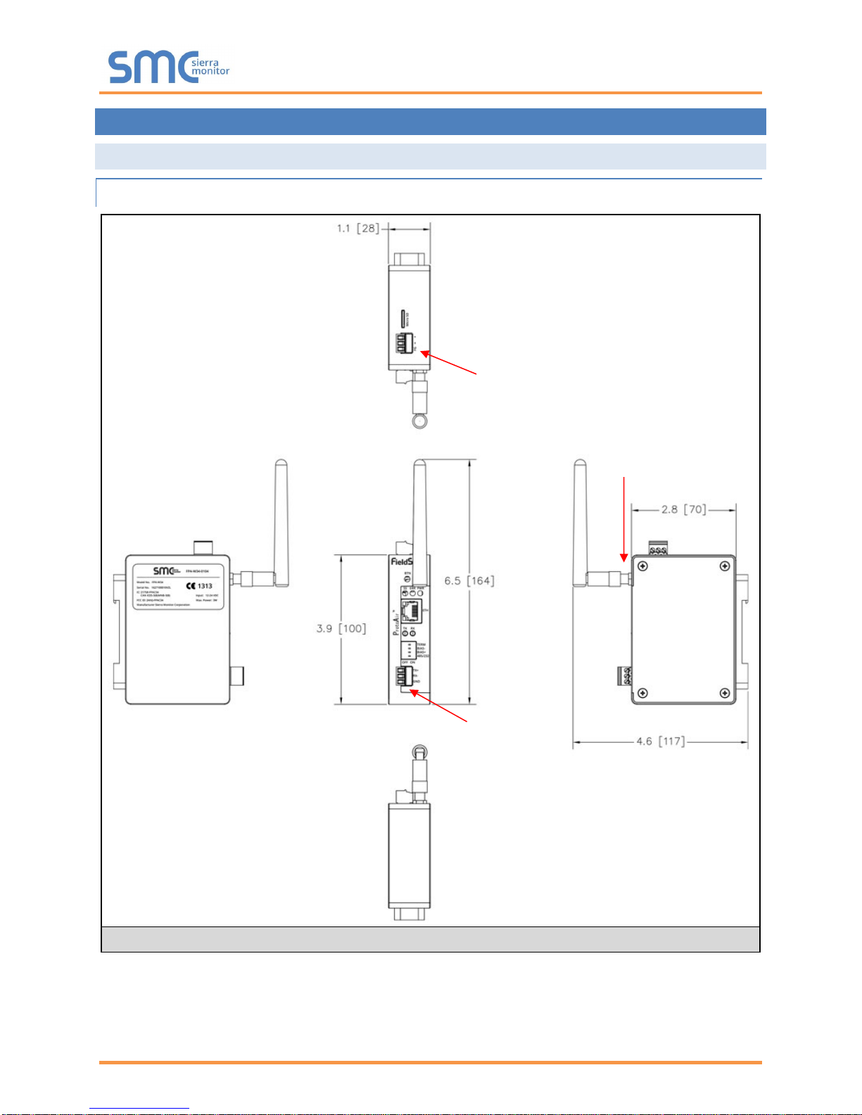
2.1.1 FS-IOT-BACW Drawing
Figure 1: BACnet IoT Gateway FS-IOT-BACW Dimensions
P1 Serial Port
Power Port
Wi-Fi Antenna
Socket
BACnet IoT Gateway Start-up Guide
Page 9 of 60
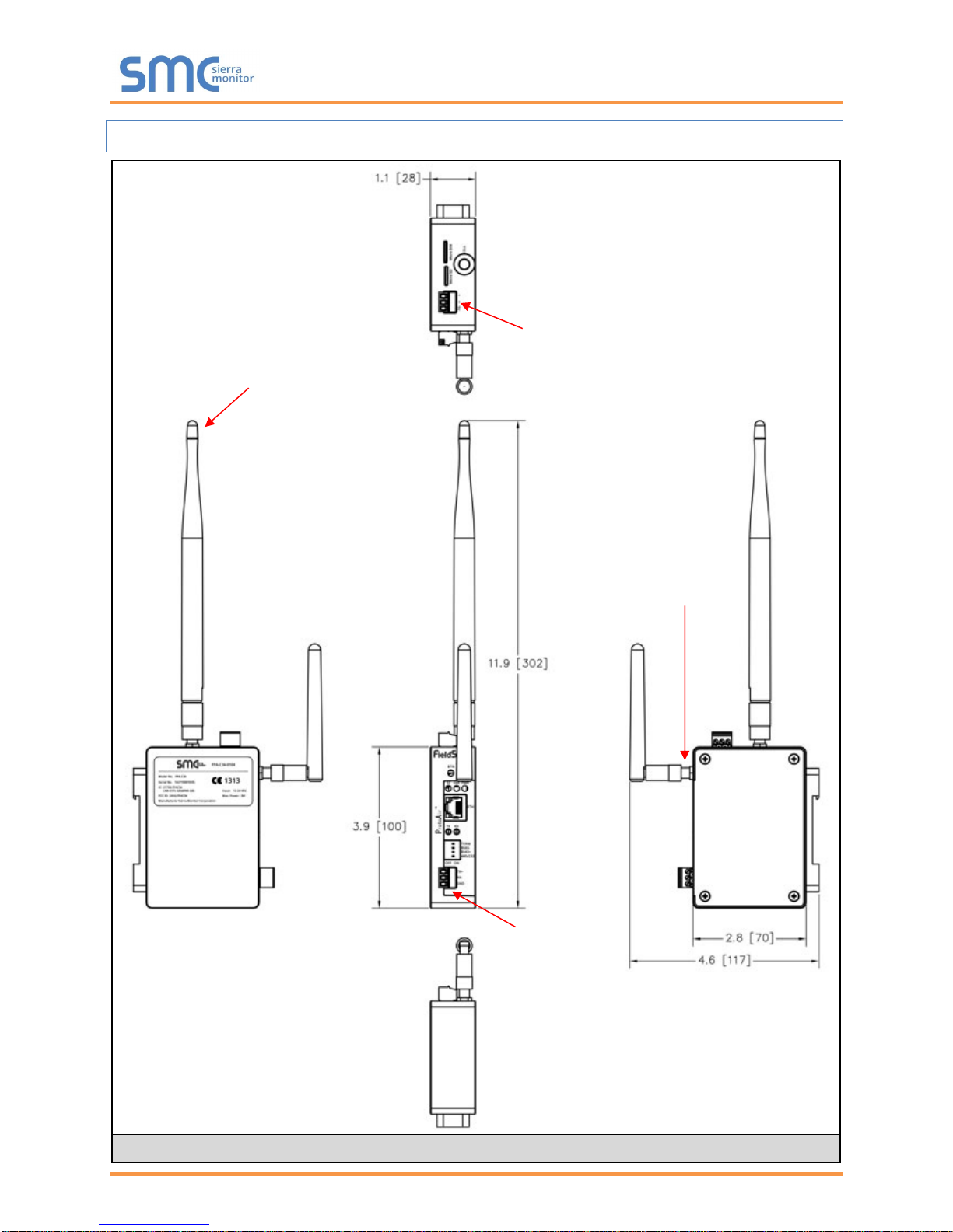
2.1.2 FS-IOT-BACC Drawing
Figure 2: BACnet IoT Gateway FS-IOT-BACC Dimensions
P1 Serial Port
Power Port
Cellular Antenna
Wi-Fi Antenna
Socket
BACnet IoT Gateway Start-up Guide
Page 10 of 60
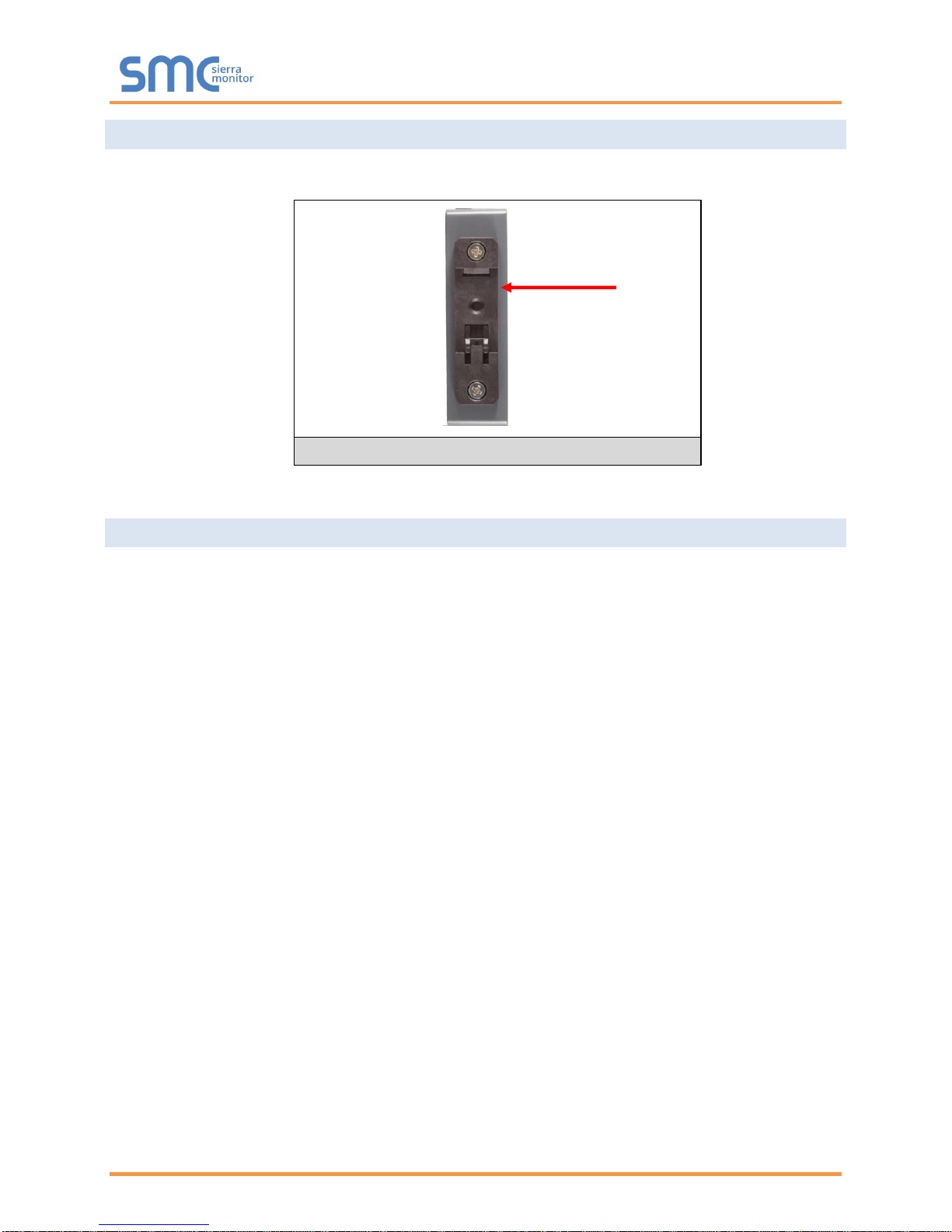
2.2 Mounting
The BACnet IoT Gateway can be mounted using the DIN rail mounting bracket on the back of the unit.
2.3 Attaching the Antenna(s)
Wi-Fi Antenna:
If using the FS-IOT-BACW (Wi-Fi) or FS-IOT-BACC (Cellular & Wi-Fi) models, screw in the Wi-Fi antenna
to the front of the unit as shown in Figure 1.
Cellular Antenna:
If using the FS-IOT-BACC model, screw in the long cellular antenna on the top of the unit as shown in
Figure 2.
Din Rail
Bracket
Figure 3: DIN Rail
BACnet IoT Gateway Start-up Guide
Page 11 of 60
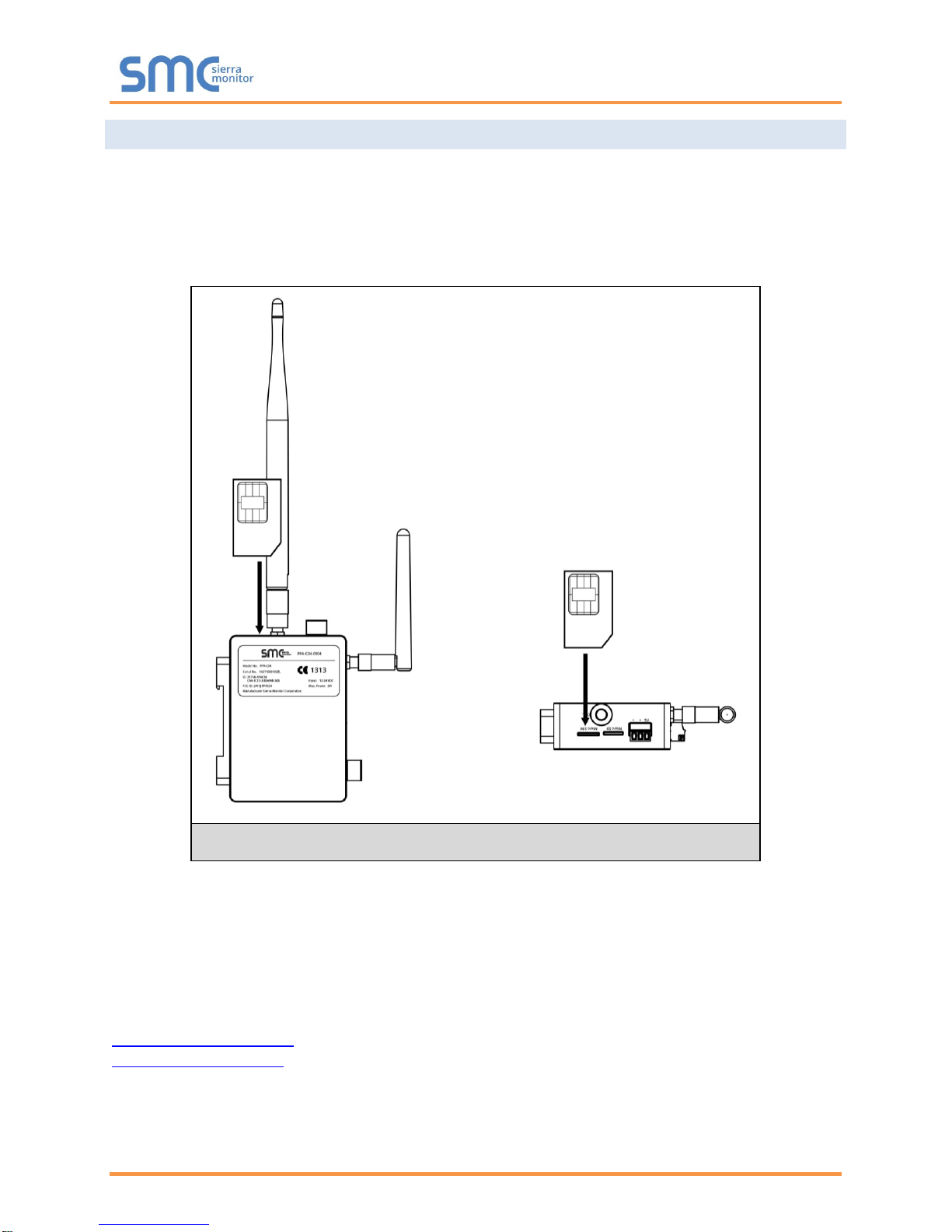
2.4 FS-IOT-BACC: Inserting the SIM Card
NOTE: A micro 3G SIM card must be purchased from an AT&T, Kore Telematics or Vodafone
cellular provider to set up Cellular functionality and create a data plan for the BACnet IoT
Gateway. SIM card vendor contact information is available at the end of the Section.
Insert the SIM card into the Micro SIM card slot with the chip on the SIM card facing away from the
cellular antenna as shown below.
See Section 6 to complete cellular setting configuration.
SIM Card Vendor Contact Information:
Kore Telematics
Joao Freitas
KORE Wireless
Office: (669) 600-5360
jfreitas@korewireless.com
www.koretelematics.com
AT&T
Please call AT&T Customer Service at 800.331.0500 or find the nearest AT&T store.
IMEI 357178070517852
Figure 4: Insert SIM Card into the Micro SIM Card Slot –
Label Side View (Left) and Top Down View (Right)
BACnet IoT Gateway Start-up Guide
Page 12 of 60
3 INSTALLING THE BACNET IOT GATEWAY
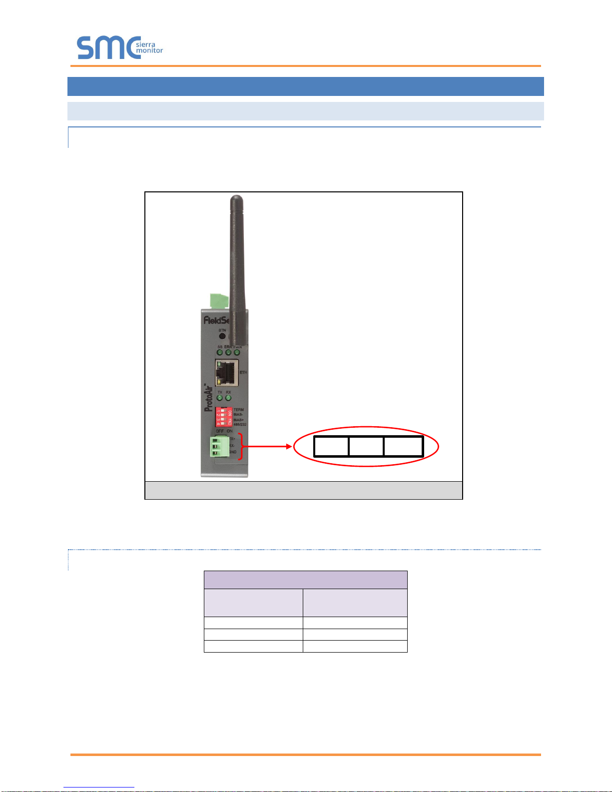
3.1 RS-485
3.1.1 Connection P1 Port
NOTE: Ensure RS-485 is selected by checking that the number 4 DIP Switch is set to the left side.
Connect to the 3-pin connector as shown below.
The following Baud Rates are supported on the P1 Port:
9600, 19200, 38400, 57600, 76800
3.1.1.1 Wiring
RS-485
BMS RS-485 Wiring
BACnet IoT Gateway
Pin Assignment
RS-485 +
TX +
RS-485 -
RX -
GND
GND
NOTE: Use standard grounding principles for GND.
Figure 5: RS-485 R2 Connection Port
TX+ RX- GND
BACnet IoT Gateway Start-up Guide
Page 13 of 60
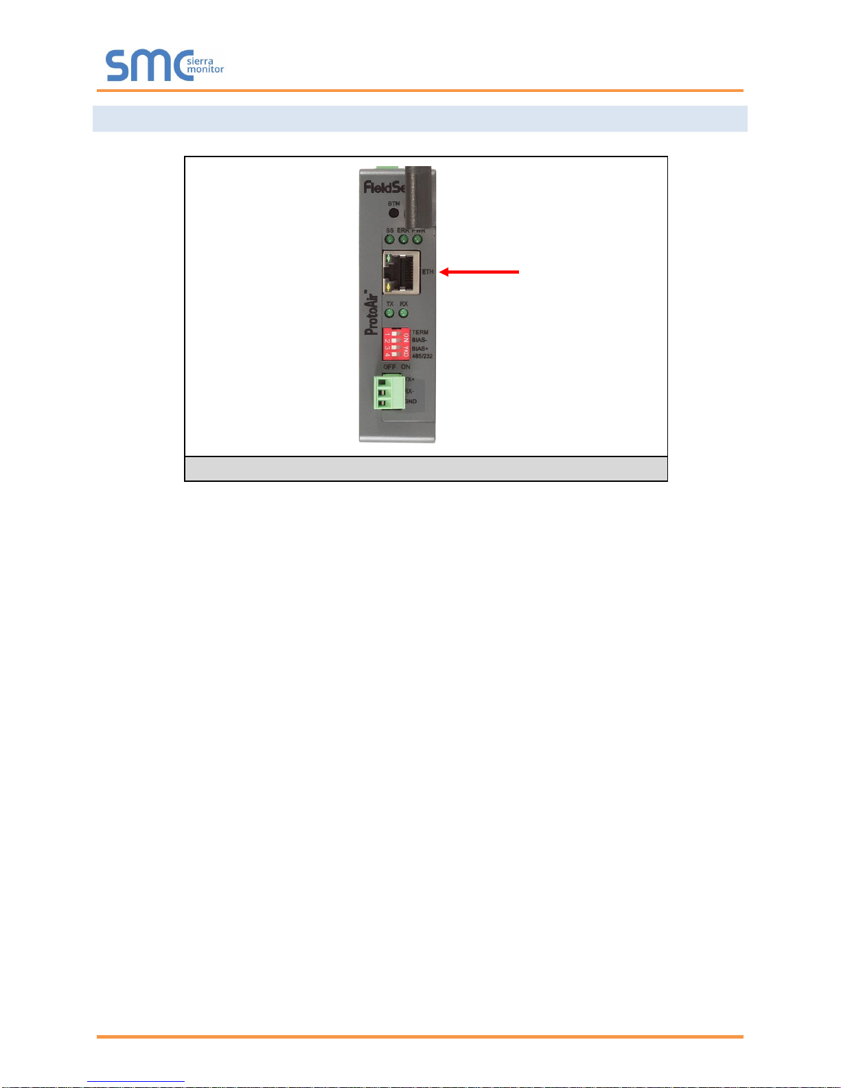
3.2 10/100 Ethernet Connection Port
The Ethernet Port is used both for BACnet/IP communications and for configuring the BACnet IoT Gateway
via the Web App. To connect the BACnet IoT Gateway, either connect the PC to the Gateway’s Ethernet
port or connect the Gateway and PC to an Ethernet switch. Use CAT5 cables for the connection.
NOTE: The Default IP Address of the BACnet IoT Gateway is 192.168.1.24, Subnet Mask is
255.255.255.0.
Figure 6: Ethernet Connection
Ethernet Port
BACnet IoT Gateway Start-up Guide
Page 14 of 60
4 OPERATION
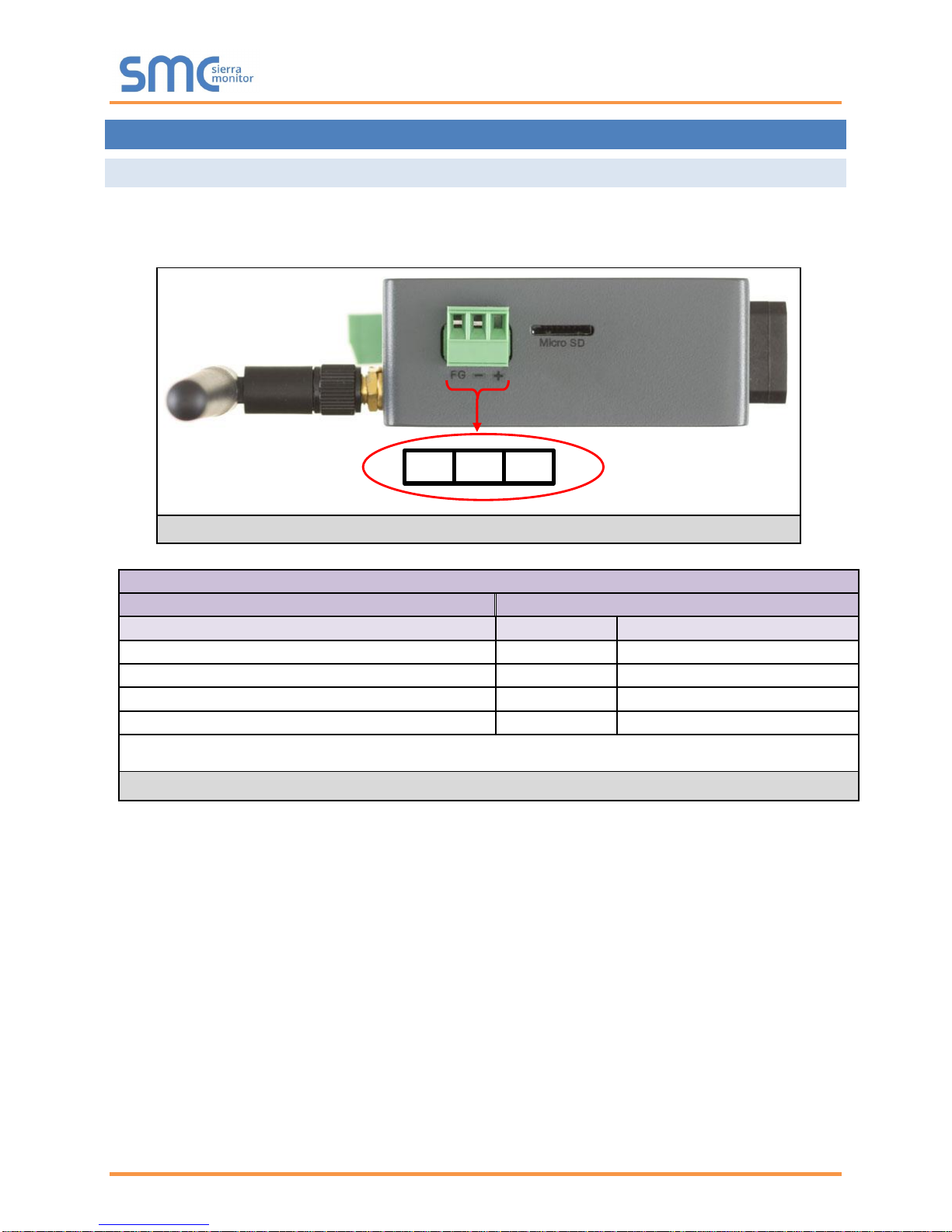
4.1 Power up the Device
Apply power to the device. Ensure that the power supply used complies with the specifications provided.
Ensure that the cable is grounded using the FG or “Frame GND” terminal. The BACnet IoT Gateway is
powered by 12-24V DC.
Power Requirement for BACnet IoT Gateway External Gateway
Current Draw Type
BACnet IoT Gateway Family
12V DC
24V DC
FS-IOT-BACW (Typical)
170mA
100mA
FS-IOT-BACW (Maximum)
240mA
140mA
FS-IOT-BACC (Typical)
320mA
185mA
FS-IOT-BACC (Maximum)
670mA
390mA
NOTE: These values are ‘nominal’ and a safety margin should be added to the power supply of the host
system. A safety margin of 25% is recommended.
Figure 8: Required Current Draw for the BACnet IoT Gateway
Figure 7: Connecting Power
FG
– +
BACnet IoT Gateway Start-up Guide
Page 15 of 60
5 CONNECTING TO THE BACNET IOT GATEWAY
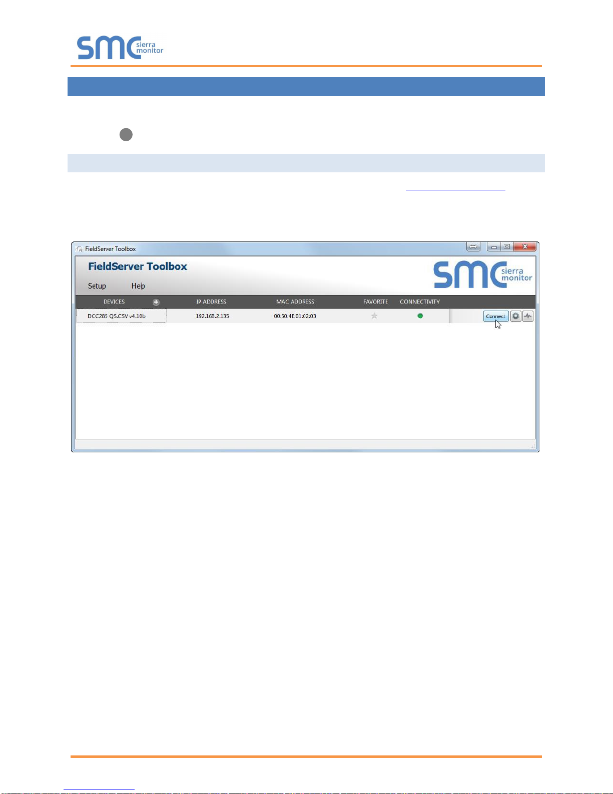
The FieldServer Toolbox Application can be used to discover and connect to the BACnet IoT Gateway on
a local area network. To manually connect to the BACnet IoT Gateway using the Toolbox, click on the plus
icon ( ) and enter the IP Address, or enter the Internet IP Address into a web browser.
5.1 Using the FieldServer Toolbox
• Install the Toolbox application from the USB drive or get it from the Sierra Monitor website.
• Use the Toolbox application to find the BACnet IoT Gateway, change the IP Address details (if
required) and launch the Web App (by clicking the Connect button).

BACnet IoT Gateway Start-up Guide
Page 16 of 60
5.2 Connect Using a Web Browser
• Open a Web Browser and input the BACnet IoT Gateway’s IP Address. The Default IP Address of
the BACnet IoT Gateway is 192.168.1.24, Subnet Mask is 255.255.255.0.
• If the PC and the BACnet IoT Gateway are on different IP Networks, assign a Static IP Address to
the PC on the 192.168.2.X network.
Figure 9: BACnet IoT Gateway Login Page

BACnet IoT Gateway Start-up Guide
Page 17 of 60
5.3 Logging into BACnet IoT Gateway
• Click the orange “Login” button and enter user name and password informaiton into the Login
Window.
NOTE: The default user name is “admin” and default password is “admin”.
• The BACnet IoT Gateway landing page will open once valid user information has been entered and
the “Log In” button is clicked.
Figure 10: Login Window
Figure 11: BACnet IoT Gateway Landing Page

BACnet IoT Gateway Start-up Guide
Page 18 of 60
5.3.1 Change Password
• Once logged in, click on the profile dropdown menu ( ) in the top right corner of any
page.
• Then click on Settings ( ) to open the Profile Settings window.
• Fill in the old password and the two new password fields, then click the change password button.
• A sucessful password update message will appear, click the “x” in the upper right corner of the
window to exit the Profile Settings window.
5.4 Add Additional Users
• Once in the Profile Settings window, fill in the username, the two password and role fields.
NOTE: An administrator role has full access to the BACnet IoT Gateway and user management,
while a user role does not have user management capability.
• Click the Add User button to save the new user.
5.5 Manage Users
• When more than one user is generated for the BACnet IoT Gateway, the Manage Users field will
appear in the Profile Settings window.
Figure 12: Profile Settings Window
Figure 13: Manage Users Settings

BACnet IoT Gateway Start-up Guide
Page 19 of 60
NOTE: Only administrators are able to see and edit the Manage User fields.
• To edit a user entry, select a specific user from the dropdown menu.
• This opens up multiple fields that allow editing of user information.
• Select the action to perform:
o Reset user password – Fill in the two password fields and click the Reset Password button
o Change user role – Select the desired role in the dropdown menu and click the Change Role
button
o Delete user – Simply click the Delete User button and the user entry will be deleted
Figure 14: Select User
Figure 15: Edit User Information

BACnet IoT Gateway Start-up Guide
Page 20 of 60
6 CONFIGURING THE BACNET IOT GATEWAY
6.1 Settings
By default, the BACnet IoT Gateway will open up on the BACnet Explorer page (Figure 11). Navigate to
the settings by clicking on the Settings button, found along the left side of the page. The BACnet IoT
Gateway settings are split up into three types: Local Settings, Remote Settings and Network Settings.
The table below describes how the buttons at the bottom of each page function.
Button
Definition
Save
Click to save settings. Saving will require the device to be restarted.
Refresh
Click to clear the current settings before saving; if settings have been saved the
Refresh button is unavailable.
Defaults
Click to change settings back to factory defaults.
Figure 16: Configuration Button Functions
The following sections explain the setting parameters by type for BACnet IoT Gateway configuration.
6.1.1 Network Settings
The IP Settings for the BACnet IoT Gateway are used by BACnet/IP. The IP Settings can be edited in the
Network Settings section as shown.
NOTE: Common Settings make it possible to choose the primary connection when both Ethernet
and Wi-Fi Client connections are available.
Figure 17: Network Settings – Common and IP Settings

BACnet IoT Gateway Start-up Guide
Page 21 of 60
Scroll down to view and edit the Wi-Fi Client, Wi-Fi Access Point, and Cellular Settings.
NOTE: Cellular Settings are only available on FS-IOT-BACC models.
Figure 18: Network Settings – Wi-Fi Client, Wi-Fi AP, and Cellular Settings

BACnet IoT Gateway Start-up Guide
Page 22 of 60
6.1.2 Local Settings – BACnet
Enter the fields for the settings described below as needed:
Parameter
Definition
All Connections
Network Number
The BACnet network number for the connection. Legal values are 1-65534.
Each network number must be unique across the entire BACnet internetwork.
The Internal Network Number is used for internal BACnet traffic and has to be
unique across the BACnet network.
BACnet/IP Settings
IP Port
The BACnet/IP default is 47808 (0xBAC0), but other port numbers can may be
specified.
BACnet MS/TP Settings
MAC Address
Legal values are 0-127, must be unique on the physical network.
Max Master
The highest MAC address to scan for other MS/TP master devices. The default
of 127 is guaranteed to discover all other MS/TP master devices on the network.
Max Info Frames
The number of transactions the BACnet IoT Gateway may initiate while it has the
MS/TP token. Default is 50.
BAUD Rate
The serial baud rate used on the network.
Token Usage Timeout (ms)
The number of milliseconds the router will wait before deciding that another
master has dropped the MS/TP token. This value must be between 20ms and
100ms. Choose a larger value to improve reliability when working with slow
MS/TP devices that may not be able to meet strict timing specifications.
Figure 20: Connection Parameters
Figure 19: Connection Settings

BACnet IoT Gateway Start-up Guide
Page 23 of 60
6.1.3 Remote Settings – Foreign Device Registration for BBMD Support
The BACnet IoT Gateway uses “Foreign Device Registration” or “FDR” to communicate to BACnet/IP
devices on another network. Follow the instructions below to enable FDR between the BACnet IoT Gateway
and a remote network:
• Click the “Enabled” checkbox under the Foreign Device Registration section of the BACnet
Settings.
• Enter the Remote BACnet Router’s externally mapped IP Address and BACnet/IP Port to the
appropriate Foreign Device Registration fields. This allows the BACnet IoT Gateway to discover
BACnet devices on the remote network.
NOTE: The user must uncheck the “Enabled” checkbox to allow the BACnet IoT Gateway to
discover on the local network.
NOTE: See Appendix B for additional details concerning FDR and BBMD.
Figure 21: FDR Enabled Checkbox
Figure 22: FDR IP Fields

BACnet IoT Gateway Start-up Guide
Page 24 of 60
7 USING THE BACNET IOT GATEWAY
Sections 7.1 – 7.4 represent each of the first four tabs that appear across the left side of the page once
logged into the BACnet IoT Gateway and describe their functions.
7.1 BACnet Explorer
Click on the BACnet Explorer tab on the left side of the page to open the BACnet Explorer page.
Figure 23: BACnet Explorer Page

BACnet IoT Gateway Start-up Guide
Page 25 of 60
7.1.1 Discover the Device List
• To discover the devices connected to the same subnet as the BACnet IoT Gateway, click the
Discover button (binocular icon).
• This will open the Discovery window, click the checkboxes next to the desired discovery settings
and click Discover to start the search.
NOTE: The “Discover All Devices” or “Discover All Networks” checkboxes must be unchecked to
search for a specific device range or network.
NOTE: Allow the devices to populate before interacting with the device list for optimal
performance. Any discovery or explore process will cause a green message to appear in
the upper right corner of the browser to confirm that the action is complete.
Figure 25: Device List
Figure 24: Discovery Window

BACnet IoT Gateway Start-up Guide
Page 26 of 60
7.1.2 View Device Details and Explore Points/Parameters
• To view the device details, click the blue plus sign ( ) next to the desired device in the list.
o This will show only some of the device properties for the selected aspect of a device
• To view the full details of a device, highlight the device directly (in Figure 27 “1991
WeatherLink_1”) and click the Explore button ( ) that appears to the right of the highlited
device as a magnifying glass icon or double-click the highlighted device.
o Now additional device details are viewable; however, the device can be explored even further
Figure 26: Device Sub-items
Figure 27: Full Device Sub-items

BACnet IoT Gateway Start-up Guide
Page 27 of 60
• Click on one of the device details.
• Then click on the Explore button that appears or double-click the device object.
A full list of the device details will appear on the right side window. If changes are expected since the last
explore, simply press the Refresh button ( ) that appears to right of individual properties to refresh the
value.
NOTE: The Gateway Search Bar will find devices based on their Device ID.
NOTE: The Gateway Discovery Tree has 3 levels that correspond to the following.
• Network number
o Device
▪ Device object
Figure 28: Simplified Device Details
Figure 29: Additional Device Details

BACnet IoT Gateway Start-up Guide
Page 28 of 60
7.1.3 Ex p l ore All of a Device’s Points – Deep Explore
• To explore all device objects under a specific device with one search, click the desired device to
highlight it.
• Then click the three white dots ( ) that appear to the right of the highlighted device to open a
dropdown menu.
• Click Deep Explore to open the Deep Explore window.
• Select which property types to find in the search.
NOTE: The “all” selection must be unchecked to show object-name, present-value and
status-flags as options.
NOTE: Object-name will always be checked in a Deep Explore search.
• Click the Explore button and wait for the green explore complete message to comfirm all points
have been discovered.

BACnet IoT Gateway Start-up Guide
Page 29 of 60
7.1.4 Checking Device Information – Device Info
• To check a device’s properties/information, click the desired device to highlight it.
• Then click the three white dots ( ) that appear to the right of the highlighted device to open a
dropdown menu.
• Click Device Info to open the Device Info window and get the device information needed.

BACnet IoT Gateway Start-up Guide
Page 30 of 60
7.1.5 Edit the Present Value Field
The only recommended field to edit via BACnet IoT Gateway is the device’s present value field.
NOTE: Other BACnet properties are editable (such as object name, object description, etc.);
however, this is not recommended because the BACnet IoT Gateway is not a Building
Management System (BMS).
• To edit the present value, select it in the property listings.
• Then click the Write button ( ) on the right of the property to bring up the Write Property
window.
Figure 31: Write Property Window
Figure 30: Highlighted Present Value

BACnet IoT Gateway Start-up Guide
Page 31 of 60
• Enter the appropriate change and click the Write button.
The window will close. When the BACnet Explorer page appears, the present value will be
changed as specified.
Figure 32: Updated Present Value

BACnet IoT Gateway Start-up Guide
Page 32 of 60
7.2 Monitor View
7.2.1 Set Devices to Track
Before using the Monitor View page, device properties must be selected to be monitored for analysis and
testing in the BACnet Explorer page. To do so follow the instructions below:
• When viewing the expanded device properties on the BACnet Explorer page, click the checkbox to
the left of any property to track.
• Once all properties are selected for that data type, click the monitor button to set the
selected properties to be monitored.
o The Monitor column in the selected property row will change from “Off” to “On”
• Wait for the configuration to complete, then click on the Monitor View tab.
Figure 34: Highlighted Monitor View Tab
Figure 33: Selected Device Properties for Monitor View

BACnet IoT Gateway Start-up Guide
Page 33 of 60
7.2.2 Logging Data
• To log data for Historian, Event Log and SMC Cloud, click the checkbox under the Log column.
• Click on the graph icon ( ) to the right of the listed data elements to open the Data Logging
window.
• Select the type of logging for the data point and set the logging interval, COV threshold value or
COV max scan time as they apply then click the Save button to save the settings.
Figure 35: Monitor View Showing Tracked Device Properties
Figure 38: Periodic Log Type
Figure 37: Change of Value Log Type
Figure 36: Data Logging Window

BACnet IoT Gateway Start-up Guide
Page 34 of 60
• To change the poll interval of a device, click the Settings button (see Figure 35) to
open the Settings window.
• Click the Edit icon to open the Edit Poll Interval window.
• Make desired changes and click Save.
NOTE: Up to 30 days of data can be recorded and stored.
NOTE: Click the Trash icon ( ) to the right of any logged property to remove it from Monitor
View.
Figure 40: Edit Poll Interval Window
Figure 39: Settings Window

BACnet IoT Gateway Start-up Guide
Page 35 of 60
7.3 Historian
NOTE: Historian can log up to 8,000 data points.
• Click the Historian tab on the left side of the page.
7.3.1 Graph Data Logging Information
• Click on the Settings button ( ) to select data to graph.
• Click the checkbox next to the data element to graph.
o Any combination of elements can be selected
NOTE: A data element is only visible when it is set for data logging as shown in Section 7.2.
Figure 41: Historian Page
Figure 42: Historian Settings Window

BACnet IoT Gateway Start-up Guide
Page 36 of 60
• Click Submit to generate a graph for each element selected.
o To delete a log, check the boxes next to the properties to delete and click the delete button;
then click “Yes” to confirm
• After a few seconds the graph should appear.
To view individual values of data, scroll across the graph to show a text box that states each exact point
and the location of that point on the graph via a blue dot.
To view a graph of only select dates/time frames, move the cursor towards the miniature version of the
graph that is shown just below the full size graph. Hover the cursor over the miniature graph so that the
cursor becomes a crosshair ( ).
Click and hold near the beginning or ending time frame desired, then drag the crosshair towards the ending
or beginning time frame; all within the confines of the miniature graph.
Figure 44: Historian Graph
Figure 43: Confirm Clear Logs Window

BACnet IoT Gateway Start-up Guide
Page 37 of 60
The full-size version of the graph will populate accordingly.
Any additional edits to the time frame can be adjusted by clicking and dragging the wedge markers on either
side of the highlighted portion of the miniature graph.
To go back to the full graph, click on any faded portion of the miniature graph.
NOTE: The data selected in Historian is also available via SMC Cloud RESTful API, contact SMC
Technical Support for a copy of the RESTful API Start-up Guide.
Figure 45: Selected Portion of Historian Graph

BACnet IoT Gateway Start-up Guide
Page 38 of 60
7.3.2 Creating an Event Log
• To create an event log for a property, click on the Monitor View tab to go to the Monitor View
page.
• Click the bell icon ( ) to the right of the property to log and the Event Settings window will open.
• Click on the Add Event button to change the event settings.
• Set the event as needed and click Save.
Figure 47: Event Settings Window
Figure 48: Add Event Settings
Figure 46: Monitor View Device Properties

BACnet IoT Gateway Start-up Guide
Page 39 of 60
• Repeat this process to create more events as needed.
NOTE: Click the Trash icon ( ) to the right of any event to remove it.
• Click the “x” in the top right corner of the Event Settings window to close it.
o The Monitor View page will now update the status column as events take place
Figure 49: Event Settings Window with Added Events
Figure 50: Monitor View Device Properties with Updated Status

BACnet IoT Gateway Start-up Guide
Page 40 of 60
7.4 Event Log
Click the Event Log tab on the left side of the page to open the Event Logger and view the events that have
been set to track in Section 7.3.2 (by time and type with a descriptive message).
Figure 51: Event Log Page Showing Added Events

BACnet IoT Gateway Start-up Guide
Page 41 of 60
8 CONNECTING TO THE SMC CLOUD
8.1 User Setup
Request an invitation to SMC Cloud from the manufacturer’s support team and follow the instructions below
to set up login details:
• The “Welcome to FieldPoP” email will appear as shown below.
NOTE: If no SMC Cloud email was received, check the spam/junk folder for an email from
notification@fieldpop.io. Contact the manufacturer’s support team if the email cannot be
found.
Figure 52: Welcome to FieldPoP Email

BACnet IoT Gateway Start-up Guide
Page 42 of 60
• Click the “Complete Registration” button and fill in user details accordingly.
• Fill in the name, phone number and password fields.
• Click “Save” to save the user details.
• Record the email account used and password for future use.
Figure 53: Setting User Details

BACnet IoT Gateway Start-up Guide
Page 43 of 60
8.2 Registration Process
Once SMC Cloud user credentials have been generated, the BACnet IoT Gateway can be registered onto
the SMC Cloud server.
• Click on the FieldPoP™ tab on the left-hand side of the screen.
• The following informational splash page will appear, click Close to view the registration page.
Figure 54: BACnet IoT Gateway Landing Page – FieldPoP Tab
Figure 55: Registration Information Page

BACnet IoT Gateway Start-up Guide
Page 44 of 60
• If a warning message appears instead of the splash page, follow the suggestion that appears on
screen.
• If the BACnet IoT Gateway cannot reach the SMC Cloud server, the following message will appear.
o Follow the directions presented in the warning message and check that the DNS settings are
set up with the following Domain Name Server (DNS) settings:
DNS1=8.8.8.8
DNS2=8.8.4.4
o Ensure that the BACnet IoT Gateway is properly connected to the Internet
NOTE: If changes to the network settings are done, remember to click “Update IP Settings” and
then power cycle the BACnet IoT Gateway.
Figure 56: SMC Cloud Connection Problems Message

BACnet IoT Gateway Start-up Guide
Page 45 of 60
• On the registration page, fill in user credentials and all other device information fields for registration
of each individual BACnet IoT Gateway in the field.
• To input the device location do one of the following:
o Enter the address in the address field
o Click the “Get Current Location” button to auto-populate
NOTE: This button will only work if location services have been enabled on the local browser. If
using the Chrome browser and connected via LAN, this method will not work.
o Drop a location directly on the Google map
o Enter the latitude and longitude manually
• Click Register Device.
Figure 57: SMC Cloud Registration Page

BACnet IoT Gateway Start-up Guide
Page 46 of 60
• Once the device has successfully been registered, the following screen will appear listing the device
details and additional information auto-populated by the BACnet IoT Gateway.
Figure 58: Device Registered for SMC Cloud

BACnet IoT Gateway Start-up Guide
Page 47 of 60
8.3 Login to SMC Cloud
After the BACnet IoT Gateway is registered, go to www.fieldpop.io and type in the appropriate login
information as per registration credentials.
If the login password is lost, see the SMC Cloud Start-up Guide for recovery instructions.
NOTE: For additional SMC Cloud instructions see the SMC Cloud Start-up Guide.
Figure 59: SMC Cloud Login Page
Figure 60: SMC Cloud Landing Page

BACnet IoT Gateway Start-up Guide
Page 48 of 60
APPENDIX A SPECIFICATIONS
FS-IOT-BACW & FS-IOT-BACC1
Available Ports
One RS-485 +/- ground port One power +/- frame ground port
One Ethernet 10/100 BaseT port
Power Requirements
Input Voltage: 12-24V DC BACW Current draw: @ 12V, 240 mA
Power Rating: 2.5 Watts BACC Current draw: @ 12V, 670 mA
Approvals
CE and FCC Class B & C Part 15, TUV approved to UL 60950, IC Canada, RoHS
Compliant, PTCRB and CTIA
Dimensions (WxDxH)
4 x 1.1 x 2.7 in (10.16 x 2.8 x 6.8 cm)
Weight
0.4 lbs (0.2 Kg)
Operating Temperature
-20 to 70oC (-4 to 158oF)
Humidity
10-95% RH non-condensing
Wi-Fi 802.11 b/g/n
Frequency: 2.4 GHz Channels: 1 to 11 (inclusive)
Antenna Type: SMA Encryption: TKIP, WPA & AES
Cellular 2
Features: 3G & GPS Antenna Type: SMA
HSDPA: Up to 21.0 Mbps HSUPA: Up to 5.76 Mbps
IMEI: 357178070517852
Figure 61: Specifications
“This device complies with part 15 of the FCC Rules. Operation is subject to the following two conditions:
• This device may not cause harmful interference
• This device must accept any interference received, including interference that may cause undesired
operation.
NOTE: This equipment has been tested and found to comply with the limits for a Class A digital device,
pursuant to part 15 of the FCC Rules These limits are designed to provide reasonable protection against
harmful interference when the equipment is operated in a commercial environment This equipment
generates, uses, and can radiate radio frequency energy and, if not installed and used in accordance with
the instruction manual, may cause harmful interference to radio communications Operation of this
equipment in a residential area is likely to cause harmful interference in which case the user will be required
to correct the interference at his expense
Modifications not expressly approved by FieldServer could void the user's authority to operate the
equipment under FCC rules”.
1
Specifications subject to change without notice.
2
Only for FS-IOT-BACC.

BACnet IoT Gateway Start-up Guide
Page 49 of 60
APPENDIX B REFERENCES
Appendix B.1. Understanding FDR
The BACnet IoT Gateway doesn’t allow FDR, local IP and BACnet MS/TP to co-exist because there is no
guarantee that two distinct BACnet networks will have unique Device Instances or Network Numbers.
(Unique Device Instances and Network Numbers are a requirement for BACnet to function properly). If local
and remote options were allowed concurrently, the BACnet IoT Gateway would connect two networks that
are probably not designed to work together. Forcing this situation would create extremely difficult to
diagnose problems.
Appendix B.2. Understanding BACnet BBMD and NAT Routing
The BACnet IoT Gateway does not support NAT routing. However, the BACnet IoT Gateway must have
the external IP Address and IP Port that the NAT router assigns to it, because these are inserted into the
BACnet/IP BVLC header as the source IP Address which a remote recipient can use to reach the BBMD
(BACnet Broadcast Management Device). This is necessary because the messages are distributed again
by a remote BBMD, and the remote recipient of a distributed broadcast needs to reach the originator of the
broadcast.
Figure 62: BBMD Scenario 1 – Interconnected IP Network

BACnet IoT Gateway Start-up Guide
Page 50 of 60
With NAT Routing, BBMD alone does not work because the Devices cannot reach each other’s IP
Addresses even if they know them. The only reachable address is the BBMD itself, so this must also act as
a BACnet IoT Gateway to forward traffic to the intended device. When this is done, the destination device’s
IP Address and Port are encoded as the DADR in the network header, so that the Router can forward
messages to the correct device.
Figure 63: BBMD Scenario 2 – NAT Routing

BACnet IoT Gateway Start-up Guide
Page 51 of 60
APPENDIX C TROUBLESHOOTING
Appendix C.1. Communicating with the BACnet IoT Gateway Over the Network
• Confirm that the network cabling is correct.
• Confirm that the computer network card is operational and correctly configured.
• Confirm that there is an Ethernet adapter installed in the PC’s Device Manager List, and that it is
configured to run the TCP/IP protocol.
• Check that the IP netmask of the PC matches the BACnet IoT Gateway. The Default IP Address of
the BACnet IoT Gateway is 192.168.1.24, Subnet Mask is 255.255.255.0.
o Go to Start|Run
o Type in “ipconfig”
o The account settings should be displayed.
o Ensure that the IP Address is 192.168.1.X and the netmask 255.255.255.0
• Ensure that the PC and BACnet IoT Gateway are on the same IP Network, or assign a Static IP
Address to the PC on the 192.168.1.X network.

BACnet IoT Gateway Start-up Guide
Page 52 of 60
Appendix C.2. Lost or Incorrect IP Address
• Ensure that FieldServer Toolbox is loaded onto the local PC. Otherwise, download the
FieldServer-Toolbox.zip via the Sierra Monitor website’s Software Downloads.
• Extract the executable file and complete the installation.
• Connect a standard CAT5 Ethernet cable between the user’s PC and BACnet IoT Gateway.
• Double click on the FS Toolbox Utility and click Discover Now on the splash page.
• Check for the IP Address of the desired gateway.
• If correcting the IP Address of the gateway: click the settings icon on the same row as the
gateway, then click Network Settings, change the IP Address and click Update IP Settings to save.
Ethernet Port
Figure 64: Ethernet Port Location

BACnet IoT Gateway Start-up Guide
Page 53 of 60
Appendix C.3. Viewing Diagnostic Information
• Type the IP Address of the BACnet IoT Gateway into the web browser or use the FieldServer
Toolbox to connect to the BACnet IoT Gateway.
• Click on the blue “Diagnostics” text at the bottom of the page, next to the SMC copyright.
• Under the Navigation panel, click on view and then on connections.
NOTE: If there are any errors showing on the Connection page, refer to Appendix C.4 for the
relevant wiring and settings.
Appendix C.4. Checking Wiring and Settings
No COMS on the Serial side. If the Tx/Rx LEDs are not flashing rapidly then there is a COM issue. To fix
this problem, check the following:
• Visual observations of LEDs on the BACnet IoT Gateway (Appendix C.5)
• Check baud rate, parity, data bits, stop bits
• Check Sieral device address
• Verify wiring
• Verify device is connected to the same subnet as the BACnet IoT Gateway
No COMS on the Ethernet protocol. To fix this, check the following:
• Visual observations of LEDs on the BACnet IoT Gateway (Appendix C.5)
• Check device address
• Verify wiring
• Verify device is connected to the same subnet as the BACnet IoT Gateway
• Verify IP Address setting
NOTE: If the problem still exists, a Diagnostic Capture needs to be taken and sent to support.
(Appendix C.6)
Figure 65: Error Messages Screen

BACnet IoT Gateway Start-up Guide
Page 54 of 60
Appendix C.5. LED Diagnostics for Communications Between BACnet IoT Gateway and Devices
See the diagram below for LED locations to BACnet IoT Gateway.
Tag
Description
SS
The SPL LED will light if the unit is not getting a response from one or more of the configured devices.
ERR
The SYS ERR LED will go on solid indicating there is a system error on unit. If this occurs, immediately
report the related “system error” shown on the error screen of the FS-GUI to support for evaluation.
PWR
This is the power light and should show steady green at all times when the unit is powered.
TX
The TX LED will flash when a message is received on the serial port on the 3-pin connector.
If the serial port is not used, this LED is non-operational.
RX
The RX LED will flash when a message is sent on the serial port on the 3-pin connector.
If the serial port is not used, this LED is non-operational.
Figure 66: Diagnostic LEDs
Diagnostic LEDs

BACnet IoT Gateway Start-up Guide
Page 55 of 60
Appendix C.6. Before Contacting Technical Support Take a Diagnostic Capture
When a problem occurs that cannot be resolved with regular troubleshooting, take a log via the
FieldServer FS-GUI. Send this log together with a detailed description of the problem to
support@sierramonitor.com for evaluation. The Diagnostic Capture will allow us to rapidly
diagnose the problem.
• Open the FieldServer FS-GUI page.
• Click on Diagnostics in the Navigation panel.
• Go to Full Diagnostic and select the capture period.
• Click the Start button under the Full Diagnostic heading to start the capture.
o When the capture period is finished, a Download button will appear next to the Start button
• Click Download for the caputure to be downloaded to the local PC.
• Email the diagnostic zip file to technical support (support@sierramonitor.com).

BACnet IoT Gateway Start-up Guide
Page 56 of 60
Appendix C.7. Updating Firmware
To load a new version of the firmware, follow these instructions:
1. Extract and save the new file onto the local PC.
2. Open a web browser and type the IP Address of the FieldServer in the address bar.
NOTE: Default IP Address is 192.168.1.24.
NOTE: Use the FS Toolbox utility if the IP Address is unknown (Appendix C.2).
3. Click on the “Diagnostics & Debugging” button.
4. In the Navigation Tree on the left-hand side, do the following:
a. Click on “Setup”
b. Click on “File Transfer”
c. Click on the “Firmware” tab
5. In the Firmware tab, click on “Choose Files” and select the firmware file extracted in step 1.
6. Click on the orange “Submit” button.
7. When the download is complete, click on the “System Restart” button.

BACnet IoT Gateway Start-up Guide
Page 57 of 60
Appendix C.8. Securing BACnet IoT Gateway with Passwords
Access to the BACnet IoT Gateway can be restricted by enabling a password on the FS-GUI Passwords
page – click Setup and then Passwords in the navigation panel. There are 2 access levels defined by 2
account names: Admin and User.
• The Admin account has unrestricted access to the BACnet IoT Gateway.
• The User account can view any BACnet IoT Gateway information, but cannot make any changes
or restart the BACnet IoT Gateway.
The password needs to be a minimum of eight characters and is case sensitive.
If the password is lost, click cancel on the password authentication popup window, and email the password
recovery token to support@sierramonitor.com to receive a temporary password from the support team.
Access the BACnet IoT Gateway to set a new password.
Figure 68: Password Recovery Page
Figure 67: FS-GUI Passwords Page

BACnet IoT Gateway Start-up Guide
Page 58 of 60
Appendix C.9. Kaspersky Endpoint Security 10
If Kaspersky Endpoint Security 10 is installed on the user’s PC, the software needs to be modified to allow
the PC to register bridges on SMC Cloud.
NOTE: This problem is specific to KES10, Kaspersky 2017 does not have this problem.
To fix the problem, the BACnet IoT Gateway (http://192.168.100.85/* in Figure 70) must be set as a trusted
URL to the "Web Anti-Virus"->"Settings" as shown below.
Figure 69: Kaspersky ES10 Settings
Figure 70: Web Anti-Virus Trusted URLs

BACnet IoT Gateway Start-up Guide
Page 59 of 60
Appendix C.10. Wi-Fi and Cellular Signal Strength
Wi-Fi
Cellular
<60dBm – Excellent
< 60dBm – Excellent
<70dBm – Very good
<70dBm – Very good
<80dBm – Good
<80dBm – Good
>80dBm – Weak
<90dBm – Weak
>90dBm – Spotty; not good for data
Figure 71: Wi-Fi & Cellular Signal Strength Listing
NOTE: If the signal is weak or spotty, try to improve the signal strength by checking the antenna
and the ProtoAir position.

BACnet IoT Gateway Start-up Guide
Page 60 of 60
APPENDIX D LIMITED 2 YEAR WARRANTY
Sierra Monitor Corporation warrants its products to be free from defects in workmanship or material under
normal use and service for two years after date of shipment. Sierra Monitor Corporation will repair or replace
any equipment found to be defective during the warranty period. Final determination of the nature and
responsibility for defective or damaged equipment will be made by Sierra Monitor Corporation personnel.
All warranties hereunder are contingent upon proper use in the application for which the product was
intended and do not cover products which have been modified or repaired without Sierra Monitor
Corporation’s approval or which have been subjected to accident, improper maintenance, installation or
application; or on which original identification marks have been removed or altered. This Limited Warranty
also will not apply to interconnecting cables or wires, consumables or to any damage resulting from battery
leakage.
In all cases Sierra Monitor Corporation’s responsibility and liability under this warranty shall be limited to
the cost of the equipment. The purchaser must obtain shipping instructions for the prepaid return of any
item under this warranty provision and compliance with such instruction shall be a condition of this warranty.
Except for the express warranty stated above, Sierra Monitor Corporation disclaims all warranties with
regard to the products sold hereunder including all implied warranties of merchantability and fitness and
the express warranties stated herein are in lieu of all obligations or liabilities on the part of Sierra Monitor
Corporation for damages including, but not limited to, consequential damages arising out of/or in connection
with the use or performance of the product.
 Loading...