

SMC Sierra Monitor FS-8704-14 Driver Manual

Driver Version: 1.12
Document Revision: 4.D
FieldServer
FS-8704-14 EtherNet/IP
Driver Manual
(Supplement to the FieldServer Instruction Manual)
APPLICABILITY & EFFECTIVITY
Effective for all systems manufactured after May 2018.

EtherNet/IP Driver Manual
Contact Information
Technical Support
Please call us for any technical support needs related to the FieldServer product.
Sierra Monitor Corporation
1991 Tarob Court
Milpitas, CA 95035
Website: www.sierramonitor.com
U.S. Support Information:
+1 408 964-4443
+1 800 727-4377
Email: support@sierramonitor.com
EMEA Support Information:
+44 2033 1813 41
Email: support.emea@sierramonitor.com

EtherNet/IP Driver Manual
Table of Contents
TAB L E OF CONTENTS
1 EtherNet/IP desciription ...................................................................................................................... 5
2 Driver Scope of Supply ....................................................................................................................... 5
2.1 Supplied by Sierra Monitor Corporation ......................................................................................... 5
3 Hardware Connections ........................................................................................................................ 6
4 Data Array Parameters ........................................................................................................................ 7
5 Configuring the FieldServer as an EtherNet/IP Client...................................................................... 8
5.1 Client Side Connection Parameters ............................................................................................... 8
5.2 Client Side Node Parameters ......................................................................................................... 9
5.3 Client Side Map Descriptor ............................................................................................................. 9
5.3.1 FieldServer Related Map Descriptor Parameters ................................................................... 9
5.3.2 Driver Related Map Descriptor Parameters – Unconnected Messages ............................... 10
5.3.3 Driver Related Map Descriptor Parameters – Data Table Read/Write ................................. 11
5.3.4 Driver Related Map Descriptor Parameters – PCCC ............................................................ 12
5.3.5 Driver Related Map Descriptor Parameters – Implicit IO Messages ..................................... 12
5.3.6 Timing Parameters ................................................................................................................ 12
5.3.7 Map Descriptor Example 1: Unconnected Messages ........................................................... 13
5.3.8 Map Descriptor Example 2: Data Table Messages ............................................................... 13
5.3.9 Map Descriptor Example 3: PCCC Messages ...................................................................... 13
5.3.10 Map Descriptor Example 4: Implicit IO Messages ................................................................ 13
6 Configuring the FieldServer as an EtherNet/IP Server .................................................................. 14
6.1 Server Side Connection Parameters ............................................................................................ 14
6.2 Server Side Node Parameters ...................................................................................................... 14
6.3 Server Side Map Descriptor ......................................................................................................... 15
6.3.1 FieldServer Specific Map Descriptor Parameters ................................................................. 15
6.3.2 Server Specific Map Descriptor Parameters – Unconnected Messages .............................. 15
6.3.3 Server Specific Map Descriptor Parameters – Data Table Read/Write ................................ 16
6.3.4 Driver Related Map Descriptor Parameters – PCCC ............................................................ 17
6.3.5 Server Specific Map Descriptor Parameters – Implicit IO Messages ................................... 17
6.3.6 Map Descriptor Example 1: Unconnected Messages ........................................................... 18
6.3.7 Map Descriptor Example 2: Data Table Messages ............................................................... 18
6.3.8 Map Descriptor Example 3: PCCC Messages ...................................................................... 18
6.3.9 Map Descriptor Example 4: Implicit IO Messages ................................................................ 18
Appendix A Useful Features .................................................................................................................... 19
Appendix A.1 General Notes ................................................................................................................... 19
Appendix A.2 FieldServer as an Adapter and Scanner ........................................................................... 19
Appendix A.3 Common Paths ................................................................................................................. 19
Appendix A.4 Setting the Data Type for Stored Data .............................................................................. 19
Appendix A.4.1 Transfer Binary Values Using EIP .............................................................................. 19
Appendix A.5 Configuring a PLC to Read/Write Data to/from the FieldServer with Explicit Messaging 19
Appendix A.5.1 FieldServer Configuration File .................................................................................... 20
Appendix A.5.2 The PLC Program ...................................................................................................... 21
Appendix A.6 Configuring a FieldServer to Read/Write Data to/from a PLC with Explicit Messaging ... 23
Appendix A.6.1 FieldServer Configuration File .................................................................................... 24
Appendix A.6.2 The PLC Program ...................................................................................................... 25
Appendix A.7 Read/Write Structures and Value of EIP_Structure_Handle ............................................ 25
Appendix A.8 Implicit Messaging ............................................................................................................ 27
Appendix A.8.1 Configuring a PLC to Read and Write Data to and from the FieldServer .................. 27
Appendix A.8.1.1 FieldServer Configuration File ............................................................................ 28
Appendix A.8.1.2 The PLC Setup ................................................................................................... 29
Appendix A.8.2 EDS AOP ................................................................................................................... 30
Appendix A.9 Configuring the PLC with a FieldServer EDS File ............................................................ 33
Appendix B Troubleshooting ................................................................................................................... 37
Appendix B.1 Firmware Update Downloading ........................................................................................ 37

EtherNet/IP Driver Manual
Table of Contents
Appendix C Vendor Information .............................................................................................................. 38
Appendix C.1 ControlLogix ...................................................................................................................... 38
Appendix C.2 Connection Information – Allen Bradley Message Blocks ................................................ 38
Appendix C.3 FieldServer Not Recognized by RSlinx ............................................................................ 38
Appendix C.4 Using EIP Data_Types with RSLogix ............................................................................... 38
Appendix D Reference .............................................................................................................................. 39
Appendix D.1 Error Messages ................................................................................................................ 39
Appendix D.2 Classes and Attributes Supported .................................................................................... 39
Appendix D.3 Error Codes ...................................................................................................................... 41

EtherNet/IP Driver Manual
Page 5 of 42
1 ETHERNET/IP DESCIRIPTION
The EtherNet/IP (EIP) driver allows the FieldServer to transfer data to and from devices over Ethernet
using the EtherNet/IP protocol. The FieldServer can emulate either a Server or Client.
EtherNet/IP uses CIP (Control and Information Protocol), the common network, transport and application
layers also shared by ControlNet and DeviceNet. EtherNet/IP then makes use of standard Ethernet and
TCP/IP technology to transport CIP communications packets. The result is a common, open application
layer on top of open and highly popular Ethernet and TCP/IP protocols.
The Driver is able to read/write using the Data Table structure employed by all Logix Series PLC’s.
PCCC support is also provided for legacy devices that do not fully support CIP encapsulation. EIP PCCC
Encapsulation was tested at the Sierra Monitor factory using a PLC5 I785 ENET card. The following data
types were tested:
• N
• F
• S
The Driver also supports PCCC communication on SLC and MicroLogix (Tested on MicroLogix 1400
Device).
Fragmented Services (0x52) is supported for data_table read and write operations.
The driver supports only Logical Binary Addressing. The remote device should be configured to use
Logical Binary Addressing.
The default EtherNet/IP TCP Port is 44818.
The information that follows describes how to expand upon the factory defaults provided in the
configuration files included with the FieldServer.
2 DRIVER SCOPE OF SUPPLY
2.1 Supplied by Sierra Monitor Corporation
PART #
Description
FS-8915-10
UTP cable (7 foot) for Ethernet connection
EtherNet/IP Driver Manual
Page 6 of 42
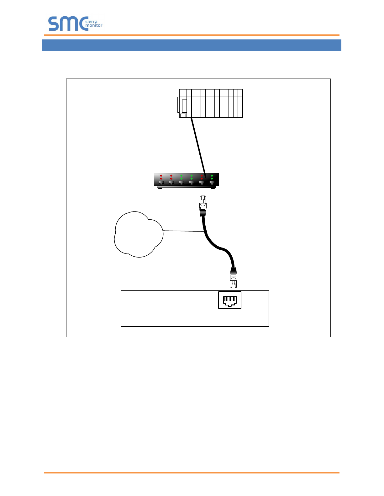
3 HARDWARE CONNECTIONS
It is possible to connect an EtherNet/IP device to either port N1 or N2 on the FieldServer. These ports
must just be configured to use EtherNet/IP in the configuration file.
FieldServer
FieldServer Part #
8915-10
UTP cable
Connect to an Ethernet Port
on the FieldServer
N1
19
Switch
Remote EtherNet/IP
Device

EtherNet/IP Driver Manual
Page 7 of 42
4 DATA ARRAY PARAMETERS
Data Arrays are “protocol neutral” data buffers for storage of data to be passed between protocols. It is
necessary to declare the data format of each of the Data Arrays to facilitate correct storage of the relevant
data.
Section Title
Data_Arrays
Column Title
Function
Legal Values
Data_Array_Name
Provide name for Data Array.
Up to 15
alphanumeric
characters
Data_Array_Format
Provide data format. Each Data Array can only take on
one format.
FLOAT, BIT, UInt16,
SInt16, Byte
Data_Array_Length
Number of Data Objects. Must be larger than the data
storage area required by the Map Descriptors for the data
being placed in this array.
1-10, 000
Example
// Data Arrays
Data_Arrays
Data_Array_Name
, Data_Array_Format
, Data_Array_Length
DA_AI_01
, UInt16
, 200
DA_AO_01
, UInt16
, 200
DA_DI_01
, Bit
, 200
DA_DO_01
, Bit
, 200
DA_OUTPUTS
, UInt16
, 3
DA_INPUTS
, UInt16
, 8
DA_Config
, UInt16
, 1

EtherNet/IP Driver Manual
Page 8 of 42
5 CONFIGURING THE FIELDSERVER AS AN ETHERNET/IP CLIENT
For detailed information on FieldServer configuration, refer to the FieldServer Configuration Manual. The
information that follows describes how to expand upon the factory defaults provided in the configuration
files included with the FieldServer.
This section documents and describes the parameters necessary for configuring the FieldServer to
communicate with an EtherNet/IP Server.
The configuration file tells the FieldServer about its interfaces, and the routing of data required. In order to
enable the FieldServer for EtherNet/IP communications, the driver independent FieldServer buffers need
to be declared in the “Data Arrays” section, the destination device addresses need to be declared in the
“Client Side Nodes” section, and the data required from the servers needs to be mapped in the “Client Side
Map Descriptors” section. Details on how to do this can be found below.
NOTE: In the tables below, * indicates an optional parameter and bold legal values are defaults.
5.1 Client Side Connection Parameters
Section Title
Adapter
Column Title
Function
Legal Values
Adapter
Adapter Name
N1, N2
1
Protocol
Specify protocol used.
EtherNet/IP
UDP_Local_IO_Port
Specify if it is required to receive implicit
IO messages on the non-default port.
1-65534, 2222
Example
// Client Side Connections
Adapters
Adapter
, Protocol
, UDP_Local_IO_Port
N1
, EtherNet/IP
, 2222
1
Not all ports shown are necessarily supported by the hardware. Consult the appropriate Instruction manual for details of the ports
available on specific hardware.

EtherNet/IP Driver Manual
Page 9 of 42
5.2 Client Side Node Parameters
Section Title
Nodes2
Column Title
Function
Legal Values
Node_Name
Provide name for node.
Up to 32 alphanumeric
characters.
IP_Address
Address of Server.
Any valid address on subnet.
Protocol
Specify protocol used.
EtherNet/IP
Adapter
Specify port Adapter used.
N1, N21
Plc_Type*
Specify the type of remote PLC. Only required
for PCCC Services.
MicroLogix, SLC5, PLC5
EIP_Cache_Connection*
Specify if connection to remote server should
be reused or closed after every data transfer
transaction.
YES, NO
EIP_Skip_Cmd*
Some devices do not support all 'under the
hood' commands specified by the EIP driver.
Specify the command that should not be
issued by the FieldServer.
-, LIST_IDENTIFY
Example
// Client Side Nodes
Nodes
Node_Name
, IP_Address
, Adapter
, Protocol
PLC 1
, 192.168.1.174
, N1
, EtherNet/IP
5.3 Client Side Map Descriptor
5.3.1 FieldServer Related Map Descriptor Parameters
Column Title
Function
Legal Values
Map_Descriptor_Name
Name of this Map
Descriptor.
Up to 32 alphanumeric characters.
Data_Array_Name
Name of Data Array where
data is to be stored in the
FieldServer.
One of the Data Array names from Section
4.
Data_Array_Offset
Starting location in Data
Array.
0 to (Data_Array_Length -1) as specified in
Section 4.
Function
Function of Client Map
Descriptor.
Rdbc, Wrbc, Wrbx
NOTE: It is possible with Data Table Read on
the Client side to read and write to the same
tag by using the "Write Thru" property of the
Rdbc function.
2
Only one explicit connection is created per node. All explicit Map Descriptors for that node will use the same explicit connection.

EtherNet/IP Driver Manual
Page 10 of 42
5.3.2 Driver Related Map Descriptor Parameters – Unconnected Messages
Column Title
Function
Legal Values
EIP_Service
The action to be performed.
Get_Attrib, Set_Attrib
EIP_Class
Class to be polled.
0-65535, default 0 (refer to
Appendix D.2 for commonly
used classes)
EIP_Attribute
Attribute associated with the class given.
0-255, default 0 (refer to
Appendix D.2 for commonly
used attributes)
EIP_Con_Typ
The type of data transfer required. Also referred to
as the “Transport Method”.
Unconnected, Explicit
EIP_Path*
Used to stipulate the path to the CPU in certain
PLC’s. Paths vary and are dependent on the
structure of the network.
Any space delimited numerical
value. Refer to vendor’s
device documentation.
(Appendix A.3)
EIP_Data_Type
This parameter should be used to force the data
type of the attribute to match the data type used
in the remote device.
Value Alias (as used in PLC)
Float REAL
Uint32 DINT
Uint16 INT
BYTE SINT
default INT
Length
Number of data elements to be mapped. If the
number of data elements exceeds the Map
Descriptor length, the list of data elements will be
truncated and an error message will be printed
once per Map Descriptor. Refer to Appendix D for
further information.
For any given Map Descriptor
there can be 200 Floats, 400
Integers or 800 Bytes.
Address
Instance of the class to be polled.
0-65535, default 0

EtherNet/IP Driver Manual
Page 11 of 42
5.3.3 Driver Related Map Descriptor Parameters – Data Table Read/Write
Column Title
Function
Legal Values
EIP_Service
The action to be performed.
Data_Table_Read,
Data_Table_Write
EIP_Con_Typ
The type of data transfer required.
Explicit, UnConnected
EIP_Path*
Used to stipulate the path to the CPU in
certain PLC’s. Paths vary and are dependent
on the structure of the network.
Any space delimited numerical
value. Refer to vendor’s device
documentation. (Appendix
A.3)
EIP_Tag_Name
Tag name expressed in PLC program. The
data type of this parameter is used to set the
data format of the Data Array if the
EIP_DATA_TYPE parameter is not specified.
Maximum length 48
characters.
EIP_Data_Type*
This parameter can be used to force the data
type of the tag to match the data type used in
the remote device. If this parameter is not
specified the Data Type of the Data Array will
be used. Refer to Appendix A.4 for more
information. Data Types can be specified in
either FieldServer or Rockwell Data
Type. Refer to Appendix C.4 for more
information.
Value Alias (as used in PLC)
Float REAL
Uint32 DINT
Uint16 INT
BYTE SINT
BIT BOOL &
BOOLEAN
Length
Number of data elements to be mapped. If the
number of data elements exceeds the Map
Descriptor length, the list of data elements will
be truncated and an error message will be
printed once per Map Descriptor. See
Appendix D for further information.
0 to (Data_Array_Length -1) as
specified in Section 4.
EIP_Structure_Handle*
This parameter is required to read/write
structures. The driver supports read/write
structures having members of same type, i.e.
all members are of type Byte, UINT16,
UINT32 or Float etc.
When this parameter is defined, the number
of structure members must be specified as the
length of the Map Descriptor. Refer to
Appendix A.7 for more information.
Any 16bit Integer number (e.g.
59592), 0

EtherNet/IP Driver Manual
Page 12 of 42
5.3.4 Driver Related Map Descriptor Parameters – PCCC
Column Title
Function
Legal Values
EIP_Service
Action to be performed.
Exec_PCCC (encapsulation
using Allen Bradley PCCC)
EIP_Con_Typ
The type of data transfer required.
Explicit
EIP_Path*
Used to stipulate the path to the CPU in certain
PLC’s. Paths vary and are dependent on the
structure of the network.
Any space delimited
numerical value. Refer to
vendor’s device
documentation. Also see
Appendix A.3, 0 0.
File_Type
Allen Bradley file type.
N Integer
F Float
O Output
B Boolean
I Input
S Status
File_Number
Allen Bradley file number.
Any valid numerical value.
Length
Number of data elements to be mapped. If the
number of data elements exceeds the Map
Descriptor length, the list of data elements will be
truncated and an error message will be printed once
per Map Descriptor. Refer to Appendix D for further
information.
For any given Map Descriptor
there can be 200 floats, 400
integers or 800 bytes.
Address
Address in the file.
Any valid numerical value
between 0 to 255.
5.3.5 Driver Related Map Descriptor Parameters – Implicit IO Messages
Column Title
Function
Legal Values
EIP_Con_Typ
The type of data transfer required. Also
referred to as the “Transport Method”.
Implicit
EIP_Class
EIP class to be polled.
Integer value. In most cases it
will be the assembly class (i.e.
value will be 4).
Address
Production/Consumption connection
point or Instance of the class.
Integer value depending upon
server configuration.
Length
Number of data items to be polled.
For any given Map Descriptor
there can be 125 floats/32bit
integers, 250 integers or 500
bytes.
Parent_Map_Descriptor
Specify the name of previously created
Map Descriptor to which this Map
Descriptor should be linked.
Use – for no setting, or specify
name of other Map Descriptor.
EIP_Real_Time_Format
Specify if real time format is 'HeartBeat'.
Heartbeat, -
5.3.6 Timing Parameters
Column Title
Function
Legal Values
Scan_Interval
Rate at which data is polled
≥0.001s

EtherNet/IP Driver Manual
Page 13 of 42
5.3.7 Map Descriptor Example 1: Unconnected Messages
// Client Side Map Descriptors
Map_Descriptors
Map_Descriptor_Name
, Scan_Interval
, Data_Array_Name
, Data_Array_Offset
, Function
, EIP_Con_Typ
, Node_Name
, EIP_Class
, Address
, EIP_Attribute
, EIP_Service
, Length
CMD_PRO_03
, 0s
, DA_AI_01
, 0
, Rdbc
, Unconnected
, EIP_01
, 10
, 1
, 3
, Get_Attrib
, 1
CMD_PRO_02
, 0s
, DA_AI_01
, 1
, Rdbc
, Unconnected
, EIP_01
, 10
, 2
, 3
, Get_Attrib
, 1
5.3.8 Map Descriptor Example 2: Data Table Messages
// Client Side Map Descriptors
Map_Descriptors
Map_Descriptor_Name
, Scan_Interval
, Data_Array_Name
, Data_Array_Offset
, EIP_Con_Typ
, Node_Name
, Function
, EIP_Service
, EIP_Path
, EIP_Tag_Name
, Length
Cmd_Pro_09
, 0s
, DA_AI_05
, 0
, Explicit
, EIP_01
, Rdbc
, Data_Table_Read
, 1 1
, analog_in_3
, 2
Cmd_Pro_10
, 0s
, DA_AI_06
, 0
, Explicit
, EIP_01
, Rdbc
, Data_Table_Read
, 1 1
, analog_in_4
, 2
5.3.9 Map Descriptor Example 3: PCCC Messages
// Client Side Map Descriptors
Map_Descriptors
Map_Descriptor_Name
, Data_Array_Name
, Data_Array_Offset
, Function
, EIP_Con_Typ
, Node_Name
, EIP_Service
, EIP_Path
, File_Type
, File_Number
, Address
, Length
CMD_01
, DA_F_01
, 0
, Rdbc
, Explicit
, EIP_01
, Exec_PCCC
, 1 0
, F
,8
, 30
, 10
5.3.10 Map Descriptor Example 4: Implicit IO Messages
// Client Side Map Descriptors
Map_Descriptors
Map_Descriptor_Name
, Scan_Interval
, Data_Array_Name
, Data_Array_Offset
, Function
, EIP_Con_Typ
, Node_Name
, EIP_Class
, Address
, Length
, Parent_Map_Descriptor
, EIP_Real_Time_Format
CMD_Producer
, 1s
, DA_OUTPUTS
, 0
, Wrbc
, Implicit
, EIP_01
, 4
, 101
, 3
, -
, -
CMD_Consumer
, 1s
, DA_INPUTS
, 0
, Passive
, Implicit
, EIP_01
, 4
, 102
, 8
, CMD_Producer
, -
CMD_Config
, -
, DA_Config
, 0
, Passive
, Implicit
, EIP_01
, 4
, 103
, 1
, CMD_Producer
, -
To open an implicit
connection, both Producer
and Consumer connection
information is required.
Producer is an active Map
Descriptor, so consumer
should be linked to producer.
The config Map Descriptor
(Rockwell calls it Configuration)
is optional for FieldServer (as
per EIP specs), but it is used by
Controllogix and technically it is
an instance of Assembly Class.
The address numbers
are random, but
should be according
to Server information;
at what numbers
server will consume
and produce data.
If not used or set to “-“: The FieldServer
and remote server both act as producer/
consumer endpoints. If set to 'Heartbeat' on
wrbc MD: The FieldServer acts as a
consumer only endpoint that produces the
heartbeat; the remote server acts as a
producer only end point. If set to
'HeartBeat' on passive MD: The
FieldServer acts as a producer only endpoint
and remote server acts as a consumer only
endpoint that generates a heartbeat.
 Loading...