

Document Revision: 1.E
APPLICABILITY & EFFECTIVITY
Effective for all systems manufactured after June 2016.
ProtoNode Start-up Guide
FPC-N34, FPC-N35, FPC-N36, FPC-N37,
FPC-N38, FPC-N39, FPC-N40, FPC-N41 and FPC-N42

ProtoNode Start-Up Guide
Technical Support
Please call us for any technical support needs related to the FieldServer product.
Sierra Monitor Corporation
1991 Tarob Court
Milpitas, CA 95035
Website: www.sierramonitor.com
U.S. Support Information:
+1 408 262-6611
+1 800 727-4377
Email: support@sierramonitor.com
EMEA Support Information:
+44 2033 1813 41
Email: support.emea@sierramonitor.com
Contact Information

ProtoNode Start-Up Guide
TABLE OF CONTENTS
Table of Contents ........................................................................................................................................................ 3
List of Figures ............................................................................................................................................................. 4
1 Introduction .......................................................................................................................................................... 5
2 Certification .......................................................................................................................................................... 6
2.1 BTL Mark – BACnet Testing Laboratory ........................................................................................................ 6
2.2 LonMark Certification ...................................................................................................................................... 6
3 Bacnet/LONWorks Setup through Protonode .................................................................................................. 7
3.1 Features ......................................................................................................................................................... 7
3.2 Installation Steps for the Customer ................................................................................................................ 7
3.3 Record Identification Data .............................................................................................................................. 7
3.4 Configure the DIP Switches ........................................................................................................................... 8
3.4.1 Setting the Node/ID Device Instance (DIP Switch A0 – A7) ................................................................... 8
3.4.2 Setting the Serial Baud Rate (DIP Switch B0 – B3) ................................................................................ 8
3.4.3 Select and Load Configuration Files ....................................................................................................... 9
4 Interfacing ProtoNode to Host OEM Device ................................................................................................... 10
4.1 ProtoNode FPC-N34 and FPC-N35 Showing Connection Ports.................................................................. 10
4.2 Device Connections to ProtoNode ............................................................................................................... 11
4.3 Resistor and Power Jumper Information ...................................................................................................... 12
4.3.1 Bias Resistors ....................................................................................................................................... 12
4.3.2 Termination Resistor ............................................................................................................................. 13
4.3.3 Power Jumper Settings ......................................................................................................................... 14
4.4 Wiring Field Port to RS-485 BMS Network................................................................................................... 15
4.5 Wiring Field Port to a LonWorks Network .................................................................................................... 15
4.6 Power-Up ProtoNode ................................................................................................................................... 16
5 LonWorks (FPC-N35): Commissioning ProtoNode on a lonworks Network ............................................... 20
5.1 Commissioning ProtoNode FPC-N35 on a LonWorks Network ................................................................... 20
5.1.1 Instructions to Download XIF File from ProtoNode FPC-N35 Using Browser ...................................... 20
6 Connect the ProtoNode’s Web GUI to Setup IP Address for Ethernet Network ......................................... 17
6.1 Connect the PC to ProtoNode via the Ethernet Port .................................................................................... 17
6.2 Setting IP Address for Field Network ........................................................................................................... 18
Appendix A. Troubleshooting.................................................................................................................................. 22
Appendix A.1. Lost or Incorrect IP Address ............................................................................................................ 22
Appendix A.2. Viewing Diagnostic information........................................................................................................ 23
Appendix A.3. Check Wiring and Settings .............................................................................................................. 24
Appendix A.4. LED Diagnostics for Communications Between ProtoNode and Devices ....................................... 25
Appendix A.5. Take Diagnostic Capture With the FieldServer Toolbox ................................................................. 26
Appendix A.6. Update Firmware ............................................................................................................................. 29
Appendix A.7. BACnet: Setting Network_Number for more than one ProtoNode on Subnet ................................. 29
Appendix A.8. Passwords ....................................................................................................................................... 30
Appendix A.9. Reading Data Arrays ....................................................................................................................... 30
Appendix B. Vendor Information ............................................................................................................................. 31
Appendix B.1. Additional DIP switch settings ......................................................................................................... 31
Table of Contents

ProtoNode Start-Up Guide
Appendix C. Reference ............................................................................................................................................. 32
Appendix C.1. Specifications .................................................................................................................................. 32
Appendix C.1.1. Compliance with UL Regulations ........................................................................................... 33
Appendix D. Bank DIP Switch Settings .................................................................................................................. 34
Appendix D.1. “A” Bank DIP Switch Settings .......................................................................................................... 34
Appendix E. Limited 2 Year Warranty ..................................................................................................................... 37
LIST OF FIGURES
Figure 1: A0 - A7 DIP Switches .................................................................................................................................... 8
Figure 2: B0 – B3 DIP Switches.................................................................................................................................... 8
Figure 3: BMS Baud Rate ............................................................................................................................................. 9
Figure 4: S0 – S3 DIP Switches.................................................................................................................................... 9
Figure 5: ProtoNode BACnet FPC-N34 (upper) and ProtoNode FPC-N35 (lower) .................................................... 10
Figure 6: R2 Port ......................................................................................................................................................... 11
Figure 7: Power and RS-485 Connections ................................................................................................................. 11
Figure 8: Bias Resistors .............................................................................................................................................. 12
Figure 9: Termination Resistor.................................................................................................................................... 13
Figure 10: Power Jumper Switch ................................................................................................................................ 14
Figure 11: Connection from ProtoNode to RS-485 Field Network .............................................................................. 15
Figure 12: RS-485 BMS Network EOL Switch ............................................................................................................ 15
Figure 13: LonWorks Terminal.................................................................................................................................... 15
Figure 14: Required current draw for the ProtoNode ................................................................................................. 16
Figure 15: Power Connections.................................................................................................................................... 16
Figure 16: LonWorks Service Pin Location ................................................................................................................. 20
Figure 17: Sample of Fserver.XIF File Being Generated ........................................................................................... 21
Figure 18: Web Configurator screen with Active Profiles ........................................................................................... 18
Figure 19: Changing IP Address via Web GUI ........................................................................................................... 19
Figure 20: Ethernet Port Location ............................................................................................................................... 22
Figure 21: Error messages screen ............................................................................................................................. 23
Figure 22: Diagnostic LEDs ........................................................................................................................................ 25
Figure 23: Ethernet Port Location ............................................................................................................................... 26
Figure 24: Web Configurator – Setting Network Number for BACnet ........................................................................ 29
Figure 25: Additional DIP Switches ............................................................................................................................ 31
Figure 26: Specifications ............................................................................................................................................. 32
Table of Contents

ProtoNode Start-Up Guide
1
2
3
1 INTRODUCTION
ProtoNode is an external, high performance, Building and Industrial Automation multi-protocol
gateway for OEMs wanting to provide protocol translation between Serial and Serial, Serial-Ethernet and
Ethernet-Ethernet devices using LonWorks®1, BACnet®2, Metasys®3 N2 by JCI, Modbus, DNP3, and
more.
This manual provides installation information for 2 types of customers:
OEMs that have purchased the product to be used with their controllers and have not done a first
time start with their controller. When the OEM completes the programming of the ProtoNode with
their device, the ProtoNode will be vitually plug and play at the OEMs customer sites.
o The OEM follows all the steps in this guide to complete the first time start up.
End Users that have purchased the preprogrammed ProtoNode from one of our OEM customers
and need some instructions to configure the device.
The ProtoNode is always pre-configured by the OEM, requiring the end customer to only set of
DIP switches to load a configuration file and set the specific network setting of the device.
NOTE: Technical Support for the end‐user is provided by the device manufacturer and not Sierra
Monitor.
NOTE: For FieldPoP™ information, refer to the FieldPoP™ Device Cloud Start-up Guide online at
the Sierra Monitor.com Resource Center.
www.sierramonitor.com/customer-care/resource-center
LonWorks is a registered trademark of Echelon Corporation
BACnet is a registered trademark of ASHRAE
Metasys is a registered trademark of Johnson Controls Inc.
Page 5 of 37

ProtoNode Start-Up Guide
LonMark International is the recognized authority for certification, education,
and promotion of interoperability standards for the benefit of manufacturers,
integrators and end users. LonMark International has developed extensive
product certification standards and tests to provide the integrator and user with
confidence that products from multiple manufacturers utilizing LonMark
devices work together. Sierra Monitor has more LonMark Certified gateways
than any other gateway manufacturer, including the ProtoCessor, ProtoCarrier
and ProtoNode for OEM applications and the full featured, configurable
gateways.
2 CERTIFICATION
2.1 BTL Mark – BACnet Testing Laboratory
The BTL Mark on the BACnet Router is a symbol that indicates that a product
has passed a series of rigorous tests conducted by an independent laboratory
which verifies that the product correctly implements the BACnet features
claimed in the listing. The mark is a symbol of a high-quality BACnet product.
Go to http://www.BACnetInternational.net/btl/ for more information about the
BACnet Testing Laboratory. Click here for BACnet PIC Statement.
2.2 LonMark Certification
Page 6 of 37

ProtoNode Start-Up Guide
3 BACNET/LONWORKS SETUP THROUGH PROTONODE
3.1 Features
10/100BaseT Ethernet LAN interface (auto-sensing)
Multiple Protocol Support
Supports multiple configuration files and the ability to automatically load any of the stored files for
different OEM controllers or protocols supported.
ProtoNode- FPC-N34/N36/N38 – BACnet BTL Marked
o FPC-N34: 2 RS-485 ports and 1 Ethernet port
o FPC-N36: 1 RS-485 port, 1 Ethernet port and 1 RS-422
o FPC-N38: 1 RS-485 port, 1 Ethernet port and 1 RS-232
ProtoNode- FPC-N35/N37/N39 – LonMark Certified
o FPC-N35: 1 Ethernet Port, 1 LonWorks port and 1 RS-485 port
o FPC-N36: 1 Ethernet port, 1 LonWorks port and 1 RS-422 port
o FPC-N39: 1 Ethernet Port, 1 LonWorks port and 1 RS-232 port
ProtoNode- FPC-N40
o FPC-N40: 1 RS-485 port, 1 Ethernet port and KNX
ProtoNode- FPC-N42
o FPC-N42: 1 RS-485 port, 1 Ethernet port and M-Bus
3.2 Installation Steps for the Customer
1. Record the information about the unit. (Section 3.3)
2. Set the A, B, and S DIP Switch banks for Field Protocol baud rate, Node-ID/Device Instance, and
proper configuration. (Section 3.4)
3. Connect the ProtoNode to the Field Protocol port and customer’s port to the ProtoNode’s RS-485
interface. (Section 4.4)
4. Connect Power to ProtoNode. After power up, the device is installed on BACnet MS/TP or
Metasys N2.
5. Where the Field protocol is BACnet/IP or Modbus TCP/IP, refer to Section 4 to run the
ProtoNode Web GUI program to change the IP Address. No changes to the configuration file are
necessary.
3.3 Record Identification Data
Each ProtoNode has a unique part number located on the side or the back of the unit. The number format
is FPC-N34-XXX-XXX-XXXX. This number should be recorded, as it may be required for technical
support.
Part Number: __________________________________________________
Page 7 of 37
ProtoNode Start-Up Guide
A0
A1
A2
A3
A4
A5
A6
A7
Off On
B0
B1
B2
B3
Off
On
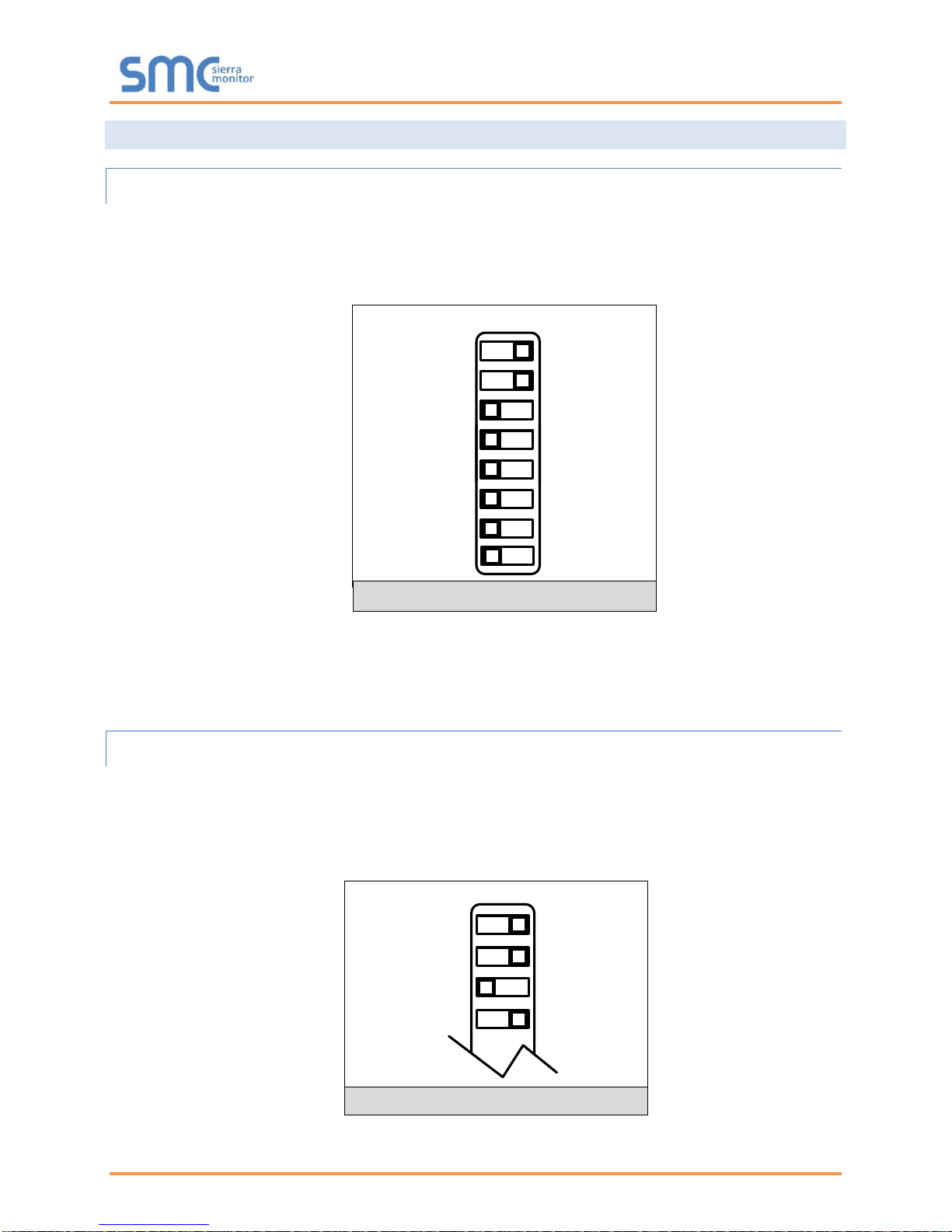
Figure 1: A0 - A7 DIP Switches
Figure 2: B0 – B3 DIP Switches
3.4 Configure the DIP Switches
3.4.1 Setting the Node/ID Device Instance (DIP Switch A0 – A7)
The A Bank DIP switches on the ProtoNode allow users to set the Node-ID/Device Instance on
the Field RS-485.
DIP switches A0 – A7 can also be used to set the MAC Address for BACnet MS/TP and
BACnet/IP.
NOTE: When setting DIP Switches, please ensure that power to the board is OFF.
Refer to Appendix B.1 for the full range of addresses to set Node-ID/Device Instance.
3.4.2 Setting the Serial Baud Rate (DIP Switch B0 – B3)
DIP Switches B0 – B3 can be used to set the serial baud rate to match the baud rate provided by
the interfaced systems.
Metasys N2 is always defaulted to 9600 baud and the B bank is disabled.
“B” bank DIP switches B0 – B3 are disabled on ProtoNode FPC-N35 (LonWorks).
Page 8 of 37
ProtoNode Start-Up Guide
Baud
B0
B1
B2
B3
9600
On
On
On
Off
19200
Off
Off
Off
On
38400*
On
On
Off
On
57600
Off
Off
On
On
76800
On
Off
On
On
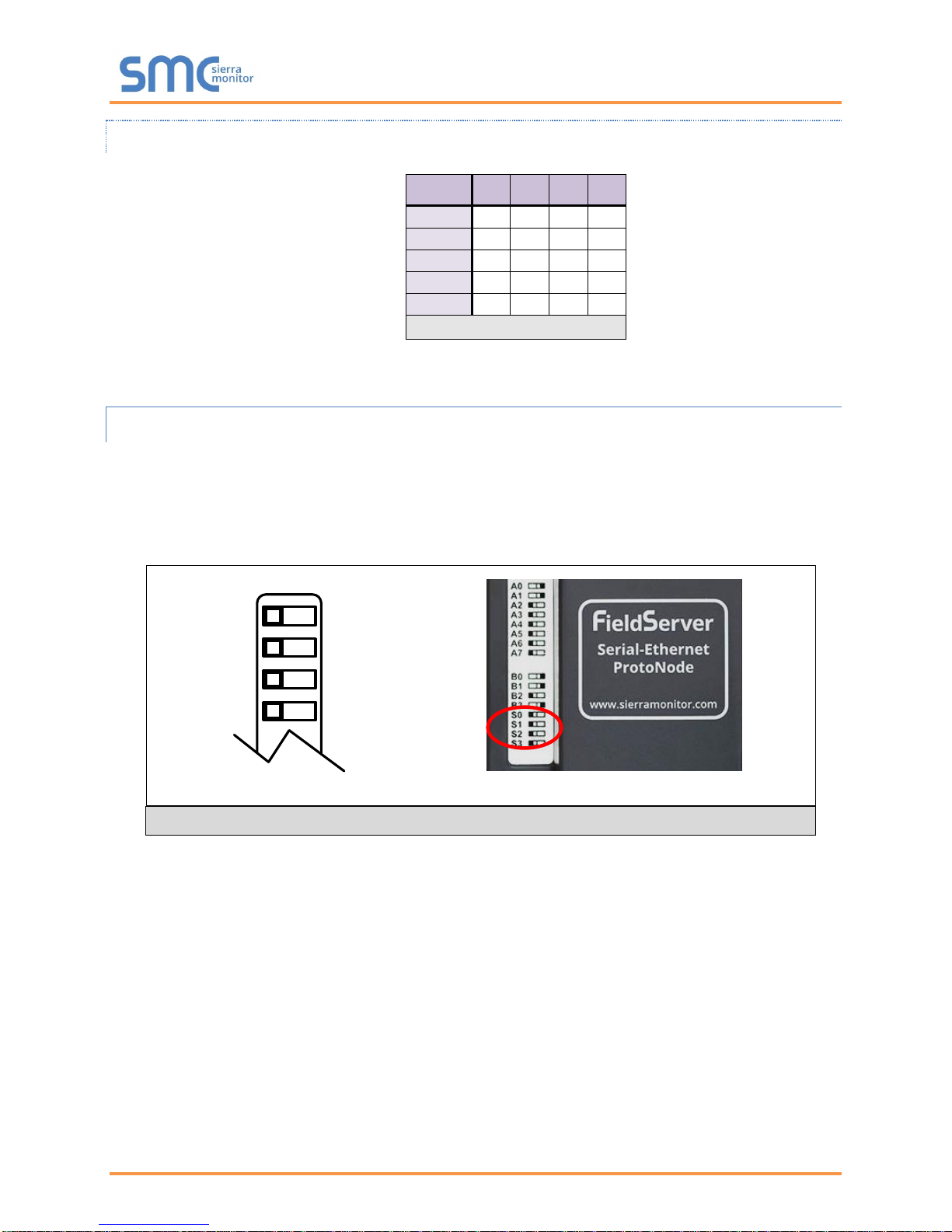
Figure 3: BMS Baud Rate
S Bank DIP Switch Location
Figure 4: S0 – S3 DIP Switches
S0
S1
S2
S3
Off On
S0 – S3 DIP Switches
3.4.2.1 Baud Rate Dip Switch Selection
* Factory default setting = 38400
3.4.3 Select and Load Configuration Files
The S bank of DIP switches, S0 - S3 is used to select and load a configuration file from a group of
pretested/preloaded configuration files that the OEM has programmed for their end users.
End customers will need to go back to the OEM of the device that they are installing to get the
DIP settings for the ProtoNode. The ProtoNode part number will need to be provided to identify
the unit.
Page 9 of 37
ProtoNode Start-Up Guide
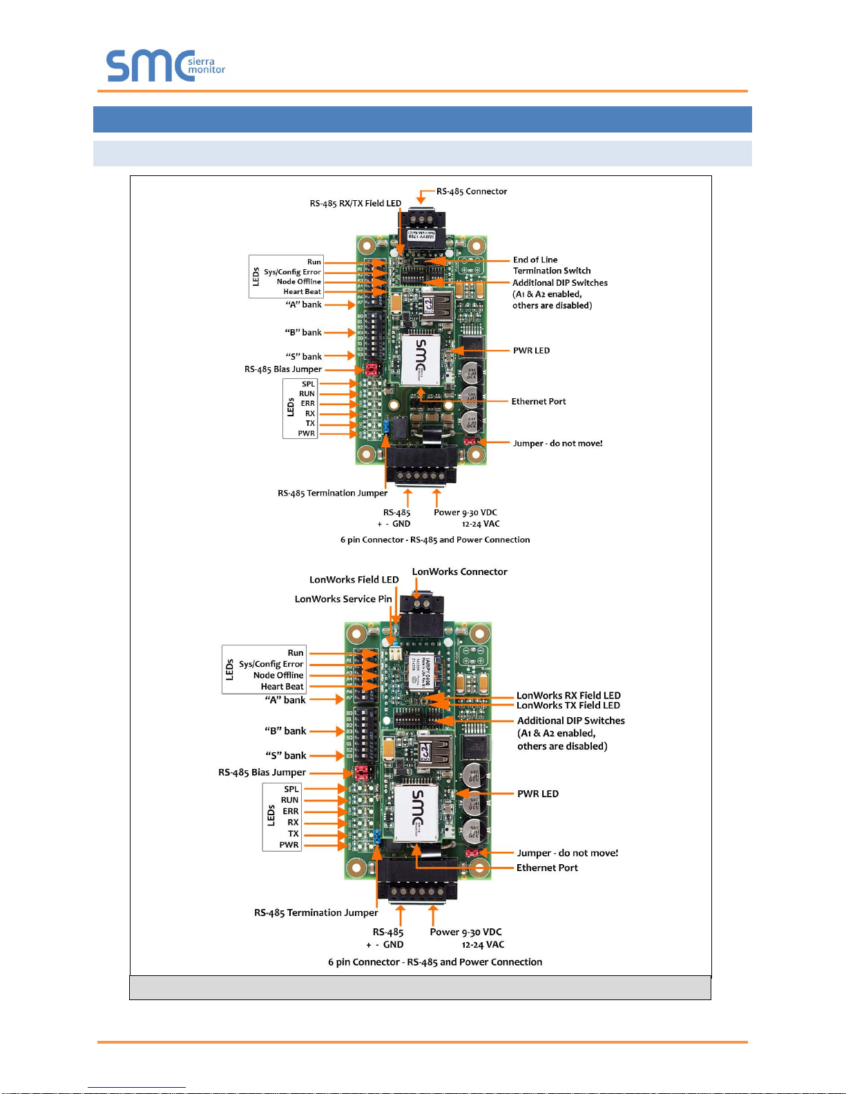
Figure 5: ProtoNode BACnet FPC-N34 (upper) and ProtoNode FPC-N35 (lower)
4 INTERFACING PROTONODE TO HOST OEM DEVICE
4.1 ProtoNode FPC-N34 and FPC-N35 Showing Connection Ports
Page 10 of 37
ProtoNode Start-Up Guide
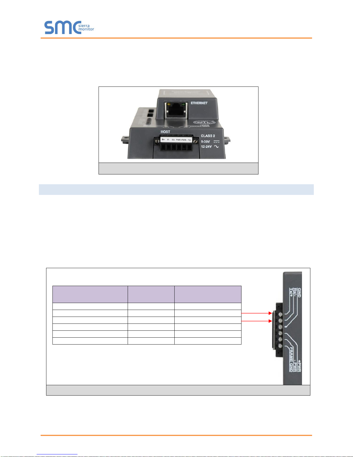
Device Pins
ProtoNode Pin
#
Pin assignment
Pin RS-485 + / RS-232 Tx
Pin 1
RS-485 + / RS-232 Tx
Pin RS-485 - / RS-232 Rx
Pin 2
RS-485 - /RS-232 Rx
Pin GND
Pin 3
RS-485/RS-232 GND
Power In (+)
Pin 4
V +
Power In (-)
Pin 5
V -
Frame Ground
Pin 6
FRAME GND
Figure 6: R2 Port
Figure 7: Power and RS-485 Connections
The top 3 pin port will always be R1, unless it’s a LonWorks ProtoNode in which case the port designation
is LonWorks (and the port is 2 pins). The bottom 6 pin port will be R2.
NOTE: The 6 pin port can be RS-232, RS-485, RS-422 or KNX (and we use the left 3 pins for this as
currently shown).
4.2 Device Connections to ProtoNode
ProtoNode 6 Pin Phoenix connector for RS-485 Devices
The 6 pin Phoenix connector is the same for ProtoNode FPC-N34 (BACnet) and FPC-N35
(LonWorks).
Pins 1 through 3 are for Modbus RS-485 devices.
o The RS-485 GND (Pin 3) is not typically connected
Pins 4 through 6 are for power. Do not connect power until Section 4.6.
Page 11 of 37
ProtoNode Start-Up Guide
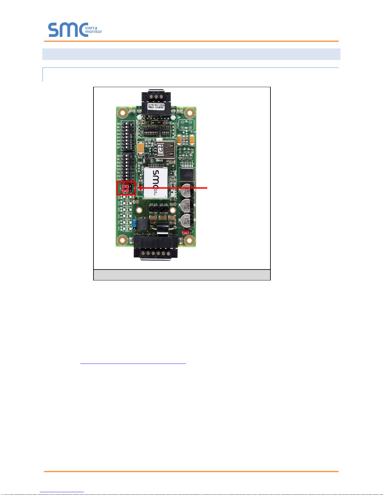
Bias Resistors
Figure 8: Bias Resistors
4.3 Resistor and Power Jumper Information
4.3.1 Bias Resistors
The ProtoNode bias resistors are used to keep the RS-485 bus to a known state, when there is no
transmission on the line (bus is idling), to help prevent false bits of data from being detected. The bias
resistors typically pull one line high and the other low - i.e. far away from the decision point of the logic.
In the RS-485 carrier, the bias resistor is 510 ohms which is in line with the BACnet spec. It should only
be enabled at one point on the bus (on the Brian field port were there are very weak bias resistors of
100k). Since there are no jumpers, many Brains can be put on network without running into the bias
resistor limit which is < 500 ohms.
NOTE: See www.ni.com/support/serial/resinfo.htm for additional pictures and notes.
Page 12 of 37

ProtoNode Start-Up Guide
Termination Resistor
Figure 9: Termination Resistor
4.3.2 Termination Resistor
Termination resistors are also used to reduce noise. These pull the two lines of an idle bus together.
However, they would override the effect of any bias resistors, if connected.
Page 13 of 37

ProtoNode Start-Up Guide
Power Jumper Switch
in position “A”
Figure 10: Power Jumper Switch
4.3.3 Power Jumper Settings
The ProtoNode Carrier Board power jumper is set to position A by default, but can be changed to position
B for other power supply requirements.
Position A: The Carrier makes use of a full-wave rectifying bridge. Can be used for 12-24 VAC input or
9 – 30 VDC input. At 9 VDC this becomes marginal.
Position B: The Carrier makes use of a half-wave rectifying bridge. Best position for Grounded AC
Transformers and for using DC voltage down to 9VDC.
Page 14 of 37

ProtoNode Start-Up Guide
BMS RS-
485 Wiring
ProtoNode
Pin #
Pin
Assignment
RS-485 +
Pin 1
RS-485 +
RS-485 -
Pin 2
RS-485 -
-
Pin 3
RS-485 GND
Figure 12: RS-485 BMS Network EOL Switch
Figure 11: Connection from ProtoNode to RS-485 Field Network
Figure 13: LonWorks Terminal
G
-
End-of-Line Switch
4.4 Wiring Field Port to RS-485 BMS Network
Connect the RS-485 network wires to the 3-pin RS-485 connector on ProtoNode FPC-N34 as
shown below in Figure 11.
o The RS-485 GND (Pin 3) is not typically connected
If the ProtoNode is the last device on the RS-485 trunk, then the End-Of-Line Termination
Switch needs to be enabled (Figure 12).
o The default setting from the factory is OFF (switch position = right side)
o To enable the EOL Termination, turn the EOL switch ON (switch position = left
side)
4.5 Wiring Field Port to a LonWorks Network
Connect ProtoNode to the field network with the LonWorks terminal using approved cable per the
FT-10 installation guidelines. LonWorks has no polarity.
Page 15 of 37

ProtoNode Start-Up Guide
Power Requirement for ProtoNode External Gateway
Current Draw Type
ProtoNode Family
12VDC/VAC
24VDC/VAC
30VDC
FPC – N34, N36, N38 (Typical)
170mA
100mA
80mA
FPC – N34, N36, N38 (Maximum)
240mA
140mA
100mA
FPC – N35, N37, N39 (Typical)
210mA
130mA
90mA
FPC – N35, N37, N39 (Maximum)
250mA
170mA
110mA
FPC – N40 (Typical)
170mA
100mA
80mA
FPC – N40 (Maximum)
240mA
140mA
100mA
FPC – N42 Slave (Maximum)
550mA
280mA
220mA
FPC – N42 Master (Maximum)
980mA
510mA
400mA
Note: These values are ‘nominal’ and a safety margin should be added to the power supply of the host
system. A safety margin of 25% is recommended.
Figure 14: Required current draw for the ProtoNode
Power to
ProtoNode
ProtoNode
Pin #
Pin
Assignment
Power In (+)
Pin 4
V +
Power In (-)
Pin 5
V -
Frame Ground
Pin 6
FRAME GND
Figure 15: Power Connections
4.6 Power-Up ProtoNode
Apply power to ProtoNode as show below in Figure 15. Ensure that the power supply used
complies with the specifications provided in Appendix C.1.
ProtoNode accepts either 9-30VDC or 12-24 VAC on pins 4 and 5.
Frame GND should be connected.
Page 16 of 37

ProtoNode Start-Up Guide
5 CONNECT THE PROTONODE’S W EB G UI TO SETUP IP ADDRESS FOR
ETHERNET NETWORK
5.1 Connect the PC to ProtoNode via the Ethernet Port
Connect a CAT5 Ethernet cable (Straight through or Cross-Over) between the PC and
ProtoNode.
The Default IP Address of ProtoNode is 192.168.1.24, Subnet Mask is 255.255.255.0. If the PC
and ProtoNode are on different IP Networks, assign a static IP Address to the PC on the
192.168.1.xxx network.
For Windows XP:
Go to > >
Right-click on Local Area Connection > Properties
Highlight >
For Windows 7 or later:
Go to > >
> >
Right-click on Local Area Connection > Properties
Highlight >
For Windows XP and Windows 7, use the following IP Address:
Click twice.
Page 17 of 37

ProtoNode Start-Up Guide
Figure 16: Web Configurator screen with Active Profiles
5.2 Setting IP Address for Field Network
After setting a local PC to be on the same subnet as the ProtoNode (Section 5.1), open a web
browser on the PC and enter the IP Address of the ProtoNode; the default address is
192.168.1.24.
The Web Configurator will be displayed as the landing page. (Figure 16)
NOTE: Below the “Active Profiles” heading are listed the profiles for connected devices. If no profiles are
present, then the wiring, baud rate, and DIP switch settings must be checked, because there is a
problem with device communications. All the active profiles must show the correct Node-ID’s
before proceeding.
NOTE: If multiple devices are connected to the ProtoNode and virtual server nodes are required,
set the BACnet Virtual Server Nodes field to “Yes”; otherwise leave the field on the default
“No” setting.
To access the Web GUI, click on the “Diagnostics & Debugging” button in the bottom right
side of the page.
Page 18 of 37

ProtoNode Start-Up Guide
Figure 17: Changing IP Address via Web GUI
From the Web GUI’s landing page, click on “Setup” to expand the navigation tree and then select
“Network Settings” to access the IP Settings menu. (Figure 17)
Modify the IP Address (N1 IP Address field) of the ProtoNode Ethernet port.
If necessary, change the Netmask (N1 Netmask field).
Type in a new Subnet Mask.
If necessary, change the IP Gateway (Default Gateway field).
Type in a new IP Gateway.
NOTE: If the ProtoNode is connected to a router, the IP Gateway of the ProtoNode should be set to the
IP Address as the router.
Reset ProtoNode.
Unplug Ethernet cable from PC and connect it to the network hub or router.
Record the IP Address assigned to the ProtoNode for future reference.
Page 19 of 37

ProtoNode Start-Up Guide
Figure 18: LonWorks Service Pin Location
6 LONWORKS (FPC-N35): COMMISSIONING PROTONODE ON A LONWORKS
NETWORK
Commissioning may only be performed by the LonWorks administrator.
6.1 Commissioning ProtoNode FPC-N35 on a LonWorks Network
The User will be prompted by the LonWorks Administrator to hit the Service Pin on the ProtoNode
FPC-N35 at the correct step of the Commissioning process which is different for each LonWorks
Network Management Tool.
If an XIF file is required, see steps in Section 6.1.1 to generate XIF.
6.1.1 Instructions to Download XIF File from ProtoNode FPC-N35 Using Browser
Connect a CAT5 Ethernet cable (Straight through or Cross-Over) between the PC and
ProtoNode.
The Default IP Address of ProtoNode is 192.168.1.24, Subnet Mask is 255.255.255.0. If the PC
and ProtoNode are on different IP Networks, assign a static IP Address to the PC on the
192.168.1.xxx network.
For Windows XP:
Go to > >
Right-click on Local Area Connection > Properties
Highlight >
For Windows 7 or later:
Go to > >
> >
Right-click on Local Area Connection > Properties
Highlight >
Page 20 of 37

ProtoNode Start-Up Guide
Figure 19: Sample of Fserver.XIF File Being Generated
For Windows XP and Windows 7, use the following IP Address:
Click twice.
Open a web browser and go to the following address: [IP Address of ProtoNode]/fserver.xif
o Example: 192.168.1.24/fserver.xif
If the web browser prompts to save the file, save the file onto the PC. If the web browser displays
the xif file as a web page, save the file on the local PC as “fserver.xif”.
Page 21 of 37

ProtoNode Start-Up Guide
Ethernet Port
Figure 20: Ethernet Port Location
Appendix A. Troubleshooting
Appendix A.1. Lost or Incorrect IP Address
Ensure that FieldServer Toolbox is Loaded on the PC that is currently being used, or download
FieldServer-Toolbox.zip on the Sierra Monitor webpage, under Customer Care: Resource Center,
Software Downloads:
www.sierramonitor.com/customer-care/resource-center?filters=software-downloads
Extract the executable file and complete the installation.
Disable any wireless Ethernet adapters on the PC/Laptop.
Disable firewall and virus protection software if possible.
Connect a standard CAT5 Ethernet cable between the PC and ProtoNode.
Double click on the FS Toolbox Utility.
Check IP Addresses from the Device listings.
Correct IP Address(es) by right clicking the settings icon and changing the IP Address.
Page 22 of 37

ProtoNode Start-Up Guide
Figure 21: Error messages screen
Appendix A.2. Viewing Diagnostic information
Type the IP Address of the ProtoNode into the local PC’s web browser or use the FieldServer
Toolbox to connect to the ProtoNode.
Click on Diagnostics and Debugging Button, then click on view, and then on connections.
If there are any errors showing on the Connection page, please refer to Appendix A.3 for the
relevant wiring and settings.
Page 23 of 37

ProtoNode Start-Up Guide
Appendix A.3. Check Wiring and Settings
No COMS on Modbus RTU side. If Tx/Rx are not flashing rapidly then there is a COM issue on
the Modbus side. To fix this problem, check the following:
o Visual observations of LEDs on ProtoNode. (Appendix A.4)
o Check baud rate, parity, data bits, stop bits
o Check Modbus device address
o Verify wiring
o Verify Modbus device is connected to the same subnet as the ProtoNode
o Verify all the Modbus devices were discovered in Web Configurator. (Section 5.2)
No COMS on Modbus TCP/IP side. To fix, check the following:
o Visual observations of LEDs on ProtoNode (Appendix A.4)
o Check device address
o Verify wiring
o Verify device is connected to the same subnet as the ProtoNode
o Verify all the Modbus TCP/IP devices were discovered in Web Configurator (Section 5.2)
Field COM problems:
o If Ethernet protocols are used, observe Ethernet LEDs on the ProtoNode (Appendix A.4)
o Visual dipswitch settings (using correct baud rate and device instance)
o Verify IP Address setting
o Verify wiring
If the problem still exists, a Diagnostic Capture needs to be taken and sent to Sierra Monitor
Corporation. (Appendix A.5)
Page 24 of 37

ProtoNode Start-Up Guide
Tag
Description
SPL
The SPL LED will light if the unit is not getting a response from one or more of the configured devices.
For LonWorks units, LED will light until the unit is commissioned on the LonWorks network.
RUN
The RUN LED will start flashing 20 seconds after power indicating normal operation.
ERR
The SYS ERR LED will go on solid 15 seconds after power up. It will turn off after 5 seconds. A steady
red light will indicate there is a system error on the unit. If this occurs, immediately report the related
“system error” shown in the error screen of the GUI interface to support for evaluation.
RX
If socket protocol is serial, the RX LED will flash when a message is received on the host port.
If socket protocol is Ethernet, this LED is not used.
TX
If socket protocol is serial, the TX LED will flash when a message is sent on the host port.
If socket protocol is Ethernet, this LED is not used.
PWR
This is the power light and should show steady green at all times when the unit is powered.
Figure 22: Diagnostic LEDs
Diagnostic LEDs
Appendix A.4. LED Diagnostics for Communications Between ProtoNode and Devices
Please see the diagram below for ProtoNode FPC-N34 and FPC-N35 LED Locations.
Page 25 of 37

ProtoNode Start-Up Guide
Ethernet Port
Figure 23: Ethernet Port Location
Appendix A.5. Take Diagnostic Capture With the FieldServer Toolbox
Once the Diagnostic Capture is complete, email it to support@sierramonitor.com. The
Diagnostic Capture will allow us to rapidly diagnose the problem.
Ensure that FieldServer Toolbox is Loaded on the PC that is currently being used, or download
FieldServer-Toolbox.zip on the Sierra Monitor Corporation webpage, under Customer Care:
Resource Center, Software Downloads:
www.sierramonitor.com/customer-care/resource-center?filters=software-downloads
Extract the executable file and complete the installation.
Disable any wireless Ethernet adapters on the PC/Laptop.
Disable firewall and virus protection software if possible.
Connect a standard CAT5 Ethernet cable between the PC and ProtoNode .
Double click on the FS Toolbox Utility.
Step 1: Take a Log
o Click on the diagnose icon of the desired device
Page 26 of 37

ProtoNode Start-Up Guide
o Select full Diagnostic
NOTE: If desired, the default capture period can be changed.
o Click on Start Diagnostic
o Wait for Capture period to finish, then the Diagnostic Test Complete window will appear
Page 27 of 37

ProtoNode Start-Up Guide
Step 2: Send Log
o Once the Diagnostic test is complete, a .zip file will be saved on the PC
o Choose Open to launch explorer and have it point directly at the correct folder
o Send the Diagnostic zip file to support@sierramonitor.com
Page 28 of 37

ProtoNode Start-Up Guide
Figure 24: Web Configurator – Setting Network Number for BACnet
Appendix A.6. Update Firmware
To load a new version of the firmware, follow these instructions:
1. Extract and save the new file onto the local PC.
2. Open a web browser and type the IP Address of the FieldServer in the address bar.
NOTE: Default IP Address is 192.168.1.24
NOTE: Use the FS Toolbox utility if the IP Address is unknown (Appendix A.1)
3. Click on the “Diagnostics & Debugging” button.
4. In the Navigation Tree on the left hand side, do the following:
a. Click on “Setup”
b. Click on “File Transfer”
c. Click on the “Firmware” tab
5. In the Firmware tab, click on “Choose Files” and select the firmware file extracted in step 1.
6. Click on the orange “Submit” button.
7. When the download is complete, click on the “System Restart” button.
Appendix A.7. BACnet: Setting Network_Number for more than one ProtoNode on Subnet
For both BACnet MS/TP and BACnet/IP, if more than one ProtoNode is connected to the same subnet,
they must be assigned unique Network_Number values.
On the main Web Configuration screen, update the Network Number with the “network_nr” field and click
submit. The default value is 50.
Page 29 of 37

ProtoNode Start-Up Guide
Appendix A.8. Passwords
Access to the ProtoNode can be restricted by enabling a password. There are 2 access levels defined by
2 account names: Admin and User.
The Admin account has unrestricted access to the ProtoNode.
The User account can view any ProtoNode information, but cannot make any changes or restart
the ProtoNode.
The password needs to be a minimum of eight characters and is case sensitive.
If the password is lost, click cancel on the password authentication popup window, and e-mail the
Password recovery token to support@sierramonitor.com to receive a temporary password from the Sierra
Monitor support team. Access the ProtoNode to set a new password.
Appendix A.9. Reading Data Arrays
Connect to the ProtoNode with a browser and click on the Diagnostics & Debugging button.
Select the User Messages branch.
Select the info tab.
See which profile has been loaded.
o Example: prof1b.csv
In the address bar of the browser, type the IP address/filename.
o Example: 192.168.1.24/prof1b.csv
Press the enter key and save the file.
Open the file and go to the server side map descriptors section.
The map_descriptor_name, data_array_name, and data array_offset will be shown for each point.
Go back to the browser and select the view branch.
Select the data arrays branch.
Select the data array that corresponds with the point that you want to monitor.
View the offset that corresponds with the point that you want to monitor.
Page 30 of 37

ProtoNode Start-Up Guide
S Bank DIP Switches
A1, A2, and A3 DIP Switches
Figure 25: Additional DIP Switches
Appendix B. Vendor Information
Appendix B.1. Additional DIP switch settings
When more configuration settings are needed than possible via the external S Bank DIP Switches, then
the user can access the A Bank DIP Switches internal to the ProtoNode.
NOTE: The lid on top of the ProtoNode has to be removed in order to select the A Bank of DIP switches.
Pull on the lid while holding the on to the 6 pin Phoenix connector. Please do not hold the wall
mount tabs as these are designed to break off if not required!
To set select these configurations, open the ProtoNode and select the A bank of switches (A1 or
A2 or A3) on the small ProtoCessor module that sits on top of the ProtoCarrier (inside the
ProtoNode).
Page 31 of 37

ProtoNode Start-Up Guide
ProtoNode FPC-N34/-N36/-N38
ProtoNode FPC-N35/-N37/-N39
Electrical Connections
One 6-pin Phoenix connector with:
RS-485 port (+ / - / gnd)
Power port (+ / - / Frame-gnd)
One 3-pin Phoenix connector with:
RS-485 port (+ / - / gnd)
One Ethernet 10/100 BaseT port
One 6-pin Phoenix connector with:
RS-485 port (+ / - / gnd)
Power port (+ / - / Frame-gnd)
One Ethernet 10/100 BaseT port
One FTT-10 LonWorks port
Approvals
CE Certified; TUV approved to UL 916, EN 60950-1,
EN 50491-3 and CSA C22-2 standards; FCC Class A Part 15;
DNP3 Conformance Tested; RoHS Compliant; CSA 205 Approved
BTL Marked
LonMark Certified
Power Requirements
Multi-mode power adapter: 9-30VDC or 12 - 24VAC
Physical Dimensions
11.5 cm L x 8.3 cm W x 4.1 cm H (4.5 x 3.2 x 1.6 in.)
Weight
0.2 kg (0.4 lbs)
Operating Temperature
-40°C to 75°C (-40°F to167°F)
Surge Suppression
EN61000-4-2 ESD EN61000-4-3 EMC EN61000-4-4 EFT
Humidity
5 - 90% RH (non-condensing)
(Specifications subject to change without notice)
Figure 26: Specifications
Interface Connections
RS-2321
RS-4852
RS-4223
Ethernet4
LonWorks5
KNX6
M-Bus7
ProtoNode
FPC-N34
2 1
FPC-N35
1 1 1
FPC-N36
1 1 1
FPC-N37
1 1 1
FPC-N38
1 1 1
FPC-N39
1 1 1
FPC-N40
1 1
1
FPC-N41
1 1
1
FPC-N42
1 1
1
1 Tx/Rx/GND
2 +/-/Frame Ground
3 +/-/Frame Ground
4 10/100 BaseT
5 FTT 10
6 +/-/Frame Ground
7 +/-/Frame Ground
Appendix C. Reference
Appendix C.1. Specifications
Page 32 of 37

ProtoNode Start-Up Guide
Appendix C.1.1. Compliance with UL Regulations
For UL compliance, the following instructions must be met when operating ProtoNode.
The units shall be powered by listed LPS or Class 2 power supply suited to the expected
operating temperature range.
The interconnecting power connector and power cable shall:
o Comply with local electrical code.
o Be suited to the expected operating temperature range.
o Meet the current and voltage rating for ProtoNode
Furthermore, the interconnecting power cable shall:
o Be of length not exceeding 3.05m (118.3”)
o Be constructed of materials rated VW-1 or FT-1 or better
If the unit is to be installed in an operating environment with a temperature above 65 °C, it should
be installed in a Restricted Access Area requiring a key or a special tool to gain access.
This device must not be connected to a LAN segment with outdoor wiring.
Page 33 of 37

ProtoNode Start-Up Guide
Address
A0
A1
A2
A3
A4
A5
A6
A7
1
On
Off
Off
Off
Off
Off
Off
Off 2 Off
On
Off
Off
Off
Off
Off
Off 3 On
On
Off
Off
Off
Off
Off
Off 4 Off
Off
On
Off
Off
Off
Off
Off 5 On
Off
On
Off
Off
Off
Off
Off 6 Off
On
On
Off
Off
Off
Off
Off 7 On
On
On
Off
Off
Off
Off
Off 8 Off
Off
Off
On
Off
Off
Off
Off 9 On
Off
Off
On
Off
Off
Off
Off
10
Off
On
Off
On
Off
Off
Off
Off
11
On
On
Off
On
Off
Off
Off
Off
12
Off
Off
On
On
Off
Off
Off
Off
13
On
Off
On
On
Off
Off
Off
Off
14
Off
On
On
On
Off
Off
Off
Off
15
On
On
On
On
Off
Off
Off
Off
16
Off
Off
Off
Off
On
Off
Off
Off
17
On
Off
Off
Off
On
Off
Off
Off
18
Off
On
Off
Off
On
Off
Off
Off
19
On
On
Off
Off
On
Off
Off
Off
20
Off
Off
On
Off
On
Off
Off
Off
21
On
Off
On
Off
On
Off
Off
Off
22
Off
On
On
Off
On
Off
Off
Off
23
On
On
On
Off
On
Off
Off
Off
24
Off
Off
Off
On
On
Off
Off
Off
25
On
Off
Off
On
On
Off
Off
Off
26
Off
On
Off
On
On
Off
Off
Off
27
On
On
Off
On
On
Off
Off
Off
28
Off
Off
On
On
On
Off
Off
Off
29
On
Off
On
On
On
Off
Off
Off
30
Off
On
On
On
On
Off
Off
Off
31
On
On
On
On
On
Off
Off
Off
32
Off
Off
Off
Off
Off
On
Off
Off
33
On
Off
Off
Off
Off
On
Off
Off
34
Off
On
Off
Off
Off
On
Off
Off
35
On
On
Off
Off
Off
On
Off
Off
36
Off
Off
On
Off
Off
On
Off
Off
37
On
Off
On
Off
Off
On
Off
Off
38
Off
On
On
Off
Off
On
Off
Off
39
On
On
On
Off
Off
On
Off
Off
40
Off
Off
Off
On
Off
On
Off
Off
41
On
Off
Off
On
Off
On
Off
Off
42
Off
On
Off
On
Off
On
Off
Off
43
On
On
Off
On
Off
On
Off
Off
44
Off
Off
On
On
Off
On
Off
Off
45
On
Off
On
On
Off
On
Off
Off
Address
A0
A1
A2
A3
A4
A5
A6
A7
46
Off
On
On
On
Off
On
Off
Off
47
On
On
On
On
Off
On
Off
Off
48
Off
Off
Off
Off
On
On
Off
Off
49
On
Off
Off
Off
On
On
Off
Off
50
Off
On
Off
Off
On
On
Off
Off
51
On
On
Off
Off
On
On
Off
Off
52
Off
Off
On
Off
On
On
Off
Off
53
On
Off
On
Off
On
On
Off
Off
54
Off
On
On
Off
On
On
Off
Off
55
On
On
On
Off
On
On
Off
Off
56
Off
Off
Off
On
On
On
Off
Off
57
On
Off
Off
On
On
On
Off
Off
58
Off
On
Off
On
On
On
Off
Off
59
On
On
Off
On
On
On
Off
Off
60
Off
Off
On
On
On
On
Off
Off
61
On
Off
On
On
On
On
Off
Off
62
Off
On
On
On
On
On
Off
Off
63
On
On
On
On
On
On
Off
Off
64
Off
Off
Off
Off
Off
Off
On
Off
65
On
Off
Off
Off
Off
Off
On
Off
66
Off
On
Off
Off
Off
Off
On
Off
67
On
On
Off
Off
Off
Off
On
Off
68
Off
Off
On
Off
Off
Off
On
Off
69
On
Off
On
Off
Off
Off
On
Off
70
Off
On
On
Off
Off
Off
On
Off
71
On
On
On
Off
Off
Off
On
Off
72
Off
Off
Off
On
Off
Off
On
Off
73
On
Off
Off
On
Off
Off
On
Off
74
Off
On
Off
On
Off
Off
On
Off
75
On
On
Off
On
Off
Off
On
Off
76
Off
Off
On
On
Off
Off
On
Off
77
On
Off
On
On
Off
Off
On
Off
78
Off
On
On
On
Off
Off
On
Off
79
On
On
On
On
Off
Off
On
Off
80
Off
Off
Off
Off
On
Off
On
Off
81
On
Off
Off
Off
On
Off
On
Off
82
Off
On
Off
Off
On
Off
On
Off
83
On
On
Off
Off
On
Off
On
Off
84
Off
Off
On
Off
On
Off
On
Off
85
On
Off
On
Off
On
Off
On
Off
86
Off
On
On
Off
On
Off
On
Off
87
On
On
On
Off
On
Off
On
Off
88
Off
Off
Off
On
On
Off
On
Off
89
On
Off
Off
On
On
Off
On
Off
90
Off
On
Off
On
On
Off
On
Off
Appendix D. Bank DIP Switch Settings
Appendix D.1. “A” Bank DIP Switch Settings
Page 34 of 37

ProtoNode Start-Up Guide
Address
A0
A1
A2
A3
A4
A5
A6
A7
91
On
On
Off
On
On
Off
On
Off
92
Off
Off
On
On
On
Off
On
Off
93
On
Off
On
On
On
Off
On
Off
94
Off
On
On
On
On
Off
On
Off
95
On
On
On
On
On
Off
On
Off
96
Off
Off
Off
Off
Off
On
On
Off
97
On
Off
Off
Off
Off
On
On
Off
98
Off
On
Off
Off
Off
On
On
Off
99
On
On
Off
Off
Off
On
On
Off
100
Off
Off
On
Off
Off
On
On
Off
101
On
Off
On
Off
Off
On
On
Off
102
Off
On
On
Off
Off
On
On
Off
103
On
On
On
Off
Off
On
On
Off
104
Off
Off
Off
On
Off
On
On
Off
105
On
Off
Off
On
Off
On
On
Off
106
Off
On
Off
On
Off
On
On
Off
107
On
On
Off
On
Off
On
On
Off
108
Off
Off
On
On
Off
On
On
Off
109
On
Off
On
On
Off
On
On
Off
110
Off
On
On
On
Off
On
On
Off
111
On
On
On
On
Off
On
On
Off
112
Off
Off
Off
Off
On
On
On
Off
113
On
Off
Off
Off
On
On
On
Off
114
Off
On
Off
Off
On
On
On
Off
115
On
On
Off
Off
On
On
On
Off
116
Off
Off
On
Off
On
On
On
Off
117
On
Off
On
Off
On
On
On
Off
118
Off
On
On
Off
On
On
On
Off
119
On
On
On
Off
On
On
On
Off
120
Off
Off
Off
On
On
On
On
Off
121
On
Off
Off
On
On
On
On
Off
122
Off
On
Off
On
On
On
On
Off
123
On
On
Off
On
On
On
On
Off
124
Off
Off
On
On
On
On
On
Off
125
On
Off
On
On
On
On
On
Off
126
Off
On
On
On
On
On
On
Off
127
On
On
On
On
On
On
On
Off
128
Off
Off
Off
Off
Off
Off
Off
On
129
On
Off
Off
Off
Off
Off
Off
On
130
Off
On
Off
Off
Off
Off
Off
On
131
On
On
Off
Off
Off
Off
Off
On
132
Off
Off
On
Off
Off
Off
Off
On
133
On
Off
On
Off
Off
Off
Off
On
134
Off
On
On
Off
Off
Off
Off
On
135
On
On
On
Off
Off
Off
Off
On
136
Off
Off
Off
On
Off
Off
Off
On
137
On
Off
Off
On
Off
Off
Off
On
138
Off
On
Off
On
Off
Off
Off
On
Address
A0
A1
A2
A3
A4
A5
A6
A7
139
On
On
Off
On
Off
Off
Off
On
140
Off
Off
On
On
Off
Off
Off
On
141
On
Off
On
On
Off
Off
Off
On
142
Off
On
On
On
Off
Off
Off
On
143
On
On
On
On
Off
Off
Off
On
144
Off
Off
Off
Off
On
Off
Off
On
145
On
Off
Off
Off
On
Off
Off
On
146
Off
On
Off
Off
On
Off
Off
On
147
On
On
Off
Off
On
Off
Off
On
148
Off
Off
On
Off
On
Off
Off
On
149
On
Off
On
Off
On
Off
Off
On
150
Off
On
On
Off
On
Off
Off
On
151
On
On
On
Off
On
Off
Off
On
152
Off
Off
Off
On
On
Off
Off
On
153
On
Off
Off
On
On
Off
Off
On
154
Off
On
Off
On
On
Off
Off
On
155
On
On
Off
On
On
Off
Off
On
156
Off
Off
On
On
On
Off
Off
On
157
On
Off
On
On
On
Off
Off
On
158
Off
On
On
On
On
Off
Off
On
159
On
On
On
On
On
Off
Off
On
160
Off
Off
Off
Off
Off
On
Off
On
161
On
Off
Off
Off
Off
On
Off
On
162
Off
On
Off
Off
Off
On
Off
On
163
On
On
Off
Off
Off
On
Off
On
164
Off
Off
On
Off
Off
On
Off
On
165
On
Off
On
Off
Off
On
Off
On
166
Off
On
On
Off
Off
On
Off
On
167
On
On
On
Off
Off
On
Off
On
168
Off
Off
Off
On
Off
On
Off
On
169
On
Off
Off
On
Off
On
Off
On
170
Off
On
Off
On
Off
On
Off
On
171
On
On
Off
On
Off
On
Off
On
172
Off
Off
On
On
Off
On
Off
On
173
On
Off
On
On
Off
On
Off
On
174
Off
On
On
On
Off
On
Off
On
175
On
On
On
On
Off
On
Off
On
176
Off
Off
Off
Off
On
On
Off
On
177
On
Off
Off
Off
On
On
Off
On
178
Off
On
Off
Off
On
On
Off
On
179
On
On
Off
Off
On
On
Off
On
180
Off
Off
On
Off
On
On
Off
On
181
On
Off
On
Off
On
On
Off
On
182
Off
On
On
Off
On
On
Off
On
183
On
On
On
Off
On
On
Off
On
184
Off
Off
Off
On
On
On
Off
On
185
On
Off
Off
On
On
On
Off
On
186
Off
On
Off
On
On
On
Off
On
Page 35 of 37

ProtoNode Start-Up Guide
Address
A0
A1
A2
A3
A4
A5
A6
A7
187
On
On
Off
On
On
On
Off
On
188
Off
Off
On
On
On
On
Off
On
189
On
Off
On
On
On
On
Off
On
190
Off
On
On
On
On
On
Off
On
191
On
On
On
On
On
On
Off
On
192
Off
Off
Off
Off
Off
Off
On
On
193
On
Off
Off
Off
Off
Off
On
On
194
Off
On
Off
Off
Off
Off
On
On
195
On
On
Off
Off
Off
Off
On
On
196
Off
Off
On
Off
Off
Off
On
On
197
On
Off
On
Off
Off
Off
On
On
198
Off
On
On
Off
Off
Off
On
On
199
On
On
On
Off
Off
Off
On
On
200
Off
Off
Off
On
Off
Off
On
On
201
On
Off
Off
On
Off
Off
On
On
202
Off
On
Off
On
Off
Off
On
On
203
On
On
Off
On
Off
Off
On
On
204
Off
Off
On
On
Off
Off
On
On
205
On
Off
On
On
Off
Off
On
On
206
Off
On
On
On
Off
Off
On
On
207
On
On
On
On
Off
Off
On
On
208
Off
Off
Off
Off
On
Off
On
On
209
On
Off
Off
Off
On
Off
On
On
210
Off
On
Off
Off
On
Off
On
On
211
On
On
Off
Off
On
Off
On
On
212
Off
Off
On
Off
On
Off
On
On
213
On
Off
On
Off
On
Off
On
On
214
Off
On
On
Off
On
Off
On
On
215
On
On
On
Off
On
Off
On
On
216
Off
Off
Off
On
On
Off
On
On
217
On
Off
Off
On
On
Off
On
On
218
Off
On
Off
On
On
Off
On
On
219
On
On
Off
On
On
Off
On
On
220
Off
Off
On
On
On
Off
On
On
221
On
Off
On
On
On
Off
On
On
222
Off
On
On
On
On
Off
On
On
223
On
On
On
On
On
Off
On
On
224
Off
Off
Off
Off
Off
On
On
On
225
On
Off
Off
Off
Off
On
On
On
226
Off
On
Off
Off
Off
On
On
On
227
On
On
Off
Off
Off
On
On
On
228
Off
Off
On
Off
Off
On
On
On
229
On
Off
On
Off
Off
On
On
On
230
Off
On
On
Off
Off
On
On
On
231
On
On
On
Off
Off
On
On
On
232
Off
Off
Off
On
Off
On
On
On
233
On
Off
Off
On
Off
On
On
On
234
Off
On
Off
On
Off
On
On
On
Address
A0
A1
A2
A3
A4
A5
A6
A7
235
On
On
Off
On
Off
On
On
On
236
Off
Off
On
On
Off
On
On
On
237
On
Off
On
On
Off
On
On
On
238
Off
On
On
On
Off
On
On
On
239
On
On
On
On
Off
On
On
On
240
Off
Off
Off
Off
On
On
On
On
241
On
Off
Off
Off
On
On
On
On
242
Off
On
Off
Off
On
On
On
On
243
On
On
Off
Off
On
On
On
On
244
Off
Off
On
Off
On
On
On
On
245
On
Off
On
Off
On
On
On
On
246
Off
On
On
Off
On
On
On
On
247
On
On
On
Off
On
On
On
On
248
Off
Off
Off
On
On
On
On
On
249
On
Off
Off
On
On
On
On
On
250
Off
On
Off
On
On
On
On
On
251
On
On
Off
On
On
On
On
On
252
Off
Off
On
On
On
On
On
On
253
On
Off
On
On
On
On
On
On
254
Off
On
On
On
On
On
On
On
255
On
On
On
On
On
On
On
On
Page 36 of 37

ProtoNode Start-Up Guide
Appendix E. Limited 2 Year Warranty
Sierra Monitor Corporation warrants its products to be free from defects in workmanship or
material under normal use and service for two years after date of shipment. Sierra Monitor
Corporation will repair or replace any equipment found to be defective during the warranty
period. Final determination of the nature and responsibility for defective or damaged equipment
will be made by Sierra Monitor Corporation personnel.
All warranties hereunder are contingent upon proper use in the application for which the product
was intended and do not cover products which have been modified or repaired without Sierra
Monitor Corporation’s approval or which have been subjected to accident, improper
maintenance, installation or application, or on which original identification marks have been
removed or altered. This Limited Warranty also will not apply to interconnecting cables or wires,
consumables or to any damage resulting from battery leakage.
In all cases Sierra Monitor Corporation’s responsibility and liability under this warranty shall be
limited to the cost of the equipment. The purchaser must obtain shipping instructions for the
prepaid return of any item under this warranty provision and compliance with such instruction
shall be a condition of this warranty.
Except for the express warranty stated above, Sierra Monitor Corporation disclaims all
warranties with regard to the products sold hereunder including all implied warranties of
merchantability and fitness and the express warranties stated herein are in lieu of all obligations
or liabilities on the part of Sierra Monitor Corporation for damages including, but not limited to,
consequential damages arising out of/or in connection with the use or performance of the
product.
Page 37 of 37
 Loading...