


Driver Revision: 1.12
Document Revision: 4.B
APPLICABILITY & EFFECTIVITY
Effective for all systems manufactured after October 2016.
FieldServer
FS-8704-03 Modbus TCP/IP
Driver Manual
(Supplement to the FieldServer Instruction Manual)

Modbus TCP/IP Driver Manual
Technical Support
Please call us for any technical support needs related to the FieldServer product.
Sierra Monitor Corporation
1991 Tarob Court
Milpitas, CA 95035
Website: www.sierramonitor.com
U.S. Support Information:
+1 408 262-6611
+1 800 727-4377
Email: support@sierramonitor.com
EMEA Support Information:
+44 2033 1813 41
Email: support.emea@sierramonitor.com
Contact Information

Modbus TCP/IP Driver Manual
TABLE OF CONTENTS
1 Modbus TCP/IP Description ................................................................................................................ 4
2 Driver Scope of Supply ....................................................................................................................... 4
2.1 Supplied by Sierra Monitor for this driver ............................................................................ 4
2.2 Provided by the Supplier of 3rd Party Equipment ............................................................... 4
2.2.1 Hardware ............................................................................................................................... 4
3 Hardware Connections ........................................................................................................................ 5
4 Data Array Parameters ........................................................................................................................ 6
5 Configuring the FieldServer as a Modbus TCP/IP Client ................................................................. 7
5.1 Client Side Connection Parameters ............................................................................................... 7
5.2 Client Side Node Parameters ......................................................................................................... 8
5.3 Client Side Map Descriptor Parameters ......................................................................................... 9
5.3.1 FieldServer Specific Map Descriptor Parameters ................................................................... 9
5.3.2 Driver Specific Map Descriptor Parameters ............................................................................ 9
5.3.3 Timing Parameters ................................................................................................................ 10
5.3.4 Map Descriptor Examples ..................................................................................................... 11
6 Configuring the FieldServer as a Modbus TCP/IP Server ............................................................. 12
6.1 Server Side Connection Parameters ............................................................................................ 12
6.2 Server Side Node Parameters ...................................................................................................... 13
6.3 Server Side Map Descriptor Parameters ...................................................................................... 14
6.3.1 FieldServer Specific Map Descriptor Parameters ................................................................. 14
6.3.2 Driver Specific Map Descriptor Parameters .......................................................................... 14
6.3.3 Map Descriptor Examples ..................................................................................................... 15
6.3.4 Slave_ID ................................................................................................................................ 15
6.3.4.1 Slave_ID Lookup in Table .............................................................................................. 15
Appendix A. Useful Features ................................................................................................................... 16
Appendix A.1. Managing Floating Points with Modbus ........................................................................... 16
Appendix A.1.1. Transferring Non-integer Values with One Register ................................. 16
Appendix A.1.2. Transferring Float/32 bit Values with Two Registers................................ 16
Appendix A.2. Node_Offline_Response .................................................................................................. 17
Appendix A.3. Splitting Registers into Bytes or Bits ................................................................................ 18
Appendix A.4. Reading Device Identification .......................................................................................... 18
Appendix A.4.1. Client Side Map Descriptor ............................................................................. 18
Appendix A.4.2. Server Side Map Descriptor ............................................................................ 19
Appendix A.5. Broadcasting Write Messages ......................................................................................... 19
Appendix A.6. Reading Scattered Addresses ......................................................................................... 20
Appendix B. Troubleshooting .................................................................................................................. 21
Appendix B.1. Server Configuration of System Station Address ............................................................ 21
Appendix B.2. Modbus TCP/IP Connection Error Descriptions .............................................................. 21
Appendix B.3. Understanding Max Concurrent Messages ..................................................................... 21
Appendix C. Reference ............................................................................................................................. 23
Appendix C.1. Data Types ...................................................................................................................... 23
Appendix C.2. Single Writes .................................................................................................................... 23
Appendix C.3. Driver Error Messages ..................................................................................................... 23
Table of Contents

Modbus TCP/IP Driver Manual
PART #
Description
FS-8915-10
UTP cable (7 foot) for Ethernet connection1
Description
Modbus/TCP Server, e.g. Quantum PLC
2
Modbus/TCP Host Node [such as: Intellution Fix, Wondereware Intouch, GE Cimplicity, Quantum PLC
(Master)]
3
1
2
3
1 MODBUS TCP/IP DESCRIPTION
The Modbus TCP Driver allows the FieldServer to transfer data to and from devices over Ethernet using
the Modbus TCP/IP Protocol. The Modbus TCP/IP driver uses port 502, which is not configurable. The
driver was developed for Modbus Application Protocol Specification V1.1a from Modbus-IDA. The
specification can be found at www.modbus.org. The FieldServer can emulate either a Server or Client.
The information that follows describes how to expand upon the factory defaults provided in the
configuration files included with the FieldServer.
There are various register mapping models being followed by various vendors.
To cover all these mappings, FieldServer uses the following three Models:
Modicon_5digit – Use this format where addresses are defined in 0xxxx, 1xxxx, 3xxxx or 4xxxx
format. A maximum of 9999 registers can be mapped of each type. This is FieldServer driver’s
default format.
ADU – Application Data Unit address. Use this format where addresses of each type are defined
in the range 1-65536.
PDU – Protocol Data unit address. Use this format where addresses of each type are defined in
the range 0-65535.
An example of the key difference between ADU and PDU:
If Address_Type is ADU and address is 1, the driver will poll for register 0.
If Address_Type is PDU, the driver will poll for address 1.
NOTE: If the vendor document shows addresses in extended Modicon (i.e. 6 digit) format like
4xxxxx then consider these addresses as xxxxx (omit the first digit) and use either ADU or
PDU.
NOTE: The purpose of providing 3 different ways of addressing the Modbus registers is to allow
the user to choose the addressing system most compatible with the address list being
used. At the protocol level, the same protocol specification is used for all three with the
exception of the limited address range for Modicon_5digit.
2 DRIVER SCOPE OF SUPPLY
2.1 Supplied by Sierra Monitor for this driver
2.2 Provided by the Supplier of 3rd Party Equipment
2.2.1 Hardware
This cable is necessary for connection to the driver. It is shipped with the FieldServer and not separately with the driver.
If FieldServer is used as a Modbus/TCP Client.
If FieldServer is used as a Modbus/TCP Server.
Page 4 of 23
Modbus TCP/IP Driver Manual
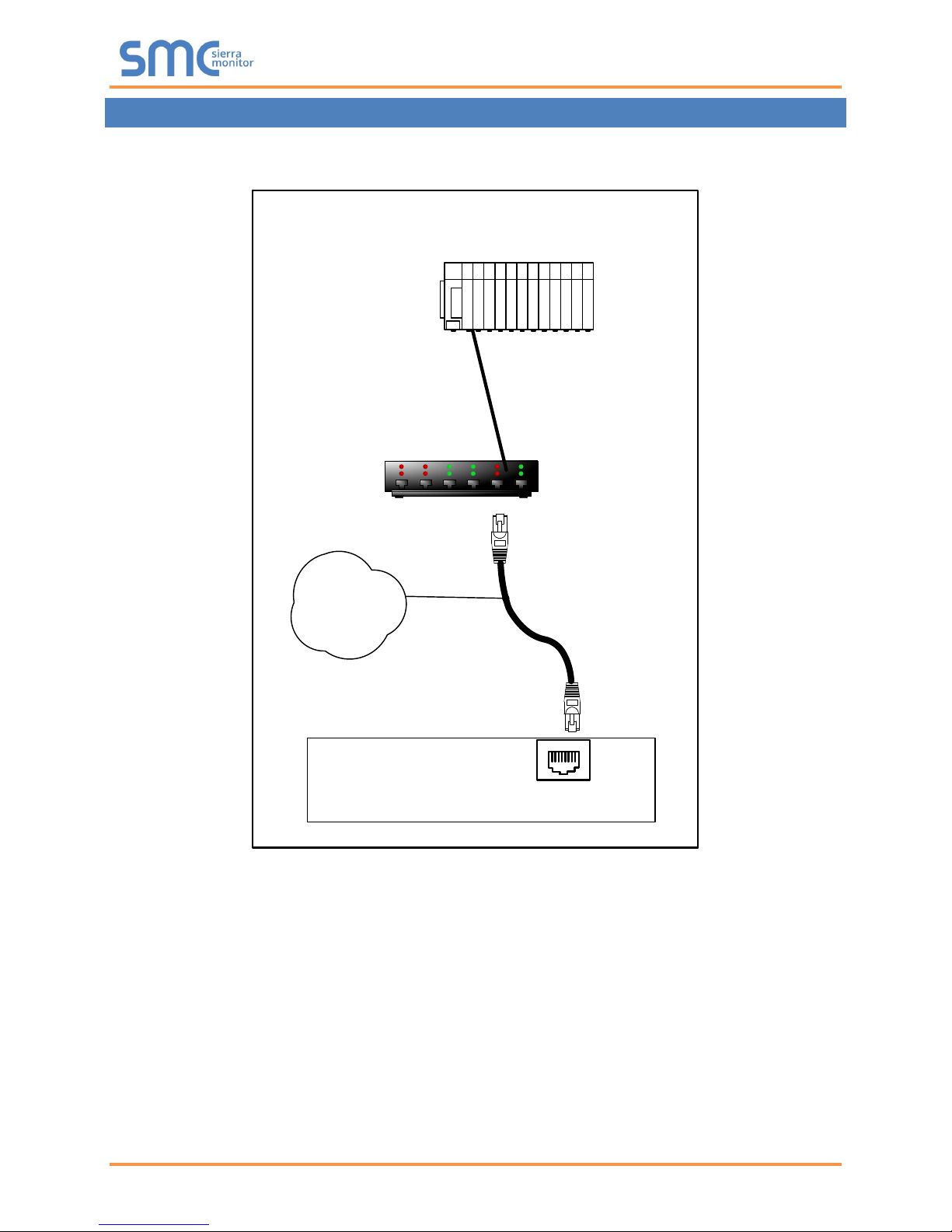
FieldServer
FieldServer Part #
8915-10
UTP cable
Connect to an Ethernet Port
on the FieldServer
N1
18
Switch
Remote Modbus
Device
3 HARDWARE CONNECTIONS
Configure the PLC according to manufacturer’s instructions.
Page 5 of 23

Modbus TCP/IP Driver Manual
Section Title
Data_Arrays
Column Title
Function
Legal Values
Data_Array_Name
Provide name for Data Array.
Up to 15 alphanumeric
characters
Data_Array_Format
Provide data format. Each Data Array can only
take on one format.
UINT 16, UINT 32, SINT 16,
SINT 32, BIT, FLOAT
Data_Array_Length
Number of Data Objects. Must be larger than the
data storage area required by the Map Descriptors
for the data being placed in this array.
1 – 255
// Data Arrays
Data_Arrays
Data_Array_Name
, Data_Array_Format
, Data_Array_Length
DA_AI_01
, Float
, 200
DA_AO_01
, Float
, 200
DA_DI_01
, Bit
, 200
DA_DO_01
, Bit
, 200
4 DATA ARRAY PARAMETERS
Data Arrays are “protocol neutral” data buffers for storage of data to be passed between protocols. It is
necessary to declare the data format of each of the Data Arrays to facilitate correct storage of the relevant
data.
Example
Page 6 of 23

Modbus TCP/IP Driver Manual
Section Title
Connections
Column Title
Function
Legal Values
Adapter
Specify which adapter this protocol uses.
N1
Protocol
Specify protocol used.
Modbus/TCP
Poll Delay*
Time interval between polls.
0-32000 s, 0.05 s
Max_Concurrent_Messages*4
Specify the maximum messages the driver
can send, before waiting for responses.
0 – 65534
(0 or 1 disables
concurrent messaging
meaning only 1 active
message at a time)
// Client Side Connections
Connections
Adapter
, Protocol
, Poll_Delay
N1
, Modbus/TCP
, 0.05s
4
5 CONFIGURING THE FIELDSERVER AS A MODBUS TCP/IP CLIENT
For detailed information on FieldServer configuration, refer to the FieldServer Configuration Manual. The
information that follows describes how to expand upon the factory defaults provided in the configuration
files included with the FieldServer (see “.csv” sample files provided with the FieldServer).
This section documents and describes the parameters necessary for configuring the FieldServer to
communicate with a Modbus TCP/IP Server.
The configuration file tells the FieldServer about its interfaces, and the routing of data required. In order to
enable the FieldServer for Modbus TCP/IP communications the following three actions must be taken.
The driver independent FieldServer buffers need to be declared in the “Data Arrays” section. The
destination device addresses need to be declared in the “Client Side Nodes” section. And the data
required from the server(s) needs to be mapped in the “Client Side Map Descriptors” section. Details on
how to perform these steps can be found in the following sections.
NOTE: In the following tables, * indicates an optional parameter with the bold legal value as the default.
5.1 Client Side Connection Parameters
Example
Using Max_Concurrent_Messages value > 1 could improve communication performance, but it also depends on the remote
Server’s implementation. The server might not support multiple messaging, so match this number with the Server's capability.
Page 7 of 23

Modbus TCP/IP Driver Manual
Section Title
Nodes
Column Title
Function
Legal Values
Node_Name
Provide name for node.
Up to 32 alphanumeric
characters
Node_ID
Station Address of Remote Server Node.
0 – 255
Protocol
Specify protocol used.
Modbus/TCP
Adapter
Specify which adapter this protocol uses.
N1
IP_address
IP address of client PLC.
Valid IP address (for
example - 192.168.1.13)
Address_Type5
Specify Register Mapping Model.
ADU,PDU,
Modicon_5digit
Modbus_TCP_
IP_Port*
Select remote Internet Protocol Port.
1-65534, 502
Write_Fnc*
Set to Multiple if Remote Server Node only supports Write
Multiple function code 15 & 16.
Multiple, -
Write_Length*
Set to MD_Length if write-thru operation should write all
registers as specified by MD_Length.
By default write-thru writes a single register.
If Write_Length also specified on Map Descriptor, Map
Descriptor’s parameter will be used.
MD_Length, -, 1
// Client Side Nodes for new devices where 65536 registers are available in each memory area
Nodes
Node_Name
, Node_ID
, Protocol
, Adapter
, Address_Type
, IP_Address
Modbus device 1
, 1
, Modbus/TCP
, N1
, ADU
, 192.168.1.172
// Client Side Nodes for devices where only 9999 registers are available in each memory area
Nodes
Node_Name
, Node_ID
, Protocol
, Adapter
, IP_Address
Modbus device 3
, 3
, Modbus/TCP
, N1
, 192.168.1.172
5
5.2 Client Side Node Parameters
Example
Optional for Modicon 5 digit devices.
Page 8 of 23

Modbus TCP/IP Driver Manual
Column Title
Function
Legal Values
Map_Descriptor_Name
Name of this Map Descriptor.
Up to 32 alphanumeric characters
Data_Array_Name
Name of Data Array where data is
to be stored in the FieldServer.
One of the Data Array names from
Section 4
Data_Array_Offset
Starting location in Data Array.
0 to (Data_Array_Length -1) as specified
in Section 4
Function
Function of Client Map Descriptor.
RDBC, WRBC, WRBX, Passive
Column Title
Function
Legal Values
Node_Name
Name of Node to fetch data from.
One of the Node names specified in
Section 5.2
Data_Type6
Specify memory area. Refer to
Appendix A.1.2 on how to transfer
32 Bit values using Modbus
registers.
Address_Type = ADU
Coil, Discrete_Input, Input_Register,
Holding_Register, Single_Coil,
Single_Register, Slave_ID
Address_Type = PDU
FC01, FC02, FC03, FC04,
FC05, FC06, FC15, FC16
Address_Type = Modicon_5digit
- (Dash), Single_Register, Single_Coil
All Address_Type
Float_Reg, 32Bit_Reg, Input_Float,
Input_Reg_32Bit, Float_Reg_Swap,
32Bit_Reg_Swap, Input_Float_Swap,
Input_Reg_32Bit_Swap;
Reg_Bytes, Input_Reg_Bytes,
Reg_Bits, Input_Reg_Bits (Appendix
A.3);
Device_ID (Appendix A.4.1)
Address
Starting address of read block.
Address_Type = ADU
1-65536
Address_Type = PDU
0-65535
Address_Type = Modicon_5digit
40001, 30001, etc.
Address_Type
Float_Reg, 32-Bit_Reg, Input_Float,
Input_Reg_32Bit
Length*
Length of Map Descriptor.
1-125 (for Analog polls),
1-800 (for Binary polls)
Scattered_Addresses*
Specify additional addresses to
read on this map descriptor.
List of addresses separated by a
space, all within quotation marks
(Appendix A.6)
6
5.3 Client Side Map Descriptor Parameters
5.3.1 FieldServer Specific Map Descriptor Parameters
5.3.2 Driver Specific Map Descriptor Parameters
Optional only for Modicon_5digit addressing, and only if Single writes do not need to be forced.
Page 9 of 23

Modbus TCP/IP Driver Manual
Write_Length*
Set to MD_Length if write-thru
operation should write all registers
as specified by length parameter.
By default write-thru writes a single
register.
MD_Length, -, 1
Data_Array_Low_Scale*
Scaling zero in Data Array.
Any signed 32 bit integer in the range:
-2,147,483,648 to 2,147,483,647, 0
Data_Array_High_Scale*
Scaling max in Data Array.
Any signed 32 bit integer in the range:
-2,147,483,648 to 2,147,483,647, 100
Node_Low_Scale*
Scaling zero in Connected Node.
Any signed 32 bit integer in the range:
-2,147,483,648 to 2,147,483,647, 0
Node_High_Scale*
Scaling max in Connected Node.
Any signed 32 bit integer in the range:
-2,147,483,648 to 2,147,483,647, 100
Object_ID*
Only used with Data_Type
Device_ID.
0- 6 (Appendix A.4.1)
Column Title
Function
Legal Values
Scan_Interval*
Rate at which data is polled.
0-32000, 20
5.3.3 Timing Parameters
Page 10 of 23

Modbus TCP/IP Driver Manual
// Client Side Map Descriptors for Nodes where Address_Type is ADU
Map_Descriptors
Map_Descriptor_Name
, Data_Array_Name
, Data_Array_Offset
, Function
, Node_Name
, Data_Type
, Address
, Length
, Scan_Interval
CMD_AI_01
, DA_AI_01
, 0
, Rdbc
, MODBUS DEVICE1
, Input_Register
, 1
, 20
, 1.000s
CMD_AO_01
, DA_AO_01
, 0
, Rdbc
, MODBUS DEVICE1
, Holding_Register
, 1
, 20
, 1.000s
CMD_DI_01
, DA_DI_01
, 0
, Rdbc
, MODBUS DEVICE1
, Discrete_Input
, 1
, 20
, 1.000s
CMD_DO_01
, DA_DO_01
, 0
, Rdbc
, MODBUS DEVICE1
, Coil
, 1
, 20
, 1.000s
// Client Side Map Descriptors for Nodes where Address_Type is PDU
Map_Descriptors
Map_Descriptor_Name
, Data_Array_Name
, Data_Array_Offset
, Function
, Node_Name
, Data_Type
, Address
, Length
, Scan_Interval
CMD_AI_02
, DA_AI_02
, 0
, Rdbc
, MODBUS DEVICE2
, FC04
, 0
, 20
, 1.000s
CMD_AO_02
, DA_AO_02
, 0
, Rdbc
, MODBUS DEVICE2
, FC03
, 0
, 20
, 1.000s
CMD_DI_02
, DA_DI_02
, 0
, Rdbc
, MODBUS DEVICE2
, FC02
, 0
, 20
, 1.000s
CMD_DO_02
, DA_DO_02
, 0
, Rdbc
, MODBUS DEVICE2
, FC01
, 0
, 20
, 1.000s
// Client Side Map Descriptors for Nodes where Address_Type is Modicon_5digit
Map_Descriptors
Map_Descriptor_Name
, Data_Array_Name
, Data_Array_Offset
, Function
, Node_Name
CMD_AI_03
, DA_AI_03
, 0
, Rdbc
, MODBUS DEVICE3
CMD_AO_03
, DA_AO_03
, 0
, Rdbc
, MODBUS DEVICE3
CMD_DI_03
, DA_DI_03
, 0
, Rdbc
, MODBUS DEVICE3
CMD_DO_03
, DA_DO_03
, 0
, Rdbc
, MODBUS DEVICE3
, Address
, Length
, Scan_Interval
Map_Descriptor_Name
, 30001
, 20
, 1.000s
CMD_AI_03
, 40001
, 20
, 1.000s
CMD_AO_03
, 10001
, 20
, 1.000s
CMD_DI_03
, 00001
, 20
, 1.000s
CMD_DO_03
5.3.4 Map Descriptor Examples
All three examples below are addressing the same Modbus registers:
Page 11 of 23

Modbus TCP/IP Driver Manual
Section Title
Connections
Column Title
Function
Legal Values
Adapter
Specify which adapter this protocol uses.
N1
IP_Port
Specify internet protocol Port.
1-65534
Protocol
Specify protocol used.
Modbus/TCP
Framing_Timeout*
Sets the time to wait for a message frame to
complete on the network. This is useful on busy
Modbus networks where unknown messages for
other devices may cause longer timeouts.
0 (disabled), 1 - 100
milliseconds, 100
Max_Sessions*
The maximum sessions that will be accepted by
the server side. Any connection requests after
the number of open sessions reaches this
number will result in the session that was last
active being closed.
1-65534, 20
Inactivity_Timeout*
Specify the connection inactivity timeout in
seconds. The FieldServer will close the
connection opened by the client if there is no
activity for this time period.
0 – 4294967, 60
Accept_Broadcast*
Specify server to accept broadcast messages.
Yes, No
Multiple_Server_Messages*
Enable or disable the ability to parse multiple
messages in a stream. Selecting “No” will only
parse the first message and discard the rest.
Yes, No
// Client Side Connections
Connections
Adapter
, Protocol
N1
, Modbus/TCP
6 CONFIGURING THE FIELDSERVER AS A MODBUS TCP/IP SERVER
For detailed information on FieldServer configuration, refer to the FieldServer Configuration Manual. The
information that follows describes how to expand upon the factory defaults provided in the configuration
files included with the FieldServer (see “.csv” sample files provided with the FieldServer).
This section documents and describes the parameters necessary for configuring the FieldServer to
communicate with a Modbus TCP/IP Client.
The configuration file tells the FieldServer about its interfaces, and the routing of data required. In order to
enable the FieldServer for Modbus TCP/IP communications the following three actions must be taken.
The driver independent FieldServer buffers need to be declared in the “Data Arrays” section. The
FieldServer virtual Node(s) need to be declared in the “Server Side Nodes” section. And the data to be
provided to the client(s) needs to be mapped in the “Server Side Map Descriptors” section. Details on
how to perform these steps can be found in the following sections.
NOTE: In the following tables, * indicates an optional parameter with the bold legal value as the default.
6.1 Server Side Connection Parameters
Example
Page 12 of 23

Modbus TCP/IP Driver Manual
Section Title
Nodes
Column Title
Function
Legal Values
Node_Name
Provide name for node.
Up to 32 alphanumeric
characters
Node_ID
Node ID of physical Server Node.
0 – 255 (optional)
Protocol
Specify protocol used.
Modbus/TCP
Address_Type*7
Specify Register Mapping Model.
ADU, PDU,
Modicon_5digit
Node_Offline_Response*
Set the FieldServer response to the Modbus
TCP/IP Client when the Server Node supplying
the data has gone offline.
No_Response,
Old_Data,
Zero_Data,
FFFF_Data;
see Appendix A.2
Node_Description*
Specify Node description text.
Any string up to 99
characters long, -
Partial_Data_Response*
Set the FieldServer’s response to the Modbus
TCP/IP Client request when addresses are not
defined in the Map Descriptor section.
Do_not_Respond,
Fill_Gaps_With_Zero,
Fill_Gaps_With_FFFF
// Server Side Nodes for new devices where 65536 registers are available in each memory area
Nodes
Node_Name
, Node_ID
, Protocol
, Address_Type
MB_Srv_11
, 11
, Modbus/TCP
, ADU
MB_Srv_12
, 12
, Modbus/TCP
, PDU
// Server Side Nodes for devices where only 9999 registers are available in each memory area
Nodes
Node_Name
, Node_ID
, Protocol
, Address_Type
MB_Srv_13
, 13
, Modbus/TCP
, Modicon_5digit
MB_Srv_14
, 14
, Modbus/TCP
, -
7
6.2 Server Side Node Parameters
NOTE: For this protocol, the IP address for the FieldServer is configured using the "I" menu
option on the Remote User Interface.
Example
Optional for Modicon 5 digit devices.
Page 13 of 23

Modbus TCP/IP Driver Manual
Column Title
Function
Legal Values
Map_Descriptor_Name
Name of this Map Descriptor.
Up to 32 alphanumeric characters
Data_Array_Name
Name of Data Array where data is
to be stored in the FieldServer.
One of the Data Array names from
Section 4
Data_Array_Offset
Starting location in Data Array.
0 to (Data_Array_Length -1) as specified
in Section 4
Function
Function of Client Map Descriptor.
Passive, server
Column Title
Function
Legal Values
Node_Name
The name of the Node being
represented.
One of the Node names specified in
Section 6.2
Data_Type8
Specify memory area.
Address_Type = ADU
Coil, Discrete_Input, Input_Register,
Holding_Register, Single_Coil,
Single_Register, Slave_ID (Section 6.3.4)
Address_Type = PDU
FC01, FC02, FC03, FC04,
FC05, FC06, FC15, FC16
Address_Type = Modicon_5digit
- (Dash), Single_Register, Single_Coil
All Address_Type
Device_ID (Appendix A.4.1)
Address
Starting address of read block.
Address_Type = ADU
1-65536
Address_Type = PDU
0-65535
Address_Type = Modicon_5digit
40001, 30001, etc.
Length*
Length of Map Descriptor.
Address_Type = ADU
1-65536
Address_Type = PDU
1-65536
Address_Type = Modicon_5digit
1-9999
Data_Array_Low_Scale*
Scaling zero in Data Array.
Any signed 32 bit integer in the range:
-2147483648 to 2147483647, 0
Data_Array_High_Scale*
Scaling max in Data Array.
Any signed 32 bit integer in the range:
-2147483648 to 2147483647, 100
Node_Low_Scale*
Scaling zero in connected
Node.
Any signed 32 bit integer in the range:
-2147483648 to 2147483647, 0
Node_High_Scale*
Scaling max in connected
Node.
Any signed 32 bit integer in the range:
-2147483648 to 2147483647, 100
8
6.3 Server Side Map Descriptor Parameters
6.3.1 FieldServer Specific Map Descriptor Parameters
6.3.2 Driver Specific Map Descriptor Parameters
Optional only for Modicon_5digit addressing, and only if Single writes do not need to be forced.
Page 14 of 23

Modbus TCP/IP Driver Manual
// Client Side Map Descriptors for Nodes where Address_Type is ADU
Map_Descriptors
Map_Descriptor_Name
, Data_Array_Name
, Data_Array_Offset
, Function
, Node_Name
, Data_Type
, Address
SMD_AI_01
, DA_AI_01
, 0
, Passive
, MB_Srv_11
, Input_Register
, 1
SMD_AO_01
, DA_AO_01
, 0
, Passive
, MB_srv_11
, Holding_Register
, 1
, Data_Array_Low_Scale
, Data_Array_High_Scale
, Node_Low_Scale
, Node_High_Scale
, 0
, 100
, 0
, 10000
, 0
, 100
, 0
, 10000
// Client Side Map Descriptors for Nodes where Address_Type is PDU
Map_Descriptors
Map_Descriptor_Name
, Data_Array_Name
, Data_Array_Offset
, Function
, Node_Name
, Data_Type
, Address
SMD_AI_02
, DA_AI_02
, 0
, Passive
, MB_Srv_12
, FC04
, 0
SMD_AO_02
, DA_AO_02
, 0
, Passive
, MB_srv_12
, FC03
, 0 , Data_Array_Low_Scale
, Data_Array_High_Scale
, Node_Low_Scale
, Node_High_Scale
, 0
, 100
, 0
, 10000
, 0
, 100
, 0
, 10000
// Client Side Map Descriptors for Nodes where Address_Type is Modicon_5digit
Map_Descriptors
Map_Descriptor_Name
, Data_Array_Name
, Data_Array_Offset
, Function
, Node_Name
, Address
, Length
SMD_AI_01
, DA_AI_01
, 0
, Passive
, MBP_Srv_13
, 30001
, 200
SMD_AO_01
, DA_AO_01
, 0
, Passive
, MBP_Srv_13
, 40001
, 200 , Data_Array_Low_Scale
, Data_Array_High_Scale
, Node_Low_Scale
, Node_High_Scale
, 0
, 100
, 0
, 10000
, 0
, 100
, 0
, 10000
Config_Table
Config_Table_Name
, Table_String
, Table_Index_Value
, Table_User_Value
slave_id_profile
, FS01
, 1
, 1
slave_id_profile
, FS02
, 2
, 2
slave_id_profile
, FS03
, 3
, 3 Map_Descriptors
Map_Descriptor_Name
, Data_Array_Name
, Data_Array_Offset
, Function
, Node_Name
, Scan_Interval
CMD_DO_01
, DA_DO_01
, 0
, RDBC
, PLC_21
, 0.000s
, Data_Type
, Length
, Config_Table_Name
, Slave_Id
, 1
, slave_id_profile
6.3.3 Map Descriptor Examples
All three examples below are addressing the same Modbus registers:
6.3.4 Slave_ID
The Node_Description will automatically be used to respond to the Report Slave_ID request (Function
Code 17 or FC17). If the Node_Description is not defined the title in the common information section will
be used as the description in the Slave_ID response.
6.3.4.1 Slave_ID Lookup in Table
The Slave_ID will be read from device PLC_21. The response will be searched for occurrences of the
strings in the table in column table string. If a match is found the user value will be written.
The Table_String must occur in the Slave_ID in any position.
Page 15 of 23

Modbus TCP/IP Driver Manual
Map_Descriptors
Map_Descriptor_Name
, Data_Array_Name
, Data_Array_Offset
, Function
, Node_Name
, Address
, Length
SMD_AI1
, DA_AI_01
, 0
, Passive
, MBP_Srv_11
, 30001
, 200
SMD_AO1
, DA_AO_01
, 0
, Passive
, MBP_Srv_11
, 40001
, 200
, Data_Array_Low_Scale
, Data_Array_High_Scale
, Node_Low_Scale
, Node_High_Scale
, 0
, 100
, 0
, 10000
, 0
, 100
, 0
, 10000
Data_Arrays
Data_Array_Name
, Data_Format
, Data_Array_Length
DA1
, Float
, 20
DA2
, UInt32
, 20
DA3
, Float
, 20
DA4
, UInt32
, 20
// Client Side Map Descriptors where Nodes where Address_Type is PDU
Map_Descriptors
Map_Descriptor_Name
, Data_Array_Name
, Data_Array_Offset
, Function
, Node_Name,
CMD_AO_01
, DA1
, 0
, Rdbc
, Modbus Device2
CMD_AO_02
, DA2
, 0
, Rdbc
, Modbus Device2
CMD_AI_01
, DA3
, 0
, Rdbc
, Modbus Device2
CMD_AI_02
, DA4
, 0
, Rdbc
, Modbus Device2
Appendix A. Useful Features
Appendix A.1. Managing Floating Points with Modbus
Modbus as a standard does not support floating point formats. Many vendors have written higher level
communications software to use two 16 bit registers to represent floating point or 32 bit integers. This
requires conversion software on both ends of the communication channel. The FieldServer supports this
function and also provides other options to resolve this issue.
Appendix A.1.1. Transferring Non-integer Values with One Register
It is possible to represent values higher than 32767 using one register in one of two ways:
Declare data arrays as type Uint16 (Unsigned integer); this allows a range from 0 to 65535.
Use the scaling function on the FieldServer, which allows any range with 16 bit resolution.
The following example shows how scaling can be achieved on the Server side of the configuration.
NOTE: Scaling can also be done on the Client side to scale down a value that was scaled up by a
Modbus vendor. Further information regarding scaling, refer to the FieldServer
Configuration manual, found on the Sierra Monitor website Resource Center.
www.sierramonitor.com/customer-care/resource-center
Example
This example multiplies the values in the data array by 100 (10000 on Node_High_Scale is 100X larger
than 100 on Data_Array_High_Scale). This is most commonly used when the user wants to introduce
values after the decimal point. For example, a value of 75.6 will be sent as 7560, which can then be
rescaled by the Modbus master.
Appendix A.1.2. Transferring Float/32 bit Values with Two Registers
If a Modbus Server sends two consecutive registers to the FieldServer representing either a floating point
value or a 32 bit integer value, the FieldServer can combine and decode these registers back into their
original format. To do this, declare Data Array of type Float or UINT32 and set the Map Descriptor
Data_Type as ‘Float_Reg’, ‘32Bit_Reg’, etc.
Example
Page 16 of 23

Modbus TCP/IP Driver Manual
, Data_Type
, Address
, Length
,Scan_Interval
, Float_Reg
, 0
, 20
,1.000s
, 32Bit_Reg
, 0
, 20
,1.000s
, Input_Float
, 0
, 20
,1.000s
, Input_Reg_32Bit
, 0
, 20
,1.000s
Nodes
Node_Name
, Node_ID
, Protocol
, Node_Offline_Response
, Port
DEV11
, 11
, Modbus/TCP
, No_Response
, -
DEV12
, 12
, Modbus/TCP
, Old_Data
, -
DEV15
, 15
, Modbus/TCP
, Zero_Data
, -
DEV16
, 16
, Modbus/TCP
, FFFF_Data
, -
DEV17
, 17
, Modbus/TCP
, Exception_4
, -
DEV18
, 18
, Modbus/TCP
, Gateway_Path_Unavailable
, -
Each Map Descriptor will read 20 pairs of registers and store them as a 32-bit floating number or a 32-bit
Integer.
If the server device sends swapped registers (low value register first) then use the corresponding _swap
data_types.
NOTE: The value in the address parameter can be ADU, PDU or Modicon 5-digit types; see
Section 5.3.2.
Appendix A.2. Node_Offline_Response
In systems where data is being collected from multiple Server Nodes and made available on a
FieldServer configured as a Modbus TCP/IP Server, when a Server Node goes offline the default
behavior of the FieldServer would be to stop responding to polls for this data. This might not be what the
user wants. Various options exist making it possible to signal that the data quality has gone bad without
creating error conditions in systems sensitive to the default option.
The following options can be configured under the Node parameter, Node_Offline_Response, to set the
response of the FieldServer to the Modbus TCP/IP Client when the Server Node supplying the data is
offline:
No_Response - This is the default option. The FieldServer simply does not respond when the
corresponding Server Node is offline.
Old_Data - The FieldServer responds with the last known data value. This maintains the
communication link in an active state, but may hide the fact that the Server Node is offline.
Zero_Data - The FieldServer responds with the data values set to zero. If the user expects non-
zero values, this option will signal the offline condition without disrupting communications.
FFFF_Data - The FieldServer responds with data values set to FFFF (hex). If the user expects
other values, this option will signal the offline condition without disrupting communications.
When configured as a Server this parameter can force a desired exception response as follows:
Node_Offline_Message or Exception_4 - FieldServer's response will be Exception 4.
Gateway_Path_Unavailable or Exception_A - FieldServer's response will be Exception A.
Gateway_Device_Failed or Exception_B - FieldServer's response will be Exception B.
Example
Page 17 of 23

Modbus TCP/IP Driver Manual
Data_Arrays
Data_Array_Name
, Data_Format
, Data_Array_Length
DA1
, Byte
, 40
DA2
, Byte
, 40
DA3
, Bit
, 320
DA4
, Bit
, 320
//Client Side Map Descriptors for Nodes where Address_Type is PDU
Map_Descriptors
Map_Descriptor_Name
, Data_Array_Name
, Data_Array_Offset
, Function
, Node_Name
, Data_Type
, Address
, Length
, Scan_Interval
CMD_AO_01
, DA1
, 0
, RDBC
, ModbusDevice2
, Reg_Bytes
, 0
, 40
, 1.000s
CMD_AO_02
, DA2
, 0
, RDBC
, ModbusDevice2
, Input_Reg_Bytes
, 0
, 40
, 1.000s
CMD_AI_01
, DA3
, 0
, RDBC
, ModbusDevice2
, Reg_Bytes
, 0
, 320
, 1.000s
CMD_AI_02
, DA4
, 0
, RDBC
, ModbusDevice2
, Input_Reg_Bytes
, 0
, 320
, 1.000s
Object ID
Object Name
0
VendorName
1
ProductCode
2
MajorMinorRevision
3
VendorUrl
4
ProductName
5
ModelName
6
UserApplicationName
//Client Side Map Descriptors
Map_Descriptors
Map_Descriptor_Name
, Data_Array_Name
, Data_Array_Offset
, Function
, Node_Name
, Data_Type
, Address
, Length
CMD_Vendor_name
, DA_Vendor
, 0
, Server
, PLC_01
, Device_Id
, 0
, 248
CMD_Product_code
, DA_Prodcode
, 0
, Server
, PLC_01
, Device_Id
, 1
, 248
Appendix A.3. Splitting Registers into Bytes or Bits
Sometimes it is required to split a register into Bytes or bits. The following Map Descriptors read registers
and store the bytes/bits in consecutive data array locations. The FieldServer will store the least significant
byte/bit at the 1st offset and will continue sequentially. To implement this feature, declare a Data Array
with Data_Format Byte or bit and use that Data_Array_Name when setting up the Map_Descriptor
parameters. In the Map_Descriptors, set Data_Type as ‘Reg_Bytes’ or ‘Reg_Bits’ according to the
Data_Format of the Data_Array.
Example
Each Map Descriptor will read 20 registers and store them as 40 bytes or 320 bits.
Appendix A.4. Reading Device Identification
Appendix A.4.1. Client Side Map Descriptor
There could be various objects describing device identification.
Each object has its own ID (0-255). Only the first 7 ID’s (0-6) objects are defined and are ASCII Strings.
The Client Side Map Descriptors read the specified object from a remote device. They will store the object
data character-by-character in the specified data array, up to the limit specified by the Map Descriptor
length.
Any object could have up to 248 characters.
Page 18 of 23

Modbus TCP/IP Driver Manual
//Server Side Map Descriptors
Map_Descriptors
Map_Descriptor_Name
, Data_Array_Name
, Data_Array_Offset
, Function
, Node_Name
, Data_Type
, Address
, Length
CMD_Vendor_name
, DA_Vendor
, 0
, Server
, PLC_01
, Device_Id
, 0
, 248
CMD_Product_code
, DA_Prodcode
, 0
, Server
, PLC_01
, Device_Id
, 1
, 248
// Client Side Nodes
Nodes
Node_Name
, Node_ID
, Protocol
, Port
, Address_Type
BROADCAST_NODE
, 0
, Modbus/TCP
, R2
, PDU
//Client Side Map Descriptors
Map_Descriptors
Map_Descriptor_Name
, Data_Array_Name
, Data_Array_Offset
, Function
, Node_Name
, Data_Type
, Address
, Length
, Scan_Interval
CMD_AO_01
, DA1
, 0
, RDBC
, ModbusDevice2
, Reg_Bytes
, 0
, 40
, 1.000s
CMD_AO_02
, DA2
, 0
, RDBC
, ModbusDevice2
, Input_Reg_Bytes
, 0
, 40
, 1.000s
Appendix A.4.2. Server Side Map Descriptor
Server Side Map Descriptors can define any object as shown below:
The Driver will serve strings from the data array as an object value.
The string from the data array is considered complete if the character is 0 (null) or if all characters are
fetched as per the Map Descriptor length.
If the first character is 0 (null) then the single character '-' will be used as the object value.
Appendix A.5. Broadcasting Write Messages
Standard Modbus TCP/IP node addresses range from 1 to 254, with 0 being reserved for broadcast
messages. Setting the Node ID to 0 allows write messages to be broadcast to all configured slave
devices.
To perform a valid broadcast, the node ID will need to be set to 0 and the map-descriptor function will
need to be set to a write.
Example
Page 19 of 23

Modbus TCP/IP Driver Manual
Parameter
Value
Modbus slave address
0x21
Function code
0x64
Data length in bytes
0x06
Sub-function code
0x04 (0x03 to read holding registers)
Transmission number
0xXX
Address of 1st word to read (MSB)
0x00
Address of 1st word to read (LSB)
0x65
Address of 2nd word to read (MSB)
0x00
Address of 2nd word to read (LSB)
0x72
Address of 3rd word to read (MSB)
0x00
Address of 3rd word to read (LSB)
0x95
CRC MSB
0xXX
CRC LSB
0xXX
Parameter
Value
Modbus slave address
0x21
Function code
0x64
Data length in bytes
0x06
Sub-function code
0x04 (same as in request)
Transmission number
0xXX (same as in request)
1st register value (MSB)
0x0B
1st register value (LSB)
0xB8
2nd register value (MSB)
0x17
2nd register value (LSB)
0x70
3rd register value (MSB)
0x23
3rd register value (LSB)
0x28
CRC MSB
0xXX
CRC LSB
0xXX
//Client Side Map Descriptors
Map_Descriptors
Map_Descriptor_Name
, Data_Array_Name
, Data_Array_Offset
, Function
, Node_Name
, Address
, Length
, Scattered_Addresses
CMD_Scattered_Read
, DA_AI_01
, 0
, RDBC
, PLC_33
, 30102
, 3
, "30115 30150"
Appendix A.6. Reading Scattered Addresses
This function enables the user to read non-contiguous registers. It also avoids multiple polls using
function 3 or 4 to read non-contiguous registers.
The following is an example to show the request and response to read input registers (sub function 0x04)
101 (0x65), 114 (0x72) and 149 (0x95) from Slave_ID 33 (0x21).
Poll request example:
Suppose the value of register 101 is 3000, register 114 is 6000 and register 149 is 9000. The
following would be the response from the slave:
Following is the corresponding Client Map Descriptor example, it will read 3 scattered addresses and will
store in data array DA_AI_01 at offset 0, 1 and 2.
On the server side, no configuration changes are required to support the scattered read function. Ensure
that all registers are configured. Registers can be configured in a single Server Map Descriptor range or
scattered over multiple Server Map Descriptors.
Page 20 of 23

Modbus TCP/IP Driver Manual
Appendix B. Troubleshooting
Appendix B.1. Server Configuration of System Station Address
When using the FieldServer as a Modbus Server, the FieldServer System Station address must be
configured to be different from any of the configured Modbus Server Node_ID’s. Configuring these to be
the same invokes proprietary system information to be transmitted, and should therefore be avoided.
Appendix B.2. Modbus TCP/IP Connection Error Descriptions
No Start – An Ethernet connection cannot be established to the specified IP Address.
TCP Connection Lost – An Ethernet connection was established to the specified IP Address but the
connection was terminated or lost.
Timeout – An Ethernet connection was established to the specified IP Address and a Modbus request
was sent but the device did not respond before the timeout interval expired.
Appendix B.3. Understanding Max Concurrent Messages
The FieldServer Max_Concurrent_Messages parameter enables polling multiple “threads” for the Modbus
TCP/IP Driver; increasing network communications speed if the FieldServer is a Modbus Master. This
feature can significantly improve communication speeds, but may also create minor communication errors
with other vendors’ devices. Most often, this does not prevent communication but creates a small
percentage of communication errors. These errors must be accepted to utilize this feature.
Consider an application where one communication thread is used to poll four devices. This sequence
includes the following steps:
1. Poll device 1 and wait for a response to be received.
2. Poll device 2 and wait for a response to be received.
3. Poll device 3 and wait for a response to be received.
4. Poll device 4 and wait for a response to be received.
5. Poll device 5 and wait for a response, then go back to step 1.
Now consider five threads for the communication. Then the sequence follows:
1. Poll devices 1,2,3,4 and 5 at the same time and wait for the individual responses to come back.
2. As each thread is freed up, poll the next device in line and continue.
This example shows how using multiple threads is substantially faster but additionally, if one of the
devices is faulty then the network is influenced far less when five threads are used.
In the single thread scenario, communication must wait for the faulty device and when it doesn’t
respond (after 2 seconds) it moves on. This is a significant delay.
In the five thread scenario, only one thread waits while the other threads communicate freely.
Page 21 of 23

Modbus TCP/IP Driver Manual
A typical Modbus slave device should be able to handle multiple thread situations. However, it is common
practice to request multiple mappings (register sets) from each device, and each mapping represents a
poll. With one thread, a request for multiple mappings from the same device at the same time is not
possible, but with multiple threads this situation can occur. Because this is not a common scenario,
individual vendor devices respond to this situation differently and may not respond at all when given a
multiple request. If this happens, the FieldServer logs errors and no communication occurs, but when the
FieldServer polls the same device a bit later and there is no second poll request active the response will
succeed. Therefore device communication is still intact and these errors represent no significant problem.
In Summary, although setting Max_Concurrent_Messages >1 causes errors in communication, these
errors are often not serious and the benefits of Multi-threading are great enough to tolerate the errors.
It is recommend to start testing around a value of 5 to determine the best setting for this parameter.
Increasing the parameter increases communication speed, but may also increase errors significantly.
Setting the parameter to 1 switches multi-threading off and eliminates all errors caused by the feature.
Using this parameter is highly recommended in all applications where speed is a critical factor.
Page 22 of 23

Modbus TCP/IP Driver Manual
Address range
Data_Type
Function Code (Write)
Function Code (Read)
1 – 65536
Coil
15
1
1 – 65536
Discrete_Input
n/a.
2
1 – 65536
Input_Register
n/a.
4
1 – 65536
Holding_Register
16
3
Address range
Data_Type
Function Code (Write)
Function Code (Read)
0 – 65535
FC01
15
1
0 – 65535
FC02
n/a.
2
0 – 65535
FC04
n/a.
4
0 – 65535
FC03
16
3
Address range
Data_Type
Function Code (Write)
Function Code (Read)
00001 – 09999
Coil
5,15
1
10001 – 19999
Discrete_Input
n/a.
2
30001 – 39999
Input_Register
n/a.
4
40001 – 49999
Holding_Register
6,16
3
Message
Description/Action
MB_TCP:#01 FYI. Server
response extra bytes
ignored. Cnt=%d %#x
This message is printed when the TCP frame contains more bytes than a
single Modbus_TCP message but insufficient extra bytes to form a second
complete Modbus message. There is no explanation for the 'padding'
bytes, but since the Driver ignores the extra bytes and processes the
complete message correctly, the message can be ignored. The driver
prints this message once. It is suppressed on subsequent occurrences.
MB_TCP:#02 FYI. Master
poll extra bytes ignored.
Cnt=%d %#x
MB_TCP:#03 Err. TCP
Frame has multiple
MB_TCP messages.
Ignored 2nd
The driver has detected enough bytes in the TCP frame for two complete
Modbus_TCP messages. The second message is ignored. If this is a
problem, re-configure the remote node so that only one Modbus_TCP
message is contained in a single TCP frame. The driver prints this
message once. It is suppressed on subsequent occurrences.
Appendix C. Reference
Appendix C.1. Data Types
If Node parameter Address_Type is set as ADU or PDU, then Data_Type must be specified as follows.
Address_Type ADU:
Address_Type PDU:
Address_Type Modicon_5digit:
When a Modbus address range is specified, a particular Data Type is implied (defaults shown below).
Appendix C.2. Single Writes
If writing multiple registers the write function will 16.
If writing multiple coils the write function will 15.
If writing a single register the write function will be 6 unless Write_FNC parameter is set to “Multiple”.
If writing a single coil the write function will be 5 unless Write_FNC parameter is set to “Multiple”.
Appendix C.3. Driver Error Messages
Page 23 of 23
 Loading...