

Page 1

MODEL 5000
S E N T R Y
GAS MONITORING SYSTEM
Version 6
Effective for all Sentry systems manufactured after September 1, 1995.
APPLICABILITY & EFFECTIVITY
Instruction Manual Part Number T12001-A1
Page 2

SMC sierra monitor corporation Sentry Instruction Manual - Version 6
FMRC APPROVAL
ONLY THE FOLLOWING ITEMS, FUNCTIONS AND OPTIONS ARE FMRC* APPROVED
Sentry Model 5000 Gas Monitoring System
Controllers
Model 5000-02 Two Channel Controller
Model 5000-04 Four Channel Controller
Model 5000-08 Eight Channel Controller
Controller Options:
Model 5380-00
Rack Mount Configuration
Sensor Module
Model 5100-02 Combustible Gas Sensor Module
Model 5100-05 Hydrogen Sulfide Sensor Module - EC Cell
Calibration Equipment
Model 1200-26 Calibration Gas Delivery System
Model 1290-02 Combustible Gas Cylinder
Model 5358-00 Calibration Head, Magnetic
Model 5358-01 Calibration Head, Standard
Model 5360-00 Calibration Gas Delivery Fitting
Notes:
1) FMRC Approval applies only to conventional (one cable run per sensor module) or
multiplexed (multiple sensor modules per cable) installations. Apparatus must be
installed in accordance with National Electrical Code.
2) FMRC Approval of the RS232C Data Output option applies only if used as a printer
port and the apparatus connected to the controller does not use or generate greater
than 250 Vrms.
Model 5383-00
Model 5387-00
Model 5392-00
NEMA-4X Configuration
Printer Output Software
Individual Alarm Relays
3) FMRC Approval for Hydrogen Sulfide Sensor Module applies to Model 5100-05
electrochemical cell only. Model 5100-01 solid state sensor is not approved.
4) FMRC Approval allows the presence of MODBUS firmware in the Sentry controller
but does not cover the operation of the MODBUS firmware itself.
*FMRC: Factory Mutual Research Corporation
Page 3

SMC sierra monitor corporation Sentry Instruction Manual - Version 6
TABLE OF CONTENTS
1. PRODUCT DESCRIPTION.............................................................................................................................................1
1.1 GENERAL.......................................................................................................................................................................1
1.2 CONTROLLER...............................................................................................................................................................1
1.2.1 ENHANCEMENT PACKAGE ...............................................................................................................................1
1.3 SENSOR MODULES......................................................................................................................................................1
1.4 INTERCONNECT WIRING...........................................................................................................................................2
1.5 DATA TRANSMISSION................................................................................................................................................2
1.6 POWER REQUIREMENTS............................................................................................................................................2
2. CAUTIONS & WARNINGS...........................................................................................................................................15
2.1 INTRODUCTION.........................................................................................................................................................15
2.2 CONTROLLER.............................................................................................................................................................15
2.3 WIRING ........................................................................................................................................................................15
2.4 SENSOR MODULES - GENERAL..............................................................................................................................15
2.4.1 COMBUSTIBLE SENSOR MODULES...............................................................................................................15
3. INSTALLATION.............................................................................................................................................................17
3.1 CONTROLLER LOCATION........................................................................................................................................17
3.2 SENSOR MODULE LOCATIONS..............................................................................................................................17
3.3 WIRING ........................................................................................................................................................................17
3.4 SENSOR MODULE INSTALLATION ........................................................................................................................18
3.5 CONTROLLER INSTALLATION ...............................................................................................................................19
3.5.1 CONTROLLER CONFIGURATIONS .................................................................................................................19
3.5.2 CONTROLLER MOUNTING...............................................................................................................................19
3.5.3 ALARM DEVICE INSTALLATION....................................................................................................................20
3.5.4 RELAY OUTPUTS...............................................................................................................................................20
3.5.5 DC POWER LOAD...............................................................................................................................................20
3.5.6 POWER UP ...........................................................................................................................................................21
3.5.7 POWER DOWN....................................................................................................................................................21
4. CONFIGURATION PROCEDURE...............................................................................................................................33
4.1 INTRODUCTION.........................................................................................................................................................33
4.2 START-UP PREPARATION........................................................................................................................................33
4.3 CONFIGURATION INSTRUCTIONS.........................................................................................................................35
4.4 SENTRY TRAINING....................................................................................................................................................35
4.5 SENTRY MENU...........................................................................................................................................................37
4.5.1 TEST KEY.............................................................................................................................................................37
4.5.2 TIME KEY ............................................................................................................................................................37
4.5.3 RESET KEY..........................................................................................................................................................38
4.5.4 MODE KEY - CALIB/CHANGE..........................................................................................................................38
4.5.5 MODE KEY - OTHER..........................................................................................................................................39
5. CALIBRATION...............................................................................................................................................................47
5.1 SENTRY CALIBRATION - AN OVERVIEW.............................................................................................................47
5.1.1 GLOBAL CALIBRATION....................................................................................................................................47
5.1.2 LOCAL CALIBRATION ......................................................................................................................................47
5.2 CALIBRATION INITIALIZATION.............................................................................................................................47
5.2.1 MODULES............................................................................................................................................................47
5.2.2 CALIBRATION PARAMETERS .........................................................................................................................48
5.3 CALIBRATION PROCEDURE....................................................................................................................................48
5.3.1 CONTROLLER SET-UP.......................................................................................................................................48
5.3.2 CALIBRATION GAS DELIVERY METHODS...................................................................................................51
5.3.3 SENSOR EXPOSURE TO GAS ...........................................................................................................................51
TABLE OF CONTENTS
Page 4

SMC sierra monitor corporation Sentry Instruction Manual - Version 6
6. MAINTENANCE.............................................................................................................................................................53
6.1 MAINTENANCE REQUIREMENTS...........................................................................................................................53
7. SERVICE..........................................................................................................................................................................55
7.1 OVERVIEW ..................................................................................................................................................................55
7.1.1 GENERAL.............................................................................................................................................................55
7.1.2 INSTALLATION INSPECTION...........................................................................................................................55
7.1.3 DATA COLLECTION...........................................................................................................................................55
7.1.4 INSPECTION AND TROUBLESHOOTING GUIDE..........................................................................................55
7.2 CONTROLLER .............................................................................................................................................................58
7.2.1 MECHANICAL/FUNCTIONAL DESCRIPTION................................................................................................58
7.2.2 ELECTRICAL DESCRIPTION.............................................................................................................................58
7.3 COMMUNICATIONS...................................................................................................................................................63
7.3.1 DESCRIPTION OF COMMUNICATIONS..........................................................................................................63
7.3.2 WARNING AND ERROR MESSAGES...............................................................................................................64
7.3.3 WARM-UP TIMERS.............................................................................................................................................64
7.3.4 ACCESS CODES...................................................................................................................................................64
7.3.5 DIAGNOSTIC CODES .........................................................................................................................................64
7.3.6 DIAGNOSTIC REPORT.......................................................................................................................................65
7.4 HYDROGEN SULFIDE MODULE (5100-01).............................................................................................................66
7.4.1 DESCRIPTION......................................................................................................................................................66
7.4.2 TROUBLE ANALYSIS.........................................................................................................................................66
7.4.3 ADJUSTMENT PROCEDURE.............................................................................................................................66
7.4.4 SENSOR REPLACEMENT...................................................................................................................................67
7.5 COMBUSTIBLE GAS SENSOR MODULE (5100-02)................................................................................................69
7.5.1 DESCRIPTION......................................................................................................................................................69
7.5.2 TROUBLE ANALYSIS.........................................................................................................................................69
7.5.3 ADJUSTMENT PROCEDURE.............................................................................................................................69
7.5.4 SENSOR REPLACEMENT...................................................................................................................................70
7.5.5 COMBUSTIBLE GAS SCALING FACTORS......................................................................................................71
7.6 OXYGEN MODULE (5100-03)....................................................................................................................................72
7.6.1 DESCRIPTION......................................................................................................................................................72
7.6.2 TROUBLE ANALYSIS.........................................................................................................................................72
7.6.3 ADJUSTMENT PROCEDURE.............................................................................................................................72
7.6.4 SENSOR REPLACEMENT...................................................................................................................................72
7.7 CARBON MONOXIDE MODULE (5100-04)..............................................................................................................74
7.7.1 DESCRIPTION......................................................................................................................................................74
7.7.2 TROUBLE ANALYSIS.........................................................................................................................................74
7.7.3 ADJUSTMENT PROCEDURE.............................................................................................................................74
7.8 HYDROGEN SULFIDE MODULE (5100-05).............................................................................................................76
7.8.1 DESCRIPTION......................................................................................................................................................76
7.8.2 TROUBLE ANALYSIS.........................................................................................................................................76
7.8.3 ADJUSTMENT PROCEDURE.............................................................................................................................76
7.9 TOXIC GAS SENSOR MODULE ................................................................................................................................78
7.9.1 DESCRIPTION......................................................................................................................................................78
7.9.2 TROUBLE ANALYSIS.........................................................................................................................................78
7.9.3 ADJUSTMENT PROCEDURE.............................................................................................................................78
7.10 AMMONIA SENSOR MODULE (5100-25).................................................................................................................81
7.10.1 DESCRIPTION......................................................................................................................................................81
7.10.2 TROUBLE ANALYSIS.........................................................................................................................................81
7.10.3 ADJUSTMENT PROCEDURE.............................................................................................................................81
TABLE OF CONTENTS
Page 5

SMC sierra monitor corporation Sentry Instruction Manual - Version 6
8. APPENDICES..................................................................................................................................................................83
8.1 APPENDIX A - SPECIFICATIONS.............................................................................................................................85
8.2 APPENDIX B - LIMITED WARRANTY ....................................................................................................................89
8.3 APPENDIX C - ACCESS CONTROL BY USER CODE.............................................................................................91
8.3.1 INTRODUCTION.................................................................................................................................................91
8.3.2 DEFINITIONS.......................................................................................................................................................91
8.3.3 USER CODE INSTALLATION............................................................................................................................91
8.3.4 USER CODE REMOVAL.....................................................................................................................................91
8.3.5 DIAGNOSTIC CODES:........................................................................................................................................91
8.3.6 LOST ENTRY CODE ...........................................................................................................................................92
8.4 APPENDIX D: - MODEL NUMBERS & PARTS LIST ..............................................................................................93
8.4.1 CONTROLLER ITEMS........................................................................................................................................93
8.4.2 SENSOR MODULE ITEMS.................................................................................................................................94
8.4.3 CALIBRATION EQUIPMENT ............................................................................................................................95
8.5 APPENDIX E - INSTRUCTIONS FOR PRINTER SOFTWARE OPTION...............................................................97
8.5.1 IDENTIFICATION ...............................................................................................................................................97
8.5.2 CAPABILITY........................................................................................................................................................97
8.5.3 REPORTS..............................................................................................................................................................97
8.6 APPENDIX F - MODEL 5392 INDIVIDUAL RELAY ..............................................................................................99
8.6.1 RELAY PANEL DESCRIPTION..........................................................................................................................99
8.6.2 RELAY PANEL ASSEMBLY ..............................................................................................................................99
8.6.3 INSTALLATION ..................................................................................................................................................99
8.6.4 OPERATION.........................................................................................................................................................99
8.6.5 INDIVIDUAL RELAY SPECIFICATIONS.........................................................................................................99
8.7 APPENDIX G - MODEL 4314 OUTPUT EXPANSION PANEL ............................................................................103
8.7.1 EXPANSION PANEL DESCRIPTION ..............................................................................................................103
8.7.2 EXPANSION PANEL ASSEMBLY...................................................................................................................103
8.7.3 INSTALLATION ................................................................................................................................................103
8.7.4 OPERATION.......................................................................................................................................................103
8.7.5 OUTPUT EXPANSION PANEL TESTING.......................................................................................................104
8.7.6 INDIVIDUAL RELAY SPECIFICATIONS.......................................................................................................104
8.8 APPENDIX H - MODEL 5100-99 ANALOG INPUT MODULE.............................................................................106
8.8.1 DESCRIPTION ...................................................................................................................................................106
8.8.2 INSTALLATION ................................................................................................................................................106
8.8.3 ADJUSTMENT PROCEDURE...........................................................................................................................106
8.9 APPENDIX I - MODEL 5100-90 8-CHANNEL ANALOG-DIGITAL CONVERTER............................................107
8.9.1 DESCRIPTION ...................................................................................................................................................107
8.9.2 INSTALLATION ................................................................................................................................................107
8.9.3 SERVICE.............................................................................................................................................................107
8.10 APPENDIX J - REFERENCE DRAWINGS...............................................................................................................109
9. INDEX ............................................................................................................................................................................119
10. LIST OF FIGURES...................................................................................................................................................121
11. LIST OF TABLES.....................................................................................................................................................122
TABLE OF CONTENTS
Page 6

Page 7

SMC sierra monitor corporation Sentry Instruction Manual - Version 6
1. PRODUCT DESCRIPTION
1.1 GENERAL
The Sentry 5000 is a fixed installation gas monitoring
system designed for continuous operation in open or
confined areas. The system is comprised of a controller
and up to eight sensor modules. The sensor modules are
supplied for detection of combustible gas, oxygen
deficiency or various toxic gases and can be mixed within
one system as required.
1.2 CONTROLLER
The Sentry controller is a microprocessor computer which
performs functions including management of the sensor
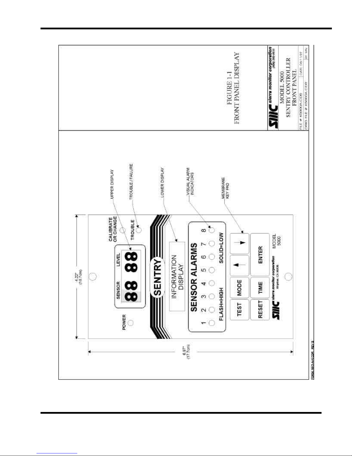
modules, management of alarm relays and interface with
the user via the front panel which includes a concentration
display, an alphanumeric display, keypad and status
indicators. The microprocessor functions are permanently
installed in the controller. They cannot be changed or
damaged by the user and will not be altered by loss of
power.
Configuration variables, such as alarm levels, can be
changed via a simple keypad sequence. Information
provided to the controller in this manner is retained even
when the power is interrupted. This information can be
protected by a "user code" to avoid unauthorized
modification.
Sentry continually scans all modules for alarm conditions.
No sequence of key presses can prevent the scanning
except specific actions during calibration or deliberate
disabling of the sensor module.
The Sentry controller is provided in a rack or panel mount
version for control rooms, an environmental enclosure for
outdoor, stand alone applications, or other packages for
specialty applications.
1.2.1 ENHANCEMENT PACKAGE
Various factory installed firmware enhancements are
available for the Sentry controller. These are selected at
the time of purchase or subsequent upgrade. The
enhancements, which are described in detail in the
appropriate sections of this manual, include:
− Addition of printer output firmware for models
5000-04 or 5000-02. Printer output is standard
on model 5000-08.
− Replace printer output firmware with MODBUS
data address protocol for host computer or DCS
interface. MODBUS is an industry standard
communication protocol which allows bidirectional communication via the controller RS232C serial port.
− High Alarm Acknowledge function for alarm
reset.
− Low Alarm Acknowledge function for alarm
reset
− Emergency Alarm function adds a third alarm
level.
− Zone and Voting assignment of individual alarm
relays.
− Analog Output software driver for use with
Model 4314-01 output module.
− Custom default Gas Tags and Engineering Units
Tags for up to eight input devices.
− Custom default Module Tags for up to eight
module addresses.
− Configure alarm relays to be normally energized
in the safe condition.
1.3 SENSOR MODULES
Each sensor module ("module") is labeled internally to
identify the type of gas it is designed to detect. For each
gas group, the sensor and the electronics board in the
explosion proof housing is different. During installation,
switches in the electronics are set by the user to give the
module an address (module number) to make it unique
from others in the same system. Sentry then
"communicates" with each module to determine its
number, the type of gas it detects, the gas concentration
and other information.
Inside the module housing is an electronic assembly
consisting of two printed circuit board assemblies mounted
under a metal top plate. The address switches and
adjustment potentiometers are accessible through the plate
and electrical test points (test lead jacks) are installed in
the plate. Connectors for wiring from the controller and
the sensor are located on the bottom of the electronic
assembly. The sensor is installed in one hub of the
enclosure.
PRODUCT DESCRIPTION
Page: 1
Page 8

SMC sierra monitor corporation Sentry Instruction Manual - Version 6
1.4 INTERCONNECT WIRING
Not supplied with Sentry, but necessary to the installation
and operation is the three conductor wiring which connects
the controller to the modules. Before this wiring is
installed it is important to read and understand the
installation instructions (Chapter 3) because significant
economies can be realized by connecting more than one
module onto a common wiring run. This standard feature
is accomplished by multiplexing the signals from the
modules to the controller.
1.5 DATA TRANSMISSION
Transparent to the user is the data transfer which occurs on
the installed interconnect wiring. Two of the conductors
are used to pass direct current (DC) from the controller to
the modules. The third wire transfers a series of very rapid
pulses between the controller and the sensor modules. This
digital transfer of information is an important feature of the
system which significantly reduces RFI and EMI problems.
1.6 POWER REQUIREMENTS
The standard system requires 120 VAC, 60 Hz, at 0.5 Amp
electrical supply. A factory option can be ordered for
220 VAC operation. DC voltage (12 to 28 VDC) can be
used for standby power. The system will automatically
switch to supplied DC operation at any time the AC
voltage is interrupted.
The system includes a lithium battery for RAM memory
retention during power interruptions. To ensure
continuous trouble free operation, however, the primary
power source must be one which is continuous and reliable,
preferably dedicated to this equipment. Battery back-up or
emergency power is recommended to insure continuous
operation.
PRODUCT DESCRIPTION
Page: 2
Page 9
SMC sierra monitor corporation Sentry Instruction Manual - Version 6
Figure 1-1
Front Panel Display
PRODUCT DESCRIPTION
Page: 3
Page 10
SMC sierra monitor corporation Sentry Instruction Manual - Version 6
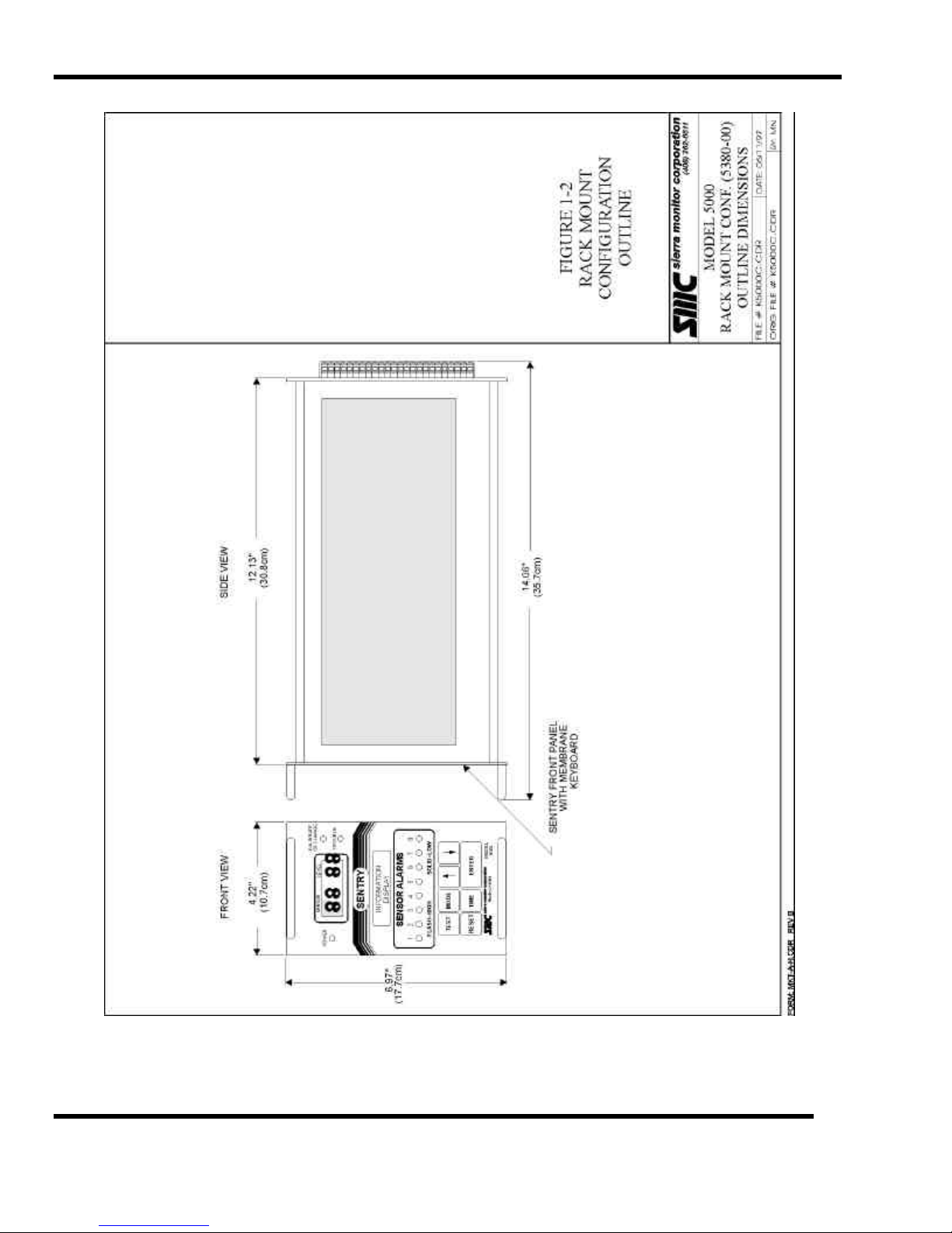
Figure 1-2
Rack Mount Configuration - Outline
PRODUCT DESCRIPTION
Page: 4
Page 11
SMC sierra monitor corporation Sentry Instruction Manual - Version 6
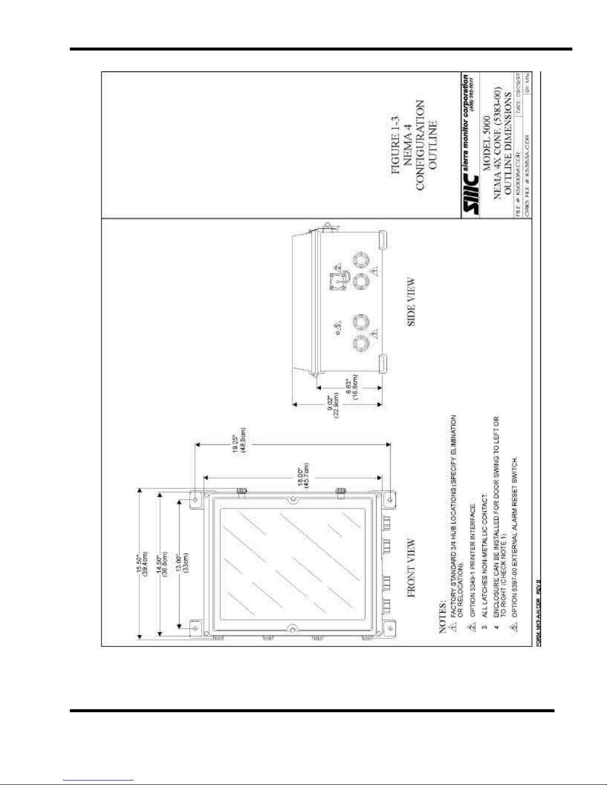
Figure 1-3
NEMA-4 Configuration - Outline
PRODUCT DESCRIPTION
Page: 5
Page 12
SMC sierra monitor corporation Sentry Instruction Manual - Version 6
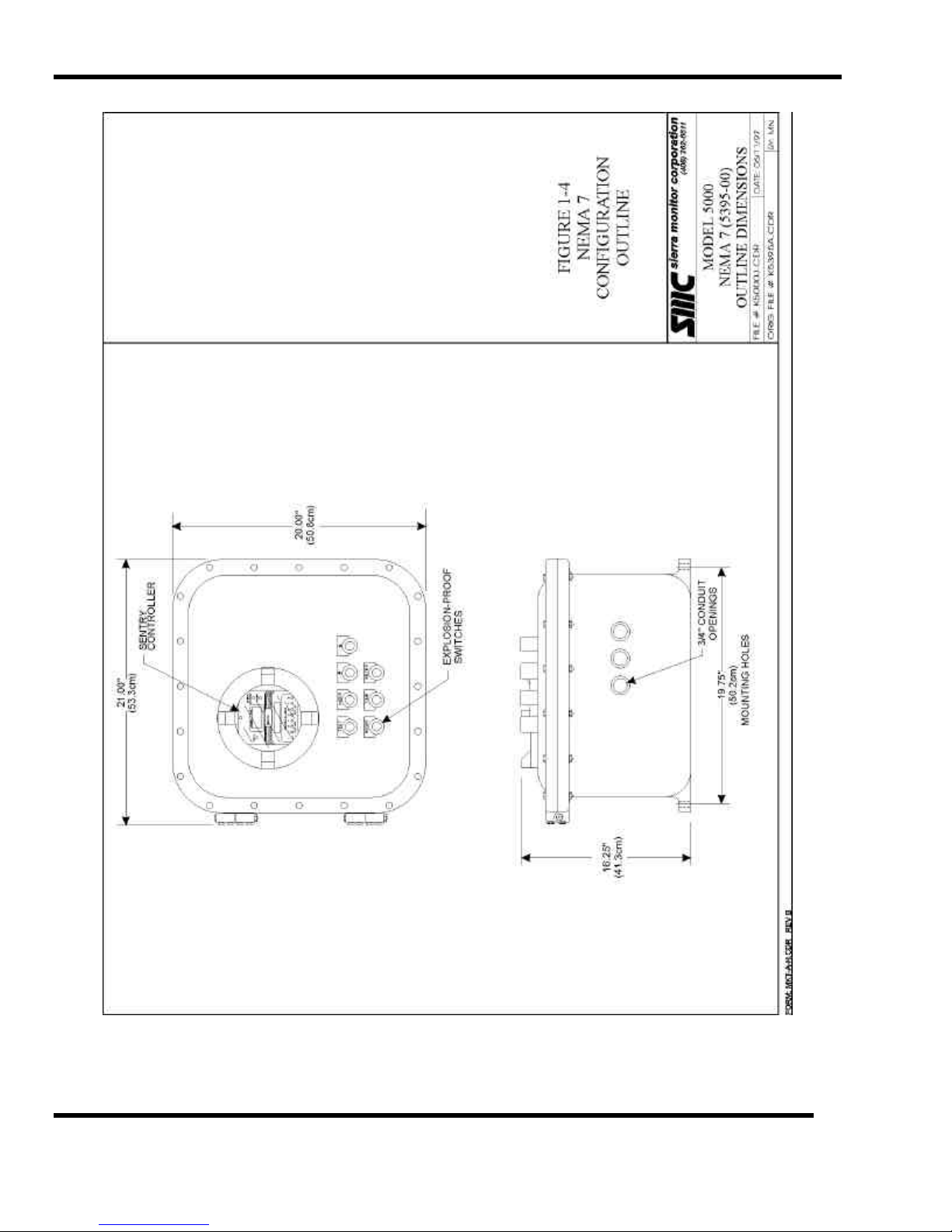
Figure 1-4
NEMA-7 Configuration - Outline
PRODUCT DESCRIPTION
Page: 6
Page 13
SMC sierra monitor corporation Sentry Instruction Manual - Version 6
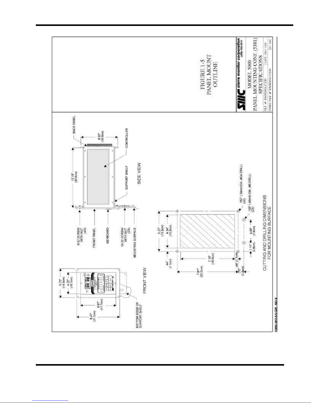
Figure 1-5
Panel Mount Configuration Outline
PRODUCT DESCRIPTION
Page: 7
Page 14
SMC sierra monitor corporation Sentry Instruction Manual - Version 6
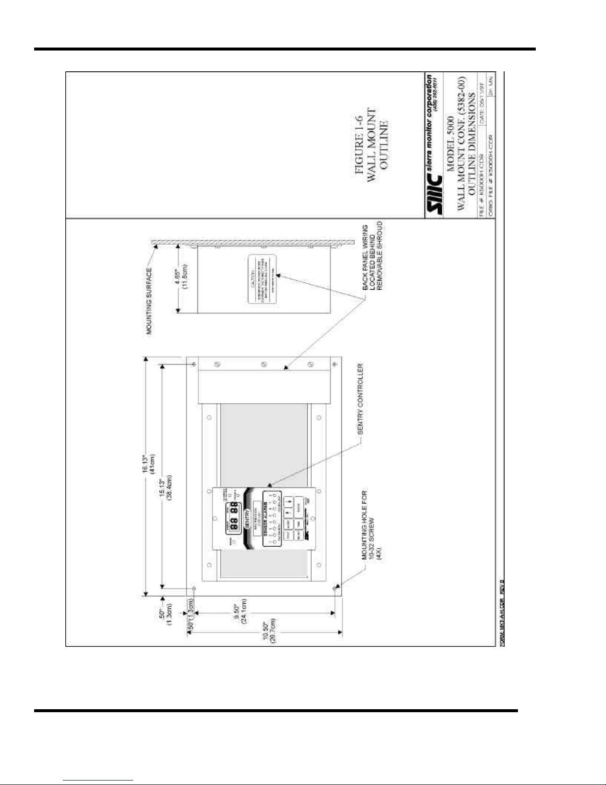
Figure 1-6
Wall Mount Configuration Outline
PRODUCT DESCRIPTION
Page: 8
Page 15
SMC sierra monitor corporation Sentry Instruction Manual - Version 6
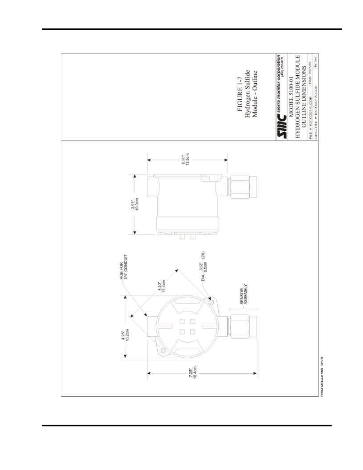
Figure 1-7
Hydrogen Sulfide Module - Outline
PRODUCT DESCRIPTION
Page: 9
Page 16
SMC sierra monitor corporation Sentry Instruction Manual - Version 6
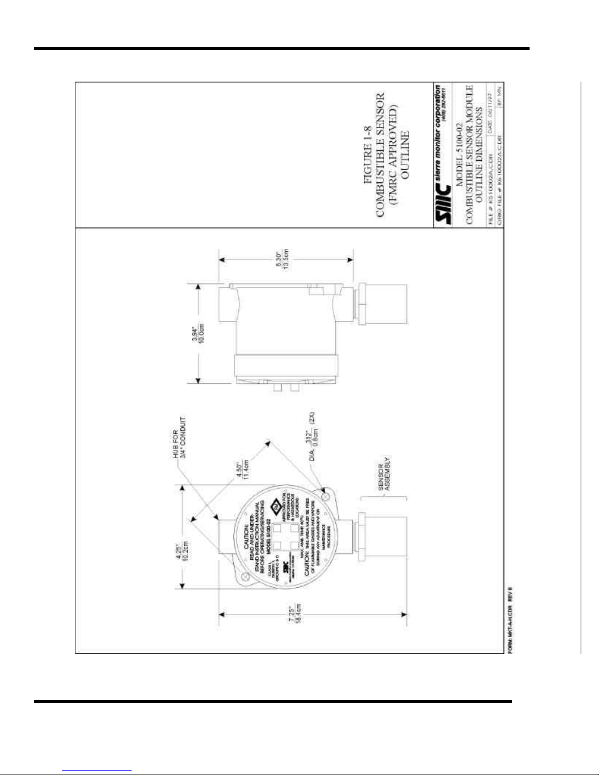
Figure 1-8
Combustible Sensor - Outline
PRODUCT DESCRIPTION
Page: 10
Page 17

SMC sierra monitor corporation Sentry Instruction Manual - Version 6
Figure 1-9
Oxygen and Toxic Sensor Modules - Outline
PRODUCT DESCRIPTION
Page: 11
Page 18
SMC sierra monitor corporation Sentry Instruction Manual - Version 6
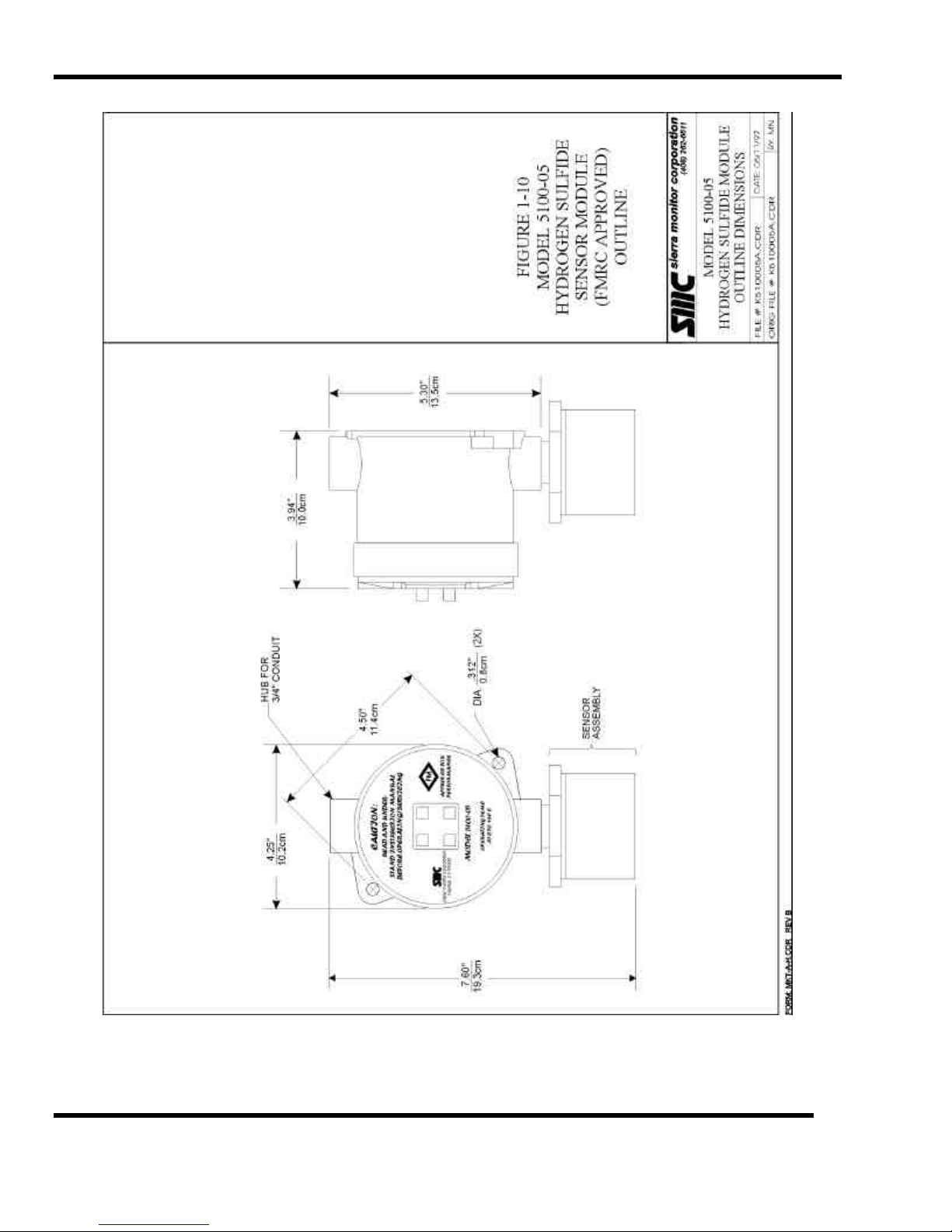
Model 5100-05 Hydrogen Sulfide Sensor Module (FMRC Approved) - Outline
Figure 1-10
PRODUCT DESCRIPTION
Page: 12
Page 19
SMC sierra monitor corporation Sentry Instruction Manual - Version 6
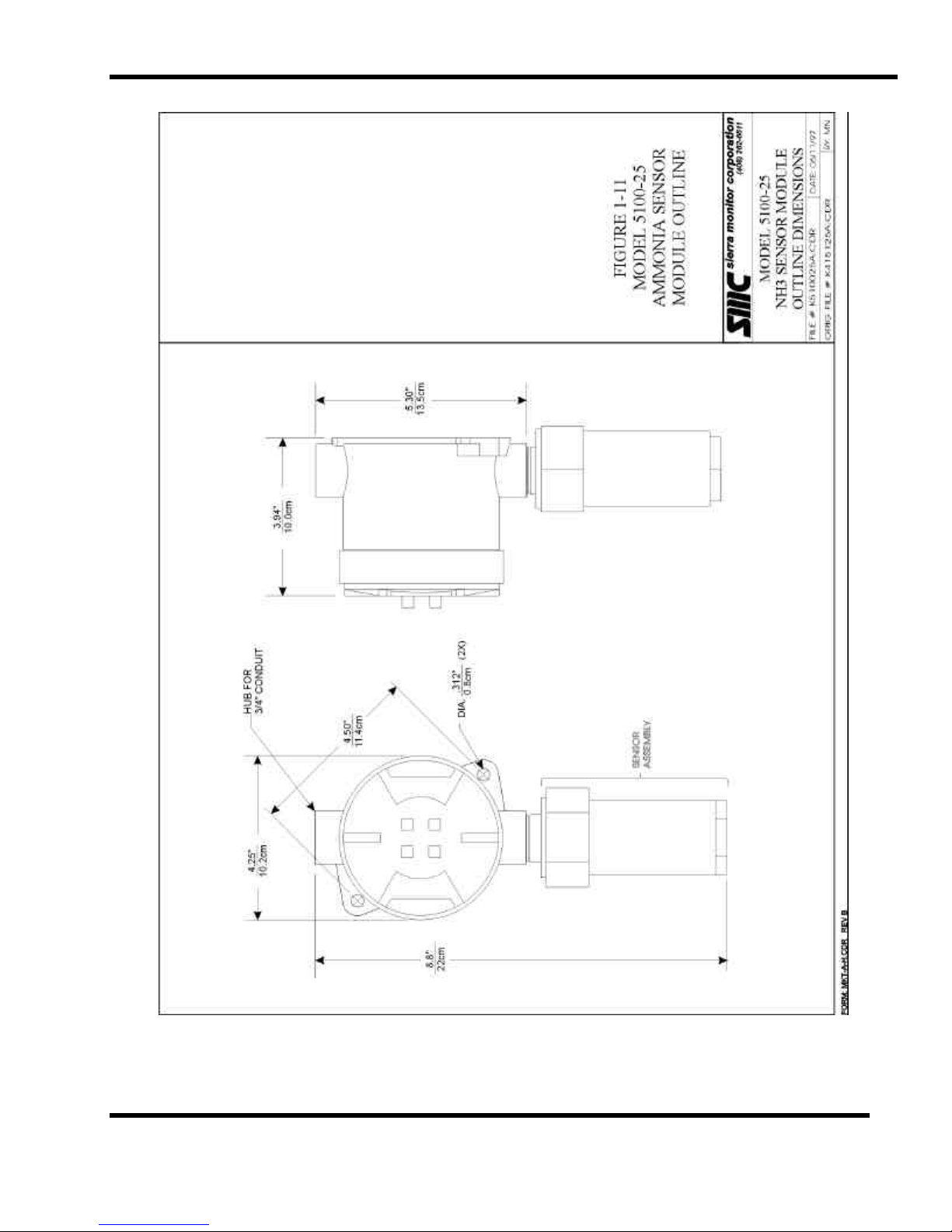
Figure 1-11
Model 5100-25 Ammonia Sensor Module - Outline
PRODUCT DESCRIPTION
Page: 13
Page 20

Page 21

SMC sierra monitor corporation Sentry Instruction Manual - Version 6
2. CAUTIONS & WARNINGS
2.1 INTRODUCTION
Although the Sentry system is designed and constructed
for installation and operation in industrial applications
including "hostile" environments, caution should be taken
to insure that the installation is made in compliance with
this instruction manual and that certain procedures and
conditions are avoided. This chapter discusses the
necessary cautions. Read the entire chapter prior to
installation of the equipment.
2.2 CONTROLLER
The controller should be installed in a location which is
safely accessible during a gas alarm.
Avoid installing the controller where it will be
unnecessarily exposed to wind, dust, shock or vibration or
direct sun. Observe temperature range limitations.
Adhere to standard electrical installation procedures. The
chassis ground on the controller must be connected to
earth ground.
2.3 WIRING
While the digital communication method used between
the controller and modules will greatly reduce problems
associated with electromagnetic and radio frequency
interference the manufacturer recommends that extra
caution be taken where the installation is near any sources
of these interferences:
• Avoid running sensor module cable close to high
power cables, radio transmission lines, or cables
subject to pulses of high current.
• Avoid running cables near large electric motors or
generators.
• When the risk of interference is present use shielded
cables. In conduit installations the shield should be
connected to the conduit. In cable applications the
shield should be connected to the cable connector.
• All splices must be via either a lug and terminal
system or soldered. Improperly spliced cable can
result in corrosion, resistance changes and system
errors.
NOTE
Installation and wiring must be in accordance with the
National Electrical Code
2.4 SENSOR MODULES - GENERAL
Avoid installing sensor modules where they will be
unnecessarily exposed to wind, dust, water (esp. direct
hose down), shock, or vibration. Observe temperature
range limitations.
Sensors may be adversely affected by prolonged exposure
to certain materials. Loss of sensitivity, or corrosion, may
be gradual if such materials are present in low
concentrations. These materials include: Halides
(compounds containing chlorine, fluorine, bromine,
iodine), silicones, acid vapors, caustic liquids or mists.
Care has been taken by the manufacturer to ship your
modules in protective packaging to avoid contamination
prior to installation. It is recommended that the sensors
remain protected during installation and that the covering
be removed immediately prior to system start-up.
During normal use the sensor is protected from dirt and
oil contamination by a sintered metal cover. If this cover
becomes clogged, the response of the sensor will be
reduced. Protect the sensor from contamination by careful
placement, or by use of rain and dust shields.
Sensor modules must not be painted. Paint may contain
compounds which will contaminate the sensor. Paint will
cause clogging of the sintered metal cover and will cause
difficulties during attachment of the calibration head or
other maintenance activity. It is recommended that the
module be tagged "DO NOT PAINT".
When sensors are replaced the thread must be Teflon
taped to avoid metal to metal binding which will damage
the housing threads.
2.4.1 COMBUSTIBLE SENSOR MODULES
Catalytic type combustible gas sensors may be poisoned
by exposure to silicones. Sierra Monitor Corporation
supplies resistant sensors, but care should be taken to
avoid exposure to silicones. No Silicone caulking (RTV)
should be used near the sensors. No other silicone based
compounds should be used near the sensors unless they
are fully protected during the entire cure cycle. If the
sensors will be exposed to silicone during normal
operation the manufacturer's sensor warranty is void.
CAUTIONS & WARNINGS
Page: 15
Page 22

Page 23
SMC sierra monitor corporation Sentry Instruction Manual - Version 6
3. INSTALLATION
All systems are factory are pre-configured and calibrated.
NOTE
All sensors are tagged to indicate the controller (alpha)
and the sensor module number (1 - 8).
Identify all components of the system during unpacking
and install using the factory configuration.
The system will power up in a calibrated and fully
functional condition.
3.1 CONTROLLER LOCATION
Rack mounted controllers should be installed in a control
room environment where they will be relatively free from
dust and temperature extremes. For ease of operation
select a rack window space at approximately eye level.
Four controllers can be installed side by side in a 19"
instrument shelf.
Enclosed controllers for outdoor applications should be
located in the most protected location available with
consideration for easy access for installation and
calibration. The enclosures should be mounted on a
vertical surface with the key board at approximately eye
level. The enclosure should not face directly into the sun.
3.2 SENSOR MODULE LOCATIONS
Select locations for each of the sensor modules based on
the following:
• Consider the density, relative to dry air, of the gas to
determine height of module above floor or ground
level:
Gas Density
(Air = 1.00)
Air 1.00
Ammonia 0.60
Carbon Monoxide 0.97
Chlorine 2.49
Ethylene Oxide 1.52
Hydrogen 0.07
Hydrogen Chloride 1.27
Hydrogen Cyanide 0.94
Hydrogen Sulfide 1.19
Methane 0.55
Nitrogen Dioxide 1.58
Oxygen (Air) 1.10
Sulfur Dioxide 2.26
• Modules should be placed close to the potential source
of gas.
• Modules should be placed in areas accessible for
calibration.
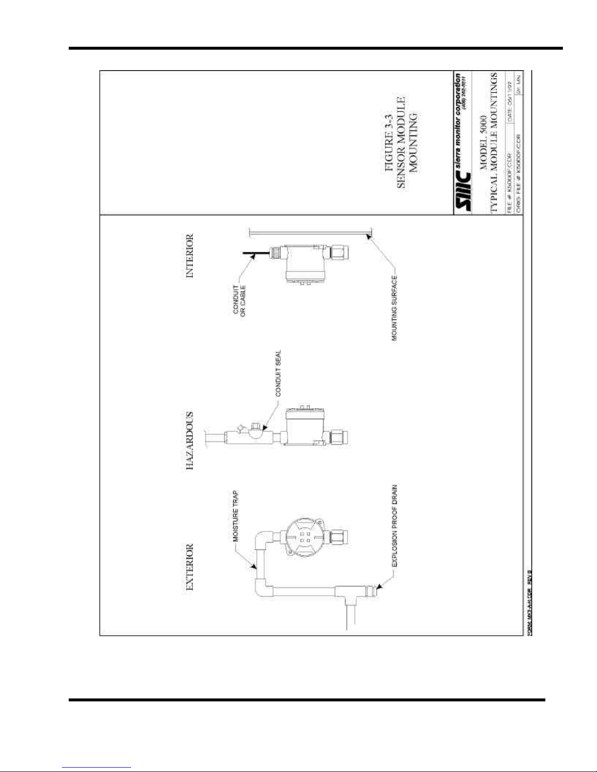
• Sensors should be pointed down and the conduit
should include an inverse trap to reduce moisture
(condensation) from accumulating in the electronics
enclosure Figure 3-3.
3.3 WIRING
Plan the wiring arrangement to minimize installation
expense but with redundancy for critical locations. Wire
shall be Belden (or equivalent) 949X (where X = 2, 3, 4, or
5 depending on wire gauge). If high RFI or EMI levels
exist wiring should be protected by conduit or shield.
Shielded wire shall be Belden (or equivalent) 936X.
In no case should the drain wire of shielded cable be used
as one of the conductors.
NOTE
• Any modules which are located in a common
geographical area a long distance from the controller
can be connected to the same three conductor wire run
installed from the controller to that area. Table 3-2,
Figure 3-4.
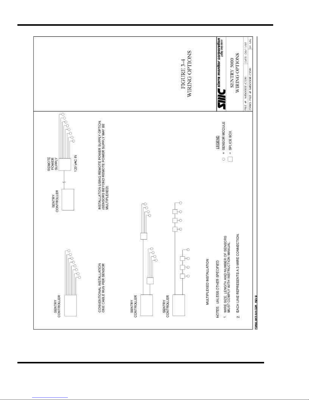
• The remote auxiliary power supply option can be used
for installation of one or more modules a long distance
from the controller location. The connection from the
controller to the remote power supply is via a two
conductor "data link" Figure 3-4.
Number of Maximum length of wire run (feet)
modules 500 1,000 2,000 3,000 5,000
1
2
3
4
20 20 18 16 14
20 18 14 12 xx
18 16 12 xx xx
16 14 12 xx xx
Table 3-2
Minimum Wire Gauges
Table 3-1
Specific Gravity of Selected Gases
INSTALLATION
Page: 17
Page 24
SMC sierra monitor corporation Sentry Instruction Manual - Version 6
Install conduit as required. Provide for splice boxes where
multiple modules will be wired to a single run. Pull 3
(typical: white, black, green) conductors of the correct
gauge wire from the controller to each splice box and from
the respective splice box to each planned module location.
See Figure 3-5 for proper wire termination in the splice
box. Twisted wire secured with wire nuts is not an
acceptable splice.
NOTE
Installation and wiring must be in accordance with the
National Electrical Code
In installations where redundancy of module locations is a
requirement do not install multiple modules on one cabling
run as any damage to the primary wiring will disable all the
modules.
NOTE
Temperature rating of cable wire insulation must be
above 75oC (85oC or greater rating wiring is
recommended). If cable runs through higher temperature
environments, it should be specified for that environment.
3.4 SENSOR MODULE INSTALLATION
Note: Remove spring from the electromechanical
sensor (5100-04 through 5100-23) prior to installation.
See technical note provided with sensor module.
1. Remove the electronics from the module housing
by:
• Unscrew the two captive panel screws in the
top plate.
• Lift the electronics out of the housing.
• Unplug the sensor harness from the bottom
electronics board.
2. Install the module housing onto the end of the
supply conduit and/or bolt into position as
required.
Note
If housing grounding is required for the installation a
grounding lug is located under the two printed circuit
assemblies in the housing. Install the ground wire under
the green lug. Figure 3-5
Controller
Marking
Function Module
Marking
Color
1 +VDC P White
2 Signal S Black
3 DC Return G Green
Table 3-3
Sensor Module Wiring
4. Reconnect the sensor harness to the sensor
connector on the bottom of the electronic
assembly. Figure 3-7.
5. Twist the assembly 180o to take up the service
loop on both the incoming wire and the sensor
harness. With the sensor facing down the wording
on the cover plate will be correctly oriented.
6. Carefully fit the electronics over the two posts in
the housing and tighten the captive panel screws.
Module Switch Positions
# 1 2 3
1 ON ON ON
2 OFF ON ON
3 ON OFF ON
4 OFF OFF ON
5 ON ON OFF
6 OFF ON OFF
7 ON OFF OFF
8 OFF OFF OFF
Table 3-4
Sensor Module Binary Switch Positions
7. Set the dip switch Figure 3-8 on each module to
indicate the module number (Table 3-4). Each of
the modules connected to one controller must have
a different address. (Note: Switch position 4 is not
used.)
3. Connect the three wires which run from the
controller to the three position terminal strip on the
bottom of the electronics assembly. See Table 3-3
for terminal markings and normal wiring color
code conventions. Figure 3-7 shows the correct
wiring connections and the operation of the
connector mechanism.
INSTALLATION
Page: 18
Page 25
SMC sierra monitor corporation Sentry Instruction Manual - Version 6
3.5 CONTROLLER INSTALLATION
3.5.1 CONTROLLER CONFIGURATIONS
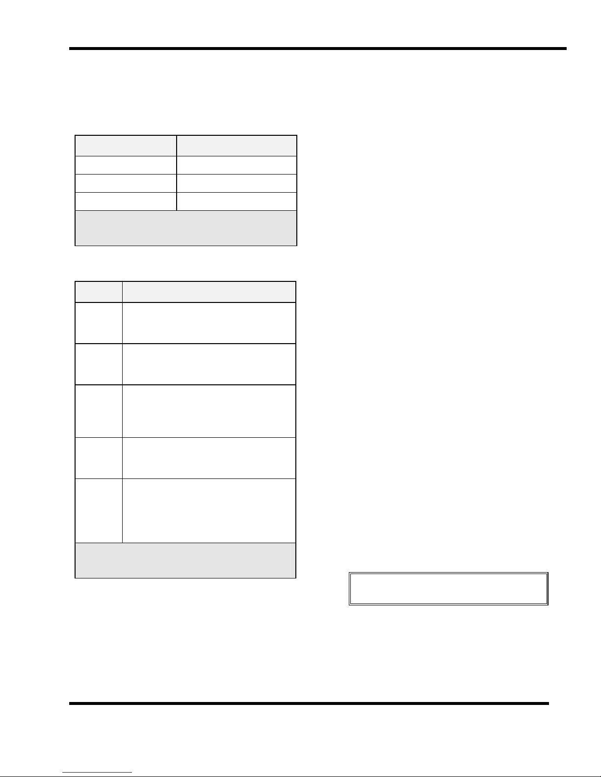
Table 3-5 lists the number of sensor modules which can be
operated on each controller model.
Model Controller Capacity
5000-02 2 Sensor Modules
5000-04 4 Sensor Modules
5000-08 8 Sensor Modules
Table 3-5
Sentry Controller Capacity
Table 3-6 lists and describes Sentry controller enclosure
options.
Model Description
5380-00 Standard configuration, controller
intended for installation in instrument
rack. Wiring to back connector panel.
5381-00 Controller supplied with bezel for panel
or chassis installation. Wiring to back
connector panel.
3.5.2.2 CHASSIS MOUNTED CONTROLLER
The chassis mounted controller is provided with a preinstalled bezel and a template for the chassis cut-out. An
angle bracket is also provided to support the cantilever of
the controller. Select an appropriate location at
approximately eye level providing rear access for the
module and alarm wiring.
3.5.2.3 WALL MOUNTED CONTROLLER
The wall mounted controller is provided on a sheet metal
panel containing brackets which allow for removal of the
controller. Select a location, where module and alarm
wiring can be run up or down the wall for distribution, and
bolt the panel to the wall.
3.5.2.4 NEMA ENCLOSED CONTROLLER
Mount the NEMA enclosed controller on a vertical surface
with the display at approximately eye level. Mounting feet
are supplied with the enclosure for external mounting bolts.
Figure 1-3. Although the enclosure is designed for
exposure to weather, normal measures to protect the
system from harsh conditions are recommended. It is
particularly important to avoid exposure of the display to
direct sunlight as this can cause fading of the display
during very hot weather.
5382-00 Wall mount configuration includes a
mounting panel and brackets, display is
side mounted. Wiring to side facing
panel.
5383-00 NEMA-4X Enclosure with latching front
door and window for viewing display.
Wiring to front facing terminal strips.
5395-00 NEMA-7 Explosion Proof Enclosure
with screw in window for viewing of
display and external switches for
operation of keypad. Wiring to side
facing panel.
Table 3-6
Sentry Enclosure Options
3.5.2 CONTROLLER MOUNTING
3.5.2.1 RACK MOUNTED CONTROLLER
The instrument rack should be installed in a 19" electronic
cabinet at eye level. Care should be taken to avoid heat
from other instruments under the controller.
3.5.2.5 WIRING CONNECTIONS
Channel wiring connections at the controller (except
NEMA-4X) and at the module are made using a quick
connect terminal strip. Figure 3-7. The terminal can be
operated using an actuator (supplied in the system
accessory bag) or by pressing a small screwdriver into the
actuator slot.
It is important to understand that, because of multiplexed
communication, there is a difference between "channel"
numbers and "module" numbers. Channels are the physical
connectors at the controller. Module numbers are the
switched addresses on each module. More than one
module number may be installed on a channel, up to a
maximum of four modules.
NOTE
Installation and wiring must be in accordance with the
National Electrical Code
Make the following connections at the controller.:
• Attach the three wires for each channel to separate
channel connectors on the terminal strip marked CH1
through CH8. The sequence should exactly match that
at the sensor assembly. (Typical: White 1, Black 2,
Green 3.)
INSTALLATION
Page: 19
Page 26
SMC sierra monitor corporation Sentry Instruction Manual - Version 6
• Connect the necessary remote audible and visual
alarms or other process control equipment to the
"HIGH", "LOW" and "TROUBLE" dry contact relays on
the connector panel.
The Double Pole/Double Throw (DPDT) relay
connections are marked to indicate Normally Open
(N/O) , Normally Closed (N/C) and Common (COM)
terminals for each pole. No voltage is applied to the
terminals internally.
Typical wiring configuration is described in Figure
3-11. The trouble relay is fail safe so that it will
switch from Normally Closed to Normally Open if all
system power is lost.
NOTE
It may be preferably to delay wiring the alarms, or delay
powering them, until the detection system has been fully
activated, tested and calibrated.
Connect 120 volts AC wiring to the terminals marked Hot
(black), Neutral (white), and Ground (Green).
If a 12-28 VDC supply is to be used as either back-up or as
the primary operating voltage make the necessary
connections to the terminal marked "DC INPUT 12 - 28V"
"+" (Red) & "-" (Black).
NOTE
When a battery is to be used for back-up DC supply only,
a Sentry feature provides protection against battery
damage by shutting off the battery before complete
discharge. When this feature is used, the Sentry
controller can only be restarted by AC voltage.
To implement the battery protection feature, two red
jumper wires located on the power supply board must be
cut. See Figure 7-3.
If splice boxes are used to combine multiple modules on a
channel the splice connections should be made using a
terminal block/wire lug assembly or all wires should be
soldered and insulated. Figure 3-5.
3.5.3 ALARM DEVICE INSTALLATION
Alarm devices must be installed according to the
manufacturer's instructions for the particular device.
Sentry dry contact relays provide switching capability as
rated in the specifications. (See Appendix A.)
NOTE
Certain warning strobes have a very high peak current
which is dependent upon the phase angle of the AC line at
the precise moment the strobe is switched on. A high
current at the time of switching may cause the relay
contacts to stick together.
The corrective action to avoid contacts sticking together is
to install a 10 Ohm, 5 Watt resistor in series with the
strobe power, preferably close to the relay.
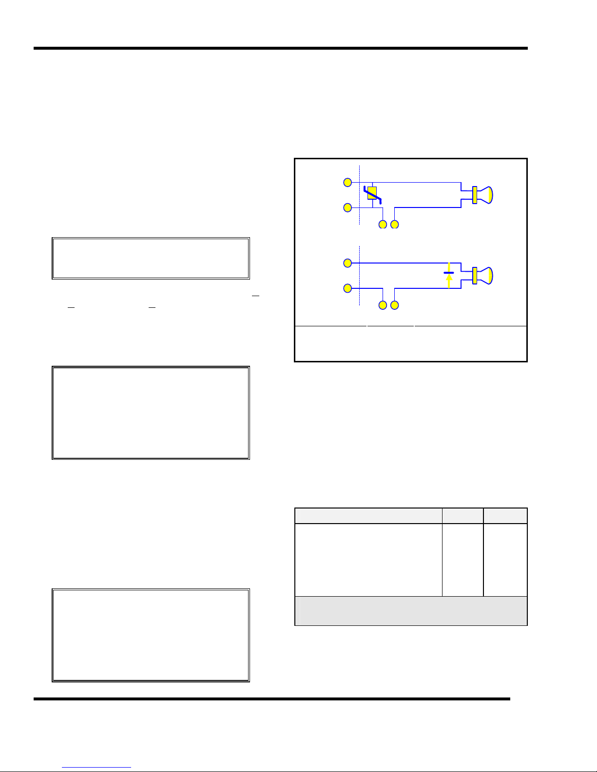
3.5.4 RELAY OUTPUTS
Three relays on the standard Sentry controller are for: high
alarm, low alarm and trouble. The trouble relay is
normally energized (power applied to coil). The gas alarm
relays (high and low) are normally not energized.
Individual low and high alarm relays are optional
hardware.
NO
RELAY
COM.
110 VAC
NO
RELAY
COM.
+ -
MOV
1N4005
DC
Install MOV
close to switch
Install diode
close to load
Figure 3-1
Typical Protection Circuit
The relays are dry contact and may be used to actuate bells,
lights, sirens, solenoid valves, or contactors as required. It
is recommended that for 120 VAC circuits a metal oxide
varistor (MOV) rated for 150 Vrms be place across the
load (Figure 3-1). (General Electric V150LA20A or
equivalent). For DC circuits a general purpose rectifier
diode should be placed across the load (1N4005).
3.5.5 DC POWER LOAD
Table 3-7 is provided to allow correct sizing of battery
back-up. To determine total load add the applicable
individual loads. (All measurements are at 12 VDC.)
Test Condition Amps Watts
Controller, No Sensors, No Alarms 0.560 6.7
Controller, No Sensors, All Alarms 0.660 8.0
Controller, 8 Combust, All Alarms 4.000 48.0
Individual Relay Board 0.750 9.3
Hydrogen Sulfide (Type 1) Module 0.260 3.1
Combustible (Type 2) Module 0.420 5.0
Electrochemical Sensor (typical) 0.050 0.6
Table 3-7
Sentry Power Load
INSTALLATION
Page: 20
Page 27

SMC sierra monitor corporation Sentry Instruction Manual - Version 6
3.5.6 POWER UP
Systems shipped complete from the factory are preconfigured and calibrated. When power is turned on the
power light will start flashing and the alpha-numeric
display will indicate "SYSTEM WARM-UP" "PLEASE WAIT
MM:SS" (where MM:SS is a five minute count-down
clock). When the warm-up ends the two displays will
begin functioning in the "continuous scan" mode which is
described in the next chapter. The large display will cycle
through each module number for any modules which have
been installed.
If modules have been added to the system since it was
factory configured, those modules will have a blank (“—“)
concentration display and the lower display will show the
module type and units with "FACTOR MISSING" or
"UNCALIBRATED" messages.
If the display indicates module numbers which match the
numbers used in installation, the wiring is correct and
module configuration can begin. If any number is omitted
the controller is not recognizing that module and the wiring
should be checked for errors (the system will display "NO
MODULE" when any attempt is made to obtain information
on that module).
If the controller does not recognize any modules the
display will read "NO MODULES INSTALLED".
NOTE
On 2 and 4 Channel systems any module set with a
number higher than four will cause the lower display to
indicate "MODULE # MUST BE 1 THROUGH 4" and
the upper display to display "#E --" (where # = the
erroneous module number).
3.5.7 POWER DOWN
If it is necessary to remove the power all operator
configured data and parameters will be saved by Sentry. (It
is important to turn off the main power prior to
disconnection of any module wiring because while under
power Sentry will interpret certain changes as errors.)
INSTALLATION
Page: 21
Page 28
SMC sierra monitor corporation Sentry Instruction Manual - Version 6
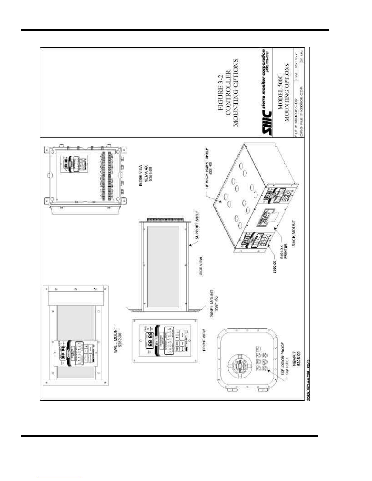
Figure 3-2
Controller Mounting Options
Page: 22
Page 29
SMC sierra monitor corporation Sentry Instruction Manual - Version 6
Figure 3-3
Sensor Module Mounting
Page: 23
Page 30
SMC sierra monitor corporation Sentry Instruction Manual - Version 6
Figure 3-4
Wiring Options
Page: 24
Page 31

SMC sierra monitor corporation Sentry Instruction Manual - Version 6
Figure 3-5
Typical Splice Box Wiring
Page: 25
Page 32

SMC sierra monitor corporation Sentry Instruction Manual - Version 6
Figure 3-6
Sensor Module Cross Section
Page: 26
Page 33

SMC sierra monitor corporation Sentry Instruction Manual - Version 6
Figure 3-7
Sensor Module Connector Detail
Page: 27
Page 34

SMC sierra monitor corporation Sentry Instruction Manual - Version 6
Sensor Module Top Plate Detail - Typical
Figure 3-8
Page: 28
Page 35

SMC sierra monitor corporation Sentry Instruction Manual - Version 6
Figure 3-9
Controller Connector Panel - Rack Configuration
Page: 29
Page 36

SMC sierra monitor corporation Sentry Instruction Manual - Version 6
Controller Connector Panel - NEMA-4X Configuration
Figure 3-10
Page: 30
Page 37

SMC sierra monitor corporation Sentry Instruction Manual - Version 6
Figure 3-11
Typical Alarm Wiring Configuration
Page: 31
Page 38

Page 39

SMC sierra monitor corporation Sentry Instruction Manual - Version 6
4. CONFIGURATION PROCEDURE
4.1 INTRODUCTION
Sentry is operated via the seven keys on the front panel.
Operation includes initial set-up, periodic calibration,
recall of history, and changes to configuration.
Certain procedure and message conventions are used to
provide consistency. A knowledge of these conventions
will aid in understanding of the set-up and operation steps.
The UP and DOWN arrow keys change information
displayed on the alpha-numeric (lower) display. Changes
made by using the arrows are not "implemented" until the
ENTER key is pressed.
The ENTER key is used to access the selected activity or to
enter selected data or status information into the controller
memory.
When any of the four activity keys TEST, RESET, TIME,
MODE are depressed the SENSOR/LEVEL display is
cleared and the activity information is displayed on the
alpha-numeric display.
The messages PRESS ENTER TO or ENTER TO indicate that
the selected activity can be accessed via the ENTER key.
If the ENTER key is pressed once during normal operation
the display locks onto the current module number and can
be advanced using the UP and DOWN arrow keys. When
the display is locked onto one module number the gas type
and units display is shown in round parenthesis “( )”.
If any module is force calibrated, the gas type and units
display for that module number is shown in square
parenthesis “[ ]”.
The message USE ARROWS/ENTER indicates that the
arrows can be used to change the module number or other
data on the second line and the ENTER can be used to
access the selected activity or module number.
Successive presses of any one of the four activity keys
will cycle through each option available and will return
the system to the normal operating mode..
When any activity key cycle has been started and not
completed the remaining activity keys are disabled except
that the RESET key can be used to return the system to
normal OPERATE mode.
When the system is in the CHANGE mode the CALIBRATE
OR CHANGE light is ON.
4.2 START-UP PREPARATION
The worksheet, Figure 4-1, will aid in understanding the
type of information required to set-up the system, it
should be completed prior to system power-up.
The message USE ARROWS/ENTER indicates that module
numbers or other variables can be changed with the
arrows prior to entering the activity with the ENTER key.
The message PRESENT CONFIG is used in system
responses during CHECK activities. Variables displayed
as PRESENT CONFIG can be changed via the CHANGE
mode.
Positive response messages such as SYSTEM RESET
COMPLETE are displayed for 1.5 seconds to confirm that
the activity has been completed.
Activity names are displayed bracketed by "<" and ">"
signs.
Normal operation is the condition where the change and
calibrate light is off and the display cycles continuously
between all active module numbers.
CONFIGURATION PROCEDURE
Page: 33
Page 40

SMC sierra monitor corporation Sentry Instruction Manual - Version 6
MODULE
ADDRESS
1
2
3
4
5
6
7
8
LOCATION SENTRY
CHANNEL
GAS
TYPE
LOW HIGH LATCH SCALING
FACTORS
SENSOR
SERIAL #
Figure 4-1
System Configuration Worksheet
NOTES
1 Module Address Dip switch setting for each sensor module
2 Location Describe the physical location of the module
3 Sentry Channel Log the channel number to which the module is wired
4 Gas Log the name of the gas which is to be detected
5 Low Alarm Enter the value for the low alarm
Default values are: H2S: 10 PPM, Combustible 20% LEL, Oxygen 19.5%, Toxic 10 PPM
6 High Alarm Enter the value for the high alarm
Default values are: H2S: 20 PPM, Combustible 60% LEL, Oxygen 16.5%, Toxic 20 PPM
Note: Combustible Alarms cannot be set greater than 60% LEL.
7. Latch L?/H? Determine if any module will require a latching alarm and write "Y" in the appropriate
position (e.g.: N/Y indicates a non-latching low alarm and latching high alarm, Y/Y
indicates both relays will be latching). The system "defaults are N/Y.
Note: Combustible High Alarms are Latching Only
8 Factors For H2S (5100-01): Record the three (three digit) numbers which are written on the sensor
connector on each sensor.
For Combustibles: If the gas to be detected and the gas to be used for calibration are the
same write "100".
If the calibration gas is methane and a different gas is to be detected select the correct factor
from XXXXX.
Note: Combustible Gas Scaling Factors are not FMRC approved.
No factors are required for Oxygen or Toxic sensors.
9 Sensor Serial Number Record the serial number from the label on the connector of each sensor
CONFIGURATION PROCEDURE
Page: 34
Page 41

SMC sierra monitor corporation Sentry Instruction Manual - Version 6
4.3 CONFIGURATION INSTRUCTIONS
Sentry controllers which are components of complete systems
are factory configured and generally do not require changes
prior to being placed in service.
Sentry controllers which have not been factory configured can
be placed into operation with default values for all configuration
parameters by using the diagnostic code “0021” described in
Section 8.3 of this manual.
The following are step-by-step configuration instructions which
can be used to customize the operation of the controller for
specific applications. After initial configuration the controller
can be placed in service or used for training as described in the
this section.
If an error is made, or suspected, press the RESET key until the
display reads <RESET SYSTEM> and then press the ENTER
key, the system will reset and the set-up routine can be restarted.
STEP KEY LOWER DISPLAY
1 RESET <RESET ALARMS>
2 RESET <RESET SYSTEM>
3 ENTER SYSTEM RESET COMPLETE
<UNCALIBRATED>
Displays continue cycling through each
module number. Power light changes from
flashing to solid.
4 MODE <CALIB/CHANGE>
5 ENTER CHANGE MODE SELECTED
Note that if a user entry code has been
initiated it must be input here.
Change/Calibrate light turns on.
READ INSTRUCTION MANUAL FIRST
PRESS ENTER TO CALIB ALL [GGGG]
Where GGGG is the gas type.
6 MODE <CHANGE CALIB>
7 MODE <CHANGE MODULE>
STEP KEY LOWER DISPLAY
15 ENTER FACTOR = 100
Linearizing factors are required for sensor
modules 5100-01 (H2S) .
Scaling factors can be used for sensor
module 5100-02 (Combustibles)
16 ENTER MODULE # = 2
Repeat steps 9 through 15 for each module.
17 MODE <SET USER CODE>
18 MODE <CHANGE PRINTER>
or
<CHANGE MODBUS>
Displays only if printer or MODBUS
option is installed.
19 MODE CHANGE GAS TAG
20 MODE CHANGE MOD TAG
21 MODE CHANGE ENG UNITS
22 MODE <OPERATE MODE>
23 ENTER OPERATE MODE SELECTED
24 TIME <CHECK HISTORY>
25 TIME <HISTORY REPORT>
For printer option only.
26 TIME <SYSTEM REPORT>
For printer option only.
27 TIME <STATUS REPORT>
For printer option only.
28 TIME <SET DATE & TIME>
29 ENTER D&T MM/DD HH:MM
Set each digit using the arrows, then
ENTER to advance to the next digit.
28 RESET H2S PPM
Display will scan through all active gas
sensor modules.
8 ENTER USE ARROWS/ENTER
MODULE # = 1
9 ENTER GAS TYPE : GGGG
10 ENTER # 1 GGGG IS: ON
11 ENTER LO ALM: NONLATCH
12 ENTER HI ALM: LATCH
13 ENTER HIGH ALARM = XX
14 ENTER LOW ALARM = XX
Use arrows to change.
Use arrows to change.
Use arrows to change each digit.
Use arrows to change each digit.
4.4 SENTRY TRAINING
After the controller is configured use this section in conjunction
with the Sentry MENU, Table 4-2, and Sentry
FLOWCHARTS, Figure 4-3 through Figure 4-7 to develop an
understanding of keyboard operation.
To begin, press the RESET key until the lower display reads
PRESS ENTER TO RESET SYSTEM then press ENTER.
The system is now in "normal operate mode". The Sensor/Level
display will cycle through each of the module numbers
(CONTINUOUS SCAN). If any module is indicated as
MODULE OFF use steps 9 through 15 of Section 4.3 to turn
that module ON.
CONFIGURATION PROCEDURE
Page: 35
Page 42

SMC sierra monitor corporation Sentry Instruction Manual - Version 6
In NORMAL OPERATE mode Sentry scans all modules in
sequence and displays their current readings. For any
modules which are not correctly initiated and calibrated
the status will be indicated. This scanning sequence is by
module number by type. (Type 1 = H2S solid state, Type
2 = Combustible, Type 3 = Oxygen and Type 4 = all
others)
For H2S, Combustible and Toxic modules the upper
(Sensor/Level) display indicates the module number and
the concentration. The lower display shows the gas tag
and the engineering unit.
For Oxygen the upper display indicates the module
number and its deficiency status. The lower display will
read the oxygen concentration (e.g.: 20.9%).
Table 4-1 indicates display conditions for each module
type.
Type Gas/Status Upper Lower
1 H2S Normal 00 H2S PPM%
2 Combustible Normal 00 COMB* %LEL
3 Oxygen Normal 00 OXY 20.9%
3 Oxygen Below Normal LO OXY <20.7%
3 Oxygen Above Normal HI OXY >21.1%
4 Toxic Normal 00 TOXIC* PPM
* “COMB” and “TOXIC” gas tags can be modified to any six
character tag using CHANGE GAS TAGS.
Table 4-1
Display Conditions
CONTINUOUS SCAN is Sentry's default display mode. To
"lock" the display onto one module wait till that module is
displayed and press ENTER. While the "lock" is in effect
the arrows can be used to change to other module
numbers. The lock is indicated by "( )" around the top
line of the lower display. To return to CONTINUOUS SCAN
press ENTER.
Other user selectable display modes are described later in
this manual.
Press the TEST button, read the display, then press the
TEST button again. Repeat until the system returns to the
continuous scan display. The two test conditions which
are displayed are: <TEST SYSTEM> and <TEST ALARMS>.
Neither of these tests were implemented because the
ENTER key was not pressed.
Model number, software level, and traceability
descriptors.
MODEL 5000 VERS 6.3
8 CH 951234
Low Alarm Test with relays inactive.
RELAYS PASSIVE
TEST LOW ALARMS
High Alarm Test with relays inactive.
RELAYS PASSIVE
TEST HIGH ALARMS
Trouble Alarm Test with relays inactive.
RELAYS PASSIVE
TEST TROUBLE
ALARM
Full Display Test with all display segments and LED’s on.
X X X X X X X X X X X
X X X X X X X X X X X
Warm-up Time-out.
SYSTEM WARM-UP
PLEASE WAIT 5:00
Return to normal scan.
COMB %LEL
MODULE TAG
Press the TEST key twice and the display will read TEST
ALARMS. Press the ENTER key and Sentry will execute
LOW, HIGH & TROUBLE alarms and then return to the
operate mode. During this test the respective alarm relays
will throw. The user code described later in this manual
can be used to protect against unauthorized activation of
the alarm relays.
Read the Sentry menu, Table 4-2 to find the TEST key. It
should now be easy to understand that each step in the
menu can be implemented by using the enter key or
bypassed by continuing to press the activity key. This
process is further described in the flowcharts. Figure 4-3
through Figure 4-7.
To implement the tests, press the TEST key once; display
will read <TEST SYSTEM>. Press the ENTER key. Sentry
will then step through the following series of displays:
CONFIGURATION PROCEDURE
Page: 36
Page 43

SMC sierra monitor corporation Sentry Instruction Manual - Version 6
4.5 SENTRY MENU
Table 4-2 describes the primary activities that can be accessed
via the Sentry keyboard. Each activity which involves submenu selection is identified by an asterisk Menu selections
which refer to printer are standard in eight channel systems,
optional in two and four channel systems. The MODBUS
option replaces Printer software.
Menu selections are further described in the following
paragraphs. Press the respective key to select the sub-routines
and press the ENTER key to access them. Follow the sequence
in the flow charts.
MENU KEYS
TEST RESET TIME MODE
SYSTEM ALARMS HISTORY CALIBRATE/
ALARMS SYSTEM PRINT HISTORY SELECT SCAN
HISTORY PRINT SYSTEM
REPORT
PRINT STATUS
REPORT
SET DATE &
TIME
CHANGE
CHECK CALIB
CHECK MODULE
CHECK PRINTER
− Lowest concentration LC with date and time
− Last Calibration with date and time.
− Last logged error with date and time (if applicable).
At the end of the sequence the display will indicate the next
module number and will continue to automatically increment as
the data is recalled. If the data from a particular module is not
required press the UP arrow to manually increment the number.
As this recall sequence is a continuous "loop", press the RESET
key at any time to return to the OPERATE MODE.
The history information may be collected on a continuous basis
without clearing the data because only the last occurrence of
each level will be retained. History data can be cleared by using
the RESET HISTORY menu selection. Error messages are
cleared by using the RESET SYSTEM menu selection.
4.5.2.2 PRINT HISTORY
PRESS ENTER TO
PRINT HISTORY
When the printer option is installed in Sentry this menu choice
can be used to print all the module history.
4.5.2.3 PRINT SYSTEM
Sentry Primary Menu Selection
Table 4-2
4.5.1 TEST KEY
The TEST KEY activities are described in the training exercise
in Section 4.4.
4.5.2 TIME KEY
4.5.2.1 CHECK HISTORY
PRESS ENTER TO
CHECK HISTORY
The first display in the CHECK HISTORY menu shows the
system clock date and time D/T on the first line. The second
line shows the date and time at which the history information
was last cleared HR.
The second display indicates the last time the power was
interrupted. PD is the Power Down time and PU is the Power
Up time. After any interruption of power to the controller the
POWER light will flash until the system is reset.
The third display begins the sequence in which the history for
any module can be recalled. The display will indicate
MODULE NUMBER 1. Successive presses of the ENTER
key will result in display of:
PRESS ENTER TO
PRINT SYSTEM
When the printer option is installed in Sentry this menu choice
can be used to print a complete system configuration report.
4.5.2.4 PRINT STATUS
PRESS ENTER TO
PRINT STATUS
When the printer option is installed in Sentry this menu choice
can be used to print a status report which indicates the present
status and concentration for each module.
− Date and time of the last low alarm LA and high alarm
HA
− Highest concentration HC with date and time
CONFIGURATION PROCEDURE
Page: 37
Page 44

SMC sierra monitor corporation Sentry Instruction Manual - Version 6
4.5.2.5 SET DATE/TIME
PRESS ENTER TO
SET DATE & TIME
Set the Sentry clock in the same manner as any digital clock is
set. The format is MM/DD HH:MM, with the hours set in
military time (24 hours). If a user code has been set-up it will be
required prior to changing the clock. The cursor is initially
under the month MM, set the correct month with the arrow and
press ENTER to advance to the day DD. Repeat the process to
set day, hour and minute. When the time is correct, press
RESET to exit.
4.5.3 RESET KEY
4.5.3.1 RESET ALARMS
PRESS ENTER TO
RESET ALARMS
The RESET ALARMS activity will reset any latched alarm
relay when the condition which caused the alarm has been
corrected. If RESET ALARMS is selected before the
correction has been made, the respective LED and relay will
remain in the alarm condition.
4.5.3.2 RESET SYSTEM
PRESS ENTER TO
RESET SYSTEM
4.5.3.5 EXTERNAL RESET KEY
The external RESET key on NEMA units implements RESET
ALARMS and eliminates the need to open the enclosure for this
purpose.
4.5.4 MODE KEY - CALIB/CHANGE
The first menu choice under the MODE key is
CALIB/CHANGE when the ENTER key is pressed the
"Calibrate or Change" light will turn on and the display will
indicate ENTER TO CALIB (GAS TYPE) (SPAN VALUE).
After initial system set-up the CALIBRATE OR CHANGE
activity should be protected via the user access code described
in Section 7.3.4. When the user code has been installed only
authorized operators may access this activity.
4.5.4.1 CALIBRATE
ENTER TO CALIB
COMB 50% LEL
The calibration activity is described in detail in the next chapter.
4.5.4.2 CHANGE CALIB
PRESS ENTER TO
CHANGE CALIB
The change calibration activity is described in detail in the next
chapter.
The RESET SYSTEM activity wi ll reset all trouble conditions.
If the trouble still exists the condition will re-display
immediately. RESET SYSTEM can be used at any time to
return the system to normal operation and clear all error
messages.
4.5.3.3 RESET HISTORY
PRESS ENTER TO
RESET HISTORY
The RESET HISTORY activity clears all module history
information which is normally accessed via the TIME key. The
highest concentration is set to 00 and the lowest concentration is
set to HI. The history reset date/time is set to the current system
date/time. Sentry will immediately begin collecting new history
information. When a user code has been installed the code will
be required before the history can be reset.
4.5.3.4 OTHER USE OF RESET KEY
During CHANGE activity if the RESET key is pressed once
the display will return to its normal scan operation but the
CHANGE/CALIBRATE light will remain on. The MODE
key can then be used to return to configuration activities without
re-entering a user code. This action is helpful if module scan
information is required during a configuration step.
4.5.4.3 CHANGE MODULE
PRESS ENTER TO
CHANGE MODULE
Each module in the installation must be initialized via the
change module activity. The CHANGE MODULE activity is
detailed in step by step form in Section 4.3 steps 6 through 18.
The CHANGE MODULE activity should also be used after
any sensor or module has been replaced to insure that the correct
alarm limits and factors have been established.
CONFIGURATION PROCEDURE
Page: 38
Page 45

SMC sierra monitor corporation Sentry Instruction Manual - Version 6
4.6 SET USER CODE
PRESS ENTER TO
SET USER CODE
To avoid unauthorized access to the configuration activity the
USER CODE should be set as soon as the Sentry has been put
on line. User codes are described in Section 8.3. Special
diagnostic routines, also accessible via the user code, are
describe in the same section.
4.6.1.1 CHANGE PRINTER / MODBUS
PRESS ENTER TO
CHANGE PRINTER
CHANGE MODBUS
The CHANGE PRINTER or CHANGE MODBUS sub menu
will appear if printer or MODBUS software is installed on the
Sentry. Printer and MODBUS software is described in Section
8.5.
4.6.1.2 CHANGE GAS TAG
PRESS ENTER TO
CHANGE GAS TAG
The system default GAS TAG list contains eight common toxic
gas names. (CO, H2S, CL2, SO2, NO2, HCL, H2, NH3). The gas
tag names, and their corresponding engineering units can be
changed. At the menu prompt press ENTER and the first gas
tag will appear. Press ENTER to begin edit, or press ARROW
to select a different gas tag.
Edit the tag by pressing the ARROW unit the correct character
is selected, then ENTER to advance to the next character. The
gas tag allows six characters, the engineering units allow four
characters.
4.6.1.3 CHANGE MODULE TAG
PRESS ENTER TO:
CHANGE MOD
TAG
The system default MODULE TAGS are blank for all modules
unless changes have been ordered through the enhancement
package. Module tags can be changed or edited.. At the menu
prompt press ENTER and the first module number will display.
Press ENTER to begin edit, or press ARROW to select a
different module number.
Edit the tag by pressing the ARROW unit the correct character
is selected, then ENTER to advance to the next character. The
module tag allows sixteen characters,. It is recommended that
shorter tags be centered by leaving leading blank.
When the OPERATE MODE is selected by pressing ENTER
the Change/Calibrate light turns off and Sentry returns to the
pre-selected scanning mode.
4.6.2 MODE KEY - OTHER
If the first MODE key activity CALIB/CHANGE is not
required the following menu selections can be accessed by
successive presses of the MODE key:
4.6.2.1 SELECT SCAN
PRESS ENTER TO
SELECT SCAN
Select the controller scan mode during normal operation. This
selection only affects the display and does not change the alarm
or relay activity. The scan mode can be selected by successive
presses of the ARROW key. and implemented by implemented
by pressing the ENTER key.
1. HIGHEST MODULE: Sentry will find the highest reading
module and will display only that module until another
module exceeds the first level. Under certain conditions the
display will cycle from one module to another in this mode,
those conditions are:
• More than one module at the same level.
• More than one module type in use (when two types
are in use the highest of each type will display
alternately.
• All modules in alarm condition will display.
• Any module which is uncalibrated, off, or in trouble.
2. CONTINUOUS: The display continuously cycles through
all modules. When two types of module are in use all "Type
1" (H2S) will be displayed, followed by all "Type 2" (CH4)
etc..
3. SAFE SCAN: When all modules are below their respective
alarm level Sentry will display a "- -" on the upper display
and CONDITION SAFE on the lower display. When any
module(s) exceeds it's alarm level that module's information
will display. Modules which are uncalibrated, off or in
trouble will also display.
4.6.1.4 OPERATE MODE
PRESS ENTER TO:
OPERATE MODE
CONFIGURATION PROCEDURE
Page: 39
Page 46

SMC sierra monitor corporation Sentry Instruction Manual - Version 6
4.6.2.2 CHECK CALIB
PRESS ENTER T O:
CHECK CALIB
The present calibration parameters can be check by
successive presses of the ENTER key. These include the
gas type, full scale, concentration of calibration gas, the
number of days between calibrations and the status of
global calibrate.
4.6.2.3 CHECK MODULE
PRESS ENTER TO:
CHECK MODULE
Any module number can be selected and configuration
information for that module recalled. Select the module
number using ARROWS, then step through the
configuration information using the ENTER key.
MEASUREMENT OVERRANGE - When Combustible
concentration exceeds the 99% LEL range of the
instrument, the controller displays "HI".
4.6.2.4 CHECK PRINTER
NOTE
PRESS ENTER T O:
CHECK PRINTER
Press ENTER to review printer configuration.
CONFIGURATION PROCEDURE
Page: 40
Page 47

SMC sierra monitor corporation Sentry Instruction Manual - Version 6
SENTRY KEY BOARD
Ts = TEST R = RESET M = MODE T = TIME ^ = ARROWS E = ENTER
RESET KEY * GLOBAL CALIBRATION
Reset Alarms R E Gas Type (Concentration) ^ E
Reset System R R E Enter to Span E
Reset History R R R E Apply Zero Gas E
TIME KEY Enter to Span E
Check History T E Apply Span Gas E
Printer History T T E Operate Mode (After timer) E
Print System T T T E * LOCAL CALIBRATION
Print Status T T T T E Gas Type (Concentration) ^ E
Set Date & Time T T T T T E Apply Zero & Span E
TEST KEY Operate Mode (After timer) E
Test System Ts E * CHANGE MODULE
Test Alarms Ts Ts E Module # ^ E
MODE KEY - PASSIVE Gas Type ^ E
Change/Calib M E Module On/Off ^ E
Select Scan M M E Low Alarm Latch/Non ^ E
Check Calib M M M E High Alarm Latch/Non ^ E
Check Module M M M M E High Alarm Value ^ E ^ E ^ E
MODE KEY - ACTIVE Low Alarm Value ^ E ^ E ^ E
Change/Calib M E Scaling Factors ^ E ^ E ^ E
Calibrate * E * SET USER CODE
Change Calibrate * M E User Number ^ E
Change Module * M M E Entry Code ^E ^E ^E ^E
Set User Code * M M M E * CHANGE PRINTER
Change Printer * M M M M E Printer On/Off ^ E
Change Gas Tag M M M M M E Controller ID ^^ E
Change Module Tag M M M M M M E Status Frequency ^^ E
* CHANGE CALIB Print History ^ E
Gas Type ^^ E Gas Type ^^ E
Full Scale ^^ E ^^ E ^^ E Min. Conc. ^^ E
Calib Concentration ^^ E ^^ E ^^ E Conc. Change ^^ E
Calib Frequency ^^ E Gas Type ^ E
Global Calib ^ E Exit R
Figure 4-2
Sentry Keyboard - Quick Help
CONFIGURATION PROCEDURE
Page: 41
Page 48

SMC sierra monitor corporation Sentry Instruction Manual - Version 6
OPERATE MODE
RESET
RESET ALARMS ENTER
RESET
RESET SYSTEM
RESET
RESET HISTORY
ENTER CODE?
ALARMS RESET
SYSTEM RESET OPERATE MODEENTER
Y
N
VALIDRESET
Y
RESET HISTORYACCESS DENIED
OPERATE MODE
N
RESET
COMPLETE
RETURN TO OPERATE MODE
Figure 4-3
Sentry Reset Key Flow Chart
CONFIGURATION PROCEDURE
Page: 42
Page 49

SMC sierra monitor corporation Sentry Instruction Manual - Version 6
OPERATE MODE
TEST
TEST SYSTEM ENTER
TEST
TEST ALARMS
TEST
ENTER
ACCESS DENIED
SYSTEM TEST
FUNCTIONS
CODE?
Y
N
VALID
Y
ACTIVE
LOW ALARM
ACTIVE
HIGH ALARM
ACTIVE
TROUBLE
SENTRY REV #
IDENTIFIERS
PASSIVE LOW
ALARM
PASSIVE HIGH
ALARM
PASSIVE
TROUBLE
FULL DISPLAY
TEST
RETURN TO OPERATE MODE
Figure 4-4
Sentry Test Key Flow Chart
CONFIGURATION PROCEDURE
Page: 43
Page 50

SMC sierra monitor corporation Sentry Instruction Manual - Version 6
OPERATE MODE
TIME
CHECK HISTORY ENTER
DATE & TIME
HISTORY RESET
TIME
POWER DOWN
POWER UP
HISTORY
REPORT
ENTER
ENTER
REPORT
TIME
SYSTEM
REPORT
TIME
STATUS
REPORT
TIME
SET DATE &
TIME
TIME
REPORT
COMPLETE
ENTER
ENTER
ENTER CODE?
N
ACCESS
DENIED
REPORT
REPORT
COMPLETE
REPORT
REPORT
COMPLETE
VALID?
CHANGE
MM/DD HH/MM
ENTER
ENTER
ENTER
ENTER
ENTER
ENTER
Y
Y
N
END?
Y
TIME
CHANGE
MODULE NO.
LOW ALARM D/T
HIGH ALARM D/T
LOWEST CONC.
VALUE D/T
HIGHEST CONC.
VALUE D/T
LAST CALIB.
DATE/TIME
ERROR LOG
IF APPLICABLE
N
ENTER
RETURN TO OPERATE MODE
TIME
Figure 4-5
Sentry Time Key Flow Chart
CONFIGURATION PROCEDURE
Page: 44
Page 51

SMC sierra monitor corporation Sentry Instruction Manual - Version 6
OPERATE MODE
MODE
CALIB OR
CHANGE
MODE
SELECT SCAN
MODE
CHECK CALIB ENTER
MODE
CHECK MODULE ENTER
ENTER
ENTER
CODE
N
VALID
ENTERS CHANGE
MENU (MODE KEY
ACTIVE))
CONTINUOUS
SAFE SCAN
HIGHEST SENSOR
GAS, CONC,
FULL SCALE
FREQUENCY
GLOBAL?
MODULE #, ON/OFF
ALARMS LATCH?
ALARM VALUES
FACTORS
Y
N
ACCESS
DENIED
SELECT
USING
ARROWS
ENTER
ENTER
ENTER
MODE
CHECK PRINTER
MODE
ENTER
PRINTER ON/OFF
CONTROLLER ID
PRINT CONFIG.
RETURN TO OPERATE MODE
Figure 4-6
Sentry Mode Key (Passive) Flow Chart
CONFIGURATION PROCEDURE
Page: 45
ENTER
Page 52

SMC sierra monitor corporation Sentry Instruction Manual - Version 6
OPERATE MODE
MODE
CALIB OR
CHANGE
ENTER
CODE
VALID
N
READ
INSTRUCTIONS
ACCESS
DENIED
CALIBRATE ** ENTER
MODE
CHANGE
CALIBRATE
MODE
CHANGE
MODULE
Y
N
MODE
SET USER CODE
MODE
CHANGE
PRINT/ MODBUS
MODE
ENTER
ENTER
ENTER
ENTER
CALIBRATION
PROCEDURE
CHANGE CALIB
PROCEDURE
CALIBRATE **
MODULE CONFIG.
PROCEDURE
USER CODES AND
DIAGNOSTICS
EDIT PRINTER OR
MODBUS PROCEDURE
CHANGE
GAS TAG
MODE
CHANGE
MOD TAG
MODE
RETURN TO OPERATE MODE
ENTER
ENTER
Figure 4-7
Sentry Mode Key (Active) Flow Chart
CONFIGURATION PROCEDURE
Page: 46
EDIT GAS TAGS
PROCEDURE
EDIT MOD TAGS
PROCEDURE
Page 53

SMC sierra monitor corporation Sentry Instruction Manual - Version 6
5. CALIBRATION
5.1 SENTRY CALIBRATION - AN OVERVIEW
Calibration is a simple three step process:
1. Initiate calibration via the controller keyboard.
2. Apply zero gas (if required) and then span gas to the
sensors.
3. Close the calibration via the controller keyboard.
Calibration parameters are configured via the CHANGE
CALIB activity and are saved by Sentry for future calibrations.
During calibration Sentry "peak holds" the sensor signal output
for zero and span gas and then uses those values to construct a
curve for continuous reference during normal gas monitoring.
There are two alternative calibration methods, Global
Calibration and Local Calibration.
5.1.1 GLOBAL CALIBRATION
When Global Calibration is selected, the Sentry controller
collects zero and span value data from all sensor modules
eligible for calibration based on a global keyboard command. It
is not necessary to calibrate all the sensors, those which do not
receive span gas will be rejected automatically.
The operator presses the ENTER key to initiate, and complete,
collection of the zero value and then the span value. Calibration
gas may be delivered to the sensor module in a variety of
methods dependent upon the accessibility of the sensor.
The benefits of Global Calibration are:
• Magnetic calibration head not required.
• All "zero's" can be set at one time.
Global Calibration is particularly useful when:
• The sensor is in a position which is difficult to
access, because a calibration gas delivery tube can be
installed to a more accessible location.
• Individual modules can be calibrated while others
remain on line.
• Time savings when sensors must be exposed to zero
air due to the environment.
Local Calibration is particularly useful when:
• Plant operating procedures demand that some
modules remain on line while others are being
calibrated.
5.2 CALIBRATION INITIALIZATION
5.2.1 MODULES
Before any module can be calibrated it must be initialized via
the CHANGE MODULE activity. Initialization includes
turning the module on, setting the alarm levels and setting the
factor(s). This activity is described in step by step form in
Section 4.3 steps 6 through 18. If a module is not initialized, an
error prompt INITIALIZE MODULES FIRST will display
when calibration is attempted.
NOTE
The following calibration instructions are applicable to
controllers with version 6.xx firmware. For earlier
version firmware (example 4.2) refer to the Instruction
Manual furnished with that controller. To determine the
firmware version installed in any Sentry controller, press
TEST, ENTER and observe the firmware version number
on the lower LCD screen.
NOTE
If any sensors are not previously calibrated use
Diagnostic Code 0020 or 0021 to force calibration prior
to performing the normal calibration procedure. See
Section 8.3.5.
• The magnetic head is not available or the magnetic
switch in one of the sensors is not functioning.
5.1.2 LOCAL CALIBRATION
When Global Calibration is turned off, the Sentry controller
collects zero and span value data from each sensor module
eligible for calibration based on a local command at the module.
Calibration gas is delivered through a magnetic fitting which
causes a switch in the sensor to command the controller to
remember the module output. The procedure calls for the
magnetic cap to be applied twice (zero first, span second)
except that the magnet is applied only once for oxygen modules.
The benefits of Local Calibration are:
CALIBRATION
Page: 47
Page 54

SMC sierra monitor corporation Sentry Instruction Manual - Version 6
calibrated. Use the arrow keys to change the type.
er is configured for Global Calibration.
red for Local Calibration.
5.2.2 CALIBRATION PARAMETERS
Use the CHANGE CALIB menu to configure calibration
parameters as follows: Calibration parameters remain in
Sentry memory until changed by the operator, they do not
require initiation at every calibration
Step Activity Display
1 Select CHANGE CALIB menu
PRESS ENTER TO
<CHANGE CALIB>
Use MODE key to select CHANGE CALIB
2 Select Gas Type
USE ARROWS/ENTER
GAS TYPE: COMB
Sentry displays the last gas type which was
Press ENTER to continue to the next parameter
3 Edit Full Scale
USE ARROWS/ENTER
FULL SCALE = 100
If the full scale value is set above 999, the display
will default percent full scale (%FS). (Alarm
values must be set using PPM, not %FS.) Press
ENTER to continue to the next parameter.
4 Edit Span Gas Concentration
USE ARROWS/ENTER
CALIB CONC = 050
Use arrow keys to set the span gas concentration
to match the concentration of gas to which the
sensors will be exposed. Press ENTER to continue
to the next parameter
5 Edit Calibration Frequency
USE ARROW/ENTER
CAL FREQ =30 DAYS
Use the arrow keys to set the number of days till
the next calibration. Sentry will use this number
to count down to the next calibration and display
"CALIBRATION OVERDUE". Press ENTER to
continue to the next parameter.
5.3 CALIBRATION PROCEDURE
5.3.1 CONTROLLER SET-UP
Use the CALIB menu to initiate the calibration session at
the controller.
Step Activity Display
1 Select CALIBRATION activity
PRESS ENTER TO
<CHANGE CALIB>
From normal operate mode, press MODE and
ENTER to access the calibration activity.. (If a
user code has been set in the system it must be
input to access the CALIB/CHANGE activity.
See Section 8.3.3).
Successive Displays.
Successive Displays
Select Gas Type
CALIB/CHANGE
SELECTED
READ INSTRUCTION
MANUAL FIRST
ENTER TO CALIB
COMB 50% LEL
If the gas type is not correct press the ARROW
until the correct gas type and concentration is
displayed. Use CHANGE CALIB menu selection to
change span gas concentration. (See Section: 5.2 )
3A Initiate Calibration (Global)
ENTER TO ZERO
1 2 3 4 5 6 7 8
If the display is similar to this example, the
controll
Continue to Section 5.3.1.1.
3B Initiate Calibration (Local)
APPLY 0 & 50% LEL
1 2 3 4 5 6 7 8
If the display is similar to this example, the
controller is configu
Continue to Section 5.3.1.2.
The calibration overdue message is a notification
only and does not cause the module to go out of
service. The message can be suppressed by
setting the calibration frequency to "00" days at
the time of calibration
6 Select Calibration Method
Use the arrow keys to turn Global Calibration ON
for Global Calibration or OFF for Local
Calibration.
In all calibration examples, the responses for
NOTE
combustible gas are used as an example. Other gases
will provide appropriate similar displays.)
USE ARROWS/ENTER
GLOBAL CAL ON
CALIBRATION
Page: 48
Page 55

SMC sierra monitor corporation Sentry Instruction Manual - Version 6
s.
5.3.1.1 GLOBAL CALIBRATION
Proceed with the following steps to perform Global
Calibration.
Step Activity Display
1 Begin ZERO value read.
ENTER TO ZERO
1 2 3 4 5 6 7 8
Press ENTER to start the controller recording the
zero signal value for all modules of the selected
gas type.
2 Complete ZERO value read.
APPLY ZERO GAS
ENTER WHEN DONE
The upper display will cycle through all the
applicable module numbers with "00" displayed as
the level.
• Example "1. 00", "2 00" etc.
• If any module has not been previously
calibrated the "00" will be replaced by a "--".
• If any sensor is not known to be in clean air at
this time, go to each such sensor which is to be
calibrated and deliver clean air at 100 cc/min
for three minutes using the apparatus in
Section 5.3.2.
Wait until the display cycles through all module
numbers.
Press ENTER to complete the zero read and the
display will advance to the span prompt.
3 Begin SPAN value read
ENTER TO SPAN
1 2 3 4 5 6 7 8
Press ENTER to begin the span process. The top
display begins to cycle through all sensor module
numbers which are configured for the selected
calibration gas. Each module number will show a
"period" immediately after the number and a
numerical concentration display as in the
following example. [1. 00] [2. 00].
Step Activity Display
application - no errors
PLEASE WAIT 3:00
When all modules have received calibration gas
press ENTER to indicate completion of the span
process. If all modules have been successfully
calibrated the controller will begin the three
minute time delay before placing modules back on
line
6 Error Conditions - Low
Sensitivity
LOW SENSITIVITY
1 2 3 4 5 6 7 8
If any modules were missed, or if any sensors
failed to respond correctly to the calibration gas
the low sensitivity message will identify those
sensor module numbers. If calibration of the
module was attempted, note the number and plan
corrective action as described in Section 7.
7 Error conditions - Not
Calibrated
NOT CALIBRATED
1 2 3 4 5 6 7 8
Press ENTER again. If all modules have been
successfully calibrated the controller will begin
the three minute time delay before placing
modules back on line. If any modules were
displayed as LOW SENSITIVITY, they will be
displayed again as NOT CALIBRATED. Press
ENTER to acknowledge
8 Return to Operate Mode
PRESS ENTER TO
OPERATE MODE
When the time delay is complete the display will
read PRESS ENTER TO OPERATE MODE Press
ENTER and the procedure is complete. Repeat the
process as necessary to recalibrate modules or to
calibrate other gases.
Remove all calibration apparatus from sensors.
4 Apply SPAN gas.
Apply calibration gas to each sensor which is to
be calibrated using the apparatus in Section 5.3.2.
Use magnetic or non magnetic calibration gas
delivery fitting.
During the time calibration gas is being delivered
the upper display on the controller will continue
to cycle through all applicable module number
The module responding to gas will generally show
an increasing reading on each pass.
5 Complete SPAN gas
APPLY 50% LEL
ENTER WHEN DONE
CALIB COMPLETE
CALIBRATION
Page: 49
Page 56

SMC sierra monitor corporation Sentry Instruction Manual - Version 6
head into the sensor assembly.
5.3.1.2 LOCAL CALIBRATION
Proceed with the following steps to perform Local
Calibration
Step Activity Display
1 Apply ZERO and SPAN gas to
each sensor.
APPLY 0 & 50% LEL
1 2 3 4 5 6 7 8
Apply zero and span calibration gas to each
sensor for which calibration is required. (Sensors
which are not exposed will be reported as "Not
Calibrated" and will retain their prior calibration
status).
The calibration gas must be applied via the
magnetic delivery head supplied with the Sentry
system.
1. Remove the rainshield (where applicable).
2. Using the apparatus in Section XXX, thread
the calibration
At this time the controller top display will
lock onto this module number.
If the ambient environment is one which has been
determined to be clean at the time of
calibration, leave the magnetic head in place
for 30 seconds and then remove. If the
ambient environment is potentially
contaminated, bleed clean air through the
calibration head for two minutes at 100
cc/min and then remove the air and the
calibration head.
3. Wait thirty seconds after the magnet is
removed. During this period the controller
will stop displaying the module number and
will show dashes "- -" on the upper display.
Step Activity Display
from the display making it possible, at any
time, to read which modules have not been
exposed to calibration gas.
2 Gas application complete - no
errors
CALIB COMPLETE
PLEASE WAIT 3:00
When all modules have received calibration gas
press ENTER to indicate completion of the span
process. (Required only if module numbers
remain on the display)
Press ENTER again. (Required only if error
messages appear.) If all modules have been
successfully calibrated the controller will begin
the three minute time delay before placing sensor
modules back on line.
3 Error Conditions
- Low Sensitivity
LOW SENSITIVITY
1 2 3 4 5 6 7 8
If any sensors failed to respond correctly to the
calibration gas the low sensitivity message will
identify those sensor module numbers. Note the
number and plan corrective action as described in
Section 7.
4 Error Conditions
- Not Calibrated
NOT CALIBRATED
1 2 3 4 5 6 7 8
Press ENTER again. Modules which were not
attempted, and any modules which were displayed
as "LOW SENSITIVITY", will be displayed as
"NOT CALIBRATED". Press ENTER to
acknowledge Press ENTER to acknowledge
5 Return to Operate Mode
PRESS ENTER TO
OPERATE MODE
4. Thread the calibration head into the sensor
assembly a second time. The controller will
again lock onto the number for that module
but will add a period immediately following
the number.
Bleed calibration span gas through the
magnetic head at 100 cc (or as required for
permeation tube calibrator). The controller
will display the concentration which would
be determined based on the prior calibration
of the module
5. Remove the gas and the calibration head,
replace the rainshield and repeat the process
for the next module. As each sensor is
correctly exposed to calibration gas the
When the time delay is complete the display will
read PRESS ENTER TO OPERATE MODE Press
ENTER and the procedure is complete. Repeat the
process as necessary to recalibrate modules or to
calibrate other gases.
Remove all calibration apparatus from sensors.
CALIBRATION
Page: 50
Page 57

SMC sierra monitor corporation Sentry Instruction Manual - Version 6
5.3.2 CALIBRATION GAS DELIVERY METHODS
Calibration gas is can be delivered to the sensors via the
following delivery devices:
Model 5358-00: Calibration Adapter - used with portable
calibrators. - See Figure 5-1
Model 5360-00: Calibration Gas Delivery fitting permanently installed fitting which allows tubing to be run
to a convenient delivery location
5.3.3 SENSOR EXPOSURE TO GAS
Calibration gas must be delivered to the sensor using the
flow rate and duration listed in Table 5-1
Model Gas Flow Period
5100-01
H2S
5100-02 Combustible 100 cc/min 3 minutes
5100-03 O2 200 cc/min 3 minutes
5100-04 CO 150 cc/min 3 minutes
5100-05 H2S 300 cc/min 3 minutes
5100-06 CL2 300 cc/min 3 minutes
5100-07 H2 300 cc/min 3 minutes
5100-10 SO2 300 cc/min 3 minutes
5100-12 NO2 300 cc/min 3 minutes
5100-13 CO 300 cc/min 3 minutes
5100-16 CO 300 cc/min 3 minutes
5100-19 NO 300 cc/min 3 minutes
5100-21 HCL 1,000 cc/min 10 minutes
5100-22 HCN 300 cc/min 3 minutes
5100-25 NH3 300 cc/min 3 minutes
5100-26 HF 300 cc/min 3 minutes
5100-27 ETO 1,000 cc/min 3 minutes
300 cc/min 3 minutes
Figure 5-1
Model 5358-00 Calibration Adapter
5.3.3.3 OXYGEN
The calibration procedure is different for Oxygen because
zero gas is not required and the sensor will be exposed
only to span gas. This is a single point calibration.
Table 5-1
Calibration Gas Flow Rates
5.3.3.1 HYDROGEN SULFIDE
Hydrogen Sulfide gas must be supplied from a permeation
tube device or from Sierra Monitor Model 9200 series
calibrator.
5.3.3.2 COMBUSTIBLE
For compliance with factory Mutual (FMRC) Approval,
the Sierra Monitor Model 1200-26 is the only Approved
calibration gas delivery device. Apply 50% LEL methane
in air or the calibration concentration of the gas to be
monitored at 100 cc/min using Model 5358-00 or 5358-01
Calibration Adapter and Model 5360-00 Gas Delivery
Fitting. For calibration with a standard gas and cross
reference to a secondary gas, see Appendix D.
NOTE
Cross reference factors are not FMRC approved.
CALIBRATION
• Either: Deliver calibration gas (clean air - 20.9%
Oxygen through the magnetic head at 100
cc/min for one minute and then remove the air
and the calibration head.
• Or: If the local air is known to be clean leave
the magnetic head in place for one minute and
then remove.
5.3.3.4 TOXIC GAS
Toxic Gas for may be delivered from Sierra Monitor
Model 9200 series calibrator or from appropriate
permeation devices.
Page: 51
Page 58

Page 59

SMC sierra monitor corporation Sentry Instruction Manual - Version 6
6. MAINTENANCE
6.1 MAINTENANCE REQUIREMENTS
The following are the manufacturer’s recommendations
for periodic maintenance of the Sentry system:
1 CALIBRATION: All sensors should be calibrated at a
minimum of every 90 days.
FMRC approved combustible gas sensors are required to
be calibrated every 90 days.
NOTE
2 BATTERY REPLACEMENT: The lithium battery for
memory retention should be replaced every two
years. (See Service)
3 DUST AND DIRT CONTROL: When calibration is
performed the controller and the modules should be
checked visually to determine if dust or dirt build up
needs to be removed. This cleaning should be done
with dry instruments such as compressed air, cloth
wipes or whisk broom.
4 WIRING OR CABLE CONDITIONS: Any wiring or
cables which are not conduited should be checked
once a year for damage to insulation or corrosion of
splice or terminal points.
5 LUBRICATION: Lubricate metal to metal parts
(module lid) periodically.
6 INSPECTION: Inspect modules, periodically, for
moisture or water accumulation.
MAINTENANCE
Page: 53
Page 60

Page 61

SMC sierra monitor corporation Sentry Instruction Manual - Version 6
7. SERVICE
7.1 OVERVIEW
7.1.1 GENERAL
This section provides service information for Sentry
systems which have software version 6.0 and above The
section is intended for use by a qualified field technician.
Sierra Monitor sales and technical staff are available to
assist by telephone at (408) 262-6611, during normal west
coast working hours.
7.1.2 INSTALLATION INSPECTION
Prior to system start-up or trouble shooting the entire
system should be visually inspected. The following are
guidelines for that inspection:
7.1.2.1 CONTROLLER INSTALLATION
• Controller installed in conformance to
instruction manual recommendations.
• AC power is correctly grounded.
• Hot AC and relay connections have safety
covers installed.
• RS232C cable connection to printer correctly
seated and retaining screws tight.
7.1.2.2 CABLING INSTALLATION
• All splices are soldered or via terminal block.
• Cabling is away from sources of electrical noise
where possible.
• Terminals P, S, G (or 1,2,3) on channel
connector match terminals P, S, G on module.
Trace color codes to confirm correct wiring.
electrical conduits and provide moisture traps
and drains to avoid water damage
• Rainshields installed where applicable.
7.1.2.5 STANDARD VOLTAGES
• AC Voltage on AC terminal on connector panel
of controller should be 120 VAC (or 220 VAC
option) +10%, -15%, 50-60 Hz.
• DC Voltage on DC terminal on connector panel
(if used) should be (12 VDC Nominal), 10 to 29
VDC.
• Channel Voltage (power to ground) should be
approximately 20 VDC on open channel and
approx. 18 VDC on used channel.
• Signal Oscillation on an “in use” channel (signal
to ground) can usually be read with a voltmeter
at approx. 0 - 6 VDC.
7.1.3 DATA COLLECTION
Sentry can provide a large amount of data which will be
helpful during problem solving. If the system has a
printer use the TIME KEY to select HISTORY REPORT and
press ENTER. When the report is complete SYSTEM
REPORT will display on the controller, press ENTER to
print. Diagnostic reporting capability is discussed in
Section 7.3.5.
If a printer is not in use, key information can be read and
manually recorded by selection of the HISTORY (TIME
KEY), CHECK MODULE and CHECK SYSTEM (MODE KEY)
menu choices
7.1.4 INSPECTION AND TROUBLESHOOTING GUIDE
7.1.2.3 SENSOR MODULE INSTALLATION
• Module installation in conformance with
instruction manual recommendations.
• Modules accessible for calibration.
• Terminations to electronics card clean and
correct.
7.1.2.4 MOISTURE TRAPS AND RAINSHIELDS
• Conduit seals and drains installed to avoid
moisture build up in electronics enclosure.
Water accumulation in sensor module
enclosures is a major cause of damage and
system failures - take precautions to seal
The inspection and troubleshooting guide can be used to
step through the system start-up and to determine the
corrective action if a fault occurs.
Instructions:
1. Take the action described in the "Operator
Action" column.
2. If the “CORRECT” result occurs, proceed to the
next Operator Action.
3. If the “Incorrect” result occurs find the probable
cause and corrective action in the “Reason/
Correction” column.
SERVICE
Page: 55
Page 62

SMC sierra monitor corporation Sentry Instruction Manual - Version 6
INSPECTION GUIDE
OPERATOR ACTION
TURN SYSTEM ON
RESET/RESET/ENTER
MODE/ENTER
RESET
RESULT
CORRECT, Incorrect
POWER LIGHT FLASHING
Power light solid
Power light off
POWER LIGHT SOLID
Power light flashing &
Top Display = “----"
Top display = E1
Top display = E2
Top display blank
BOTTOM DISPLAY =
"SYSTEM WARM-UP
"PLEASE WAIT MM:SS"
Random
Blank
CLOCK COUNTS DOWN TO ZERO
No count down
ALARM LED'S BLANK
Random LED's ON or flashing
CALIB LIGHT OFF
Calib light on
CALIB LIGHT ON
Calib light off
UPPER DISPLAY CYCLES
ALL MODULE NUMBERS
Lower display = "No modules installed
Not all installed module #'s displayed
Lower display shows
"Module numbers must be 1-2” or “1-4"
TROUBLE LIGHT OFF
Trouble light on
Reason/Correction
Turn off & restart
Check fuse & line voltage
Check power supply 5v fuse
System is re-setting, check for channel cable short
EPROM error (fatal)
RAM error (fatal)
Check +15 & -12V on power supply
Check display ribbon cable, cold start
Check line: must be >90 VAC, Check EPROM
Check ribbon cable to display
Check -12v on power supply
Check lithium battery for 2.5V, Check U15
Reset alarms, If not fixed cold start.
Reset system
Procedure error: retry
Check module channel wiring
Check connector panel seating to controller
Check +20V between channel pins 1 and 3
Check +15 & -12V supply
Check for oscillation on channel pin 2
Correct above items, replace analog multiplexor
Check respective cabling including cross-wiring, opens,
shorts, leakage
Check cable length & size versus instruction manual
Check # of modules on cable run (Max. 4)
Check modules for correct digital address
Test modules by swapping working for non-working
Test modules on short cables at controller to eliminate
cable doubts. Modules will only be recognized when
controller is in Change/Calib mode
Controller has 2 or 4 channel software, but module
numbers have been set >2 or >4
Read lower display for error message and check upper
display for module # (See specific error message
instructions in this manual)
RESET/RESET/ENTER
TOP DISPLAY CYCLES ALL MODULES
WITH "00" CONCENTRATION
Some/all modules indicate "no factors"
Some/all modules indicate "uncalibrated
Lower display reads: "Replace Battery"
Lower display reads: "Calib Switch On"
Lower display reads: "Diagnostic Scan"
Lower display reads: "Fast Error Check"
Lower display reads: "Module Off"
Lower display reads: "Module Warm-up"
Input factors via Change Module and calibrate
Calibrate
Check/Replace lithium battery
Magnetic switch in sensor head is on
Exit Scan with code "0009
Exit Scan with code "0009
Turn module "on" in "Change Module" mode
Wait for clock to zero
SERVICE
Page: 56
Page 63

SMC sierra monitor corporation Sentry Instruction Manual - Version 6
TROUBLE SHOOTING GUIDE
Symptom
CONTROLLER
Top Display: wrong characters displaying
8888 or Blank
Bottom Display blank
Diagnostic voltages displayed are more
than 10% different from manual
Keyboard: Wrong action based on key
press
Alarms intermittent or false
AC fuse blows
Modules not recognized
MODULES
Module not recognized
Module recognized as wrong type
Sensor failure
Multiplexing problem
PRINTER
Not Printing
Printing garbage
MODBUS
Not Communicating
Cause Fix
PROM failure; microprocessor failure; other
major component failure; AC brown out
-12 VDC failure on power supply;
Component failure
Respective module PCB (digital board) bad
Component failure
+15 OR -12 VDC failure or out of adjustment
Wiring error or Power Supply or
Transformer failure
Component failure; wiring defect; power to
modules may be low
Component failure; wrong address; reversed
wiring
Component failure; controller RAM
initialized incorrectly; wire gauge too small
Sensor Module electronics failure
Signal voltage misadjusted; environmental
deterioration
DC ground wire not connected at one module;
Wire AWG is wrong; wire connections faulty
AC power glitch
DIP switches set wrong
Corrupted printer buffer
Failed component in Sentry controller
Ribbon cable damaged
Paper out light is on
Paper misaligned
Incorrect Configuration
Hardware Problem
Replace components or send to SMC;
Power up and down for brown-outs
Replace power supply board or factory
repair
Replace module electronics or factory
repair
Factory repair
Replace power supply board or factory
repair
Check wiring; replace power supply
and/or transformer; or factory repair
Check channel wiring for breaks/opens;
move to another channel; multiplexors
may be bad on main PCB; replace
multiplexors; clear RAM
Set address correctly; check wiring;
check all voltages including sensor; turn
on “calibrate or change” light by
pressing MODE, ENTER, RESET
factory repair
Check wiring against manual spec;
clear RAM for 1 address; clear system
RAM factory repair
Replace module electronics assembly
Adjust per service instructions, replace
sensor if necessary
Test individual modules on single
channel; check all DC ground
connections; verify AWG; solder all
splices; replace module
Power down and power up complete
system at one time
Set printer for 1200 baud
Clear printer buffer (Diagnostic 0006)
Replace printer drivers
Check/replace printer cable
Replace paper or fix paper to route past
paper sensor
Fix alignment
Use “Change MODBUS” in Mode menu
to turn MODBUS on and set controller
address and baud rate to match host.
Check for correct interface cable, RS485
configuration and host computer port
configuration.
SERVICE
Page: 57
Page 64

SMC sierra monitor corporation Sentry Instruction Manual - Version 6
7.2 CONTROLLER
7.2.1 MECHANICAL/FUNCTIONAL DESCRIPTION
The controller consists of four sub assemblies. Figure 7-1.
7.2.1.1 CONNECTOR PANEL
The Back Panel contains all the connectors for providing
system power, powering and communicating with the
modules, operating alarm devices and communicating
with a printer. The panel also contains the AC fuse.
The connector panel contains, internally, an edge card
connector which connects the main control card.
To remove the panel from the controller unscrew the four
corner screws and gently slide the edge connector apart.
This procedure allows the controller to be removed for
repair without disconnecting all the wiring from the
connector panel.
Except for the AC fuse there are no field repairable
components on the connector panel.
7.2.1.2 POWER SUPPLY ASSEMBLY:
The power supply assembly includes the transformer
which is installed on the bottom plate of the controller and
the power supply board which is "piggy backed" to the
main control board. To gain access to the power supply
board remove the six screws which hold the perforated
side panel on the left side of the controller and slide the
panel off toward the connector panel.
The power supply board provides various DC voltages for
system operation and is described in Section 7.2.2
To remove the power supply board unplug the large inline harness connector, remove the four nuts from the
corners of the board, and lift the board off the multi-pin
connectors which interface the power supply to the main
control board.
7.2.1.3 MAIN CONTROL BOARD
The main control board assembly is a printed circuit board
which connects to the connector panel and the power
supply as described above and to the front panel via a
ribbon cable. To access the component side of the board
remove the perforated side panel on the right side of the
controller.
Field repairs to the main control board involve socketed
component replacement only. Board removal is not
required for these repairs.
7.2.1.4 FRONT PANEL
he front panel assembly contains the membrane panel, the
two displays and the indicator lights (LED's). A ribbon
cable connection to the main control card is the only
electrical connection to the panel.
Access to the lower display angle adjustment is by
removal of the left side panel.
7.2.2 ELECTRICAL DESCRIPTION
7.2.2.1 POWER SUPPLY DESCRIPTION
The controller power supply is configured to accept 120
VAC and/or 12 VDC. See specifications Section 8.1 for
specific requirements.
The controller can also accept +10 to +29 VDC. If both
AC and DC supplies are connected and the AC drops
below 90 VAC the system will operate on DC until that
supply drops below 10.5 VDC. At that time the controller
will reset.
The power supply provides a regulated +24 to +26 volts
for the channel regulators, +5 volts for the main control
card and front panel board, and +15 & -12 volts for the
main control card. A 1 Amp (120 VAC) or .5 Amp (220
VAC) slo-blow fuse protects the AC input power. Check
the fuse on the connector panel if the power light is off. Figure 3-9
The power supply is protected by an over-voltage
transient protector (MOV), an EMI/RFI line filter and
Zener transient protectors.
The following are symptoms of power supply failure.
Figure 7-3.
1. No +24 volts: no modules recognized by the system.
Action: check the fuse on the connector panel, check that
the 9 pin in-line connector is fully seated. If the +24
volts is still absent, replace the power supply board.
(The failed board can be factory repaired.)
2. No +5 volts: no lights or displays on the front panel.
Action: check fuse F1 on power supply board.
3. No +15 volts: no modules recognized by the system
& no bottom display.
Action: replace power supply board.
4. No -12 volts: no lower display and/or no modules
recognized, no printing and no alarm functions.
Action: replace power supply board.
5. No +12 volts with battery back-up: no lights on front
panel.
SERVICE
Page: 58
Page 65

SMC sierra monitor corporation Sentry Instruction Manual - Version 6
Action: check fuse F2 on power supply board. If power
supply jumpers have been cut, cold start requires 110
VAC.
7.2.2.2 POWER SUPPLY ADJUSTMENTS
The +24 volts can be measured at TP1 or TP2 (Test Point 1
or 2) with respect to ground (GT1). Figure 7-3. If there is no
+24 volts and replace fuse F1
The +5 volts can be measured at TP4 If there is no +5 volts
check and replace fuse F3.
The +15 volts can be measured at TP5.
The -12 volts can be measured at TP7
7.2.2.3 LITHIUM BATTERY
The lithium battery which is located on the main control
board, Figure 7-2, looks like a large coin and is mounted in
a round battery holder with a metal retaining clip. Typical
battery voltage should be 3.0 volts and can be measured by
connecting the negative lead of the meter to Ground Test 1
(GT1) on the main control board, and the positive lead to the
shoulder of the battery holder arm. The voltage should be
greater than +2.2 volts or the battery should be replaced. To
remove the battery (use Panasonic BR2325 or equal) use a
nonmetallic probe to carefully lift the metal clip and push the
battery to one side.
It is advisable to increase the tension on both the positive
and negative contacts before installing the new battery. To
do this slide an insulator between the contacts and use a
small screwdriver to lift the lower contact up and push the
upper contact down. Install the new battery with the positive
terminal ("+") facing up. The insulator is important to avoid
shorting the two terminals as this will erase the data
accumulated in RAM.
Battery replacement is necessary when the REPLACE
BATTERY message appears on the lower display during
normal operation. The controller memory of factors,
calibration and history will be retained for a period of several
minutes during battery replacement.
• Always remove power to the controller before
removing or installing EPROM’S.
• Before installing check each EPROM for bent
pins.
• Insure that pin orientation is correct, pin 1 toward
center of controller.
• After installation clear RAM using diagnostic
code 0099. (See Section 8.3.5)
• If there is a problem with the EPROM, the display
will read an "E-01" error. This is usually a result
of an improperly installed EPROM.
7.2.2.5 CHANNEL VOLTAGE
There are eight regulated power supplies on the main control
board. The regulators supply power to the module channels.
The voltages which can be measured between the power and
ground connectors of any channel should be between +20.5
and +19.0 volts with no sensor modules connected to any
channel. If the channel voltage is greater than +21 volts that
channel should not be used.
7.2.2.6 ALPHANUMERIC DISPLAY ANGLE
ADJUSTMENT
The alphanumeric display is the lower display on the front
panel. The viewing angle can be altered via the display angle
adjustment potentiometer located on the side of the display
panel. To access the adjustment slide the left panel back and
use a small screwdriver on the only visible potentiometer on
the front panel assembly.
7.2.2.7 RELAY REPLACEMENT
The three socketed DPDT 3 Amp dry contact relays are on
the main control board Figure 7-2. The relay function can be
tested using the TEST ALARMS function of the controller
which causes each relay to throw during the time the
respective display is indicated on the front panel.
It is important that replacement relays be installed in the
same orientation; pin 1 of the relay must line up with pin 1
of the socket.
7.2.2.4 EPROM'S
There is one EPROM located on the main control board.
Figure 7-2. The EPROM can be identified by the white label
on the window. The EPROM stores all the software for
Sentry. The EPROM needs replacement when the user
wishes to upgrade to additional options or when a factory
upgrade is issued for the system. The following precautions
must be exercised when replacing the EPROM:
• EPROM’S are sensitive to static discharge and
extreme care must be used in their handling. The
technician should be grounded before picking up
or installing EPROM’S.
SERVICE
Page: 59
Page 66

SMC sierra monitor corporation Sentry Instruction Manual - Version 6
Figure 7-1
Controller Exploded View
SERVICE
Page: 60
Page 67

SMC sierra monitor corporation Sentry Instruction Manual - Version 6
Figure 7-2
Control Board Component Locator
SERVICE
Page: 61
Page 68

SMC sierra monitor corporation Sentry Instruction Manual - Version 6
Figure 7-3
Power Supply Component Locator
SERVICE
Page: 62
Page 69

SMC sierra monitor corporation Sentry Instruction Manual - Version 6
7.3 COMMUNICATIONS
7.3.1 DESCRIPTION OF COMMUNICATIONS
The Sentry controller scans each channel in turn taking
less than one second to scan all channels. At each
channel:
1. A "reset" signal is sent out to clear all module
communications.
2. An address (which is a module number) is sent
out and the controller waits for a response. The
response is a digital frequency which is
proportional to the first of eight parameters
which are interrogated by the controller.
3. Because the controller received an answer and
knows that the particular module is on that
channel it continues to interrogate that module
to retrieve the remaining seven parameters
before moving to the next module number.
The eight (total) signals are:
• Value of Ground.
• Value of sensor signal (relates to gas
concentration).
• Heater voltage (Type 1 Module) or
Bridge Voltage (Type 2 Module).
• Heater current (Type 1 Module) or
Bridge Current (Type 2 Module).
• Sensor type (Type 1 through 4
Modules).
• Calibration switch condition on/off.
• Module voltage (tests line drop from
controller to module).
• Reference voltage (used together
with ground to ratiometrically
compensate for any temperature drift
in module components)
The controller interprets the information received during
the polling and takes actions as necessary. (Any deviation
from normal is rapidly validated to avoid errors due to
electrical noise.) The information, combined with
continual system diagnostics allows the controller to
accurately determine abnormal conditions. Table 7-1
provides a categorized listing of Sentry messages.
SYSTEM ERRORS MODULE ERRORS WARNING/STATUS MESSAGES
E-01 (ROM Check Failed) DISCONNECTED NO MODULE
E-02 (RAM Check Failed) CHECK POWER ADJ MODULE OFF
TIMER FAILURE MODULE VOLTAGE LOW WARM-UP WAIT - 00:00
CLOCK FAILURE SENSOR FAILURE FACTOR MISSING
DUPLICATE MODULE UNCALIBRATED
CHK BRIDGE VOLTAGE REPLACE SENSOR
TYPE ERROR CALIBRATION OVERDUE
REPLACE BATTERY
CALIBRATION SWITCH ON
DIAGNOSTIC SCAN
FAST ERROR CHECK
LOW SENSITIVITY
NOT CALIBRATED
CALIBRATION ABORTED
Table 7-1
Sentry Error and Diagnostic Messages
SERVICE
Page: 63
Page 70

SMC sierra monitor corporation Sentry Instruction Manual - Version 6
7.3.2 WARNING AND ERROR MESSAGES
7.3.2.1 SYSTEM ERRORS
If Sentry cannot operate the basic computer functions one
of the System Errors listed in Table 7-1 will display.
These failures indicate internal controller problems which
are most likely to require board level repairs by the
factory.
7.3.2.2 TROUBLE CONDITIONS
The following "Trouble Conditions" require operator
corrective action.
DISCONNECTED: The controller is not able to
communicate with the module
CHECK POWER ADJ
A hydrogen sulfide sensor heater
is not functioning. Current drops
to zero or voltage increases to
maximum.
MODULE VOLT LOW
The module voltage is too low
(<11.5V). This indicates there is
an excessive drop in the line
from the controller to the
module.
SENSOR FAILURE
Sensor signal voltage is out of
limits.
DUPLICATE MODULE
A response to one address
number has been received on
two channels.
CHK BRIDGE VOLTAGE
The bridge voltage on a
combustible sensor is out of
limits.
TYPE ERROR
The module which responded is
a different type than previous
response.
When any of these conditions are identified the controller:
• activates the trouble relay and trouble light
• displays an "E --” beside the corresponding
module number (i.e.: "1E --")
• describes the error condition on the lower
display, and
• logs the error in history memory for later recall
via the keyboard or printer.
Trouble conditions logged into memory are erased by the
Reset System command. All other erasable History is
cleared by the Reset History command.
NOTE
All other modules on the channel and modules on other
channels remain in full operation and continue to be
scanned by the controller. If the problem is corrected, the
trouble light and relay will turn off and the module will be
brought back on line after a warm-up period.
7.3.2.3 WARNING AND STATUS
The warning and status messages are displayed when valid
and do not log to history.
7.3.3 WARM-UP TIMERS
Three “timers” are used by Sentry to delay bringing the
system or parts of the system on-line during a stabilization
period. These timers can be cleared via the diagnostic
code “0000” described in Appendix C.
• SYSTEM WARM-UP: After any loss of power (AC
& DC) Sentry will count down a five minute
system warm-up. During this period the
modules will be under power but will not be
displayed, nor will their output be used to
determine a gas concentration.
• MODULE WARM-UP: Any module which has
been disconnected, or has just been
“recognized” by the controller will be held in a
module warm-up delay for a period of five
minutes before being displayed as “on line”.
• CALIBRATION DELAY: Immediately after
calibration each module is held in a calibration
delay which is similar to the module warm-up.
Although the controller display indicates
CALIBRATION COMPLETE/PLEASE WAIT if the
system is reset, each applicable module will be
indicated as MODULE WARM-UP.
7.3.4 ACCESS CODES
Sentry software allows users to establish user codes which
restrict access by unauthorized users to critical parameters
or functions. (See Section 8.3).
7.3.5 DIAGNOSTIC CODES
Diagnostic codes allow the technician to use the system
software to collect diagnostic data for use in system
check-out. Diagnostic code assignment is described in
Section 8.3.5.
SERVICE
Page: 64
Page 71

SMC sierra monitor corporation Sentry Instruction Manual - Version 6
7.3.6 DIAGNOSTIC REPORT
A Diagnostic report can be printed using diagnostic codes
0008 or 0010. Figure 7-4 is a typical report..
ID:A 11/20 15:16
S1= +0.376 BV= +2.021 BI= 0.323 SP= 0653
ST= +0.284 MV= +19.0 CS= +0.000
S2= +1.20 HV= +0.920 HI= +0.975 SP= 400
ST= +0.009 MV= +19.4 CS= +0.000
Figure 7-4
Typical Diagnostic Report
Table 7-2 is a description of the information contained in
a typical diagnostic report
Report Description
ID:A Controller Identification
11/20 15:16 Time report was generated
S1 +0.376 Data that follows is for Module 1
Sensor Signal is +0.376 VDC
BV +2.021 Bridge Voltage 2.021 VDC
BI +0.322 Bridge Current 323 mA
SP 0653 Sensor Power 653 mW
ST +0.284 Sensor Type
(Where: .2 -.3 VDC: Combustible)
MV +19.0 Module Voltage = 19 VDC
CS +0.000 Calibration Switch
Off 0.000, On = 2.5 VDC
S2 +1.20 Data that follows is for Module
Sensor Signal is + 1.20 VDC
HV +0.920 Heater Voltage Signal
HI +0.975 Heater Current Signal
SP 400 Sensor Power 400 mW
ST +0.009 Module Type
(Where: .11-.1 VDC: H2S)
Table 7-2
Diagnostic Report Description
SERVICE
Page: 65
Page 72

SMC sierra monitor corporation Sentry Instruction Manual - Version 6
7.4 HYDROGEN SULFIDE MODULE (5100-01)
7.4.1 DESCRIPTION
The Hydrogen Sulfide Sensor Module includes the
sensor and electronic assembly installed in an
explosion proof housing. The sensor screws into
one hub of the enclosure and plugs into the bottom
electronics card via a six pin connector. Cabling
to the controller connects to a three pin spring
loaded terminal strip.
When a sensor is changed it is important that the
factors for the new sensor are keyed into the
controller and that a 24 hour stabilization period
elapses prior to voltage adjustments and
calibration. The three factors, each three digits
are written on the sensor connector label.
7.4.2 TROUBLE ANALYSIS
Electrical adjustment, or replacement of the sensor
will be necessary under the following conditions:
• Controller displays the error messages:
CHECK POWER ADJ
SENSOR FAILURE
LOW SENSITIVITY
Cover Plate - Hydrogen Sulfide Sensor Module
• False readings or alarms are received due
to sensor inaccuracy.
Figure 7-5
Warning: During sensor adjustments the concentration
reading on the controller will be inaccurate and alarm
level concentrations may be displayed. If false activation
of the alarm relays will cause a problem disconnect the
relay wiring prior to adjustment or turn the module off
using the CHANGE MODULE mode.
Note:
Although all the necessary data can be collected with a
voltmeter at the sensor module, some helpful
information can be displayed or printed. See diagnostic
codes 0004 and 0008, Appendix C.
7.4.3 ADJUSTMENT PROCEDURE
Prior to reading voltages and making adjustments perform
a visual inspection to confirm that there are no physical
problems such as water in the electronics enclosure,
wiring damage or corrosion.
Use Figure 7-5 to locate test points during the following
procedures.
7.4.3.1 POWER ADJUSTMENT
Comparing to the GND (ground) test point measure the
HEATER VOL (heater voltage) and the HEATER CUR
(heater current) values in VDC. Calculate the power by
the formula: (HEATER CUR - HEATER VOL) * HEATER
VOL / 5.1. The correct value is 400Mw +/- 5 Mw. (Note
that this calculation is performed by the controller and
displayed using diagnostic code 0004.) See Table 7-4 for
corresponding voltage and current settings.
Adjust the heater power using HEATER ADJ potentiometer,
turn clockwise to decrease, counter-clockwise to increase
the power. Make the adjustments 1/4 turn at a time and
wait for the values to stabilize before making successive
adjustments.
7.4.3.2 MODULE ADJUSTMENT
Compare ground to SIGNAL OUT to read the module
voltage. The beginning (no gas) value must be above 1.2
VDC and can be up to 7.5 VDC. If the no gas voltage is
lower than 1.2 VDC adjust using RANGE ADJ
potentiometer.
SERVICE
Page: 66
Page 73

SMC sierra monitor corporation Sentry Instruction Manual - Version 6
To adjust the sensitivity apply 20 ppm hydrogen sulfide
for five minutes for full stabilization. (Check that the
voltage drops by at least .3 volts during this time.) Adjust
the signal out value to .6 VDC using the range adjust
potentiometer. Remove gas and verify that the voltage
climbs to above 1.0 VDC in five minutes.
7.4.4 SENSOR REPLACEMENT
If either of the above adjustments cannot be completed
successfully the sensor and/or electronics will require
replacement. To check the sensor unplug it from the
electronics and remove from the housing so that continuity
and resistance tests can be made. Table 7-3 provides the
pin out for the sensor assembly.
PIN FUNCTION WIRE COLOR
1 SENSOR FILM GREY
2 HEATER RED
3 HEATER RED
4 SENSOR FILM GREY
5 CALIB. SW. GREEN
6 CALIB. SW. GREEN
Table 7-3
Hydrogen Sulfide Sensor
Wiring Pin-Out
1. Sensor Film resistance (grey wires) should be
above 10K ohms.
3. Calibration switch (green wires) should be open
in normal operation and should close when the
calibration magnet is applied.
If the sensor fails any of these tests it should be replaced.
If the sensor passes these tests the electronics are suspect
and BOTH the sensor and electronics should be replaced.
(The failed components should be returned to the factory
for evaluation).
When a new sensor is installed the following actions
should be taken:
1. Input new factors into controller. The factors are
written onto the sensor connector label. (Three
numbers: ###-###-###)
2. Make a preliminary power adjustment to insure heater
is below 400 mW.
3. Force calibrate the sensor module.
4. Wait 24 hours for stabilization of the sensor film.
5. Make the power and sensitivity adjustments as
described above.
6. Calibrate the sensor.
7.4.4.1 H2S MODULE HEATER VOLTAGES
Table 7-4 may be used during adjustment of Hydrogen
Sulfide sensor heater voltages. Make small adjustments to
the Heater Adjust potentiometer until the corresponding
Heater Voltage and Heater Current readings are obtained.
Both values are read as voltages.
2. Heater resistance (red wires) should be between
20 and 35 ohms.
SERVICE
Page: 67
Page 74

SMC sierra monitor corporation Sentry Instruction Manual - Version 6
Heater Heater Heater Heater Heater Heater Heater Heater
Voltage Current Voltage Current Voltage Current Voltage Current
2.50 3.32. 2.90 3.60 3.30 3.92 3.70 4.25
2.51 3.32 2.91 3.61 3.31 3.93 3.71 4.26
2.52 3.33 2.92 3.62 3.32 3.93 3.72 4.27
2.53 3.34 2.93 3.63 3.33 3.94 3.73 4.28
2.54 3.34 2.94 3.63 3.34 3.95 3.74 4.29
2.55 3.35 2.95 3.64 3.35 3.96 3.75 4.29
2.56 3.36 2.96 3.65 3.36 3.97 3.76 4.30
2.57 3.36 2.97 3.66 3.37 3.98 3.77 4.31
2.58 3.37 2.98 3.66 3.38 3.98 3.78 4.32
2.59 3.38 2.99 3.67 3.39 3.99 3.79 4.33
2.60 3.38 3.00 3.68 3.40 4.00 3.80 4.34
2.61 3.39 3.01 3.69 3.41 4.01 3.81 4.35
2.62 3.40 3.02 3.70 3.42 4.02 3.82 4.35
2.63 3.41 3.03 3.70 3.43 4.03 3.83 4.36
2.64 3.41 3.04 3.71 3.44 4.04 3.84 4.37
2.65 3.42 3.05 3.72 3.45 4.05 3.85 4.38
2.66 3.43 3.06 3.73 3.46 4.06 3.86 4.39
2.67 3.43 3.07 3.73 3.47 4.07 3.87 4.40
2.68 3.44 3.08 3.74 3.48 4.07 3.88 4.41
2.69 3.45 3.09 3.75 3.49 4.08 3.89 4.41
2.70 3.46 3.10 3.76 3.50 4.08 3.90 4.42
2.71 3.46 3.11 3.77 3.51 4.09 3.91 4.43
2.72 3.47 3.12 3.77 3.52 4.10 3.92 4.44
2.73 3.48 3.13 3.78 3.53 4.11 3.93 4.45
2.74 3.48 3.14 3.79 3.54 4.12 3.94 4.46
2.75 3.49 3.15 3.80 3.55 4.12 3.95 4.47
2.76 3.50 3.16 3.81 3.56 4.13 3.96 4.48
2.77 3.51 3.17 3.81 3.57 4.14 3.97 4.48
2.78 3.51 3.18 3.82 3.58 4.15 3.98 4.49
2.79 3.52 3.19 3.83 3.59 4.16 3.99 4.50
2.80 3.53 3.20 3.84 3.60 4.17 4.00 4.51
2.81 3.54 3.21 3.85 3.61 4.18 4.01 4.52
2.82 3.54 3.22 3.85 3.62 4.18 4.02 4.53
2.83 3.55 3.23 3.86 3.63 4.19 4.03 4.54
2.84 3.56 3.24 3.87 3.64 4.20 4.04 4.54
2.85 3.57 3.25 3.88 3.65 4.21 4.05 4.55
2.86 3.57 3.26 3.89 3.66 4.22 4.06 4.56
2.87 3.58 3.27 3.89 3.67 4.23 4.07 4.57
2.88 3.59 3.28 3.90 3.68 4.23 4.08 4.58
2.89 3.60 3.29 3.91 3.69 4.24 4.09 4.59
Table 7-4
Heater Voltage and Current Settings
SERVICE
Page: 68
Page 75

SMC sierra monitor corporation Sentry Instruction Manual - Version 6
7.5 COMBUSTIBLE GAS SENSOR MODULE
(5100-02)
7.5.1 DESCRIPTION
The Combustible Gas Module includes the sensor
and electronic assembly installed in an explosion
proof housing. The sensor screws into one hub of
the enclosure and plugs into the bottom electronics
card via a six pin connector. Cabling to the
controller connects to a three pin spring loaded
terminal strip.
7.5.2 TROUBLE ANALYSIS
Electrical adjustment, or replacement of the sensor
will be necessary under the following conditions:
• Controller displays the following error
messages:
CHK BRIDGE VOLT
SENSOR FAILURE
LOW SENSITIVITY
• False readings or alarms are received
due to sensor inaccuracy.
Warning: : During sensor adjustments the
concentration reading on the controller will be
inaccurate and alarm level concentrations may be
displayed. If false activation of the alarm relays
will cause a problem disconnect the relay wiring
prior to adjustment or turn the module off using
the CHANGE MODULE mode.
NOTE
Although all the necessary data can be collected with a
voltmeter at the sensor module, some helpful
information can be displayed or printed. See diagnostic
codes 0004 and 0008 in Appendix C.
7.5.3 ADJUSTMENT PROCEDURE
Prior to reading voltages and making adjustments perform
a visual inspection to confirm that there are no physical
problems such as water in the electronics enclosure,
wiring damage or corrosion.
Use Figure 7-6 to locate test points during the following
procedures:
Caution: The area must be free of flammable vapors or
gases during any adjustments or maintenance procedures.
7.5.3.1 BRIDGE VOLTAGE ADJUSTMENT
Confirm that no combustible gas is present and remove
sensor module cover.
Figure 7-6
Cover Plate - Combustible Gas Module
Comparing to the "GND" (ground) test point measure
"BRIDGE VOL" (bridge voltage) and adjust to 2.00 VDC
using "BRIDGE ADJ" potentiometer. Turn counterclockwise to increase.
7.5.3.2 ZERO ADJUSTMENT
Comparing to ground measure SIGNAL OUT and adjust to
0.18 VDC by turning ZERO ADJ potentiometer. Turn
counter clock-wise to increase.
7.5.3.3 SPAN ADJUSTMENT
1. Determine the concentration of the calibration
gas (CG) in % LEL.
2. Use the following formula to determine the
response to the calibration gas at SIGNAL OUT.
Voltage (Signal Out) = (CG+12)/60
For Example:
If CG = 50% L.E.L
Signal Out = (50+12)/60
= 1.03 volts
SERVICE
Page: 69
Page 76

SMC sierra monitor corporation Sentry Instruction Manual - Version 6
3. Using a Sierra Monitor Model 1200-26 Gas
Calibrator with a Sierra Monitor Model 5358-00
calibration adapter, or Model 5360 Gas
Delivery Fitting. Apply the calibration gas at a
flow rate of 100 cc/min. until the signal out
voltage stops changing (approx. 2 minutes).
Then adjust span adj. potentiometer to the
calculated value.
4. Remove the calibration gas and wait for the
voltage to drop. If the voltage is below 0.30
VDC the procedure is complete. If the voltage
is above 0.30 VDC repeat the zero and span
adjustments.
5. Calibrate the sensor using the instruction manual
procedure.
• A LOW SENSITIVITY message during
calibration indicates one of the two
conditions for a combustible sensor:
• The zero gas voltage must be less than
.3 volts.
• The new span change (span voltage less
zero voltage) must exceed 30% of the
calculated span change.
For Example:
Zero gas voltage = .20 VDC
Span voltage = .43 VDC
Span change is .43-.2 = .23 VDC
As the calculated span value (from step
5 above) is 1.03, the calculated span
change is: 1.03-.2 = .87
By calculation: 30% of .87 = .26
The new span change (.23) is less than
30% of the calculated span change so a
LOW SENSITIVITY message will be
displayed.
The LOW SENSITIVITY calculation is made to insure that
the calibration does not adjust the electronics so that the
"gain" is large enough to cause false alarms due to minor
drift or due to minimal electronic noise.
PIN FUNCTION WIRE COLOR
1 DETECTOR WHITE
2 COMPENSATOR BROWN
3 CALIB. SW. RED
4 DETECTOR BLACK
5 DRAIN BARE
6 CALIB. SW. GREEN
Table 7-5
Combustible Gas Sensor
Wiring Pin Out
1. Detector element resistance should be between 1.5 to
2 ohms.
2. Compensator element resistance should be between
1.5 to 2 ohms.
3. Calibration switch should be open in normal
operation and should close when the calibration
magnet is applied.
If the sensor fails any of these tests it should be replaced.
If the sensor passes these tests the electronics are suspect
and BOTH the sensor and electronics should be replaced.
(The electronics and sensor which are removed should be
returned to the factory for evaluation).
When a new sensor is installed the following actions must
be taken:
• Make the bridge voltage adjustment
immediately to avoid over-voltage damage to
the sensor.
• Use diagnostic code 0020 to establish nominal
value calibration.
• Allow 24 hours for full stabilization of the
sensor, recheck the zero and span adjustments
and calibrate the sensor module.
7.5.4 SENSOR REPLACEMENT
If any of the above adjustments cannot be completed
successfully the sensor and/or electronics will require
replacement. To check the sensor unplug it from the
electronics and remove from the housing so that continuity
and resistance tests can be made. Table 7-4 provides the
pin out for the sensor assembly.
SERVICE
Page: 70
Page 77

SMC sierra monitor corporation Sentry Instruction Manual - Version 6
7.5.5 COMBUSTIBLE GAS SCALING FACTORS
For combustible gas monitoring, a calibration standard of Methane or Propane my be used in conjunction with scaling factors
to cause Sentry concentration display and alarm function in %LEL scale of another gas as follows:
GAS METHANE PROPANE
FACTOR FACTOR
Acetaldehyde 60 109
Acetic Acid 54 98
Acetic Anhydride 46 83
Acetone 52 94
Acetylene 57 103
Alkyl Alcohol 51 92
Ammonia 126 229
n-Amyl Alcohol 33 59
Aniline 39 71
Benzene 41 74
Biphenyl 25 45
1,3-Butadiene 56 101
n-Butane 58 106
iso-Butane 52 94
Butene-1 45 82
cis-Butene-2 48 88
trans-Butene-2 51 92
n-Butyl Alcohol 34 62
iso-Butyl Alcohol 53 96
tert-Butyl-Alcohol 74 134
n-Butyl Benzene 31 57
iso-Butyl Benzene 32 58
n-Butyric Acid 38 69
Carbon Disulfide 18 32
Carbon Monoxide 75 137
Carbon Oxysulphide 93 169
Chlorobenzene 34 62
Cyanogen 89 162
Cyclohexane 41 74
Cyclopropane 62 113
n-Decane 33 59
Diethylamine 49 88
Dimethylamine 58 105
2,3-Dimethylpentane 40 72
2,3-Dimethylpropane 40 72
Dimethylsulphide 43 79
1,4-Dioxane 45 81
Epichlorohydrin 45 82
Ethane 68 123
Ethyl Acetate 51 93
Ethyl Alcohol 73 132
Ethylamine 53 95
Ethyl Benzene 36 65
Ethyl Bromide 91 165
Ethyl Chloride 57 103
Ethylcyclopentane 40 72
Ethylene 71 128
Ethylenedichloride 66 120
Ethyleneoxide 52 94
NOTES:
Diethyl Ether 46 84
Dimethoxyethane 42 75
Dimethyl Ether 63 113
Dimethylformamide 46 83
Ethyl Formate 44 80
Ethylmercaptan 56 102
n-Heptane 39 70
n-Hexane 37 67
Hydrazine 45 82
Hydrogencyanide 48 86
Hydrogen 77 139
Hydrogen Sulfide 41 74
Methane 100 181
Methyl Actetate 50 90
Methyl Alcohol 86 156
Methylamine 77 140
Methyl Bromide 90 162
Methyl Chloride 102 186
Methylcyclohexane 44 80
Methylenedichloride 93 168
Methylethylether 44 80
Methylethylketone 41 75
Methyl Formate 67 121
Methylmercaptan 61 110
Methylpropionate 51 93
Methyl n-propylketone 40 73
Napthalene 34 62
Nitromethane 34 62
n-Nonane 31 57
n-Octane 37 68
n-Pentane 46 83
i-Pentane 46 84
Propane 55 100
n-Propyl Alcohol 47 85
n-Propylamine 48 88
n-Propylchloride 50 90
Propylene 52 93
Propyleneoxide 46 83
iso-Propylether 44 79
Propyne 42 75
Toluene 40 73
Triethylamine 40 72
Trimethylamine 48 88
Vinylethylether 42 76
o-Xylene 36 65
m-Xylene 39 71
p-Xylene 39 71
JP-4 (Jet Fuel) 41 73
GAS METHANE PROPANE
FACTOR FACTOR
1. Scaling factors are not FMRC approved.
2. Base data source: EEV sensor specification catalog. (EEV claims some data is the result of specific tests, other
data is empirically derived.)
SERVICE
Page: 71
Page 78

SMC sierra monitor corporation Sentry Instruction Manual - Version 6
7.6 OXYGEN MODULE (5100-03)
7.6.1 DESCRIPTION
The Oxygen Module includes the electronic
assembly installed in an explosion proof housing
and the electrochemical sensor connected to one
hub of the enclosure. Cabling from the controller
connects to a three pin spring loaded terminal
strip.
7.6.2 TROUBLE ANALYSIS
Electrical adjustment, or replacement of the sensor
will be necessary under the following conditions:
• Controller displays the following error
messages:
CHANGE SENSOR
SENSOR FAILURE
REPLACE SENSOR
• False readings or alarms are received due to
sensor inaccuracy.
Warning: During sensor adjustments the
concentration reading on the controller will be
inaccurate and alarm level concentrations may be
displayed. If false activation of the alarm relays
will cause a problem disconnect the relay wiring
prior to adjustment or turn the module off using
the "Change Module" mode.
Cover Plate - Oxygen Module
Figure 7-7
Although all the necessary data can be collected with a
NOTE
voltmeter at the sensor module, some helpful
information can be displayed on the controller or
printed. See diagnostic codes 0004 and 0008 in
Appendix C.
7.6.3 ADJUSTMENT PROCEDURE
Prior to reading voltages and making adjustments perform
a visual inspection to confirm that there are no physical
problems such as water in the electronics enclosure,
wiring damage or corrosion.
Use Figure 7-7 to locate test points during the following
procedures.
7.6.3.1 SIGNAL ADJUSTMENT
It is unlikely that any electrical adjustment will be
required except when a new sensor is installed.
To make the electrical adjustment connect a voltmeter to
SIGNAL OUT (pos) and GND (ground) and use
SENSITIVITY ADJ potentiometer to set the voltage equal to
1/10 of the actual oxygen concentration. In clean air the
concentration is 20.9% so the voltage should be set at
2.09 VDC.
7.6.4 SENSOR REPLACEMENT
The oxygen sensor should be replaced when it can no
longer be calibrated correctly or when the signal output
drops to zero. Generally this is every twelve to eighteen
months. The Sentry clock keeps track of the age of the
sensor if it is correctly initialized in the "change module"
mode.
When a new sensor is installed use the CHANGE MODULE
menu selection to answer yes to the "new sensor?"
question. After nine months the CHANGE SENSOR
message will be displayed to warn that a new sensor
should be installed.
The SENSOR FAILURE message for Oxygen sensors does
not indicate a specific failure of the sensor but indicates
that the sensor is not correctly connected to the
electronics. If this message appears check that the sensor
harness is correctly installed to the connector on the
bottom electronics board.
When sensor replacement is required, open the cover of
the sensor module, remove the transmitter and disconnect
the sensor wiring harness from the back of the transmitter.
SERVICE
Page: 72
Page 79

SMC sierra monitor corporation Sentry Instruction Manual - Version 6
Unscrew the old sensor from the conduit hub, screw in the
new sensor and connect the wiring harness to the
transmitter electronics. Replace the transmitter into the
enclosure, make signal adjustments as described above,
and replace the enclosure cover.
After the sensor is installed:
• Update "new sensor" status in the change
module mode.
• Allow one hour of stabilization of the new
sensor.
• Make the electrical sensitivity adjustment as
described above.
• Calibrate the sensor module.
SERVICE
Page: 73
Page 80

SMC sierra monitor corporation Sentry Instruction Manual - Version 6
7.7 CARBON MONOXIDE MODULE (5100-04)
7.7.1 DESCRIPTION
The Carbon Monoxide Module includes the
sensor and electronic assembly installed in an
explosion proof housing.
The sensor screws into one hub of the enclosure
and plugs into the bottom electronics card via a
six pin connector. Cabling from the controller
connects to a three pin spring loaded terminal
strip.
7.7.2 TROUBLE ANALYSIS
Electrical adjustment, or replacement of the sensor
will be necessary under the following conditions:
• Controller displays the following error
messages
SENSOR FAILURE
LOW SENSITIVITY
• False readings or alarms are received
due to sensor inaccuracy.
Warning: During sensor adjustments the
concentration reading on the controller will be
inaccurate and alarm level concentrations may be
displayed. If false activation of the alarm relays
will cause a problem disconnect the relay wiring
prior to adjustment or turn the module off using
the "Change Module" mode.
Note
Although all the necessary data can be collected with a
voltmeter at the sensor module, some helpful
information can be displayed on the controller or
printed. See diagnostic codes 0004 and 0008 in
Appendix C.
7.7.3 ADJUSTMENT PROCEDURE
Prior to reading voltages and making adjustments perform
a visual inspection to confirm that there are no physical
problems such as water in the electronics enclosure,
wiring damage or corrosion.
Use Figure 7-8 to locate test points during the following
procedures.
7.7.3.1 SIGNAL ADJUSTMENT
It is unlikely that any electrical adjustment will be
required except when a new sensor is installed.
Figure 7-8
Cover Plate - Carbon Monoxide Module
• 1 ppm CO = 0.004 VDC.
• 100 ppm CO = 0.40 VDC.
• 250 ppm CO = 1.00 VDC.
7.7.3.2 SENSOR REPLACEMENT
The carbon monoxide sensor should be replaced when it
can no longer be calibrated correctly. Generally this is
every twenty four to thirty months.
The "SENSOR FAILURE" message for Carbon
Monoxide sensors does not indicate a specific failure of
the sensor but indicates that the sensor is not correctly
connected to the electronics. If this message appears
check that the sensor harness is correctly installed to the
connector on the bottom electronics board.
To make the electrical adjustment connect a voltmeter to
SIGNAL OUT (pos) and GND (ground) and use
SENSITIVITY ADJ potentiometer to adjust the voltage
based on the following:
SERVICE
Page: 74
Page 81

SMC sierra monitor corporation Sentry Instruction Manual - Version 6
If sensor replacement is necessary remove the electronics
from the housing and unplug the old sensor from the
bottom board, remove it from the enclosure hub and
reverse the procedure to install the new sensor.
After the sensor is installed:
• Allow one hour of stabilization of the new
sensor.
• Make the electrical sensitivity adjustment as
described above.
• Calibrate the sensor using the instruction manual
procedure.
SERVICE
Page: 75
Page 82

SMC sierra monitor corporation Sentry Instruction Manual - Version 6
7.8 HYDROGEN SULFIDE MODULE (5100-05)
7.8.1 DESCRIPTION
Model 5100-05 Hydrogen Sulfide Sensor Module
includes a sensor assembly and electronic
assembly installed in an explosion proof housing.
The sensor assembly includes a reuseable housing
and disposable electrochemical sensor. The
assembly screws into one hub of the sensor
module enclosure and plugs into the bottom
electronics card via a six pin connector.
Cabling from the controller connects to a three pin
spring loaded terminal strip on the electronics
assembly.
7.8.2 TROUBLE ANALYSIS
Electrical adjustment, or replacement of the sensor
will be necessary under the following conditions:
• Controller displays the following error
messages
SENSOR FAILURE
LOW SENSITIVITY
Figure 7-9
• False readings or alarms are received
due to sensor inaccuracy.
Cover Plate - Hydrogen Sulfide Module
Warning: During sensor adjustments the
concentration reading on the controller will be inaccurate
and alarm level concentrations may be displayed. If false
activation of the alarm relays will cause a problem
disconnect the relay wiring prior to adjustment or turn the
module off using the "Change Module" mode.
NOTE
Although all the necessary data can be collected with a
voltmeter at the sensor module, some helpful
information can be displayed on the controller or
printed. See diagnostic codes 0004 and 0008 in
Appendix C.
7.8.3 ADJUSTMENT PROCEDURE
Prior to reading voltages and making adjustments perform
a visual inspection to confirm that there are no physical
problems such as water in the electronics enclosure,
wiring damage or corrosion.
Use Figure 7-9 to locate test points during the following
procedures.
7.8.3.1 SIGNAL ADJUSTMENT
It is unlikely that any electrical adjustment will be
required except when a new sensor is installed.
To make the electrical adjustment connect a voltmeter to
SIGNAL OUT (pos) and GND (ground) and use SPAN ADJ
potentiometer to adjust the voltage based on the
following:
• 1 ppm H2S = 0.02 VDC.
• 100 ppm H2S = 2.00 VDC.
7.8.3.2 SENSOR REPLACEMENT
The Hydrogen Sulfide sensor should be replaced when it
can no longer be calibrated correctly. Generally this is
every twenty four to thirty months.
The SENSOR FAILURE message for Hydrogen Sulfide
sensors does not indicate a specific failure of the sensor
but indicates that the sensor is not correctly connected to
the electronics. If this message appears check that the
sensor harness is correctly installed to the connector on
the bottom electronics board.
The gas sensor which is located inside the sensor
assembly housing can be replaced without replacement of
the housing. To replace the sensor:
SERVICE
Page: 76
Page 83

SMC sierra monitor corporation Sentry Instruction Manual - Version 6
1. Confirm that system power has been
removed.
2. Remove the transmitter electronics board
from the main housing and unplug the
sensor harness from the transmitter
electronics.
3. Unscrew the sensor housing from the
bottom of the enclosure
4. Hold the sensor assembly so that the
harness faces down and the sensor faces
up. Unscrew and remove the round
section of the housing from the hex
section. Be careful not to lose the spacer
washer which will be sitting on top of the
exposed sensor.
5. Carefully pull the old sensor straight up
from the socket.
6. Orient the new sensor so that the sensor
pin labeled “C” faces the socket labeled
“C” which is on the far side of the board
from the vertical reed switch. The reed
switch will slide into a hole on the side of
the new sensor. Press the new sensor’s
pins into the three sockets.
7. Carefully replace the cover on the sensor
assembly including the spacer washer.
8. Install the sensor assembly into the enclosure and
tighten firmly.
9. Reconnect the sensor harness to the transmitter,
install the transmitter into the housing and restore
power.
10. Allow one hour for the sensor to stabilize prior to
recalibration.
11. Recalibrate the sensor module.
7.8.3.3 SENSOR OUTPUT ADJUSTMENT
The following procedure is to be used when, during
normal calibration of a new sensor, the span voltage
cannot be adjusted to a high enough level.
1. Adjust the span potentiometer so that it is
approximately mid range. (Twenty turns
clockwise and tens turns counter-clockwise).
2. Remove system power and remove both the
transmitter and the sensor assembly from the
enclosure. Remove the sensor assembly cover so
that the sensor is visible.
3. Plug the sensor harness into the transmitter
assembly and check that no components are
touching the enclosure. Restore power and allow
Hydrogen Sulfide Transmitter Component Locator
a minimum of 30 minutes for stabilization before
adjustment.
4. Connect a DVM across TP10 and GT1 on the
transmitter assembly. Figure 7-10
5. Locate the gain potentiometer which is on the
sensor electronics directly behind one of the holes
in the sensor body. The potentiometer is
accessible by inserting a jewelers screwdriver
through the hole in the sensor.
6. Determine the correct value to be read at TP10
based on the following formula:
V
= 2(C/R) , where C = concentration of span gas,
TP10
and R = range of detection (100 PPM).
7. Apply span gas. Adjust the gain potentiometer
until TP10 = correct value as described above.
To increase voltage at TP10 turn the gain
potentiometer counter clockwise.
8. Remove system power and re-install the sensor
and transmitter in the enclosure. Restore power
and calibrate.
Figure 7-10
SERVICE
Page: 77
Page 84

SMC sierra monitor corporation Sentry Instruction Manual - Version 6
7.9 TOXIC GAS SENSOR MODULE
7.9.1 DESCRIPTION
Toxic Gas Sensor Modules include the following
models and default ranges:
5100-06 Chlorine -10 PPM
5100-07 Hydrogen - 2000 PPM
5100-12 Nitrogen Dioxide - 20 PPM
5100-13 Carbon Monoxide, High Range -
1,000 PPM
5100-10 Sulfur Dioxide - 100 PPM
5100-16 Carbon Monoxide, H2 Tolerant -
2,000 PPM
5100-19 Nitric Oxide - 20 PPM
5100-21 Hydrogen Chloride - 20 PPM
5100-22 Hydrogen Cyanide - 20 PPM
5100-27 Ethylene Oxide - 20 PPM
The Toxic Sensor Module includes a sensor
assembly and electronic assembly installed in an
explosion proof housing.
The sensor assembly includes a reuseable housing
and disposable electrochemical sensor. The
assembly screws into one hub of the sensor
module enclosure and plugs into the bottom
electronics card via a six pin connector.
Cabling from the controller connects to a three pin spring
loaded terminal strip on the electronics assembly.
7.9.2 TROUBLE ANALYSIS
Electrical adjustment, or replacement of the sensor will be
necessary under the following conditions:
• Controller displays the following error messages
SENSOR FAILURE
LOW SENSITIVITY
• False readings or alarms are received due to
sensor inaccuracy.
Warning: During sensor adjustments the concentration
reading on the controller will be inaccurate and alarm
level concentrations may be displayed. If false activation
of the alarm relays will cause a problem disconnect the
relay wiring prior to adjustment or turn the module off
using the "Change Module" mode.
Cover Plate - Toxic Gas Module
7.9.3 ADJUSTMENT PROCEDURE
Prior to reading voltages and making adjustments perform
a visual inspection to confirm that there are no physical
problems such as water in the electronics enclosure,
wiring damage or corrosion.
Use Figure 7-11 to locate test points during the following
procedures.
7.9.3.1 SIGNAL ADJUSTMENT
It is unlikely that any electrical adjustment will be
required except when a new sensor is installed.
To make the electrical adjustment connect a voltmeter to
SIGNAL OUT (pos) and GND (ground) and use SPAN ADJ
potentiometer to adjust the voltage based on the
following:
• 1% of full scale = 0.02 VDC.
• 100% of full scale = 2.00 VDC.
Figure 7-11
Although all the necessary data can be collected with a
NOTE
voltmeter at the sensor module, some helpful
information can be displayed on the controller or
printed. See diagnostic codes 0004 and 0008 in
Appendix C.
7.9.3.2 SENSOR REPLACEMENT
The toxic gas sensor should be replaced when it can no
longer be calibrated correctly. Generally this is every
twenty four to thirty months.
SERVICE
Page: 78
Page 85

SMC sierra monitor corporation Sentry Instruction Manual - Version 6
The SENSOR FAILURE message for toxic gas
sensors does not indicate a specific failure of the
sensor but indicates that the sensor is not correctly
connected to the electronics. If this message
appears check that the sensor harness is correctly
installed to the connector on the bottom
electronics board.
The gas sensor which is located inside the sensor
assembly housing can be replaced without
replacement of the housing. To replace the
sensor:
1. Confirm that system power has been
removed.
2. Remove the transmitter electronics board
from the main housing and unplug the
sensor harness from the transmitter
electronics.
3. Unscrew the sensor housing from the
bottom of the enclosure
4. Hold the sensor assembly so that the
harness faces down and the sensor faces
up. Unscrew and remove the round
section of the housing from the hex
section. Be careful not to lose the spacer
washer which will be sitting on top of the
exposed sensor.
5. Carefully pull the old sensor straight up from the
socket.
6. Orient the new sensor so that the sensor pin
labeled “C” faces the socket labeled “C” which is
on the far side of the board from the vertical reed
switch. The reed switch will slide into a hole on
the side of the new sensor. Press the new sensor’s
pins into the three sockets.
7. Carefully replace the cover on the sensor
assembly including the spacer washer.
8. Install the sensor assembly into the enclosure and
tighten firmly.
9. Reconnect the sensor harness to the transmitter,
install the transmitter into the housing and restore
power.
10. Allow one hour for the sensor to stabilize prior to
recalibration.
11. Recalibrate the sensor module.
7.9.3.3 SENSOR OUTPUT ADJUSTMENT
The following procedure is to be used when, during
normal calibration of a new sensor, the span voltage
cannot be adjusted to a high enough level.
Toxic Gas Transmitter Component Locator
1. Adjust the span potentiometer so that it is
approximately mid range. (Twenty turns
clockwise and tens turns counter-clockwise).
2. Remove system power and remove both the
transmitter and the sensor assembly from the
enclosure. Remove the sensor assembly cover so
that the sensor is visible.
3. Plug the sensor harness into the transmitter
assembly and check that no components are
touching the enclosure. Restore power and allow
a minimum of 30 minutes for stabilization before
adjustment.
4. Connect a DVM across TP10 and GT1 on the
transmitter assembly. Figure 7-12
5. Locate the gain potentiometer which is on the
sensor electronics directly behind one of the holes
in the sensor body. The potentiometer is
accessible by inserting a jewelers screwdriver
through the hole in the sensor.
6. Determine the correct value to be read at TP10
based on the following formula:
V
= 2(C/R) , where C = concentration of span gas,
TP10
and R = range of detection (100 PPM). The value
is negative for all models except 5100-06, and
5100-19.
Figure 7-12
SERVICE
Page: 79
Page 86

SMC sierra monitor corporation Sentry Instruction Manual - Version 6
7. Apply span gas. Adjust the gain potentiometer
until TP10 = correct value as described above.
To increase voltage at TP10 turn the gain
potentiometer counter clockwise.
8. Remove system power and re-install the sensor
and transmitter in the enclosure. Restore power
and calibrate.
SERVICE
Page: 80
Page 87

SMC sierra monitor corporation Sentry Instruction Manual - Version 6
7.10 AMMONIA SENSOR MODULE (5100-25)
7.10.1 DESCRIPTION
The Ammonia Sensor Module includes a sensor
assembly and electronic assembly installed in an
explosion proof housing.
The sensor assembly includes a rechargeable
electrochemical sensor. The assembly screws into
one hub of the sensor module enclosure and plugs
into the bottom electronics card via a six pin
connector.
Cabling from the controller connects to a three pin
spring loaded terminal strip on the electronics
assembly.
7.10.2 TROUBLE ANALYSIS
Electrical adjustment, recharge, or replacement of
the sensor will be necessary under the following
conditions:
• Controller displays the following error
messages
SENSOR FAILURE
LOW SENSITIVITY
• False readings or alarms are received
due to sensor inaccuracy.
Cover Plate - Ammonia Module
Figure 7-13
Warning: During sensor adjustments the
concentration reading on the controller will be
inaccurate and alarm level concentrations may be
displayed. If false activation of the alarm relays will
cause a problem disconnect the relay wiring prior to
adjustment or turn the module off using the "Change
Module" mode.
NOTE
Although all the necessary data can be collected with a
voltmeter at the sensor module, some helpful
information can be displayed on the controller or
printed. See diagnostic codes 0004 and 0008 in
Appendix C.
7.10.3 ADJUSTMENT PROCEDURE
Prior to reading voltages and making adjustments perform
a visual inspection to confirm that there are no physical
problems such as water in the electronics enclosure,
wiring damage or corrosion.
Use Figure 7-13 to locate test points during the following
procedures.
7.10.3.1 SIGNAL ADJUSTMENT
It is unlikely that any electrical adjustment will be
required except when a new sensor is installed.
To make the electrical adjustment connect a voltmeter to
SIGNAL OUT (pos) and GND (ground) and use SPAN ADJ
potentiometer to adjust the voltage based on the
following:
• 1% of full scale = 0.02 VDC.
• 100% of full scale = 2.00 VDC.
7.10.3.2 SENSOR RECHARGE
The Ammonia sensor can be recharged by removing it
from service, draining electrolyte, cleaning electrodes and
replacing the electrolyte and membrane.
Step by step instructions for sensor recharge are supplied
with the recharge kit.
7.10.3.3 SENSOR REPLACEMENT
The Ammonia sensor assembly should be replaced when it
can no longer be recharged and calibrated correctly.
SERVICE
Page: 81
Page 88

SMC sierra monitor corporation Sentry Instruction Manual - Version 6
The SENSOR FAILURE message for ammonia sensors does
not indicate a specific failure of the sensor but indicates
that the sensor is not correctly connected to the
electronics. If this message appears check that the sensor
harness is correctly installed to the connector on the
bottom electronics board.
To replace the sensor assembly:
1. Confirm that system power has been removed.
2. Remove the transmitter electronics board from the
main housing and unplug the sensor harness from
the transmitter electronics.
3. Unscrew the sensor housing from the bottom of
the enclosure
4. Install the new sensor assembly into the enclosure
and tighten firmly.
5. Reconnect the sensor harness to the transmitter,
install the transmitter into the housing and restore
power.
6. Allow one hour for the sensor to stabilize prior to
recalibration.
7. Recalibrate the sensor module.
SERVICE
Page: 82
Page 89

SMC sierra monitor corporation Sentry Instruction Manual - Version 6
8. APPENDICES
APPENDIX A - SPECIFICATIONS
Page: 83
Page 90

Page 91

SMC sierra monitor corporation Sentry Instruction Manual - Version 6
8.1 APPENDIX A - SPECIFICATIONS
A. OPERATING
OPERATING TEMPERATURE
Controller 32 to 122oF (0 to 50oC)
STORAGE TEMPERATURE
Controller: -40 to 130oF (-40 to 55oC)
HUMIDITY
Controller: 10% to 95% RH
POWER
Standard 120 VAC +10%/-15%, 60 Hz
12 VDC Nom; 10 to 29 VDC
Optional 220 VAC +10%/-15%, 50 Hz
12 VDC Nom; 10 to 29 VDC
Consumption 48 Watts max. (eight modules)
RELAYS
Three DPDT 3A, 115 VAC (Low, High, Trouble)
Sixteen SPDT 6A, 115 VAC (Model 5392-00)
Sixteen SPDT 6A, 115 VAC (Model 4314-01)
ANALOG OUTPUTS
Eight 4-20 mA, channel value (Model 4314-01)
Loop Resistance max. 800 Ohms
NUMBER OF CHANNELS
5000-02: Two channels, upgradeable to four or eight
5000-04: Four channels, upgradeable to eight
5000-08: Eight channels
PRINTER INTERFACE
Standard on 5000-08, option on -02 & -04
RS232 Port 1200 Baud
8 bits, no parity
1 start bit, 2 stop bits
MODBUS INTERFACE (Replaces printer interface)
Optional MODBUS communication protocol
Honeywell Multivendor Approved for TDC 3000 Gateway
COMPONENTS
Microprocessor Z84 (4 MHz - 8 bit CPU)
Memory 64K bytes EPROM
8K bytes Static RAM
(battery backed-up)
Displays 4 digit 1/2” LCD
32 character (2X16) dot matrix
alphanumeric LCD
11 LED indicators
Battery Hi energy lithium
3 year retention
Keypad 7 key sealed membrane
Power Supply Integral High efficiency AC/DC with
line filter
TRANSMISSION
Digital, pulse width modulated - RFI, EMI immune
B. PHYSICAL
DIMENSIONS
Controller
Rack Mount 7" X 4.5" X 12" (H W D)
17.5cm X 11.25cm X 30cm
NEMA 4X Enclosure 17.5" X 16.2" X 6.35" (H W D)
44.5cm X 41.1cm X 16cm
NEMA 7 Enclosure 22.0" X 21.5" X 14" (H W D)
55.9cm X 54.6cm X 35.6cm
Module Housing
Environment NEMA 7 (NEMA 4X Optional)
5100-01, 5100-02 7.5" X 4" X 4" (H W D)
19cm X 10cm X 10cm
5100-03 8.5" X 4" X 4" (H W D)
5100-04 : -24, -27 7.5" X 4" X 4" (H W D)
5100-25 10" X 4" X 4" (H W D)
WEIGHT
Controller
Rack Mount 7 pounds (3.2 kg)
NEMA 4X Enclosure 25 pounds (11.3 kg)
NEMA 7 Enclosure 143 pounds (65.0 kg)
Module
MOUNTING
Controller Instrument Rack
Module Conduit or flexible cable
MODULE CABLE
Typical: three conductor 18 AWG,
See installation instructions for alternative wire sizes
SENSOR TYPES
Hydrogen Sulfide Thin film, solid state (5100-01)
Combustible Catalytically bead (5100-02)
Oxygen Electrochemical (5100-03).
Carbon Monoxide (CO) Electrochemical (5100-04)
Hydrogen Sulfide Electrochemical (5100-05)
Chlorine Electrochemical (5100-06)
Hydrogen Electrochemical (5100-07)
Sulfur Dioxide Electrochemical (5100-10)
Nitrogen Dioxide Electrochemical (5100-12)
CO High Range Electrochemical (5100-13)
CO - Hydrogen Tolerant Electrochemical (5100-16)
Nitric Oxide electrochemical (5100-19)
Hydrogen Chloride Electrochemical (5100-21)
Hydrogen Cyanide Electrochemical (5100-22)
Ammonia Electrochemical.(5100-25)
Ethylene Oxide Electrochemical (5100-27)
19cm X 10cm X 10cm
19cm X 10cm X 10cm
19cm X 10cm X 10cm
2 pounds (0.9 kg)
Chassis Mount Panel
Wall Mount Bracket
NEMA 4X Enclosure
NEMA 7 Enclosure
APPENDIX A - SPECIFICATIONS
Page: 85
Page 92

SMC sierra monitor corporation Sentry Instruction Manual - Version 6
C. PERFORMANCE
Combustible Gas (5100-02)
Range: 0 - 99% Lower Explosive Limit.
Operating Temperature -40oF to 158oF (-40oC to 70oC)
Relative Humidity 5 - 99% RH
Accuracy: +/- 3% of Full Scale or
+/- 10% of Applied Concentration
Response: Step to 50% within 10 seconds
Recover to 10% within 45 seconds
Calibration Frequency Monthly, Recommended
Zero Drift: Less than 5% per year.
Typical Life: 3 years in normal service.
Warranty: 1 year.
Hydrogen Sulfide (5100-05)
Range: 0 - 100 PPM
Operating Temperature -40oF to 122oF (-40oC to +50oC)
Relative Humidity 10 - 99% RH
Accuracy: +/- 2 PPM
Response: <30 seconds to 50% indication
Calibration Frequency 90 Days, Recommended
Zero Drift: Less than 1% per month
Typical Life: 3 years in normal service
Warranty: 1 year
Note: Only Combustible Gas (5100-02) and Electrochemical
sensor Hydrogen Sulfide (5100-05) are FMRC Approved
Hydrogen Sulfide (5100-01)
Range: Factory 100 PPM, Max. 100 PPM
Operating Temperature -40oF to 158oF (-40oC to 70oC)
Relative Humidity 5 - 99% RH
Response: <60 seconds to 90% indication
Calibration Frequency Monthly, Recommended
Zero Drift: Less than 5% per year.
Typical Life: 3 years in normal service.
Warranty: 1 year.
Oxygen (5100-03)
Range: Factory 25% O2, Max. 25% O2
Operating Temperature -19oF to 122oF (-7oC to 50oC)
Relative Humidity 5 - 99% RH
Response: 10 seconds to 90% indication.
Calibration Frequency 90 Days, Recommended
Zero Drift: Less than 5% per year.
Typical Life: 1 year in normal service.
Warranty: 1 year
Carbon Monoxide (5100-04)
Range: Factory 500 PPM, Max. 2,000 PPM
Operating Temperature 4oF to 122oF (-20oC to 50oC)
Relative Humidity 15 - 99% RH
Response: <25 seconds to 90% indication
Calibration Frequency 90 Days, Recommended
Zero Drift: Less than 1% per month
Typical Life: 2 years in normal service
Warranty: 1 year
Chlorine (5100-06)
Range: Factory 10 PPM, Max. 100 PPM
Operating Temperature 4oF to 122oF (-20oC to 50oC)
Relative Humidity 15 - 99% RH
Response: <60 seconds to 90% indication
Calibration Frequency 90 Days, Recommended
Zero Drift: Less than 1% per month
Typical Life: 2 years in normal service
Warranty: 1 year
Hydrogen (5100-07)
Range: Factory 1,000 PPM, Max 2,000 PPM
Operating Temperature 4oF to 122oF (-20oC to 50oC)
Relative Humidity 15 - 99% RH
Response: <30 seconds to 90% indication
Calibration Frequency 90 Days, Recommended
Zero Drift: Less than 1% per month
Typical Life: 2 years in normal service
Warranty: 1 year
Sulfur Dioxide (5100-10)
Range: Factory 100 PPM, Max 100 PPM
Operating Temperature 4oF to 122oF (-20oC to 50oC)
Relative Humidity 15 - 99% RH
Response: <20 seconds to 90% indication
Calibration Frequency 90 Days, Recommended
Zero Drift: Less than 1% per month
Typical Life: 2 years in normal service
Warranty: 1 year
Nitrogen Dioxide (5100-12)
Range: Factory 20 PPM, Max 100 PPM
Operating Temperature 4oF to 122oF (-20oC to 50oC)
Relative Humidity 15 - 99% RH
Response: <35 seconds to 90% indication
Calibration Frequency 90 Days, Recommended
Zero Drift: Less than 1% per month
Typical Life: 2 years in normal service
Warranty: 1 year
Carbon Monoxide (5100-13)
Range: Factory 1,000 PPM, Max 2,000 PPM
Operating Temperature 4oF to 122oF (-20oC to 50oC)
Relative Humidity 15 - 99% RH
Response: <25 seconds to 90% indication
Calibration Frequency 90 Days, Recommended
Zero Drift: Less than 2% per month
Typical Life: 3 years in normal service
Warranty: 1 year
Carbon Monoxide (5100-16)
Range: Factory 2,00 PPM, Max 4,000 PPM
Tolerates Hydrogen to 2,000 PPM
Operating Temperature 4oF to 122oF (-20oC to 50oC)
Relative Humidity 15 - 99% RH
Response: <35 seconds to 90% indication
Calibration Frequency 90 Days, Recommended
Zero Drift: Less than 1% per month
Typical Life: 2 years in normal service
Warranty: 1 year
APPENDIX A - SPECIFICATIONS
Page: 86
Page 93

SMC sierra monitor corporation Sentry Instruction Manual - Version 6
Nitric Oxide (5100-19)
Range: Factory 20 PPM, Max 100 PPM
Operating Temperature 4oF to 122oF (-20oC to 50oC)
Relative Humidity 15 - 99% RH
Response: <15 seconds to 90% indication
Calibration Frequency 90 Days, Recommended
Zero Drift: Less than 2% per month
Typical Life: 3 years in normal service
Warranty: 1 year
Hydrogen Chloride (5100-21)
Range: Factory 20 PPM, Max 100 PPM
Operating Temperature 4oF to 122oF (-20oC to 50oC)
Relative Humidity 15 - 99% RH
Response: <100 seconds to 90% indication
Calibration Frequency 90 Days, Recommended
Zero Drift: Less than 1% per month
Typical Life: 2 years in normal service
Warranty: 1 year
Hydrogen Cyanide (5100-22)
Range: Factory 20 PPM, Max 200 PPM
Operating Temperature 4oF to 122oF (-20oC to 50oC)
Relative Humidity 15 - 99% RH
Response: <70 seconds to 90% indication
Calibration Frequency 90 Days, Recommended
Zero Drift: Less than 1% per month
Typical Life: 2 years in normal service
Warranty: 1 year
Ammonia (5100-25)
Range: Factory 50 PPM, Max 50 PPM
Relative Humidity 20 - 90% RH
Operating Temperature 14oF to 113oF (-10oC to 45oC)
Response: <30 seconds to 90% indication
Calibration Frequency 90 Days, Recommended
Zero Drift: Less than 2% per month
Typical Life: 2 - 3 years in normal service
Warranty: 1 year
Ethylene Oxide (5100-27)
Range: Factory 20 PPM, Max 100 PPM
Relative Humidity 5 - 99% RH
Operating Temperature 4oF to 122oF (-20oC to 50oC)
Response: <90 seconds to 90% indication
Calibration Frequency 90 Days, Recommended
Zero Drift: Less than 2% per month
Typical Life: 2 years in normal service
Warranty: 1 year
Model Gas Reading from 100 PPM of interfering gas
Number Type CO H2S Cl2 H2 SO2 NO2 NO HCl HCN C2H4
5100-04
5100-05
5100-06
5100-07
5100-10
5100-12
5100-13
5100-16
5100-19
5100-20
5100-22
CO 100 315 -15 <40 50 -55 30 2 40 <50
H2S <0.5 100 -20 <0.1 <15 -15 0 0 0 0
Cl2 0 <-10 100 0 0 105 0 0 0 0
H2 <1 <20 0 100 3 0 35 3 35 85
SO2 <1 0 -40 0 100 -100 0 0 15 0
NO2 0 -20 90 0 0 100 0 0 -3 0
CO 100 350 -40 <60 65 -60 25 5 40 90
CO 100 0 0 0 0 0 0 0 0 35
NO 0 35 0 0 5 25 100 15 0 0
HCl 0 75 -10 0 35 -2 0 100 -8 0
HCN <0.5 -50 0 160 -190 -5 30 100 <1
Ethanol Toluene Methyl-ethyl-ketone Carbon Monoxide
5100-27
C2H4O 55 20 10 40
Table 8-1
Toxic Sensor Cross Sensitivity
APPENDIX A - SPECIFICATIONS
Page: 87
Page 94

Page 95

SMC sierra monitor corporation Sentry Instruction Manual - Version 6
8.2 APPENDIX B - LIMITED WARRANTY
SIERRA MONITOR CORPORATION warrants its products to be free from defects in workmanship or material under
normal use and service for two years after date of shipment. SMC will repair or replace without charge any equipment found
to be defective during the warranty period. Final determination of the nature and responsibility for defective or damaged
equipment will be made by SMC personnel.
All warranties hereunder are contingent upon proper use in the application for which the product was intended and do not
cover products which have been modified or repaired without SMC approval or which have been subjected to accident,
improper maintenance, installation or application, or on which original identification marks have been removed or altered.
This Limited Warranty also will not apply to interconnecting cables or wires, consumables (i.e. calibration gases, batteries ,
nor to any damage resulting from battery leakage.
In all cases SMC's responsibility and liability under this warranty shall be limited to the cost of the equipment. The purchaser
must obtain shipping instructions for the prepaid return of any item under this warranty provision and compliance with such
instruction shall be a condition of this warranty.
Except for the express warranty stated above, SMC disclaims all warranties with regard to the products sold hereunder
including all implied warranties of merchantability and fitness and the express warranties stated herein are in lieu of all
obligations or liabilities on the part of SMC for damages including but not limited to consequential damages arising out of/or
in connection with the use or performance of the product.
APPENDIX B - LIMITED WARRANTY
Page: 89
Page 96

Page 97

SMC sierra monitor corporation Sentry Instruction Manual - Version 6
8.3 APPENDIX C - ACCESS CONTROL BY USER CODE
8.3.1 INTRODUCTION
Certain critical activities which can be accessed from the
keypad are initially unrestricted. Entry codes can be
initiated at any time so that these activities are protected
from unauthorized access.
8.3.2 DEFINITIONS
USER NUMBER: Single digit number between 1 and 8. This
number is used to establish different authorized users and
is printed on reports generated by each user. User number
1 must be established before the other numbers can be
used.
ENTRY CODE: Four digit code between 0001 and 9999.
This is the access code which is assigned to each user and
is required to access critical menu items which result in
changes to the system.
SPECIAL USER NUMBER: The special user number 9 is
reserved for access to the diagnostic mode of operation.
DIAGNOSTIC CODES: When the user number 9 is used to
access diagnostics, four digit entry code numbers are used
to select various diagnostic activity.
8.3.3 USER CODE INSTALLATION
1. Select the "SET USER CODE" activity via the
MODE key and press ENTER. Sentry will display
"USE ARROWS/ENTER" "USER # 1".
2. To establish an entry code for user number "1"
press ENTER and Sentry will display "USE
ARROWS/ENTER" "ENTRY CODE = 0"
3. Use the arrow to change the first digit as
required, press ENTER to move to the second
digit.
4. Set the second, third and fourth digits in the
same manner.
8.3.5 DIAGNOSTIC CODES:
Select the "SET USER CODE" activity, input user number
"9" and press ENTER. The display will indicate
"WARNING: DIAGNOSTIC MODE" and will then ask for
the ENTRY CODE. The following are the codes and their
Function:
Code Function
0000 Clears all warm-up timers.
0002 Disables error filtering and reduces all warm-
up times.
0003 Not used.
0004 Displays critical module electrical
measurements during normal operation. (H2S:
Sensor signal & Heater Power in mW,
Combustible: Sensor signal & Bridge Power
in mW, O2 & CO: Sensor signal.)
0006 Clears printer buffer.
0007 Clear module X: Asks for the module number
and clears that module's information from the
system memory.
0008 Prints a periodic diagnostic report. The
period is selected in the subsequent menu
selection. (1, 5, 10 , 30 minutes, 1, 8, 12, 24
hours.)
0009 Reset of all diagnostic modes
0010 Prints a single diagnostic report
0012 Forces all Analog Outputs (Model 4314-01)
to 4 mA.
0013 Forces all Analog Outputs (Model 4314-01)
to 20 Ma
5. When an entry code has been established that
code must be used to access the controlled
sections of the menu.
6. User numbers 1 through 5 have access to all
Sentry functions. Users 6 through 8 are
restricted to calibration activities only.
8.3.4 USER CODE REMOVAL
1. Change user number 1 entry code to "0000".
0020 Force Calibrates one sensor module. Asks for
the module number after the code is input.
0021 Force Calibrates all uncalibrated sensor
modules.
0022 Disables alarm suppression during calibration.
0023 Restores alarm suppression during calibration
0099 Clears all system RAM including
configuration, calibration and history data.
APPENDIX C - ACCESS CONTROL BY USER CODE
Page: 91
Page 98

SMC sierra monitor corporation Sentry Instruction Manual - Version 6
8.3.6 LOST ENTRY CODE
If the Entry code is misplaced it will be necessary to
ENTER the "CALIB/CHANGE" activity and delete all codes
as described above. To enter the "CALIB/CHANGE"
activity:
1. Turn Sentry off and then on to start the warmup.
2. Press RESET key three times to "RESET
HISTORY"
3. Press ENTER to display "USE ARROWS/ENTER"
"ENTRY CODE=0"
4. Press TEST key THREE times. No changes will
be apparent.
5. Enter the entry code: 9999.
6. The "CALIB/CHANGE" light will turn on and the
"SET USER CODE" activity can be selected so
that the entry code can be changed.
APPENDIX C - ACCESS CONTROL BY USER CODE
Page: 92
Page 99

SMC sierra monitor corporation Sentry Instruction Manual - Version 6
8.4 APPENDIX D: - MODEL NUMBERS & PARTS LIST
8.4.1 CONTROLLER ITEMS
Controllers
5000-02 Sentry 2 Channel Controller
5000-04 Sentry 4 Channel Controller
5000-08 Sentry 8 Channel Controller
5389-50 Sentry Software Enhancement Package
Output Options
4314-01 Output Expansion Module (16 Relays, 8 Analog)
5392-00 Individual Relay Panel (16 Relays)
Mounting Options
4304-03 Cabinet, NEMA 12 Enclosure, 1 shelf
4304-04 Cabinet, NEMA 12 Enclosure, 2 shelf
5331-00 Shelf, 19" Rack Insert
5380-00 Standard (Rack) Configuration (use with 5331-00)
5381-00 Hardware, Panel Mount
5382-00 Hardware, Wall Mount
5383-00 Enclosure, NEMA-4X Weatherproof
5395-00 Enclosure, NEMA-7 Explosion Proof
Controller Accessories
4301-10 Converter RS232-RS485
5332-00 Remote Power Supply - 8 Channel
5346-03 Battery Back-Up System - 3 Hr. (In 5383-00 Encl.)
5346-04 Battery Back-Up System - 5 Hr. (In separate NEMA-12 Encl.)
5346-05 Battery Charger (Mounts in 5331-00)
5346-06 Battery Back-Up System - 24 Hr. (In separate NEMA-4 Encl.)
Printer Options
5301-51 Printer Package, Single Controller, Rack
5301-52 Printer Package, 2-Controller, Rack
5301-53 Printer Package, 3-Controller, Rack
5301-54 Printer Package, 4-Controller, Rack
5301-61 Printer Package, Single Controller, NEMA-4
Controller Upgrades
5357-00 Software, 8 Channel Upgrade from 4 Channel
5357-10 Software, 4-Channel Upgrade from 2-Channel
5357-20 Software, 8-Channel Upgrade from 2-Channel
5389-51 Sentry Software Enhancement Package, Field Upgrade
Sentry Controller Spare/Replacement Parts
5301-00 Printer, 40 Column, Dot Matrix
5301-01 Printer, In 5383-00
5349-00 Connector, On 5383-00 for Printer
5350-00 Printer Cable, RS232C, 15'
5355-00 Printer Network Master Board
5356-00 Printer Network Sub Board
5359-00 Cable, Printer, 6' (use w/5349-00)
SPL21701 Sentry Back Panel
SPL21703-4 Assy, Master Board
SPL21713 Assy, Transformer
SPL21714 Cable, Ribbon, Front Panel
SPL21714-1 Cable, Ribbon, NEMA Front Panel
SPL21760 Assy, Power Supply
SPL21768 Assy, Front Panel w/ Label
SPL21718 Module, Zone Configuration
SPL35079 Panel, Membrane, Keyboard / Label
SPL39050 Cover Plate, (Unused Rack Position)
SPL49093 Cover, Safety for Alarm Terminal
SPL49094 Cover, Safety for AC Terminal Strip
SPL49111 Fuse, 1 AMP Slo-Blo (AC)
SPL49117 Fuse, 4 AMP Slo-Blo (P/S F1,3)
APPENDIX D: - MODEL NUMBERS & PARTS LIST
Page: 93
Page 100

SMC sierra monitor corporation Sentry Instruction Manual - Version 6
SPL49121 Varistor (AC)
SPL49142 Fuse, 10 AMP (P/S F2)
SPL52094 Connector Release Arm (10 Pack)
SPL69017 Relay, DPDT
SPL69121 Battery, Lithium, Sentry
SPL69145 Battery, 12 VDC 20 AH (for 5346-04)
SPL69146 Printer Ribbon, Sentry (EA)
SPL69148 Printer Paper, Sentry (Roll)
SPL69150 Battery, 12 VDC 6.5 AH (for 5346-03)
8.4.2 SENSOR MODULE ITEMS
Sensor Modules
5100-01 Sensor Module - Hydrogen Sulfide, H2S, solid state, 0-100 ppm
5100-02 Sensor Module - Combustible Gas, 0-100% L.E.L.
5100-03 Sensor Module - Oxygen, O2, 0-25%
5100-04 Sensor Module - Carbon Monoxide, CO, 0-200 ppm
5100-05 Sensor Module - Hydrogen Sulfide, H2S, electrochemical, 0-100 ppm
5100-06 Sensor Module - Chlorine, Cl2, 0-10 ppm
5100-07 Sensor Module - Hydrogen, H2, 0-1000 ppm
5100-10 Sensor Module - Sulfur Dioxide, SO2, 0-100 ppm
5100-12 Sensor Module - Nitrogen Dioxide, NO2, 0-100 ppm
5100-16 Sensor Module - Carbon Monoxide, CO, H2 Tolerant, 0-2000 ppm
5100-21 Sensor Module - Hydrogen Chloride, HCl, 0-20 ppm
5100-22 Sensor Module - Hydrogen Cyanide, HCN, 0-20 ppm
5100-25 Sensor Module - Ammonia, NH3, 0-50 ppm
5100-90 Input Module - Analog/Digital - 8 channel
5100-99 Input Module - Analog/Digital - 1 channel
Sensor Module Accessories
5311-00 Rainshield
5394-00 Duct Mount Fitting
5398-01 Sample Draw Assembly
5398-02 Sample Draw/Dilution Assembly
5398-24 Sample Draw System - 4 channel
5399-01 Sample Draw Fitting
SPL21776 Enclosure, NEMA 4, Group. B, Transmitter Upgrade
SPX39128-1 Tag, Stainless Steel
Gas Sensor Modules Spare Parts
5200-01 Sensor, Sentry Hydrogen Sulfide, H2S (Solid State)
5200-02 Sensor, Sentry Combustible (%LEL)
5200-03 Sensor, Sentry Oxygen, O2 (%)
5200-04 Sensor, Sentry, Carbon Monoxide, CO ppm
5200-05 Sensor, Sentry Hydrogen Sulfide, H2S, ppm
5200-06 Sensor, Sentry Chlorine,CL2, ppm
5200-07 Sensor, Sentry Hydrogen, H2, ppm
5200-10 Sensor, Sentry Sulfur Dioxide, SO2, ppm
5200-12 Sensor, Sentry Nitrogen Dioxide, NO2, ppm
5200-16 Sensor, Sentry Carbon Monoxide, CO, H2 Tolerant, ppm
5200-21 Sensor, Sentry Hydrogen Chloride, HCL, ppm
5200-22 Sensor, Sentry Hydrogen Cyanide, HCN, ppm
5200-25 Sensor, Sentry Ammonia, NH3, ppm
SPL21756 Assy,. Transmitter, Carbon Monoxide, CO
SPL21756-1 Assy, Transmitter, Hydrogen, H2
SPL21757 Assy, Transmitter, Combustibles
SPL21758 Assy, Transmitter, Hydrogen Sulfide, H2S
SPL21759 Assy, Transmitter, Oxygen, O2
SPL21767 Enclosure, Transmitter
SPL21774 Remote Sensor Ext. Kit, H2S
SPL21775 Remote Sensor Ext. Kit , Combustible
SPL21776-1 Enclosure, Transmitter NEMA-4X
SPL21780 Assy, Transmitter - Toxic
SPL21781-XX Assy, Sensor - Toxic
APPENDIX D: - MODEL NUMBERS & PARTS LIST
Page: 94
 Loading...