


Compact/Light weight (compared to series VX)
Single valve volume: Reduced 75% (VDW20)
100g: Reduced approx. 50%
(for orifice size equivalent to ø2)
CAT.ES70-20 A
Compact Direct Operated
2/3 Port Solenoid Valve for Water and Air
Series VDW
VDW10/20/30: 2 Port, VDW200/300: 3 Port

Series of compact designs
VDW10 VDW20 VDW30 VDW200 VDW300
ø17
ø20.5
ø28
ø20.5
ø28
High flow rate: Cv factor
0.03 to 0.44 (2 port)
Universal porting
VDW200/300 (3 port)
Compact (compared to series VX)
Single valve volume: Reduced 75% (VDW20)
Manifold length: Reduced 18% (VDW30, 7 stations)
Light weight (compared series VX)
100g: Reduced approx. 50% (for orifice size equivalent to ø2)
Clip type
Bottom mounting threads
Mounting bracket also available
Compact Direct Operated 2/3 Port Solenoid Valve
for Water and Air
Improved durability (nearly twice the life of the previous series)
The use of a unique magnetic material reduces the operating resistance of moving parts, while
improving service life, wear and corrosion resistance.
ø17
ø20.5
ø28
ø20.5
ø28
2 port 3 port
Threaded assembly
Simplifies maintenance
Improved corrosion resistance
Special material introduced
SeriesVDW
SeriesVDW
Quick change coils
Clip design makes coil
replacement easy (2 port)
Brass/Stainless steel
manifolds added to
series (2 port)
Features 1

How to Order Valves (Single Type)
For water, air and vacuum
1
2
3
10
20
30
Series
VDW 2 1 1 G 2 01
Nil
F
None
Foot type bracket
Option
Nil
F
N
Rc
G
NPT
Thread type
Symbol
M5
01
02
Port size
M5
1/8 (6A)
1/4 (8A)
10
—
Series
20
—
30
—
Port size
Symbol
1
2
1
2
3
2
3
4
Orifice size
mm
ø1
ø1.6
ø1.6
ø2.3
ø3.2
ø2
ø3
ø4
Series
10
20
30
Orifice size
Symbol
Nil
A
G
H
L
Body material
Coil insulation
Seal material
NBR
FKM
NBR
FKM
FKM
Brass
Class B
Stainless
steel
Materials and insulation type
1
2
3
4
5
6
100VAC (50/60Hz)
200VAC (50/60Hz)
110VAC (50/60Hz)
210VAC (50/60Hz)
24VDC
12VDC
Voltage
1
N.C.
OUT
(2)
(1)
IN
Valve type
Electrical entry
∗ Contact SMC regarding other voltages.
G – Grommet
Note) Foot brackets are packed with valves.
Note)
—
Note) For pure water: Armature assembly is a
corrosion resistant construction.
1
Compact Direct Operated
2 Port Solenoid Valve for Water and Air
Series VDW10/20/30

Standard Specifications
Valve construction
Fluid
Note 2)
Withstand pressure MPa
Ambient temperature °C
Fluid temperature °C
Environment
Valve leakage cm
3
/min
Mounting orientation
Vibration/Impact m/s
2
Note 4)
Rated voltage
Allowable voltage fluctuation
%
Coil insulation type
Enclosure
Note 5)
Power consumption W
Note 3)
Direct operated poppet
Water (except waste water or agricultural water), Air, Low vacuum
2.0
–10 to 50
1 to 50 (with no freezing)
Location without corrosive or explosive gases
0 (with water pressure)
Unrestricted
30/150
24VDC, 12VDC, 100VAC, 110VAC, 200VAC, 220VAC (50/60Hz)
±10% of rated voltage
Class B
Dust proof (equivalent to IP40)
2.5 (VDW10), 3 (VDW20/30)
Characteristic Specifications
VDW10
VDW20
VDW30
Model
ø1
ø1.6
ø1.6
ø2.3
ø3.2
ø2
ø3
ø4
0.9
0.4
0.7
0.4
0.2
0.8
0.4
0.2
0.54 (0.03)
1.2 (0.07)
1.2 (0.07)
3.2 (0.18)
5.8 (0.3)
2.8 (0.16)
5.0 (0.28)
8.0 (0.44)
0.4
0.2
0.2
0.1
0.05
0.2
0.1
0.05
Orifice
size
mm
Weight
kg
Port size
M5
M5
1/8 (6A)
1/8 (6A)
1/4 (8A)
Maximum operating
pressure
differential MPa
Note 1)
Pressure port 1 Pressure port 2
0.08
0 to 1.0
0.1
1/8: 0.23
1/4: 0.26
Valve specifications
Coil
Specifications
Operating
pressure
range
MPa
Note 2)
Effective area
mm²
(Cv factor)
Note 1) Consult SMC when used under conditions which may cause condensation on the exterior of the product.
Note 2) When used with pure water, select "L" (stainless steel, FKM) for the material type.
Note 3) Since AC coil specifications include a rectifying device, there is no difference in power consumption for starting and
holding.
In case of 110/220VAC, VDW10 is 3W and VDW20/30 is 3.5W.
Note 4) Vibration resistance … No malfunction when tested with one sweep of 5 to 200Hz in the axial direction and at a
right angle to the armature, in both energized and deenergized states.
Impact resistance … No malfunction when tested with a drop tester in the axial direction and at a right angle to
the armature, one time each in energized and deenergized states
Note 5) Consult SMC regarding drip-proof specifications (equivalent to IP54).
Note 1) The maximum operating pressure differential changes depending on the flow direction of the fluid. Refer to page
21 for details.
Note 2) For low vacuum specifications, the operating pressure range is 1Torr (1.33 x 10
² Pa) to 1.0MPa.
Consult SMC if used below 1Torr (1.33 x 10
² Pa).
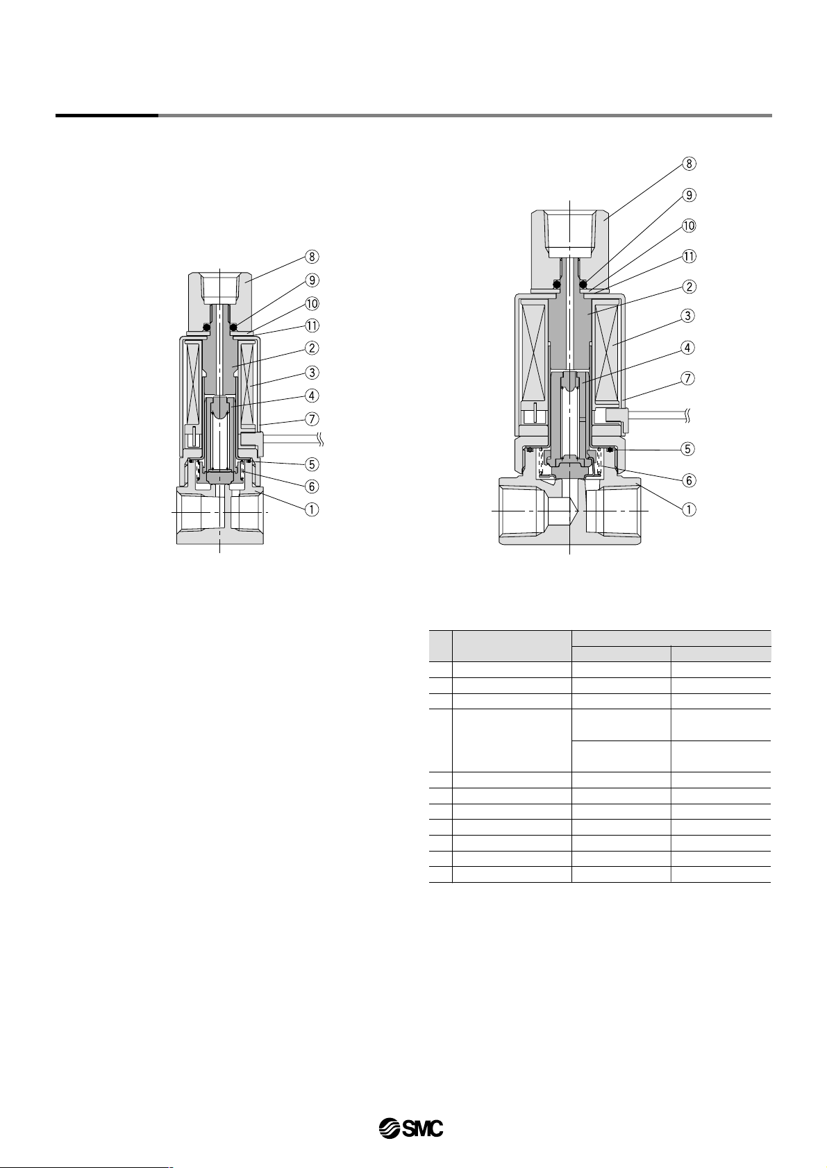
Series
VDW10/20/30
2

VDW11
VDW31
VDW21
No.
1
2
3
4
5
6
7
8
Body
Tube assembly
Coil assembly
O-ring (body)
Return spring
Cover
Clip
Description
Material
Optional
Stainless steel
—
—
FKM
—
—
—
Parts list
Standard
Brass
Stainless steel
—
NBR
Stainless steel
SPCE
Stainless steel
VDW11/21:
Stainless steel, PPS,
FKM
VDW31:
Stainless steel, FKM
VDW11/21:
Stainless steel, PPS,
NBR
VDW31:
Stainless steel, NBR
Amature assembly
Construction
3
Compact Direct Operated
2 Port Solenoid Valve for W ater and Air Series VDW10/20/30

Dimensions
VDW11 VDW21
VDW31
Lead wire
l approx. 300
2– ø3.2
21
27
14
20
20
ø17
485
11
6
4–ø5
2–ø3.5
Rectifying device
AC type
M5
1 (IN) port
2-M2.5 x 0.45
Thread depth 3.5
M5
2 (OUT) port
Lead wire
l approx. 300
Rectifying device
AC type
Lead wire
l approx. 300
Rectifying device
AC type
M5, 1/8
1 (IN) port
M5, 1/8
2 (OUT) port
1/8, 1/4
1 (IN) port
Dimensions inside ( ) are for port size 1/8.
2-M4 x 0.7
Thread depth 6
1/8, 1/4
2 (OUT) port
2-M3 x 0.5
Thread depth 5
ø20.5
54
8
15
22
5
20
27
20
27
1
SMC
66 (62.5) 6
12.8
25
34
ø28
30
40
36 (27.6)
1
SMC
8.5 (6.3)
1
1
VDW 0 15A 12
1
2
10
20
Series
Bracket assembly part no.
Types
10, 20
VCW20 12 01A
Type 30
Series
VDW10/20/30
4

How to Order Valves (for Manifold)
Manifold Options
How to Order Manifolds
VV2DW 2 05 01
How to Order Manifold Assemblies (Example)
Enter the valve and option models to be mounted
under the manifold base part number.
<Example>
VV2DW2-0501 ……...
∗VDW23-5G-2 ………...
1 set Manifold part no.
5 sets Valve part no.
(Stations 1 to 5)
Enter together in
order, counting
from station 1
on the D side.
1
2
3
10
20
30
Series
Materials
Nil
F
N
Rc
G
NPT
Thread type
Nil
F
None
With bracket
Option
Symbol
M5
01
02
Port
size
M5
1/8 (6A)
1/4 (8A)
10
—
—
Series
20
—
30
Note) IN port sizes are as follows.
10: 1/8 (6A)
20: 1/4 (8A)
30: 3/8 (10A)
OUT port size
Stations
VVDW 0 3A2
1
2
10
20
Series
Materials
VDW 2 35 2G
1
2
3
10
20
30
Series
3
N.C. for Manifold
Valve type
1
2
3
4
5
6
9
100VAC (50/60Hz)
200VAC (50/60Hz)
110VAC (50/60Hz)
220VAC (50/60Hz)
24VDC
12VDC
Other
Voltage
Symbol
Nil
A
G
H
L
Symbol
1
2
1
2
3
2
3
4
Body material
Brass
Stainless
steel
Seal material
NBR
FKM
NBR
FKM
FKM
Coil insulation
Materials and insulation type
G
Grommet
Electrical entry
Orifice size
mm
ø1
ø1.6
ø1.6
ø2.3
ø3.2
ø2
ø3
ø4
10
20
30
Series
Orifice size
Class B
Blanking plate assembly
Note)
Symbol
Nil
A
G
H
Manifold material
Brass
Stainless steel
Seal material
NBR
FKM
NBR
FKM
Symbol
G
H
Plate material
Stainless
steel
∗ Plate material is stainless steel only.
Seal material
NBR
FKM
Types 10, 20
VVCW20 3A
Materials
Symbol
Nil
A
G
H
Plate material
Brass
Stainless
steel
Seal material
NBR
FKM
NBR
FKM
Type 30
1
D side
2
3
4
5
U side
02
:
10
2 stations
:
10 stations
—
"∗" is the symbol for
mounting. Add "∗" in front
of the part numbers for
solenoid valves, etc., to
be mounted.
Note) For pure water: The armature is a corrosion
resistant construction.
Note) Type 30 is available
only with bracket.
5
Compact Direct Operated
2 Port Solenoid Valve for W ater and Air Series VDW10/20/30

Dimensions
2
35
45
52
2 stns. x 1
Dimensions
L1
L2
L3
L dimensions
3
52.5
62.5
69.5
3 stns. x 1
4
70
80
87
2 stns. x 2
5
87.5
97.5
104.5
2 stns. + 3 stns.
6
105
115
122
3 stns. x 2
7
122.5
132.5
139.5
2 stns. x 2 + 3 stns.
8
140
150
157
2 stns. + 3 stns. x 2
9
157.5
167.5
174.5
3 stns. x 3
10
175
185
192
2 stns. x 2 + 3 stns. x 2
(mm)
n (stations)
Manifold composition
Note) Manifold bases are composed by connecting 2 station and 3 station bases.
Refer to pages 9 and 10 regarding manifold additions.
VV2DW1
4-M3 x 0.5
8.1
n-M5 x 0.8
(OUT port)
L1
L3
L2
13.4
3.4
1
R1.7
16.3
2-∗1/8 (IN port)
(∗: Thread type)
16
VDW13-*G-*VDW13-*G-*VDW13-*G-*VDW13-*G-
*
1
D side
2345
n
U side
8.8 P = 17.5
8.8
(19.6)
11.57.7
(16.3)
5
7.7 11.5
61
7.7 P = 17.5
1.5
13
19.6
24.4
2.8
22.5
40 7.5
26.5
(2.8)
34
(4.4)
9.4 Approx. 300
30
(1.5)
Stations
∗ When not equipped with bracket,
the M3 threads at both ends (4
positions) can be used for other
purposes.
Series
VDW10/20/30
6

Dimensions
2
44
53
62
2 stns. x 1
Dimensions
L1
L2
L3
L dimensions
3
66
75
84
3 stns. x 1
4
88
97
106
2 stns. x 2
5
110
119
128
2 stns. + 3 stns.
6
132
141
150
3 stns. x 2
7
154
163
172
2 stns. x 2 + 3 stns.
8
176
185
194
2 stns. + 3 stns. x 2
9
198
207
216
3 stns. x 3
10
220
229
238
2 stns. x 2 + 3 stns. x 2
(mm)
2-∗1/4 (IN port)
(∗: Thread type)
n-M5 x 0.8
n-∗1/8
(OUT port)
4-M4 x 0.7
n (stations)
Manifold composition
Note) Manifold bases are composed by connecting 2 station and 3 station bases.
Refer to pages 9 and 10 regarding manifold additions.
10 24
10
46
119.5
11
9.5
( 19.5)
632
6
54
L1
L2
L3
11
Approx. 300
16
4.6
24
33
R2.3
9
4.5
19.5
11
P = 22
11
1.5
4.5
68
21
15 ( 25.5)
1
31.5
VDW23-*G-*VDW23-*G-*VDW23-*G-*VDW23-*G-*
1
Stations
D side
2345
n
U side
18.5
1
(19.5)
VV2DW2
∗ When not equipped with bracket, the M3
threads at both ends (4 positions) can be
used for other purposes.
7
Compact Direct Operated
2 Port Solenoid Valve for W ater and Air Series VDW10/20/30

2
69
81
93
2 stns. x 1
Dimensions
L1
L2
L3
Manifold composition
L dimensions
3
103.5
115.5
127.5
3 stns. x 1
4
138
150
162
2 stns. x 2
5
172.5
184.5
196.5
2 stns. + 3 stns.
6
207
219
231
3 stns. x 2
7
241.5
253.5
265.5
2 stns. x 2 + 3 stns.
8
276
288
300
2 stns. + 3 stns. x 2
9
310.5
322.5
334.5
3 stns. x 3
10
345
357
369
2 stns. x 2 + 3 stns. x 2
(mm)
n (stations)
Note) Manifold bases are composed by connecting 2 station and 3 station bases.
Refer to pages 9 and 10 regarding manifold additions.
VV2DW3
1
Stations
D side
2345n
U side
2
5.5 21
5.5 10.5
(26.5)
23
L1
L2
L3
2.5
28
4.5
(24.5)
38
20 14.7
Approx. 300
24.5
2-∗3/8 (IN port)
(∗:
Thread type)
16
VDW33-*G-
*
VDW33-*G-
*
VDW33-*G-
*
VDW33-*G-
*
P = 34.5
83
34
n-∗1/8
n-∗1/4
(OUT port)
R2.25
17.25
17.25
49
Dimensions
Series
VDW10/20/30
8

Bracket assembly Passage pipe assembly
2 station manifold base
3 station manifold base
Bracket assembly
Manifold Exploded View
Connecting
plate assembly
Connecting
plate assembly
∗ Figure shows VV2DW2.
Manifold additions
1
2
3
Install a passage pipe assembly in between the manifold bases to be added.
Connect the respective manifold bases with a connecting plate assembly. (Tightening torque: 0.9±0.1N⋅ m)
Attach brackets to the manifold bases. {when equipped with brackets} (Tightening torque: 0.9±0.1N⋅ m)
Note) Manifold station additions can be made in units of 2 or 3 stations.
Order one set each of manifold base, connection plate assembly and passage pipe assembly.
9
Compact Direct Operated
2 Port Solenoid Valve for W ater and Air Series VDW10/20/30

VVDW
<Manifold bases>
Material
02C 1 012
C
S
Brass
Stainless steel
Stations
1
2
For 2 stations
For 3 stations
OUT port size
Symbol
M5
01
Port size
M5
1/8 (6A)
1210
20
Series
1210
20
Series
VVDW
<Connecting plate assembly>
20 4A
Types 10, 20
VVCW20
Material
2C 1 01
C
S
Brass
Stainless steel
Stations
1
2
For 2 stations
For 3 stations
OUT port size
Symbol
01
02
Port size
1/8 (6A)
1/4 (8A)
Type 30
Types 10, 20
VVCW20-4A
Type 30
1210
20
Series
VVDW
<Bracket assembly>
20 5A
Types 10, 20
VVCW20-5A
Type 30
Note) Consists of a set for the D and U sides.
Note) Two sets of connecting plate and mounting screws.
∗ Type 10 is M5 only.
1210
20
Series
VVDW
<Passage pipe assembly>
2
Materials
06A
VVCW20 6A
Types 10, 20
Type 30
Symbol
Nil
A
G
H
Pipe material
Brass
Stainless
steel
Seal material
NBR
FKM
NBR
FKM
Materials
Symbol
Nil
A
G
H
Pipe material
Brass
Stainless
steel
Seal material
NBR
FKM
NBR
FKM
Nil
F
N
Rc
G
NPT
Thread type
Nil
F
N
Rc
G
NPT
Thread type
Series
VDW10/20/30
10

How to Order Valves (Single Type)
For water,
air and vacuum
2
3
200
300
Series
VDW 2 50 1 G 2 01
Nil
F
None
Foot type bracket
Option
Nil
F
N
Rc
G
NPT
Thread type
Symbol
M5
01
02
Port size
M5
1/8 (6A)
1/4 (8A)
200
—
300
—
Port size
1
2
2
3
4
Symbol
N.C.
Orifice size
mm
ø1
ø1.6
ø2
ø3
ø4
N.O.
Orifice size
mm
ø1
ø1.8
Series
200
300
Orifice size
Symbol
Nil
A
G
H
L
Body material
Coil insulation
Seal material
NBR
FKM
NBR
FKM
FKM
Brass
Class B
Stainless
steel
Materials and insulation type
1
2
3
4
5
6
100VAC (50/60Hz)
200VAC (50/60Hz)
110VAC (50/60Hz)
210VAC (50/60Hz)
24VDC
12VDC
Voltage
50
C.O.
Valve type
Electrical entry
∗ Consult SMC regarding other voltages.
G – Grommet
Note) Foot brackets are packed with valves.
Note)
Series
N.C.
(2)
N.O.
(3)
(1)
IN
Note) For pure water: The armature assembly is a
corrosion resistant construction.
11
Compact Direct Operated
3 Port Solenoid Valve for Water and Air
Series VDW200/300

Standard Specifications
Characteristic Specifications
VDW200
VDW300
Model
ø1
ø1.6
ø2
ø3
ø4
0.9
0.7
0.8
0.4
0.2
0.54 (0.03)
1.2 (0.07)
2.8 (0.16)
5.0 (0.28)
8.0 (0.44)
0.3
0.1
0.2
0.1
0.05
Orifice
size
mm
Weight
kg
Port size
M5
1/8 (6A)
1/8 (6A)
1/4 (8A)
0.12
0 to 1.0
1/8: 0.27
1/4: 0.30
Note 2)
Note 1) Effective area is for the case when IN is normally closed (N.C.).
Note 2) Indicates the maximum operating pressure differential of pressure ports 2 and 3.
Note 3) The maximum operating pressure differential changes depending on the flow direction of the fluid.
Refer to page 21 for details.
Note 4) For low vacuum specifications, the operating pressure range is 1Torr (1.33 x 10
²Pa) to 1.0MPa.
Consult SMC if used below 1Torr (1.33 x 10
²Pa).
Valve specifications
Coil
specifications
Valve construction
Fluid
Note 2)
Withstand pressure MPa
Ambient temperature °C
Fluid temperature °C
Environment
Valve leakage cm
3
/min
Mounting orientation
Vibration/Impact m/s
2
Note 4)
Rated voltage
Allowable voltage fluctuation %
Coil insulation type
Enclosure
Note 5)
Power consumption W
Note 3)
Maximum operating
pressure
differential MPa
Note 3)
Effective area
mm²
(Cv factor)
Note 1)
Operating
pressure
range
MPa
Note 4)
Pressure port 1
Pressure ports 2, 3
Direct operated poppet
Water (except waste water or agricultural water), Air, Low vacuum
2.0
–10 to 50
1 to 50 (with no freezing)
Location without corrosive or explosive gases
0 (with water pressure)
Unrestricted
30/150
24VDC, 12VDC, 100VAC, 110VAC, 200VAC, 220VAC (50/60Hz)
±10% of rated voltage
Class B
Dust proof (equivalent to IP40)
3
Note 1) Consult SMC when used under conditions which may cause condensation on the exterior of the product.
Note 2) When used with pure water, select "L" (stainless steel, FKM) for the material type.
Note 3) Since AC coil specifications include a rectifying device, there is no difference in power consumption for starting
and holding.
3.5W in case of 110/220VAC.
Note 4) Vibration resistance …No malfunction when tested with one sweep of 5 to 200Hz in the axial direction and at a
right angle to the armature, in both energized and deenergized states.
Impact resistance ….. No malfunction when tested with a drop tester in the axial direction and at a right angle to
the armature, one time each in energized and deenergized states.
Note 5) Consult SMC regarding drip-proof specifications (equivalent to IP54) .
Series
VDW200/300
12
Construction
VDW250
VDW350
No.
1
2
3
4
5
6
7
8
9
10
11
Body
Tube assembly
Coil assembly
O-ring (body)
Return spring
Cover
Socket
O-ring
Plate
Wave washer
Description
Material
Optional
Stainless steel
—
—
FKM
—
—
Stainless steel
FKM
—
—
Parts list
Standard
Brass
Stainless steel
—
NBR
Stainless steel
SPCE
Brass
NBR
SPCC
Stainless steel
VDW250:
Stainless steel, PPS,
FKM
VDW350:
Stainless steel, FKM
VDW250:
Stainless steel, PPS,
NBR
VDW350:
Stainless steel, NBR
Amature assembly
13
Compact Direct Operated
3 Port Solenoid Valve for Water and Air Series VDW200/300

Dimensions
VDW250 VDW350
Lead wire
l approx. 300
2–ø3.5
4–ø5
Rectifying device
AC type
M5, 1/8
1 (IN) port
1/8, 1/4
1 (IN) port
2-M3
Thread depth 5
M5, 1/8
2 (N.C.) port
Lead wire
l approx. 300
Rectifying device
AC type
M5, 1/8
3 (N.O.) port
1/8, 1/4
3 (N.O.) port
1/8, 1/4
2 (N.C.) port
2-M4 x 0.7
Thread depth 6
ø20.5
22
69
8
5
15
20
27
20
27
1
SMC
6
12.8
25
34
ø28
30
40
36 (27.6)
1
SMC
Dimensions inside ( ) are for port size 1/8.
86 (82.5)
8.5 (6.3)
3
3
1
VDW20 15A 1
Bracket part no.
Type 200
VCW20 12 01A
Type 300
Series
VDW200/300
14

For air
For water
How to find the flow rate for water
• Formula based on Cv factor
Q = 14.2⋅ Cv⋅ 10.2⋅ ∆P … l/min
• Formula based on effective area (Smm²)
Q = 0.8⋅ S⋅ 10.2⋅ ∆P …… l/min
How to find the flow rate for air
1. For subsonic range
Where P1 + 0.1013 = (1 to 1.8941) (P2 + 0.1013)
• Formula based on Cv factor
Q = 4073.4⋅Cv⋅ ∆P (P2 + 0.1013) … l/min (ANR)
• Formula based on effective area
Q = 226.3⋅S⋅ ∆P (P2 + 0.1013) …… l/min (ANR)
2. For sonic range
Where P1 + 0.1013≥1.8941 (P2 + 0.1013)
• Formula based on Cv factor
Q = 1972.8⋅ Cv⋅ (P1 + 0.1013) … l/min (ANR)
• Formula based on effective area
Q = 109.6⋅S⋅ (P1 + 0.1013) ….… l/min (ANR)
Q: Flow rate (l/min), ∆P: Pressure differential (P1—P2), P1: Upstream pressure (MPa)
P2: Downstream pressure (MPa), S: Effective area (mm²), Cv: Cv factor
100
10
5.0
1.0
0.1
0.001 0.01 0.1 1 10
Pressure differential ∆P = (P
₁ – P₂)
MPa
Flow rate Ql /min
1. Materials
NBR: Nitrile rubber
FKM: Fluoro rubber – Trade names: Viton®, Dai-el, etc.
Other
Viewing
the graph
VDW30 ø2 CV = 0.16ø2 CV = 0.16
VDW20 ø2.3 CV = 0.18ø2.3 CV = 0.18
VDW30 ø4 CV = 0.39ø4 CV = 0.39
VDW20 ø3.2 CV = 0.3ø3.2 CV = 0.3
VDW30
ø2 CV = 0.16
VDW10 ø1 CV = 0.03ø1 CV = 0.03
VDW VDW
ø1.6 CV = 0.07ø1.6 CV = 0.07
10
20
VDW10
ø1 CV = 0.03
VDW
ø1.6 CV = 0.07
10
20
VDW20
ø2.3 CV = 0.18
VDW30 ø3 CV = 0.28ø3 CV = 0.28VDW30
ø3 CV = 0.28
VDW30
ø4 CV = 0.44
VDW20
ø3.2 CV = 0.3
The sonic range pressure to generate a flow rate of 300l/min (ANR)
for orifice ø2.3 (VDW20) is P1 approx. 0.77MPa,
for orifice ø3 (VDW30) is P1 approx. 0.45MPa,
for orifice ø4 (VDW30) is P1 approx. 0.24MPa.
Viewing
the graph
Explanation of Terminology
Pressure Terminology
1. Maximum operating pressure differential
This indicates the maximum pressure differential (upstream
and downstream pressure differential) which can be allowed
for operation with the valve closed or open. When the
downstream pressure is 0MPa, this becomes the maximum
operating pressure.
2. Maximum operating pressure
This indicates the limit of pressure that can be applied inside
the pipelines. (line pressure)
(The pressure differential of the solenoid valve unit must be no
more than the maximum operating pressure differential.)
3.
Withstand pressure
The pressure which must be withstood without a drop in
performance after returning to the operating pressure range.
(the value under the prescribed conditions)
Electrical Terminology
1. Surge voltage
A high voltage which is momentarily generated in the shut-off unit
by shutting off the power.
To generate a water flow of 4l/min at a differential pressure of
0.1MPa, an effective area with Cv factor 0.28 (VDW30ø3) or
more is required.
0.1
0.2
0.3
0.4
0.5
0.6
0.7
0.8
0.9
1.0
0
.95
0.95
0
.90.9
0.850.85
0.80.8
0
.7
5
0.75
0.70.7
0.650.65
0.60.6
0.5
5
0.55
0.50.5
0.30.3
0.250.25
0.20.2
0.10.1
0.050.05
0
.95
0
.9
0.85
0.8
0
.7
5
0.7
0.65
0.6
0.5
5
0.5
0.450.450.45
0.40.40.4
0.350.350.35
0.3
0.25
0.2
0.150.150.15
0.1
0.05
S = 0.54
S = 1.2
S = 3.2
S = 5.8
S = 2.8
S = 5.0
S = 8.0
VDW10ø1
VDW ø1.6
VDW20ø2.3
VDW20ø3.2
VDW30ø2
VDW30ø3
VDW30ø4
6050403020
1251007550
10
35030025020015010050
600500400300200100
30025020015010050
600500
400300200100
900800700
600500400300200
10
20
Downstream pressure of valve (P2) MPa
Upstream pressure of valve P
₁ = 1.0MPa
Critical
pressure
Subsonic
Sonic
Flow rate Q l/min (ANR)
Series VDW
Model Selection
15

Series VDW
Safety Instruction s
These safety instructions are intended to prevent a hazardous situation and/or
equipment damage. These instructions indicate the level of potential hazard by a
label of "Caution", "Warning" or "Danger". To ensure safety, be sure to observe
ISO 4414
Note 1)
and other safety practices.
1. The compatibility of equipment is the responsibility of the person who designs
the system or decides its specifications.
Since the products specified here are used in various operating conditions, their compatibility for the
specific system must be based on specifications or after analysis and/or tests to meet your specific
requirements. Be particularly careful in determining the compatibility of the fluid to be used.
2. Only trained personnel should operate machinery and equipment.
The fluid can be dangerous if handled incorrectly. Assembly, handling or repair of systems should be
performed by trained and experienced operators.
3. Do not service machinery/ equipment or attempt to remove components until
safety is confirmed.
1. Inspection and maintenance of machinery/equipment should only be performed after confirmation of safe
locked-out control positions and measures to prevent danger from the fluid.
2. When equipment is to be removed, confirm the safety process as mentioned above and be certain there
is no danger from fluid leakage or fluid remaining in the system.
3. Restart machinery carefully, confirming that safety measures are being implemented.
4. Contact SMC if the product is to be used in any of the following conditions:
1. Conditions and environments beyond the given specifications, or if product is used outdoors.
2. With fluids whose application causes concern due to the type of fluid or additives, etc.
3. An application which has the possibility of having negative effects on people, property, or animals,
requiring special safety analysis.
Note 1) ISO 4414 : Pneumatic fluid power -- Recommendations for the application of equipment to transmission and control
systems
Warning
Cauti on :
Operator error could result in injury or equipment damage.
Warning
:
Operator error could result in serious injury or loss of life.
Danger :
In extreme conditions, there is a possible result of serious injury or loss of life.
16

1. Confirm the specifications.
Give careful consideration to operating conditions such as the
application, fluid and environment, and use within the operating
ranges specified in this catalog.
2. Fluid temperature
Operate within the prescribed fluid temperature range.
3. Fluid quality
For water
The use of fluid which contains foreign matter can cause
problems such as malfunction and seal failure by promoting
wear of the valve seat and core, and by sticking to the sliding
parts of the armature, etc. Install a suitable filter (strainer)
immediately upstream from the valve. As a general rule, use 80
to 100 mesh.
For air
Use general purpose compressed air (except dry air) and
provide a filter of 40µm or less in the upstream piping.
2. Low temperature operation
1. The valve can be used at ambient temperatures as low as
–10°C, but take measures to prevent freezing or
solidification of impurities, etc.
2. When used in cold areas with water, etc., adopt freeze
prevention measures such as draining the water from
pipelines after pump operation has been stopped. If
warmed with a heater, etc., avoid the coil unit. Also,
implement warming or other freeze prevention measures
for the body.
OFF
CR
1. Cannot be used as an emergency shutoff
valve, etc.
The valves presented in this catalog are not designed for safety applications such as an emergency shutoff valve. If the
valves are used in this type of system, other reliable safety assurance measures should also be adopted.
2. Extended periods of continuous energization
Consult SMC if valves will be continuously energized for extended periods of time.
3. Liquid seals
In cases with a flowing liquid, provide a by-pass valve in the
system to prevent the liquid from entering the liquid seal circuit.
4. This solenoid valve cannot be used for explosion protection.
5. Maintenance space
The installation should allow sufficient space for maintenance
activities (removal of valve, etc.).
Warning
Precautions on Design Selection
Warning
Caution
1. Leakage voltage
Particularly when using a resistor in parallel with a switching
element and using a C-R element (surge voltage suppressor)
to protect the switching element, take note that leakage current
will flow through the resistor and C-R element, etc., creating a
danger that the valve may not shut OFF.
Switching element
Leakage voltage
Valve
Leakage current
Power supply
10% or less of rated voltage
AC coil
2% or less of rated voltage
DC coil
Series VDW
2/3 Port Solenoid Valve for Fluid Control/Precautions 1
Be sure to read before handling.
17

1. If air leakage increases or equipment does
not operate properly, stop operation.
After mounting is completed, confirm that it has been done
correctly by performing a suitable function test.
2. Do not apply external force to the coil
section.
When tightening is performed, apply a wrench or other tool to
the outside of the piping connection parts.
3. Do not warm the coil assembly with a heat
insulator, etc.
Use tape and heaters, etc., for freeze prevention on the piping
and body only. They can cause the coil to burn out.
4. Secure the product except in the case of steel
piping and copper fittings.
5. Avoid sources of vibration, or set the arm
from the body to the minimum length so that
resonance will not occur.
6. Instruction manual
Mount the product after reading the manual carefully and
understanding its contents. Also keep the manual where it can
be referred to as necessary.
7. Painting and coating
Warnings and specifications printed or pasted on the product
should not be erased, removed or covered up.
Mounting
Warning
1. Preparation before piping
Before piping is connected, it should be thoroughly blown out
with air (flushing) or washed to remove chips, cutting oil and
other debris from inside the pipe.
2. Wrapping of pipe tape
When connecting pipes and fittings, etc., be sure that chips from
the pipe threads and sealing material do not get inside the
valve.
Furthermore, when pipe tape is used, leave 1.5 to 2 thread ridges exposed at the end of the threads.
3. Avoid connection of ground lines to piping,
as this may cause electric corrosion of the
system.
4. Always tighten threads with the proper
tightening torque.
When screwing fittings into valves, tighten with the proper tightening torque as shown below.
Piping
Caution
5. Connection of piping to the product
When connecting piping to the product, refer to its instruction
manual to avoid mistakes regarding the supply port, etc.
Winding
direction
Pipe tape
Expose approx. 2 threads
Connection threads
M5
Rc 1/8
Rc 1/4
Rc 3/8
1.5 to 2
7 to 9
12 to 14
22 to 24
∗ Reference
Tightening of M5 fitting threads
After tightening by hand, tighten approximately 1/6 turn further with a tightening
tool. However, when using miniature fittings, tighten an additional 1/4 turn after
tightening by hand. (In cases where there is a gasket in two places such as a
universal elbow or universal tee, double the additional tightening to 1/2 turn.)
Proper tightening torque N⋅m
Tightening torque for piping
Series VDW
2/3 Port Solenoid Valve for Fluid Control/Precautions 2
Be sure to read before handling.
18

Wiring
DC circuit AC circuit
1 (+)
2 (–)
SOL. SOL.
1
2
Caution
Rectifying device
ZNR
Operating Environment
1. Perform maintenance in accordance with the
procedures in the instruction manual.
Improper handling can cause damage or malfunction of equipment and devices, etc.
2. Demounting of the product
1. Shut off the fluid supply and release the fluid pressure in the
system.
2. Shut off the power supply.
3. Demount the product.
3. Low frequency operation
Switch valves at least once every 30 days to prevent
malfunction. In addition, perform maintenance inspections once
every six months to ensure optimum performance.
Warning
1. Filters and strainers
1. Be careful regarding clogging of filters and strainers.
2. Replace filter elements after one year of use, or earlier if the
amount of pressure drop reaches 0.1MPa.
3. Clean strainers when the amount of pressure drop reaches
0.1MPa.
4.
Flush drainage from filters periodically.
2. Storage
In case of long term (approx. one month or more) storage after
use with water, first thoroughly remove all moisture to prevent
rust and deterioration of rubber materials, etc.
Caution
1. As a rule, use electrical wire of 0.5 to
1.25mm² or more.
Furthermore, do not allow excessive force to
be applied to the lines.
2. Use electrical circuits which do not generate
chattering in their contacts.
3. Use voltage which is within ±10% of the rated
voltage. In cases of a DC power supply where
emphasis is placed on responsiveness, stay
within ±5% of the rated value. The voltage
drop is the value in the lead wire section connecting the coil.
Caution
Electrical Connections
Caution
Rated voltage
DC
100VAC
200VAC
Other AC
Black
Blue
Red
Gray
Red
Blue
Red
Gray
Lead wire color
∗ DC does not have polarity.
1 ( )
2 ( )
Electrical Circuits
1. Do not use valves in atmospheres of corrosive
gases, chemicals, salt water, water or steam, or
where there is direct contact with same.
2. Do not use in explosive atmospheres.
3. Do not use in locations subject to vibration or
impact.
4. Do not use in locations where radiated heat will be
received from nearby heat sources.
5. Employ suitable protective measures in locations
where there is contact with water droplets, oil or
welding spatter, etc.
Warning
Maintenance
Series VDW
2/3 Port Solenoid Valve for Fluid Control/Precautions 3
Be sure to read before handling.
19

Replacement of the Solenoid Coil
Caution
Clip
Cover
Cover
Flat head screw driver
2 port valve 3 port valve
Tube assembly
Socket
O-ring
Plate
Wave washer
Cover
Coil assembly
Fixed armature threads
Coil assembly
Push the clip in direction (1) with
a flat head screw driver, etc.,
and remove it from the tube
assembly groove.
1
2
3
Remove the cover in direction (2),
and replace the coil assembly.
In case of types 10 and 30, the
cover alone cannot be removed
because it is integrated with the
coil assembly.
After replacing the coil, insert the
clip into the tube assembly
groove from direction (3). After
inserting it into the groove,
confirm the position and condition
of the clip.
Tube assembly groove
Center of clip
OK NG
Inserted position
Inserted condition
After removing the socket with a wrench, etc., lift off the plate, wave
washer and cover, and replace the coil assembly. After replacing the
coil, first tighten the socket by hand while holding down the plate and
wave washer, and then tighten it further with a torque of 0.8 to 1N⋅ m .
∗ Precautions when attaching and removing the socket
• Be careful that the O-ring installed on the bottom (plate side) of the socket does
not fall out or become chewed up, etc.
• Be sure to hold the body with a wrench, etc., and tighten the socket within the
tightening torque range given above. If excessive torque is applied, there is a
danger of damaging the threads.
Note
In case of type 300, the cover
alone cannot be removed because
it is integrated with the coil
assembly.
Note
Series VDW/Specific Product Precautions 1
Be sure to read before handling.
Refer to pages 16 through 19 for safety instructions and precautions for 2/3 port solenoid valve for
fluid control.
20

Replacement Parts Fluid Flow Direction
Solenoid coil part numbers
1
2
3
10
20, 200
30, 300
Series
VDW
Nil
L1
Note)
300mm
600mm
Lead wire length
1
2
3
4
5
6
100VAC
200VAC
110VAC
220VAC
24VDC
12VDC
Voltage
B
C1
C2
20, 200
10, 30
300
Type
Note 1)
Clip part numbers (2 port)
AZ-T-VDW
How to Order Valves
(Refer to pages 1, 5 and 11.)
01B1
Note) Type L1 is optional.
2
3
10, 20
30
Series
VDW 20 102
Piping to 3 Port Valve N.O. Port
Caution
Socket
Cover
When piping to an N.O. port, be sure to perform piping work
while holding the socket with a wrench or other tool. Refer to
page 18 for other precautions related to piping.
Caution
The maximum operating pressure differential differs depending
on the flow direction of the fluid. If the pressure differential at
each port exceeds the values in the table below, valve
leakage may occur.
Model
VDW10
VDW20
VDW30
ø1
ø1.6
ø1.6
ø2.3
ø3.2
ø2
ø3
ø4
Orifice size
mm
Maximum operating pressure
differential MPa
Pressure port 1
0.9
0.4
0.7
0.4
0.2
0.8
0.4
0.2
Pressure port 2
Note 1)
0.4
0.2
0.2
0.1
0.05
0.2
0.1
0.05
2 port valve
Note) When applying pressure from port 2, be careful to avoid vibration and impacts, etc.
OUT
(2)
(1)
IN
Model
VDW200
VDW300
ø1
ø1.6
ø2
ø3
ø4
Orifice size
mm
Maximum operating pressure
differential MPa
Pressure port 1
0.9
0.7
0.8
0.4
0.2
Pressure ports 2, 3
Note 1 & 2)
0.3
0.1
0.2
0.1
0.05
3 port valve
N.C.
(2)
N.O.
(3)
(1)
IN
2
Note 1) In case of a type C coil (for 10, 30, 300), the cover will be an integrated
type.
To have a label on the cover, enter the part number below together with
the coil part number.
Note 1) Indicates the maximum operating pressure differential for pressure ports 2 and 3.
Note 2) When the port 2 pressure is the higher pressure, be careful to avoid vibration and
impacts, etc.
21
Series VDW/Specific Product Precautions 2
Be sure to read before handling.
Refer to pages 16 through 19 for safety instructions and precautions for 2/3 port solenoid valve for
fluid control.

EUROPE
SPAIN/PORTUGAL
SMC España, S.A.
SWEDEN
SMC Pneumatics Sweden AB
SWITZERLAND
SMC Pneumatik AG.
UK
SMC Pneumatics (U.K.) Ltd.
ASIA
CHINA
SMC (China) Co., Ltd.
HONG KONG
SMC Pneumatics (Hong Kong) Ltd.
INDIA
SMC Pneumatics (India) Pvt. Ltd.
MALAYSIA
SMC Pneumatics (S.E.A.) Sdn. Bhd.
PHILIPPINES
SMC Pneumatics (Philippines), Inc.
SINGAPORE
SMC Pneumatics (S.E.A.) Pte. Ltd.
SOUTH KOREA
SMC Pneumatics Korea Co., Ltd.
TAIWAN
SMC Pneumatics (Taiwan) Co., Ltd.
THAILAND
SMC Thailand Ltd.
NORTH AMERICA
CANADA
SMC Pneumatics (Canada) Ltd.
MEXICO
SMC Corporation (Mexico) S.A. de C.V.
USA
SMC Pneumatics, Inc.
SOUTH AMERICA
ARGENTINA
SMC Argentina S.A.
BOLIVIA
SMC Pneumatics Bolivia S.R.L.
BRAZIL
SMC Pneumaticos Do Brazil Ltda.
CHILE
SMC Pneumatics (Chile) S.A.
VENEZUELA
SMC Neumatica Venezuela S.A.
OCEANIA
AUSTRALIA
SMC Pneumatics (Australia) Pty. Ltd.
NEW ZEALAND
SMC Pneumatics (N.Z.) Ltd.
EUROPE
AUSTRIA
SMC Pneumatik GmbH
CZECH
SMC Czech s.r.o.
DENMARK
SMC Pneumatik A/S
FINLAND
SMC Pneumatiikka OY
FRANCE
SMC Pneumatique SA
GERMANY
SMC Pneumatik GmbH
HUNGARY
SMC Hungary Kft.
IRELAND
SMC Pneumatics (Ireland) Ltd.
ITALY
SMC Italia S.p.A.
NETHERLANDS
SMC Pnuematics BV.
NORWAY
SMC Pneumatics Norway A/S
ROMANIA
SMC Romania s.r.l.
RUSSIA
SMC Pneumatik LLC.
SLOVAKIA
SMC Slovakia s.r.o.
SLOVENIA
SMC Slovenia d.o.o.
SMC'S GLOBAL MANUFACTURING, DISTRIBUTION AND SERVICE NETWORK
1-16-4 Shimbashi, Minato-ku, Tokyo 105-0004, JAPAN
Tel: 03-3502-2740 Fax: 03-3508-2480
URL http://www.smcworld.com
© 1999 SMC CORPORATION All Rights Reserved
Specifications are subject to change without prior notice
and any obligation on the part of the manufacturer.
Printed in Japan.
1st printing December, 1999 D-SMC.L.A. P-80 (D)
 Loading...