

SMC Networks ZSE3,ISE3L,ISE3 Operation Manuals
The set data has changed unexpectedly.
Press the RESET button and set all
data again.
Piping
Piping connection
Connect the piping to the pressure switch with a plug or fitting.
The tightening torque of the piping port must be 8.8 Nm or less.
Error display Error type Troubleshooting method
Load on OUT1 has a short-circuit or an overcurrent
has occurred.
Turn off the power supply and
replace the load connected to
OUT1 (black wire).
Load on OUT2 has a short-circuit or an overcurrent
has occurred.
Compared with the ambient pressure, ±0.07 MPa (in
case of 1 MPa use) or ±7 kPa or more (in case of
vacuum use or 100 kPa use) has been applied during
zero clear.
Turn off the power supply and
replace the load connected to
OUT2 (white wire).
Reduce the pressure to 0.5 MPa or
less. (In case of positive pressure,
reduce the pressure to the rated
pressure or less.)
Pressure exceeding 0.5 MPa has been applied.
(In case of positive pressure, pressure exceeding the
rated pressure has been applied.)
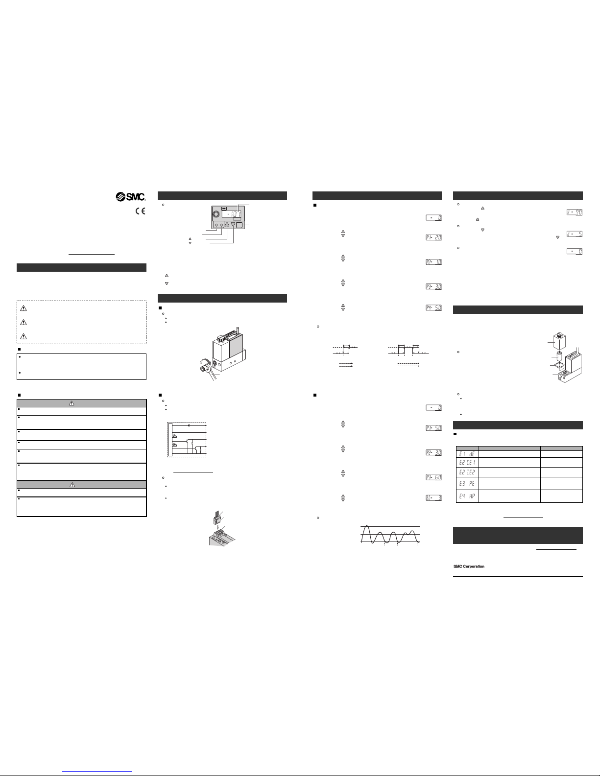
RESET SET
kPa
LCD
R
ESET button
SET button
LED
button (UP)
button (DOWN)
RESET button: Resets after an error or to zero clear the display.
SET button: Press this button to change to another mode and to set a value.
LCD: Displays pressure value, setting mode, and error code.
LED: The green LED is ON when output OUT1 is ON. The red LED is ON
when output OUT2 is ON. When both OUT1 and OUT2 are ON, both the
green and red LEDs will be ON. When an error occurs, the red LED
flashes.
button (UP): Selects the peak display mode or increases the ON/OFF set
value.
button (DOWN): Selects the bottom display mode or decreases the
ON/OFF set value.
Wiring
Connection
Connections should only be made with the power supply turned off.
Incorrect wiring will lead to digital pressure switch breakdown, failure or
malfunction. So be sure to confirm the wire colour and terminal number
before wiring.
Spanner
Connector
Connecting / Disconnecting
When mounting the connector, insert it straight into the socket, holding the
lever and connector body, and push the connector until the lever hooks into
the housing, and locks.
When removing the connector, press down the lever to release the hook
from the housing and pull the connector straight out.
Connector
Lever
Pins
2-output type
1
. Set value input mode
Press the "SET" button to display "P1-20"
∗
1
.
The output OUT1(1) set value input mode is selected.
∗1: The set value of P1 is -20
•Hysteresis mode
(P1≥P2, P3≥P4)
After adjusting the pressure to the
ambient pressure, perform RESET
operation.
2. OUT1(1) set value input
Pressing the button increases the set value.
Pressing the button decreases the set value.
Press the "SET" button to set the value and select the output
O
UT1(2) set value input mode.
The set value of P2 is displayed.
5. OUT2(2) set value input
Pressing the button increases the set value.
Pressing the button decreases the set value.
Press the "SET" button to set the value and exit this mode.
∗
: P1: Set value for OUT1(1) P2: Set value for OUT1(2)
P3: Set value for OUT2(1) P4: Set value for OUT2(2)
3. OUT1(2) set value input
Pressing the button increases the set value.
Pressing the button decreases the set value.
Press the "SET" button to set the value and select the output
OUT1(1) set value input mode.
The set value of P3 is displayed.
4. OUT2(1) set value input
Pressing the button increases the set value.
Pressing the button decreases the set value.
Press the "SET" button to set the value and select the output
OUT2(2) set value input mode.
The set value of P4 is displayed.
Output method
•Window comparator mode
(P1<P2, P3<P4)
(Hysteresis = 3 digits fixed)
P1
(P3)P2(P4)
OFF
ON
Hysteresis
(Fixed)
Pressure low Pressure high
Vacuum low Vaccum high
Hysteresis
(Fixed)
P1
(P3)P2(P4)
OFF
ON
Hysteresis (Variable)
Pressure low Pressure high
Vacuum low Vacuum high
∗: •Hysteresis mode (same as for positive pressure use) When the value of hysteresis is set to 2 digits or less,
the switching output might chatter due to fluctuation of the input pressure around its set point.
•Window comparator mode (same as for positive pressure use) since the hysteresis will be 3 digits, separate
P1 from P2 (in case of 2-output type, same as for P3 and P4) by 7 digits or more.
∗: 1 digit is the minimum pressure display unit.
LED Green
LED Red
Main circuit
Brown[+] ..... DC(+)
Grey
.....
Black[1] ..... OUT1
White[2] ..... OUT2/Failure predictive output
Blue[-]
..... DC(-)
A
nalogue output: 1 to 5 V (±5%F.S.)
Output impedance: Approx. 1 kΩ
Digital Pressure Switch
Operation Manual
ZSE3/ISE3(L)
Thank you for purchasing an SMC ZSE3/ISE3(L) Series Digital Pressure Switch.
Please read this manual carefully before operating the product and make sure you
understand its capabilities and limitations.
Please keep this manual handy for future reference.
To obtain more detailed information about operating this product, please
refer to the SMC website (URL http:// www.smcwor ld.com
) or co ntact SMC
directl y.
Safety Instructions
These safety instructions are intended to prevent hazardous situations and/or
equipment damage.
These instructions indicate the level of potential hazard with the labels of
"Caution", "Warning" or "Danger". They are all important notes for safety and must
be followed in addition to International standards (ISO/IEC) and other safety
regulations.
CAUTION indicates a hazard with a low level of risk
which, if not avoided, could result in minor or
moderate injury.
Operator
T
his operation manual is intended for those who have knowledge of machinery
using pneumatic equipment, and have sufficient knowledge of assembly,
operation and maintenance of such equipment. Only those persons are
allowed to perform assembly, operation and maintenance.
Read and understand this operation manual carefully before assembling,
operating or providing maintenance to the product.
Caution:
Warning:
Danger:
WARNING indicates a hazard with a medium level of
risk which, if not avoided, could result in death or
serious injury.
DANGER indicates a hazard with a high level of risk
which, if not avoided, will result in death or serious
injury.
Safety Instructions
Do not disassemble, modify (including changing the printed circuit board) or repair.
An injury or failure can result.
Do not operate in an atmosphere containing flammable or explosive gases.
Fire or an explosion can result.
This product is not designed to be explosion proof.
Do not use the product in a place where static electricity is a problem.
Otherwise it can cause failure or malfunction of the system.
If using the product in an interlocking circuit:
•Provide a double interlocking system, for example a mechanical system
•Check the product regularly for proper operation
Otherwise malfunction can result, causing an accident.
The following instructions must be followed during maintenance:
•Turn off the power supply
•Stop the air supply, exhaust the residual pressure and verify that the air is released before performing
maintenance work
Otherwise an injury can result.
After maintenance is complete, perform appropriate functional inspections and leak tests.
Stop operation if the equipment does not function properly or there is a leakage of fluid.
When leakage occurs from parts other than the piping, the product might be faulty.
Disconnect the power supply and stop the fluid supply.
Do not apply fluid under leaking conditions.
Safety cannot be assured in the case of unexpected malfunction.
Do not touch the terminals and connectors while the power is on.
Otherwise electric shock, malfunction or damage to the product can result.
D
o not operate the product outside of the specifications.
Do not use for flammable or harmful fluids.
Fire, malfunction, or damage to the product can result.
Verify the specifications before use.
Warning
Caution
Summary of Product parts
Names of individual parts
Mounting and Installation
Refer to the product catalogue or SMC website
(URL http://www.smcworld.com
) for more information about wiring.
Pressure Setting
∗: The symbol shown in [ ] indicates the pin assignment of the connector.
Peak hold mode
Pressing the button when pressure is displayed enables the
upper limit peak value (value with a high degree of vacuum) to be
held. In this case, "H" is displayed on the LCD. To reset holding,
press the button again.
Bottom hold mode
Pressing the button when pressure is displayed enables the
lower limit peak value (value with low vacuum) to be held. In this
case "d" is displayed on the LCD. To reset holding, press the
button again.
Reset function
Pressing the RESET button causes the following
1. Measurement mode
•Zero clear
•
Clearing the peak hold mode or bottom hold mode
•Clearing the failure predictive function internal counter
•Resetting the failure predictive output
2. Upon error occurrence
•The data set in the setting mode is retained as is and the state when the
power supply was turned on is restored (System reset is triggered).
•In case of a data error, the setting mode is selected. When you finish
setting, the state when the power supply was turned on is restored.
(System reset is triggered).
∗: In the set value input mode, the reset function does not work.
Replacement of elements
If element clogging causes deterioration of the
adsorption force or slows the response time,
stop operation and replace the element.
Filter element part no.: ZX1-FE
Confirm that a filter gasket is seated in the
groove before reassembling the parts.
Filter gasket part no.: ZX1-FG
1-output type with the failure predictive function
1. Set value input mode
Press the "SET" button to display "P1-50"
∗
1
.
The output OUT1(1) set value input mode is selected.
∗
1: The set value of P1 is -50
2. OUT1(1) set value input
Pressing the button increases the set value.
Pressing the button decreases the set value.
Press the "SET" button to set the value and select the output
OUT1(2) set value input mode.
The set value of P2 is displayed.
5. Failure predictive count set value input
Pressing the button increases the set value.
Pressing the button decreases the set value.
Press the "SET" button to set the value and exit this mode.
∗: P1: Set value for OUT1(1) P2: Set value for OUT1(2)
P3: Set value for failure predictive pressure EC: Set value for failure predictive count
3. OUT1(2) set value input
Pressing the button increases the set value.
Pressing the button decreases the set value.
Press the "SET" button to set the value and select the failure
predictive pressure set value input mode.
The failure predictive set value is displayed.
4. Failure predictive pressure set value input
Pressing the button increases the set value.
Pressing the button decreases the set value.
Press the "SET" button to set the value and select the failure
predictive count set value input mode.
The failure predictive count set value is displayed.
Failure predictive function
Vacuum
High
Low
P3
P1
P2
Set pressure
Set pressure
Failure predictive count:
Normal Once Twice 3 times
The failure predictive detection counter is incremented when the switch is
turned on then is turned off, without the pressure (exceeding P1) not reaching
the failure predictive pressure (P3).
The failure predictive detection output is energized when the set failure
predictive counter (EC) is incremented consecutively. When the switch is
turned ON and the pressure (exceeding P1) exceeds the failure predictive
pressure (P3), the failure predictive counter is reset.
(This example shows a case in the hysteresis mode.)
Other Settings
Maintenance
How to reset the product after a power cut or forcible de-energizing
The setting of the product will be retained as it was before a power cut or de-energizing.
The output condition is also basically recovered to that before a power cut or
de-energizing, but may change depending on the operating environment.
Therefore, check the safety of the whole installation
before operating the product. If the installation is
using accurate control, wait until the product has
warmed up (approximately 20 to 30 minutes).
Akihabara UDX 15F, 4-14-1, Sotokanda, Chiyoda-ku, Tokyo 101-0021, JAPAN
Phone: +81 3-5207-8249 Fax: +81 3-5298-5362
URL http://www.smcworld.com
Filter cases
The case is made of polycarbonate. Therefore, do not use it in an
environment that is exposed to chemicals such as thinner, carbon
tetrachloride, chloroform, acetic ester, aniline, cyclohexane, trichloroethylene,
sulfuric acid, lactic acid, or water-soluble cutting oil (alkalinic).
Do not use the product in direct sunlight.
Troubleshooting
Error indication
This function is to display error location and content when a problem or an error
occurs.
If the error can not be reset after the above measures are taken, then please
contact SMC.
Filter case
Filter element
(
ZX1-FE)
Filter gasket
(ZX1-FG)
Gasket groove
Note: Specifications are subject to change without prior notice and any obligation on the partof the manufacturer.
© 2011 SMC Corporation All Rights Reserved
Specifications
Outline with Dimensions (in mm)
Refer to the product catalogue or SMC website (URL http://www.smcworld.com) for
more information about the product specifications and outline dimensions.
Refer to the SMC website (URL http://www.smcworld.com
) for more information
about troubleshooting.
 Loading...