

SMC Networks ZL112, ZL112-G, ZL112- K1/K2x-x-Q, ZL112-Dx-Q Installation And Maintenance Manual
Page 1
ZL112-TFK33GB
Installation and Maintenance Manual
Multistage Ejector
ZL112 Series
1 Safety Instructions
This manual contains essential information for the protection of users and
others from possible injury and/or equipment damage.
• Read this manual before using the product, to ensure correct handling,
and read the manuals of related apparatus before use.
• Keep this manual in a safe place for future reference.
• These instructions indicate the level of potential hazard by label of
“Caution”, “Warning” or “Danger”, followed by important safety
information which must be carefully followed.
• To ensure safety of personnel and equipment the safety instructions in
this manual and the product catalogue must be observed, along with
other relevant safety practices.
Caution
Indicates a hazard with a low level of risk, which if not
avoided, could result in minor or moderate injury.
Warning
Indicates a hazard with a medium level of risk, which
if not avoided, could result in death or serious injury.
Danger
Indicates a hazard with a high level of risk, which if
not avoided, will result in death or serious injury.
Warning
• The compatibility of pneumatic equipm ent is the responsibility of the
person who designs the pneumatic system or decides its specifications.
Since the products specified here can be used in various operating
conditions, their compatibility with the specific pneumatic system must
be based on specifications or after analysis and/or tests to meet specific
requirements.
• Only trained personnel should operate pneumatically operated
machinery and equipment.
Compressed air can be dangerous if an operator is unfamiliar with it.
Assembly, handling or repair of pneumatic systems should be performed
by trained and experienced personnel.
• Do not service machinery/equipment or attempt to remove
components until safety is confirmed.
1) Inspection and maintenance of machinery/equipment should only be
performed after confirmation of safe locked-out control positions.
2) When equipment is to be removed, confirm the safety process as
mentioned above. Switch off air and electrical supplies and exhaust all
residual compressed air in the system.
3) Before machinery/equipment is re-started, ensure all safety measures
to prevent sudden movement of cylinders etc. (Supply air into the system
gradually to create back pressure, i.e. incorporate a soft-start valve).
• Do not use this product outside of the specifications. Contact SMC
if it is to be used in any of the following conditions:
1) Conditions and environments beyond the given specifications, or if the
product is to be used outdoors.
2) Installations in conjunction with atomic energy, railway, air navigation,
vehicles, medical equipment, food and beverage, recreation equipment,
emergency stop circuits, press applications, or safety equipment.
3) An application which has the possibility of having negative effects on
people, property, or animals, requiring special safety analysis.
Caution
• Ensure that the air supply system is filtered to 5 microns.
2 Specifications
2.1 Specifications
Specification of ejector
Model ZL112 ZL112-G ZL112-Dx-Q
ZL112-
K1/K2x-x-Q
Nozzle diameter
φ1.2mm
Max. suction flow rate 100 l/min (ANR)
Air consumption 63 l/min (ANR)
Max. vacuum pressure -84kPa
Max. operating pressure 0.7Mpa
Supply pressure range 0.2 to 0.5Mpa
Standard supply pressure 0.4Mpa
Operating temperature range
5 to 50°C
Option
No option
(Standard)
With vacuum
pressure
gauge
With vacuum
pressure
switch
With valve
Enclosure Equivalent to IP30
Valve specifications (SYJ500 series)
Fluid Air
Operating pressure
range
Internal pilot
type
0.15 to 0.7MPa
Ambient and fluid temperature -10~50°C (No freezing.)
Response time (at 0.5MPa) 25 ms or less
Max. operating frequency 5 Hz
Effective sectional area 0.25 Cv
Manual override (Manual operation) Non-locking push type
Lock driver operation type, Lock manual operation type
Pilot exhaust method Pilot valve separate exhaust, Main valve, Pilot valve
common exhaust
Lubrication Not required
Mounting orientation Unrestricted
Shock / Vibration resistance 150/30 m/s²
Enclosure Dust proof
Digital vacuum pressure switch specifications (ZSE30A type)
Rated pressure range 0.0 to -101.0kPa
Set pressure range 10.0 to -105.0kPa
Proof pressure 500kPa
Min. display unit 0.1kPa
Applicable fluid Air, inert gas, Non-flammable gas
Power supply voltage
12 to 24VDC±10%,Ripple(p-p)10% or less
(With power supply polarity protection)
Current consumption 40mA or less
Switch output
NPN or PNP open collector 1 output
NPN or PNP open collector 2 output (selectable)
Max. load current 80mA
Max. applied voltage 28V (With NPN output)
Residual voltage 1V or less (With load current of 80mA)
Response time
2.5ms or less
(Response time selections with anti-chattering function:
20, 100, 500, 1000, 2000ms)
Output protection Short circuit protection
Repeatability
±0.2%F.S. ±1digit
Hysteresis mode
Hysteresis
Window comparator
mode
Adjustable (can be set from 0) (note)
Output voltage
1 to 5v±2.5%F.S.
Linearity
±1%F.S. or less
Voltage
output
Output impedance
Approx. 1kΩ
Output current
4 to 20mA±2.5%F.S.
Linearity
±1%F.S. or less
Analogue output
Current
output
Load impedance
Max. load impedance:
300Ω with power supply voltage of 12V
600Ω with power supply voltage of 24V
Min. lad impedance:50Ω
Display method
4-digit 7-segment indicator LCD 2-color display
(Red and green)
Indicator accuracy
±2%F.S.±1digit(at 25℃±3℃ ambient temperature)
Indicator LED lit when output is ON OUT1: Green OUT2 :Red
Enclosure IP40
Ambient temperature
Operating:0 to 50℃,Stored: -10 to 60℃
(No freezing or condensation)
Ambient humidity Operating and stored: 35 to 85%RH(No condensation)
Withstand voltage 1000VAC for1 min, between live parts and enclosure
Insulation resistance
50MΩ or more between live parts and enclosure
(at 500VDC)
Vibration proof
10 to 150Hz 1.5mm or20m/s
2
amplitude in X,Y,Z directions
for 2 hours each
Environmental
Resistance
Impact resistance 100m/s
2
X,Y,Z directions3 times each
Temperature characteristics
±2%F.S.(based on 25℃)
Lead wire
Oil resistant heavy-duty vinyl cable 3 wire φ3.5 2m
4 wire conductor cross section: 0.15mm2(AWG26)
Insulator outside diameter: 1.0mm
Note) If the applied voltage fluctuates around the set value, the set hysteresis must exceed the
fluctuation width, otherwise, chattering will occur.
Vacuum pressure gauge specification
Model No. GZ 30S
Fluid Air
Pressure range -100 to 100kPa
Scale angle
230°
Accuracy
±3% F. S. (full span)
Class Class 3
Operating temperature range 0 to 50°C
Material Case: Polycarbonate / ABS resin
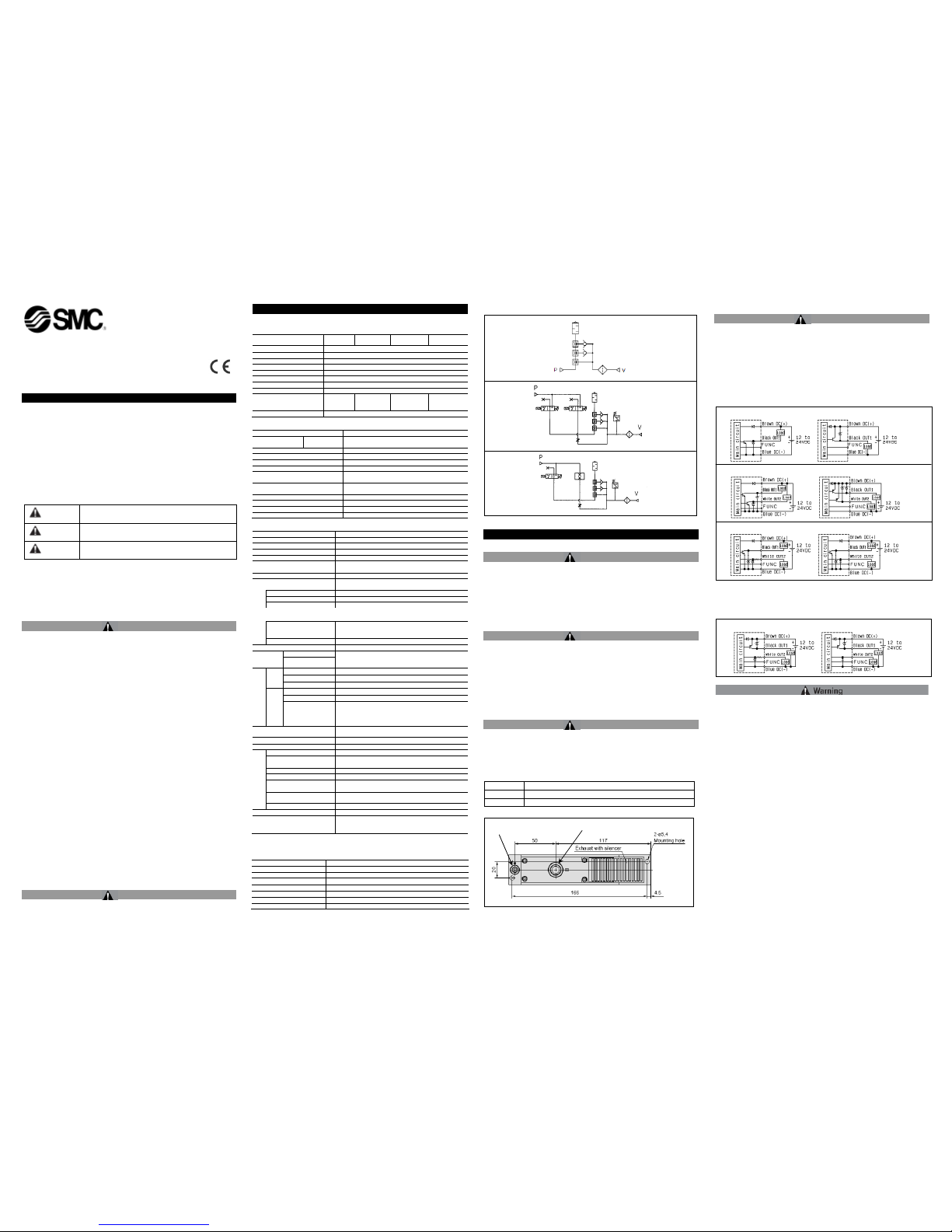
2.2 Circuit Symbols
3 Installation
3.1 Installation
Warning
• Do not install the product unless the safety instructions have been read
and understood
3.2 Environment
Warning
• Do not use in an environment where corrosive gases, chemicals, salt
water or steam are present.
• Do not use in an explosive atmosphere.
• Do not expose to direct sunlight. Use a suitable protective cover.
• Do not install in a location subject to vibration or impact. Check the
product specifications.
• Do not mount in a location exposed to radiant heat.
3.3 Piping
Warning
• Before piping make sure to clean up chips, cutting oil, dust etc.
• When installing piping or fittings, ensure sealant material does not enter
inside the port. When using seal tape, leave 1.5 to 2 threads exposed on
the end of the pipe/fitting.
• Tighten fittings to the specified tightening torque.
Thread Tightening Torque
M5 By hand + 1/6 turn with a wrench (1/4 turn for miniature fittings)
Rc 1/8 7 to 9
3.4 Electrical Connection
Caution
• When DC power is connected to a solenoid valve equipped with light
and/or surge voltage suppressor, check for polarity indications.
• For polarity indications:
• No diode to protect polarity: if polarity connection is wrong, the
diode in the valve or switching device at control equipment or
power supply may be damaged.
• With diode to protect polarity: if polarity connection is wrong, the
valve does not switch.
Vacuum Pressure Switch Wiring Diagram (ZSE30A type)
Wiring electronic Pressure Switch
• Confirm wire colours and terminal numbers when wiring.
Since incorrect wiring can lead to breakage or failure of the switch as
well as malfunction, perform wiring after confirming wiring colours and
terminal numbers with the instruction manual.
• Avoid repeatedly bending or stretching lead wires.
Broken lead wires will result from applying bending stress or stretching
force to the lead wires. In the event that lead wires are damaged
creating a possibility of malfunction, replace the entire product. (For
cases in which the lead wires cannot be replaced through grommets.)
• Confirm proper insulation of wiring.
Be certain that there is no faulty wiring insulation (contact with other
circuits, ground fault, improper insulation between terminals, etc.).
Damage may occur due to excess current flow into a switch.
• Do not wire with power lines or high voltage lines.
Wire separately from power lines or high voltage lines, avoiding parallel
wiring or wiring in the same conduit. Control circuits containing switches
may malfunction due to noise from other lines.
• Do not allow short circuiting of loads.
Use caution, as switches will be damaged if a load is short circuited. Be
especially careful not to reverse the power supply line (Brown) and the
output line (Black).
Pressure supply port
Vacuum port
Without valve
With valve
K1 type
K2 type
With valve
Output specification: N
Output specification: P
Output specific
ation: A Output specification: B
Output specification: C
Output specification: D
Output specification: E
Output specification: F
Page 2
ZL112-TFK33GB
3.5 Mounting
• Read the instruction manual carefully.
The product should be m ounted and operated with a good
understanding of its contents. Also, keep the manual where it can be
easily referred to at any time.
• Ensure space for maintenance.
Ensure the necessary space for maintenance activities.
• Be sure to tighten screws with the proper torque.
When mounting, tighten screws with the recommended torque.
• Do not obstruct the exhaust port of the ejector.
If the exhaust port is obstructed when mounted, a vacuum will not be
generated.
Electronic Pressure Switch
• Do not use if equipment does not operate properly.
Verify correct mounting by suitable function and leakage inspections
after air and power are connected following mounting or maintenance.
• Do not drop or bump.
Do not drop, bump or apply excessive impact (1000m/s²) when handling.
Even if the switch body is not damaged, the switch may suffer internal
damage that will lead to malfunction.
• Hold the product from the body side when handling.
The tensile strength of the power cord is 49N, and pulling it with a force
greater than this can cause failure. Hold by the body when handling.
• Turn the setting trimmer gently using a watchmakers screwdriver.
Turn the setting trimmer gently using a watchmakers screwdriver. Do not
turn beyond the stoppers located at both ends. If the trimmer is broken,
adjustment will be impossible.
• Pressure port
Do not insert wire, etc., from the pressure port. This will damage the
pressure sensor, making it impossible to obtain normal operation.
3.6 Air Supply Circuit
• When designing t he air supply circuit ensure that pipe sizes have
sufficient capacity to prevent any pressure drop within the generator, this
also applies to valves and fittings.
• The supply air should be clean and oil free.
• Vacuum circuit
Ensure that the piping from generator t o vacuum pad is kept as short as
possible to prevent restriction and leakage.
• Vacuum pads
When installing vacuum generators the rule is one generator → one
vacuum pad. If this rule is ignored t hen possible loss of vacuum during
pick-up will occur.
4 Maintenance
4.1 General Maintenance
• Not following proper maintenance procedures could cause the product to
malfunction and lead to equipment damage.
• If handled improperly, compressed air can be dangerous. Maintenance
of pneumatic systems should be performed only by qualified personnel.
• Before performing maintenance, turn off the power supply and be sure to
cut off the supply pressure. Confirm that the air is released to
atmosphere.
• After installation and maintenance, apply operating pressure and power
to the equipment and perform appropriate functional and leakage tests to
make sure the equipment is installed correctly.
• Do not make any modification to the product.
• Do not disassemble the product, unless required by installation or
maintenance instructions.
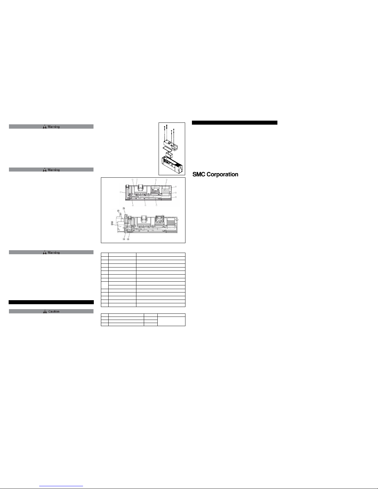
Replacement procedure of Part No.: ZL112-G
Disassembly
• Remove hexagon socket head cap screw
(M3×30: 4 pieces).
• Detach suction cover from body.
• Remove suction filter.
Assembly
• Assemble component parts in reverse order of
disassembly.
• When assembling, be sure that the gasket is
fitted into the appropriate groove respectively.
• (Note: Take care not to drop vacuum pressure
gauge.)
Parts List
No. Description
Note
1 Suction Cover
2 Front Cover
Without Valve
3 End Cover
4 Body
5 Vacuum Sensor Unit
6 Nozzle
7 Diffuser
Detent Plug
Other than vacuum switch
8
Lead Wire C
over Vacuum switch specification
12 Front Cover B
With Valve
13 Valve Plate
With Valve
14 Needle With Valve
15 Supply Valve (N.C.)
With Valve
16 Release Valve (N.C)
With Valve
Replacement Parts
No.
Description Material Part No.
9 Sound absorbing material B PVF
10 Sound absorbing material A PVF
11 Suction Filter PE
ZL112-SP01
(Set No. for 9,10 &
11)
When ordering a vacuum pressure gauge or digital vacuum pressure
switch separately, use the part numbers shown in the option specifications
on page 3.
Contacts
AUSTRIA
(43) 2262 62280-0
LATVIA
(371) 781 77 00
BELGIUM
(32) 3 355 1464
LITHUANIA
(370) 5 264 8126
BULGARIA
(359) 2 974 4492
NETHERLANDS
(31) 20 531 8888
CZECH REP.
(420) 541 424 611
NORWAY
(47) 67 12 90 20
DENMARK
(45) 7025 2900
POLAND
(48) 22 211 9600
ESTONIA
(372) 651 0370
PORTUGAL
(351) 21 471 1880
FINLAND
(358) 207 513513
ROMANIA
(40) 21 320 5111
FRANCE
(33) 1 6476 1000
SLOVAKIA
(421) 2 444 56725
GERMANY
(49) 6103 4020
SLOVENIA
(386) 73 885 412
GREECE
(30) 210 271 7265
SPAIN
(34) 945 184 100
HUNGARY
(36) 23 511 390
SWEDEN
(46) 8 603 1200
IRELAND
(353) 1 403 9000
SWITZERLAND
(41) 52 396 3131
ITALY
(39) 02 92711
UNITED KINGDOM
(44) 1908 563888
URL : http// www.smcworld.com (Global) http// www.smceu.com (Europe )
Specifications are subject to change without prior notice from the manufactu rer.
© 2013 SMC Corporation All Rights Reserved.
With Valve
Without Valve
 Loading...