

SMC Networks XT323-4, XT323-4Y, XT323-4YF Installation And Maintenance Manual
XT323-4-TFK57GB
Installation and Maintenance Manual
3 Port Solenoid Valve
XT323-4, XT323-4Y, XT323-4YF
1 Safety Instructions
• This manual contains essential information for the protection of users
and others from possible injury and/or equipment damage.
• Read this manual before using the product, to ensure correct handling,
and read the manuals of related apparatus before use.
• Keep this manual in a safe place for future reference.
• These instructions indicate the level of potential hazard by label of
“Caution”, “Warning” or “Danger”, followed by important safety
information which must be carefully followed.
• To ensure safety of personnel and equipment the safety instructions in
this manual and the product catalogue must be observed, along with
other relevant safety practices.
Warning
• The compatibility of pneumatic equipment is the responsibility of the
person who designs the pneumatic system or decides its specifications.
Since the products specified here can be used in various operating
conditions, their compatibility with the specific pneumatic system must
be based on specifications or after analysis and/or tests to meet
specific requirements.
• Only trained personnel should operate pneumatically operated
machinery and equipment.
Compressed air can be dangerous if an operator is unfamiliar with it.
Assembly, handling or repair of pneumatic systems should be
performed by trained and experienced personnel.
• Do not service machinery/equipment or attempt to remove
components until safety is confirmed.
1) Inspection and maintenance of machinery/equipment should only be
performed after confirmation of safe locked-out control positions.
2) When equipment is to be removed, confirm the safety process as
mentioned above. Switch off air and electrical supplies and exhaust all
residual compressed air in the system.
3) Before machinery/equipment is re-started, ensure all safety
measures to prevent sudden movement of cylinders etc. (Supply air
into the system gradually to create back pressure, i.e. incorporate a
soft-start valve).
• Do not use this product outside of the specifications. Contact
SMC if it is to be used in any of the following conditions:
1) Conditions and environments beyond the given specifications, or if
the product is to be used outdoors.
2) Installations in conjunction with atomic energy, railway, air
navigation, vehicles, medical equipment, food and beverage, recreation
equipment, emergency stop circuits, press applications, or safety
equipment.
3) An application which has the possibility of having negative effects on
people, property, or animals, requiring special safety analysis.
Caution
• Ensure that the air supply system is filtered to 5 microns.
2 Specifications
2.1 General Specifications
2.2 Symbol
OUT
IN EXH
2.3 Piping
3 Installation
3.1 Installation
Warning
• Do not install the product unless the safety instructions have been read
and understood.
3.2 Environment
Warning
• Do not use in an environment where the product is directly exposed to
corrosive gases, chemicals, salt water or steam.
• Do not use in an explosive atmosphere.
• The product should not be exposed to prolonged sunlight.
Use a protective cover.
• Do not mount the product in a location where it is subject to strong
vibrations and/or shock. Check the product specifications.
• Do not mount the product in a location exposed to radiant heat.
3.3 Piping
Caution
• Before piping make sure to clean up chips, cutting oil, dust etc.
• When installing piping or fittings, ensure sealant material does not enter
inside the port. When using seal tape, leave 1.5 to 2 threads exposed on
the end of the pipe/fitting.
• Tighten fittings according to appropriate tightening torque.
XT323-4
IN
IN
EXH
EXH
OUT
Electrical
connection
Electrical
connection
OUT
XT323-4Y(F)
3 Installation (continued)
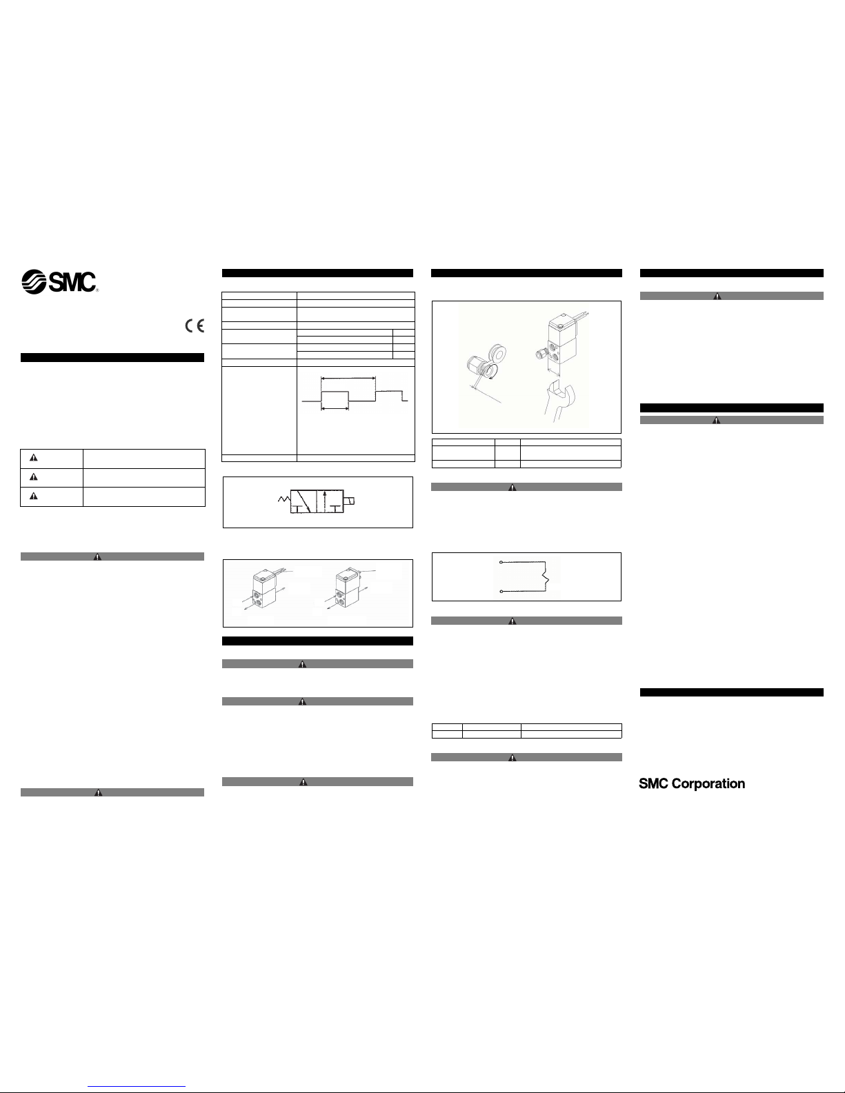
• The arrow on the base of the valve denotes the flow direction.
• Connect piping and fittings by holding the valve body with a spanner.
3.4 Electrical connection
Caution
• The coil of the XT323-4 has been designed for a fast response time so
cannot be continuously energized.
Thread Appropriate tightening torque (Nm)
XT323-4
XT323-4Y
Rc1/8 7 to 9
XT323-4YF G1/8 See specification of fitting used
Seal
Tape
1.5 or 2 threads
Direction
of winding
Fitting
3.5 Mounting
Caution
• If air leakage increases or equipment does not operate properly,
stop operation.
After mounting or maintenance, connect the compressed air and power
supply, check for leakage and operate the valve to confirm that the unit is
mounted properly.
• Instruction manual
Mount and operate the product after reading the manual carefully and
understanding its contents. Keep the manual where it can be referred to
as necessary.
• Painting and coating
Warnings and specifications printed on the product should not be erased,
removed or covered.
• For mounting use the two threads in the base of the valve.
3.6 Lubrication
Caution
• SMC products have been lubricated for life at manufacture, and do not
require lubrication in service.
• If a lubricant is used in the system, use turbine oil Class 1(no additive), ISO
VG32. Once lubricant is used in the system, lubrication must be continued
because the original lubricant applied during manufacturing will be washed
away.
Thread Appropriate tightening torque (Nm)
SOL
6 Contacts
URL http://www.smcworld.com (Global) http://www.smceu.com (Europe)
Specifications are subject to change without prior notice from the manufacturer.
© 2009 SMC Corporation All Rights Reserved.
4 Maintenance
4.1 General Maintenance
Caution
• Not following proper maintenance procedures could cause the product
to malfunction and lead to equipment damage.
• If handled improperly, compressed air can be dangerous. Maintenance
of pneumatic systems should be performed only by qualified personnel.
• Before performing maintenance, ensure the supply pressure is shut off
and all residual air pressure is released from the system.
• After maintenance apply operating pressure and power to the
equipment and check for proper operation and possible air leaks. If
operation is abnormal, verify product set-up parameters.
• Do not make any modification to the product.
• Do not disassemble the product, unless required by installation or
maintenance instructions.
Please inquire to SMC.
5 Limitations of Use
Warning
• Do not exceed any of the specifications laid out in section 2 of this
document or the specified product catalogue.
Caution
If instructions are not followed there is a
possibility of injury or equipment damage.
Warning
If instructions are not followed there is a
possibility of serious injury or loss of life.
Danger
In extreme conditions, there is a possibility of
serious injury or loss of life.
AUSTRIA (43) 2262 62280 NETHERLANDS (31) 20 531 8888
BELGIUM (32) 3 355 1464 NORWAY (47) 67 12 90 20
CZECH REP. (420) 541 424 611 POLAND (48) 22 211 9600
DENMARK (45) 7025 2900 PORTUGAL (351) 21 471 1880
FINLAND (358) 207 513513 SLOVAKIA (421) 2 444 56725
FRANCE (33) 1 6476 1000 SLOVENIA (386) 73 885 412
GERMANY (49) 6103 4020 SPAIN (34) 945 184 100
GREECE (30) 210 271 7265 SWEDEN (46) 8 603 1200
HUNGARY (36) 23 511 390 SWITZERLAND (41) 52 396 3131
IRELAND (353) 1 403 9000 UNITED KINGDOM (44) 1908 563 888
ITALY (39) 02 92711
Operating Fluid Air
Operating Pressure Range 0 ~0.7 MPa
Ambient and Operating
Air Temperature
5~60°C
Effective Sectional Area 10mm²
Port Size
XT323-4, XT323-4Y Rc1/8
XT323-4YF G1/8
Mass
XT323-4 116g
XT323-4Y, XT323-4YF 137g
Resistance
44Ω
Operating Voltage
Duty Ratio = Less than 50%
T1: Time per cycle, T2 Energizing time
Duty ratio is the percentage of energizing
time per cycle.
Duty Ratio = T2/T1x100%
24 V
T2
T1
Frequency 300~1500 c.p.m.
 Loading...