

SMC Networks WiShare SMCWTVA100 User Manual

USER GUIDE
WiShare
Wireless TV Adapter
SMCWTVA100

Wireless TV Adapter
User Guide
No. 1, Creation Road III,
Hsinchu Science Park,
30077, Taiwan, R.O.C.
TEL: +886 3 5638888
Fax: +886 3 6686111
July 2013
E072013-KS-R02

Information furnished by SMC Networks, Inc. (SMC) is believed to be accurate and reliable.
However, no responsibility is assumed by SMC for its use, nor for any infringements of patents or
other rights of third parties which may result from its use. No license is granted by implication or
otherwise under any patent or patent rights of SMC. SMC reserves the right to change specifications
at any time without notice.
Copyright © 2013 by
SMC Networks, Inc.
No. 1 Creation Road III,
Hsinchu Science Park,
30077, Taiwan, R.O.C.
All rights reserved
Trade m ar k s :
SMC is a registered trademark; and Barricade, EZ Switch, TigerStack, TigerSwitch, and TigerAccess
are trademarks of SMC Networks, Inc. Other product and company names are trademarks or
registered trademarks of their respective holders.

WARRANTY AND PRODUCT REGISTRATION
To register SMC products and to review the detailed warranty statement,
please refer to the Support Section of the SMC Website at http://
www.smc.com.
– 4 –

COMPLIANCES
Declaration of Conformity (DoC) can be obtained from
www.smc.com
-> support -> download -> declarations & certifications
FEDERAL COMMUNICATION COMMISSION INTERFERENCE STATEMENT
This equipment has been tested and found to comply with the limits for a
Class B digital device, pursuant to part 15 of the FCC Rules. These limits
are designed to provide reasonable protection against harmful interference
in a residential installation. This equipment generates, uses and can
radiate radio frequency energy and, if not installed and used in accordance
with the instructions, may cause harmful interference to radio
communications. However, there is no guarantee that interference will not
occur in a particular installation. If this equipment does cause harmful
interference to radio or television reception, which can be determined by
turning the equipment off and on, the user is encouraged to try to correct
the interference by one or more of the following measures:
◆ Reorient or relocate the receiving antenna
◆ Increase the separation between the equipment and receiver
◆ Connect the equipment into an outlet on a circuit different from that to
which the receiver is connected
◆ Consult the dealer or an experienced radio/TV technician for help
This device complies with Part 15 of the FCC Rules. Operation is subject to
the following two conditions: (1) This device may not cause harmful
interference, and (2) this device must accept any interference received,
including interference that may cause undesired operation.
FCC Caution: Any changes or modifications not expressly approved by the
party responsible for compliance could void the user's authority to operate
this equipment.
N
OTE
:
The manufacturer is not responsible for any radio or TV interference
caused by unauthorized modifications to this equipment. Such
modifications could void the user’s authority to operate the equipment.
CE MARK DECLARATION OF CONFORMANCE FOR EMI AND SAFETY (EEC)
– 5 –

This information technology equipment complies with the requirements of
the Council Directive 89/336/EEC on the Approximation of the laws of the
Member States relating to Electromagnetic Compatibility and 73/23/EEC
for electrical equipment used within certain voltage limits and the
Amendment Directive 93/68/EEC. For the evaluation of the compliance
with these Directives, the following standards were applied:
◆ Health (Article 3.1(a) of the R&TTE Directive)
■
RF exposure related standards use ERC REC 519/EC
◆ Safety (Article 3.1(a) of the R&TTE Directive)
■
LVD: EN60950-1:2006+A11:2009+A1:2010
◆ Electromagnetic compatibility (Article 3.1 (b) of the R&TTE Directive)
■
EN 301 489-1 V.1.8.1
■
EN 301-489-17 V2.1.1
◆ Radio frequency spectrum usage (Article 3.2 of the R&TTE Directive)
■
EN 300 328 V1.7.1
■
EN 301 893 V1.6.1
– 6 –
ABOUT THIS GUIDE
PURPOSE This guide details the hardware features of the wireless TV adapter,
including its physical and performance-related characteristics, and how to
install the device and use its configuration software.
AUDIENCE This guide is for Smart Phone and PC users with a working knowledge of
computers. You should be familiar with Windows and Android operating
system concepts.
CONVENTIONS The following conventions are used throughout this guide to show
information:
N
OTE
:
Emphasizes important information or calls your attention to related
features or instructions.
C
AUTION
damage the system or equipment.
W
ARNING
:
Alerts you to a potential hazard that could cause loss of data, or
:
Alerts you to a potential hazard that could cause personal injury.
RELATED PUBLICATIONS The following publication gives basic information on how to install and use
the wireless TV adapter.
Quick Installation Guide
Also, as part of the wireless TV adapter’s software, there is online help that
describes all configuration related features.
REVISION HISTORY This section summarizes the changes in each revision of this guide.
JULY 2013 REVISION
Adds new features released for the second firmware version.
OCTOBER 2012 REVISION
This is the first revision of this guide.
– 7 –

CONTENTS
WARRANTY AND PRODUCT REGISTRATION 4
C
OMPLIANCES 5
BOUT THIS GUIDE 7
A
C
ONTENTS 8
F
IGURES 11
ABLES 14
T
1I
NTRODUCTION 15
Overview of the Wireless TV Adapter 15
Main Features 15
Package Contents 16
Key Hardware Features 16
2SYSTEM REQUIREMENTS AND CONNECTIONS 18
System Requirements for PC to TV Mode 18
System Requirements for Mirror PBC and PIN Mode (Miracast) 18
System Requirements for Media Share Mode (DLNA) 19
3INSTALLATION GUIDE 20
How to Connect the TV Adapter 20
Install Screencasting Software 21
Connect a Device to the SMCWTVA100 21
Non-Bridged Connection Setups 26
Wired Connection Setup 26
Wireless Connection Setup 27
Hardware Reset to Factory Default Settings 27
4SOFTWARE INSTALLATION 29
PC to TV and AirFun Installation (Windows) 29
iMediaShare App Installation (Android) 39
iMediaShare App Installation (iOS) 42
– 8 –

C
ONTENTS
5OPERATION MODES 45
PC to TV Mode 45
Using PC to TV (Windows PC Users) 45
Additional PC to TV Controller Menu Items 47
Mirror PIN and PBC Mode 48
Mirror PBC Versus PIN Mode 48
Setup Mirror PBC or PIN From an Android Device 49
Media Share Mode (DLNA Mode) 53
Using AirFun
(Windows PC Users) 53
Using iMediaShare (Android Users) 58
Using iMediaShare (iOS Users) 60
NAS (USB) Mode 63
Using NAS Mode 63
Additional Controls In NAS (USB) Mode 64
Firmware Upgrade 64
Remote Options 65
Setup Using the OSD Menu 67
Network 68
Audio 69
Video 69
System 70
6WEB CONFIGURATION 71
Network Topology and Settings 71
Quick Setting 71
Network Settings 71
Wireless Configuration 72
Basic Settings 72
Security Settings 73
Band Settings 73
Virtual AP Bridge 74
Display Output Setting 75
Display Setting 75
Web UI Password 75
Password Setting 75
Mode Setting 76
– 9 –

C
ONTENTS
Mode Switch 76
Additional Functions 77
Status 77
Configuration 77
Remote 78
Restart 78
Reset to Factory Default Configuration 78
7SPECIFICATIONS 79
– 10 –

FIGURES
Figure 1: Rear View 16
Figure 2: Side View 17
Figure 3: Connecting to the SMCWTVA100 using a PC 22
Figure 4: Enter the URL of the SMCWTVA100 22
Figure 5: Web UI Login 23
Figure 6: Quick Setting 23
Figure 7: Stand-Alone Connection Setup 24
Figure 8: Bridge to Wireless Connection Setup 25
Figure 9: Bridge to Ethernet (Wired) Connection Setup 26
Figure 10: “Wired” Connection Setup 27
Figure 11: Wireless Connection Setup 27
Figure 12: Setup Wizard Start 29
Figure 13: Google Play Store 39
Figure 14: Search DLNA Software App - Android Users 39
Figure 15: Install iMediaShare App - Android Users 40
Figure 16: Download iMediaShare App - Android Users 40
Figure 17: iMediaShare App is Installed - Android Users 41
Figure 18: Launch iMediaShare App - Android Users 41
Figure 19: App Store 42
Figure 20: Search DLNA Software App - iOS Users 42
Figure 21: Install iMediaShare App - iOS Users 43
Figure 22: iMediaShare App Install Complete - iOS Users 43
Figure 23: Activate iMediaShare App - iOS Users 44
Figure 24: PC to TV Mode Screen 46
Figure 25: PC to TV Icon 46
Figure 26: PC to TV Server Selection and Login Window 46
Figure 27: PC to TV Controller 47
Figure 28: Mirror Mode—SMCWTVA100 in Mirror PBC and PIN Mode. 49
Figure 29: Mirror Mode—Accessing Miracast Within Android 49
Figure 30: Mirror Mode—Launching Miracast. 50
Figure 31: Mirror Mode—Selecting the SMCWTVA100 50
– 11 –

C
ONTENTS
Figure 32: Mirror Mode—Connecting 51
Figure 33: Mirror Mode—Connected 52
Figure 34: Media Share Mode 53
Figure 35: Connect to SMCWTVA100 53
Figure 36: Launch AirFun 54
Figure 37: Search and Connect to Device 54
Figure 38: AirFun Activate 54
Figure 39: Select Photos 55
Figure 40: View Photo 55
Figure 41: Select Audio File 56
Figure 42: Play Audio File 56
Figure 43: Select Video File 57
Figure 44: Play Video 57
Figure 45: Connect to SMCWTVA100 58
Figure 46: Launch iMediaShare 58
Figure 47: Select the Desired File Type 59
Figure 48: Select a Photo 59
Figure 49: Photo Ready for Display 60
Figure 50: Connect to SMCWTVA100 60
Figure 51: Launch iMediaShare 61
Figure 52: Select the Desired File Type 61
Figure 53: Select a Photo 62
Figure 54: Photo Ready for Display 62
Figure 55: USB Mode 63
Figure 56: Remote Functions for NAS (USB) Mode 64
Figure 57: Upgrade Firmware 65
Figure 58: Upgrade Firmware Completed 65
Figure 59: Remote Control 66
Figure 60: Download AirFun Page 67
Figure 61: Wireless LAN Setup 67
Figure 62: Setup Main Page 68
Figure 63: Network Settings 72
Figure 64: Wireless Settings - Basic Setting 73
Figure 65: Wireless Settings-Security Settings 73
Figure 66: Wireless Settings-Band Settings 74
Figure 67: Virtual AP Bridge 74
– 12 –

C
ONTENTS
Figure 68: Display Settings 75
Figure 69: Password Setting 76
Figure 70: Mode Switch 76
Figure 71: Status Menu 77
Figure 72: Configuration Menu Item 77
Figure 73: Remote Menu Item 78
Figure 74: Restart Confirmation Dialog Box 78
– 13 –

TABLES
Table 1: System Requirements (PC to TV Mode) 18
Table 2: Current Miracast Devices Supported 18
Table 3: System Requirements (Media Share Mode) 19
Table 4: Remote Option Button Menus 66
– 14 –

1 INTRODUCTION
This chapter includes these sections:
◆ Overview of the Wireless TV Adapter
◆ Package Contents
◆ Key Hardware Features
OVERVIEW OF THE WIRELESS TV ADAPTER
Enjoy all of your personal and online content on a big screen with a simple
wireless connection. The SMCWTVA100 can use PC to TV, Media Share
(DLNA or Digital Living Network Alliance), Miracast and USB drive transfer
technology to share your mobile device or laptop content through a Wi-Fi
link to your TV or room projector. You can sit back on a couch and enjoy
your favorite movies, videos, photos, online shows and more, all in full HD.
You can also make business presentations or play music, photos or video
directly from your smartphone or tablet by Wi-Fi. The SMCWTVA100 can be
used with Windows, Android, and Apple iOS systems to share your
happiness.
MAIN FEATURES ◆ PC to TV—All PC video and audio output is “screencast” and displayed
on your TV.
◆ Miracast—Android smartphone screen and sound is “screencast” and
displayed on your TV.
◆ MediaShare—DLNA technology displays selected video, image, and
sound files from PCs, tablets, and smartphones onto your TV.
◆ USB interface—USB thumb or disk drive media files are displayed on
your TV.
◆ Dual-band Wi-Fi connectivity (2.4G or 5G Band 2T2R 300 Mbps)
◆ HDMI/CVBS support—To support both new and previous generation
televisions, monitors, and projectors.
◆ Micro-USB DC in port—Any convenient USB power source can be
used.
◆ Web UI—Web UI (User Interface) with firmware upgrade capability.
– 15 –
PACKAGE CONTENTS
12 345
C
HAPTER
The packaging should contain the following items:
◆ SMCWTVA100
◆ HDMI cable
◆ AV Cable
◆ Power adapter
◆ Quick Installation Guide
◆ Resource CD, including this User Guide and AirFun Software
N
OTE
:
Make sure that the package contains the above items. If any of the
listed items are damaged or missing, please contact your distributor.
1
| Introduction
Package Contents
KEY HARDWARE FEATURES
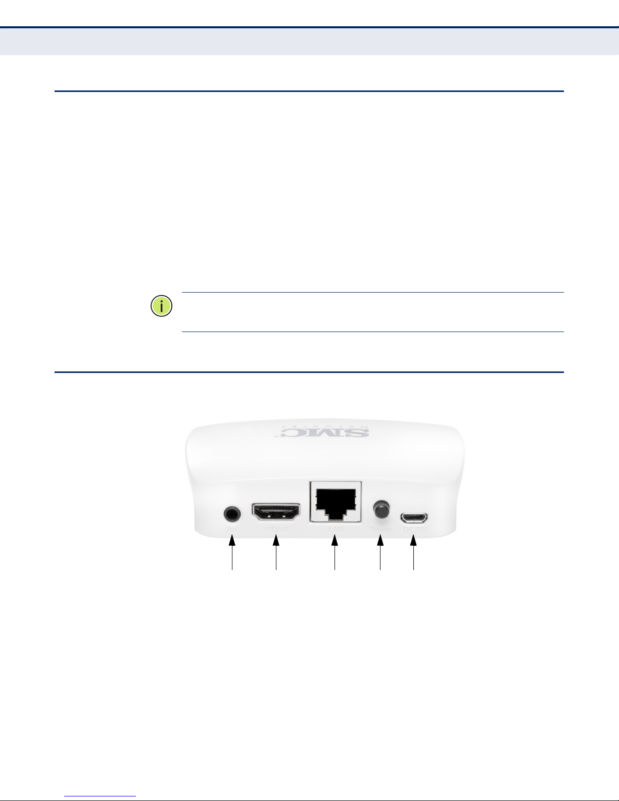
Figure 1: Rear View
The following items are located on the rear panel (from left to right).
1. AV
This CVBS port connects the TV adapter output signal to a TV or projector.
2. HDMI
This port connects the TV adapter output signal to a TV or projector.
– 16 –
C
67
HAPTER
1
| Introduction
Key Hardware Features
3. ETHERNET LAN PORT
This port connects the TV adapter to a LAN over Ethernet. For example,
you can connect it to a spare port on your home WI-FI router.
4. POWER BUTTON
When the DC power adapter is attached and connected to a power source,
the power button must be depressed to power on the unit.
5. DC 5V
The micro-USB power socket is where you connect the power adapter. Use
the power adapter provided with the TV adapter or any suitable device
which can supply DC voltage over a USB connection.
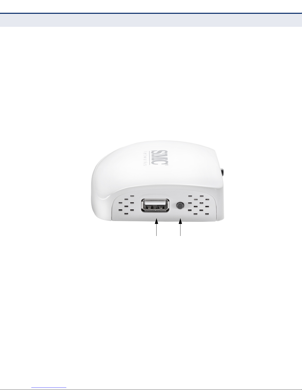
Figure 2: Side View
The following items are located on the side panel (from left to right).
6. USB PORT
This port is for upgrading firmware only. Connect an external USB storage
device, such as a thumb drive, to this port.
7. MODE BUTTON
Press the button to switch between PC to TV, Miracast PBC/PIN,
MediaShare, and USB modes.
– 17 –

2 SYSTEM REQUIREMENTS AND
CONNECTIONS
This chapter includes these sections:
◆ System Requirements for PC to TV Mode
◆ System Requirements for Mirror PBC and PIN Mode (Miracast)
◆ System Requirements for Media Share Mode (DLNA)
SYSTEM REQUIREMENTS FOR PC TO TV MODE
PC to TV software uses a proprietary protocol similar to Wi-Di however,
instead of being limited to the few models that support Wi-Di, you can use
it on any Windows 7 or Windows 8 OS computer.
Table 1: System Requirements (PC to TV Mode)
System Component Requirement
PC or Laptop CPU: 1.6 GHz or better
Memory: 1.0 GB or better
Network: 802.11g/n Wi-Fi and/or 100/1000 Mbps Ethernet
SYSTEM REQUIREMENTS FOR MIRROR PBC AND PIN MODE (MIRACAST)
Mirror PBC and PIN mode is supported by a limited number of Android 4.2
release devices. Please check the SMC website for a list of currently
supported devices or check with your device’s manufacturer. Currently the
following devices are known to function correctly with the SMCWTVA100
using Mirror mode:
Table 2: Current Miracast Devices Supported
Manufacturer Model
Samsung S2, S4, Note2, Note8
LG Optimus G, LG-E975
Sony Xperia Z, Xperia TX
Google Nexus 4
Sharp SH-10D
HTC New HTC one
Xiaomi 2S
– 18 –

C
HAPTER
System Requirements for Media Share Mode (DLNA)
N
OTE
:
Android 4.2 or higher smartphones and tablets with Miracast support
2
| System Requirements and Connections
for Wi-Fi Direct Transfer.
SYSTEM REQUIREMENTS FOR MEDIA SHARE MODE (DLNA)
The SMCWTVA100 is designed to be a DLNA-DMR (digital media renderer)
device, which means you are able to stream video, music, and photo
content from a PC (Windows 7 or Windows 8 OS), smartphone, or tabletPC to your TV.
Table 3: System Requirements (Media Share Mode)
System Component Requirement
PC or Laptop CPU: 1.6 GHz or better
Smartphone CPU: 800 MHz or better
Tablet CPU: 600 MHz or better
Memory: 1.0 GB or better
Network: 802.11g/n Wi-Fi and/or 100/1000 Mbps Ethernet
Memory: 256 MB or better
Network: 802.11g/n Wi-Fi or better
Memory: 256 MB or better
Network: 802.11g/n Wi-Fi or better
– 19 –

3 INSTALLATION GUIDE
The sections that follow describe the hardware and software installation
procedures and some additional configuration required to connect your
SMCWTVA100 into your existing LAN or WLAN. The following sections are
included:
◆ How to Connect the TV Adapter
◆ Install Screencasting Software
◆ Connect a Device to the SMCWTVA100
◆ Non-Bridged Connection Setups
HOW TO CONNECT THE TV ADAPTER
For a basic “stand-alone” hardware install of the TV adapter, perform the
following steps:
N
OTE
:
If Internet is required for your display function, before installing the
TV adapter, make sure your PC, smartphone or tablet-PC is successfully
connected to the Internet through a broadband service. If there are any
problems, first contact your ISP to resolve them.
1. Plug in the power cord.
2. Connect the HDMI cable to the HDMI output of the SMCWTVA100 and
to the HDMI input of your TV, projector or monitor.
3. To turn on the SMCWTVA100, push in the power button until it clicks in
the depressed position.
4. Follow the on-screen instructions to set up the SMCWTVA100. The
system default mode is PC to TV mode, which means it is ready to
display any media from your PC including presentations, video, music,
and photos.
5. You can switch between five modes by pushing the mode button on the
side of the unit (next to the USB port) two or three times. The onscreen instructions will prompt you to push the button again after the
first or second push.
– 20 –

INSTALL SCREENCASTING SOFTWARE
Whether you want to use a PC, tablet or smartphone with the
SMCWTVA100, your devices will need screencasting software to be able to
display and play your device contents.
1. Download and install the required software on your PC, smartphone, or
tablet.
■
For Windows 7 and 8 users, install the PC to TV and AirFun
application from the Resource CD. Follow the on-screen
instructions. See “PC to TV and AirFun Installation (Windows)” on
page 29.
■
For Android users, install a DLNA software app, which can be
downloaded from Google Play (formerly Android Market).
Supported DLNA App: iMediashare. See “iMediaShare App
Installation (Android)” on page 39.
C
HAPTER
Install Screencasting Software
3
| Installation Guide
■
For Apple iOS users, install a DLNA software app, which can be
downloaded from the Apple App Store. Supported DLNA App:
iMediashare. See “iMediaShare App Installation (iOS)” on page 42.
CONNECT A DEVICE TO THE SMCWTVA100
The SMCWTVA100 operates as a wireless access point (AP) without
Internet access. If you need bridged access to the Internet through the
SMCWTVA100 to a local LAN with internet connectivity, such as your
wireless router, you must configure the network settings.
The default setting for the SMCWTVA100 is “Virtual AP only” (stand-alone)
mode. To use this device either in stand-alone mode or with an Internet
connection, perform the procedure as follows:
1. Connect the SMCWTVA100. See “How to Connect the TV Adapter” on
page 20.
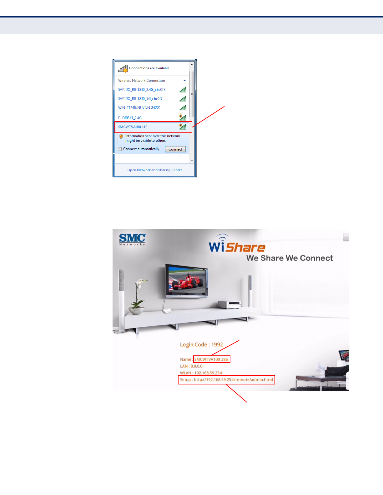
2. Connect your laptop, smartphone, or tablet-PC to the SMCWTVA100
using Wi-Fi. The SMCWTVA100 AP default SSID is the shown on the
initial screen as SMCWTVA100 xxx. See Figure 4 on page 22; the
“Name:” field.
– 21 –
C
Select and then connect to the
SMCWTVA100 access point.
INPUT THIS URL INTO YOUR
BROWSER’S ADDRESS FIELD.
CONNECT TO THIS DEFAULT SSID
USING WI-FI.
HAPTER
Connect a Device to the SMCWTVA100
Figure 3: Connecting to the SMCWTVA100 using a PC
3
| Installation Guide
3. Enter the URL of the SMCWTVA100 Web UI (http://192.168.59.254/
remote/admin.html) into the address bar of your web browser. See
Figure 4 below; the “Setup:” field.
Figure 4: Enter the URL of the SMCWTVA100
4. When the SMCWTVA100 Web UI finishes loading, as shown in Figure 5,
login with the password:
– 22 –
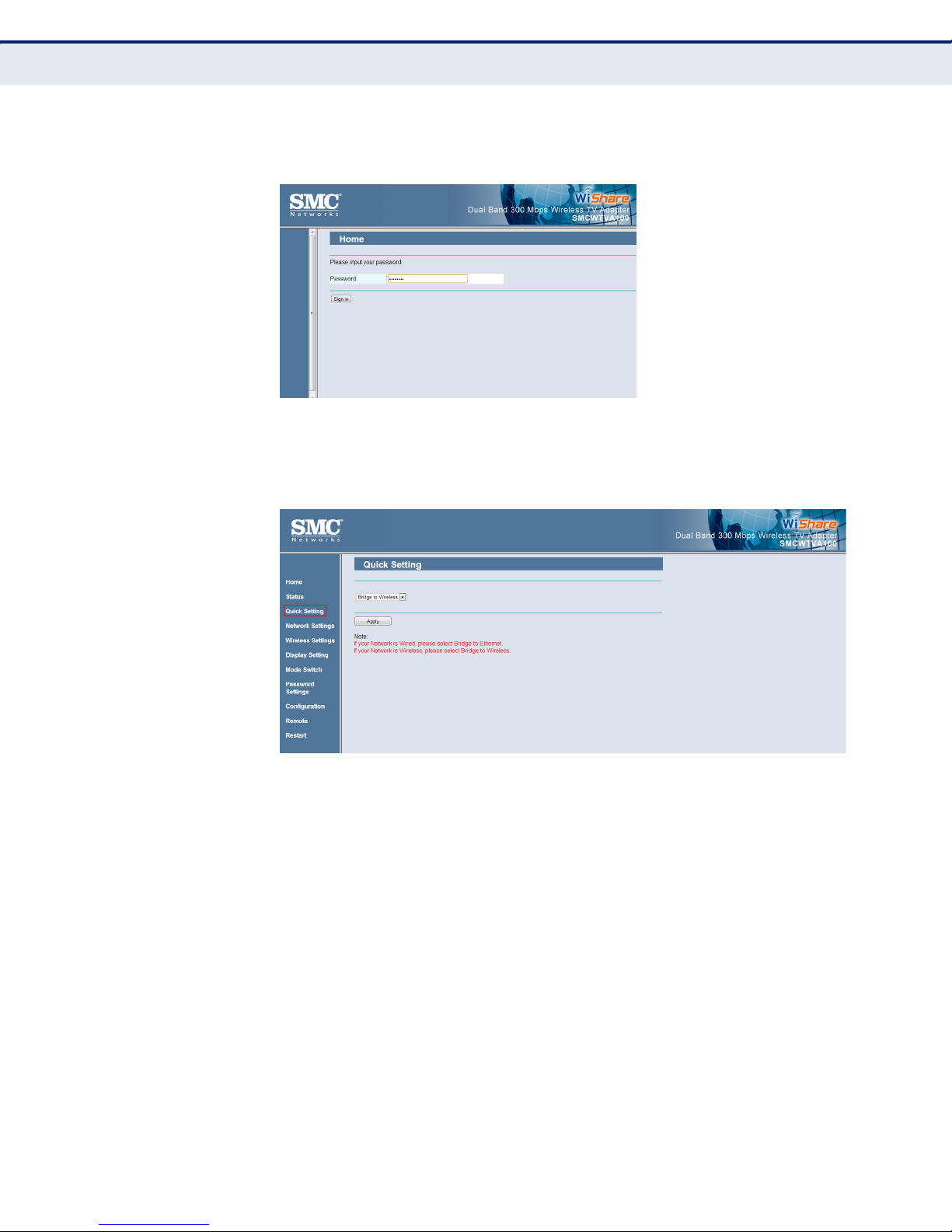
C
■
smcadmin
Figure 5: Web UI Login
HAPTER
Connect a Device to the SMCWTVA100
3
| Installation Guide
5. In the menu selection on the left, click on the “Quick Setting” menu
item. The Quick Setting menu appears as shown in Figure 6.
Figure 6: Quick Setting
6. The Quick Setting menu allows your PC, tablet or smartphone to use a
wireless connection to the SMCWTVA100 to screencast over and, if
necessary, simultaneously allow your device to have Internet access.
Your device can use the SMCWTVA100 as a bridge to a local Internet
connection such as an Internet router or connect to it from a local LAN
or WLAN. Select one of the three bridge modes in the drop-down
menu:
■
■
To bridge (connect) the SMCWTVA100 to your local Internet
connection over wireless (see Figure 8 on page 25) select, “Bridge
to Wireless” from the drop-down menu and click Apply. Go to Step 7
on page 24.
To bridge (connect) the SMCWTVA100 to your Internet connection
over an Ethernet cable (see Figure 9 on page 26) select, “Bridge to
Ethernet” from the drop-down menu and go to Step 8 on page 25.
– 23 –
C
HAPTER
Connect a Device to the SMCWTVA100
N
OTE
:
Using an Ethernet cable can increase your device’s Internet speed as
3
| Installation Guide
compared to the “Bridge to Wireless” mode..
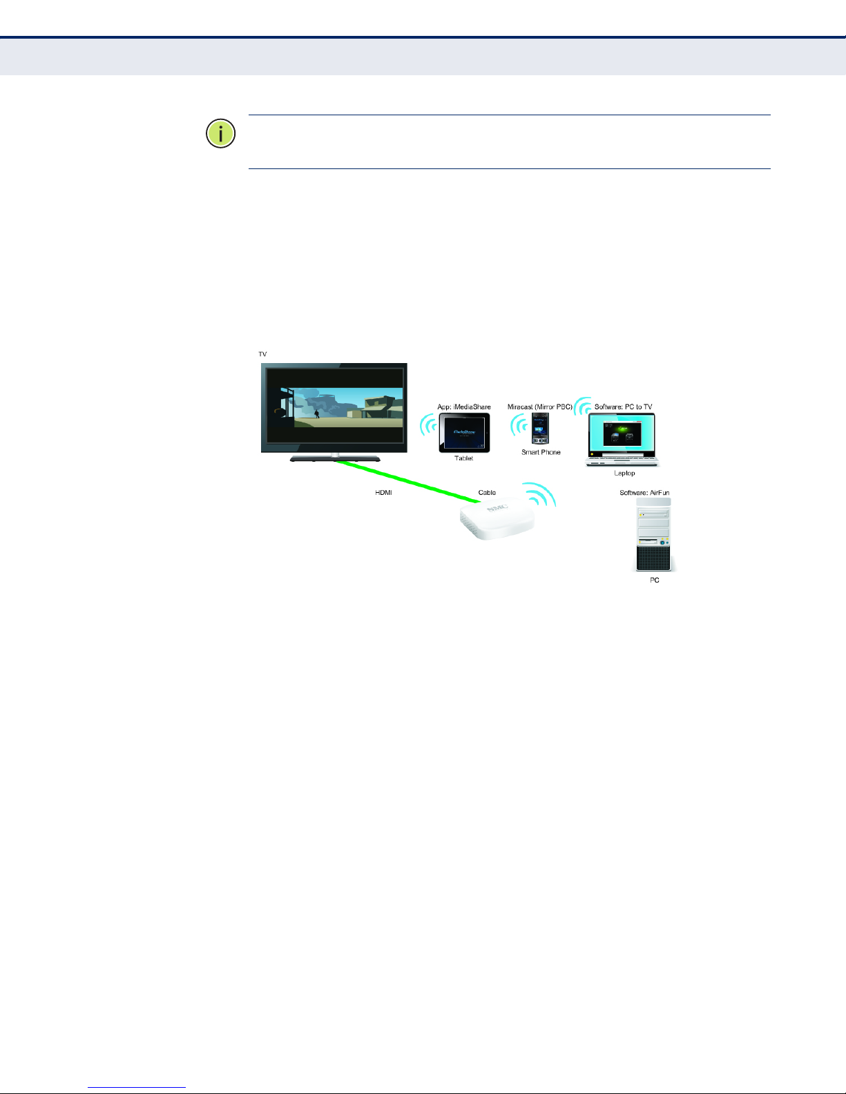
■
To use your SMCWTVA100 without an Internet connection (no
bridge, see Figure 7 on page 24), select “Virtual AP only” (default
setting). Click Apply and no further steps are necessary.
You are now ready to use the SMCWTVA100 in the Virtual AP
(stand-alone) configuration. Go to “Operation Modes” on page 45
for procedures on how to screencast.
Figure 7: Stand-Alone Connection Setup
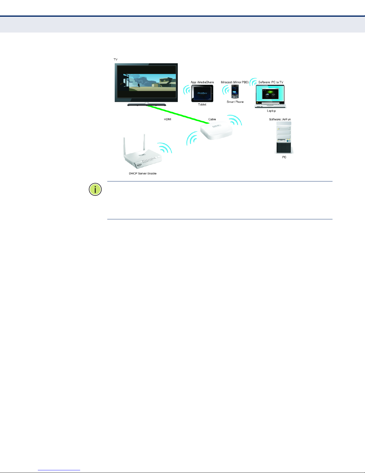
7. (Note: Bridge to Wireless only as shown in Figure 8)
Click the “Scan AP” button and click to select the 802.11 wireless
access point that you would like to bridge the internet from.
The SMCWTVA100 will restart and connect to the wireless AP that you
selected, giving you both screencast and Internet connectivity. No
further steps are necessary you are now ready to use the
SMCWTVA100 in the Bridge to Wireless configuration. Go to “Operation
Modes” on page 45 for procedures on how to screencast.
– 24 –
C
HAPTER
Connect a Device to the SMCWTVA100
Figure 8: Bridge to Wireless Connection Setup
N
OTE
:
The device will receive a new IP address from the wireless AP that it
3
| Installation Guide
connects to. Use that new IP address to log into the device from your web
browser. The new address and URL will be shown on the initial screen that
is output from the HDMI connection to a display device.
8. (Note: Bridge to Ethernet only, as shown in Figure 9)
Connect an RJ-45 Ethernet cable from the device’s RJ-45 port to a
suitable Internet connection and then click Apply in the Quick Settings
menu with Bridge To Ethernet selected in the drop-down menu.
The SMCWTVA100 will reboot to receive a new IP address over the
wired internet connection. No further steps are necessary you are now
ready to use the SMCWTVA100 in the Bridge to Ethernet configuration.
Go to “Operation Modes” on page 45 for procedures on how to
screencast.
– 25 –
 Loading...