

SMC Networks VF1000 Series, VF3000 Series, VF5000 Series Installation And Maintenance Manual
No. VF1000(V200)-TFM121**
Installation and Maintenance Manual
5 port solenoid valve
Series VF1000/3000/5000
1 Safety Instructions
This manual contains essential information for the protection of users and
others from possible injury and/or equipment damage.
• Read this manual before using the product, to ensure correct handling,
and read the manuals of related apparatus before use.
• Keep this manual in a safe place for future reference.
• These instructions indicate the level of potential hazard by label of
“Caution”, “Warning” or “Danger”, followed by important safety
information which must be carefully followed.
• To ensure safety of personnel and equipment the safety instructions in
this manual and the product catalogue must be observed, along with
other relevant safety practices.
Caution
Indicates a hazard with a low level of risk, which if not
avoided, could result in minor or moderate injury.
Warning
Indicates a hazard with a medium level of risk, which
if not avoided, could result in death or serious injury.
Danger
Indicates a hazard with a high level of risk, which if
not avoided, will result in death or serious injury.
Warning
• The compatibility of pneumatic equipment is the responsibility of the
person who designs the pneumatic system or decides its specifications.
Since the products specified here can be used in various operating
conditions, their compatibility with the specific pneumatic system must
be based on specifications or after analysis and/or tests to meet specific
requirements.
• Only trained personnel should operate pneumatically operated
machinery and equipment.
Compressed air can be dangerous if an operator is unfamiliar with it.
Assembly, handling or repair of pneumatic systems should be performed
by trained and experienced personnel.
• Do not service machinery/equipment or attempt to remove
components until safety is confirmed.
1) Inspection and maintenance of machinery/equipment should only be
performed after confirmation of safe locked-out control positions.
2) When equipment is to be removed, confirm the safety process as
mentioned above. Switch off air and electrical supplies and exhaust all
residual compressed air in the system.
3) Before machinery/equipment is re-started, ensure all safety measures
to prevent sudden movement of cylinders etc. (Supply air into the
system gradually to create back pressure, i.e. incorporate a soft-start
valve).
• Do not use this product outside of the specifications. Contact SMC
if it is to be used in any of the following conditions:
1) Conditions and environments beyond the given specifications, or if
the product is to be used outdoors.
2) Installations in conjunction with atomic energy, railway, air navigation,
vehicles, medical equipment, food and beverage, recreation equipment,
emergency stop circuits, press applications, or safety equipment.
3) An application which has the possibility of having negative effects on
people, property, or animals, requiring special safety analysis.
Caution
• Ensure that the air supply system is filtered to 5 microns.
2 Specifications
Refer to the operation manual for this product.
2.1 Specifications
Valve specifications
Fluid
Air
2 position single/3 position
0.15 to 0.7 MPa
Standard
2 position double
0.1 to 0.7 MPa
2 position single/3 position 0.15 to 1.0 MPa
Operating
pressure
range
High
pressure
2 position double 0.1 to 1.0 MPa 0.2
Ambient and fluid temperature -10 ~ 50 °C (No freezing)
Series VF1000 VF3000 VF5000
2 position single /
2 position double
10 Hz 10 Hz 5 Hz
Maximum operating
frequency
3 position - 3 Hz 3 Hz
Manual override
Non-locking push type, Push turn
locking slotted type, Push turn locking
lever type
Pilot exhaust method
Individual exhaust.
Common exhaust for main valve and
pilot valve (except VF1000 series)
Lubrication
Not required
Mounting position
Unrestricted
Impact / Vibration resistance
300/50 m/s²
(1)
Protection structure
Dust proof (G,H,L,M : IP40)
(D,Y,T : IP65*)
Table 1
Note)
Impact resistance: No malfunction occurred when it was tested with a
drop tester in the axial direction and at right angles to the main valve &
armature; in both energised & de-energised states and for every time in
each condition (Values at the initial period.)
Vibration resistance: No malfunction occurred in a one-sweep test
between 45 and 2000 Hz. Tests are performed at both energised and deenergised states in the axial direction and at right angles to the main valve
& armature. (Valves at the initial period.)
*Based on IEC60529. Compliance to IP65 is limited to the common
exhaust option.
Solenoid Specifications
Grommet (G),(H),
L plug connector (L),
M plug connector (M)
DIN terminal (D),
DIN (EN175301-803)
terminal (Y),
Conduit terminal (T)
Electrical entry
G,H,L,M D,Y,T
DC 24,12 V Coil rated
voltage
AC (50/60 Hz) 100,110,200,220,240
Allowable voltage fluctuation ±10% rated voltage
1,2,3
Standard
1.5 W
(With indicator light: 1.55 W)
1.5 W
(With indicator light: 1.75 W)
DC
Power saving
type
0.55 W
(With indicator light only)
0.75 W
(With indicator light only)
100V
110V [115 V]
200V
220V [230 V]
Power
Consumption
AC
240V
1.55 VA
(With indicator light: 1.7 VA)
Surge voltage suppressor
Diode
(Non-polar type is varistor)
Indicator light LED
LED
(Neon bulb when AC)
Table 2
1) In common between 110 VAC and 115 VAC, and between 220 VAC and
230 VAC.
2) For 115 VAC and 230 VAC, the allowable voltage is -15% ~ +5% of
rated voltage.
3) S, Z and T type (with power saving circuit), should be used with the
following allowable voltage fluctuation range due to a voltage drop caused
by the internal circuit.
24 VDC: -7% to +10%
12 VDC: -4% to +10%
2 Specifications (continued) 3 Installation (Continued
alves, tighten as follows:
C fitting, etc.
Note r the
) W
2) T
the proper tightening torques shown below.
・m)
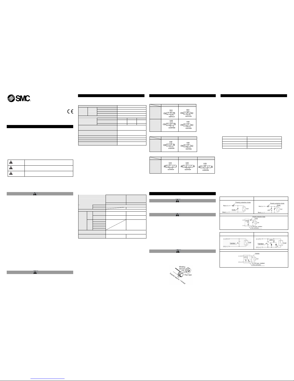
2.2 Symbol
Body ported
Single Double
VF1000
VF3000
VF5000
Base mounted
Single Double
VF3000
VF5000
Body ported / Base mounted
Closed centre Exhaust centre Pressure centre
VF3000
VF5000
Figure 1
3 Installation
3.1 Installation
Warning
• Do not install the product unless the safety instructions have been read
and understood.
3.2 Environment
Warning
• Do not use in an environment where corrosive gases, chemicals, salt
water or steam are present.
• Do not use in an explosive atmosphere.
• Do not expose to direct sunlight. Use a suitable protective cover.
• Do not install in a location subject to vibration or impact. Check the
product specifications.
• Do not mount in a location exposed to radiant heat.
• If it is used in an atmosphere where there is possible contact with water
droplets, oil, weld spatter, etc., exercise preventative measures.
• When the solenoid valve is mounted in a control panel or its energised
for a long time, make sure that the ambient temperature is within the
specification of the valve.
3.3 Piping
Caution
• Before piping make sure to clean up chips, cutting oil, dust etc.
• When installing piping or fittings, ensure sealant material does not enter
inside the port. When using seal tape, leave 1 thread exposed on the
end of the pipe/fitting.
• Tighten fittings according to appropriate tightening torque.
Figure 2
)
3.4 Con nection of fittings
When screwing fittings into v
(1) Follow the procedures belo
w when installing an SM
1) M5
After tightening the fitting by hand, use a wrench to tighten the fitting an
additional approximately 1/6 turn. However, if miniature fittings are
used, tighten an additional 1/4 turn with a tightening tool after
tightening by hand.
) If tightened excessively, the thread of the product may break o
gasket may defor
m. If tightened insufficiently, the thread of the
product may become loose. In either case, air leakage can occur.
hen fittings other than SMC fittings are used, follow the instructions of
(2
the respective fitting manufacturer.
hreads
Fasten with
Connection thread Tightening torque (N
1/8 7 to 9
1/4 12 to 14
3/8 22 to 24
1/2 28 to 30
Table 3
.5 Con nection of piping to products
uction manual to avoid mistakes
.6 Precauti ons on Design <DC>
□
With light/surge voltage suppressor (□Z)
3
When piping to a product, refer to its instr
regarding the supply port, etc.
3
・ Polar type
oltage suppressor ( S) With surge v
Grommet/L,M plug connecter
With light/surge voltage suppressor (□Z) DIN terminal/Conduit terminal
・Non-polar type
suppressor (□R)
With light/surge voltage suppressor (□U)
With surge voltage
Grommet/L,M plug connecter
With light/surge voltage suppressor (□U) DIN terminal/Conduit terminal
Table 4
• Please connect in accordance with olarity indication. (The non-polar type
•
•
the +,- p
can be used with the connections made either way.)
Please use caution regarding the allowable voltage fluctuation because there is
approximately a 1 V drop for a valve with polarity protection (For details, refer to
the solenoid specifications for the valve.)
When wiring is done at the factory, positive (+) is red and negative (-) is black.
No. VF1000(V200)-TFM121**
3 Installation (Continued)
Power saving circuit <DC type only>
Figure 3
Please use caution regarding th ble voltage fluctuation because
rectifier circuit.
terminal
e allowa
there is approximately a 0.5 V drop for a transistor. (For details, refer to the
solenoid specifications to the each valve.)
<AC>
is no “S” option, It is already built-in to the
There
Light/surge voltage suppressor (□Z) DIN terminal/Conduit
Figure 4
3.7 Residual voltage in the surg tion circuit. e protec
Caution
• Confirm the specifications
cir contains non-ordinary diodes, a
When the surge protection cuit
residual voltage that is in proportion to the protective elements and the
rated voltage will remain. Therefore, give consideration to surge voltage
protection of the controller. The following table lists the approximate
valves for the different types surge suppressor available.
In addition to this, the type of surge suppressor affects the response time
of the valve. Please see catalogue specifications for further details.
Residual voltage
DC
Surge voltage
24 12
AC
suppressor
S,Z Approx. 1 V Ap 1V prox.
R,U Approx. 32 V 47 V Approx. -
Table 5
3.8 Leakage voltage
Caution
ce (surge su is used for the protection of
Figure 5
AC coil: 8% or less of rated voltag
ous energisation
• Voltage leakage.
When a C-R devi
switching device, note tha
ppressor)
t voltage leakage will be increased by passing
voltage leakage through C-R device. Therefore, select circuit or device
which can limit residual voltage leakage to following value. And for
recovery failure due to voltage leakage, bleeder resistance should be
placed. For further information of bleeder resistance, contact SMC.
e
DC coil: 3% or less of rated voltage
3.9 Extended periods of continu
Caution
• Continuous energisation of the xtendevalve for e d periods of time may
•
have an adverse effect on the solenoid valve performance and the
peripheral equipment due to temperature rises caused by the heat
generation of the coil. Consult with SMC if valves will be continuously
energised for extended periods of time, or if the energised period per
day will be longer than the de-energised period. Use either DC
specification or power saving type.
When solenoid valves are mounted in a control panel, take measures
against radiation in order to ke
ep the valve temperature within the
specified range. Use special caution when three or more stations
sequentially aligned on the manifold are continuously energised since
this will cause a drastic temperature rise.
3 Installation (Continued)
3.10 Manual override operation
Warning
Without an electric signal for the solenoid valve the manual override is
used for switching the main valve.
When the manual override is operated, connected equipment will be
actuated. Confirm safety before operating.
■ Non-locking push type
■Push-turn locking slotted type [D type]
■Push-turn lever locking type [E type]
Figure 6
Caution
When locking the manual override on the push-turn locking types (D or E
type), be sure to push it down before turning. Turning without first
pushing it down can cause damage to the manual override and other
trouble such as air leakage, etc. [Torque : Less than 0.1N・m]
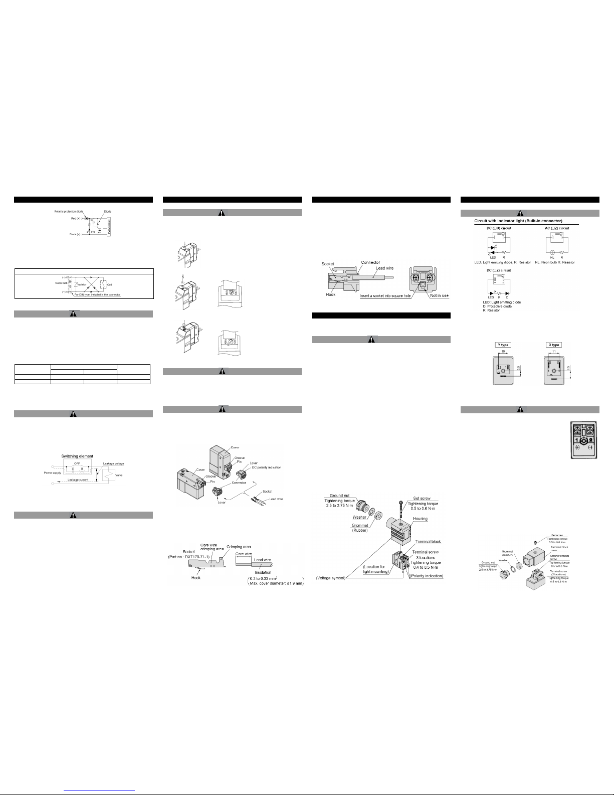
11 How to Use Plug Connector
3.
Caution
1. Attaching and detaching conn
connector unit between your
•
Figure 7
2. Crimping connection of lead socket.
rt the ends of the core
Figure 8
ectors
nd
• To attach a connector, hold the lever a
fingers and insert straight onto the pins of the solenoid valve so that the
lever’s pawl is pushed into the groove and locks.
To detach a connector, remove the pawl from the groove by pushing the
lever downward with your thumb, and pull the connector straight out.
wire and
Strip 3.2 to 3.7 mm at the end of lead wires, inse
wires evenly into the sockets, and then crimp with a crimping tool. When
this in done, take care that the coverings of the lead wires do not enter
the core wire crimping area.
3 Installation (Continued)
wires with sockets
es of the connector (+,- indication),
•
nnector, pull out the lead wire while
3. Attaching and detaching lead
• Attaching
ockets into the square hol
Insert the s
and continue to push the sockets all the way in until they lock by
hooking into the seats in the connector. (When they are pushed in, their
hooks open and they are locked automatically.) Then, confirm that they
are locked by pulling lightly on the lead wires.
Detaching
a socket from a co
To detach
pressing the socket’s hook with a stick with a thin tip (approx. 1 mm).
If the socket needs to used again, first spread the hook outward.
Figure 9
4 Settings and Programming
(based on IEC60529) are protected against
4.1 How to Use DIN terminal
Products with IP65 enclosures
dust and water, however, these products cannot be used in water.
Caution
Connection
set screw and pull the connector out of the solenoid valve
3.
4.
abtyre cords carefully because if
C
ck and housing, the cord entry direction
m
2
, 2-core or 3-core, equivalent to JIS C 3306.
Ltd.
1. Loosen the
terminal block.
2. After removing the set screw, insert a flat head screwdriver, etc. into the
notch on the bottom of the terminal block and pry it open, separating the
terminal block and the housing.
Loosen the terminal screws on the terminal block, insert the core of the
lead wire to the terminal, and attach securely with the terminal screws.
In case of a DC surge voltage suppressor attached type (polar: S and Z
types), connect wires corresponding to the polarity (+ or -) that is printed
on the terminal block.
Tighten the ground nut and fix the wire.
In the case of connecting wires, select c
those out of the specified range (Ø4.5 to Ø7) are used, it will not be able
to satisfy IP65 (enclosure). Tighten the ground nut and set screw within
the specified range of torque.
hanging the entry direction
lo
After separating the terminal b
can be changed by attaching the housing in the opposite direction.
* Be careful not to damage elements, etc. with the cord’s lead wires.
Caution
nd pull out the connector vertically without tilting to one side.
Plug in a
Compatible cable
Ø7
Cord O.D.: Ø4.5 to
(Reference) 0.5 to 1.5 m
Applicable crimped terminals
cified in JIS C 2805.
O-terminal: R1.25-4M that is spe
Y-terminal: 1.25-3L, which is released by JST Mfg. Co.,
Bar terminal: Size 1.5 or shorter.
Figure 10
4 Settings and Programming (Continued)
4.2 Circuit Diagram with Light/Surge Voltage Suppressor
Caution
Push down on the manual
override button with a small
screwdriver until it stops.
Release the screwdriver and
the manual override will
return.
Locked position
While pressing, turn in
the direction of the arrow
(90° clockwise). If it is
not turned, it can be
operated the same way
as the non-locking type.
Figure 11
4.3 DIN (EN175301-803) terminal
Y type DIN type terminal corresponds to the DIN connector with terminal
pitch 10 mm, which complies with EN175301-803B. Since the terminal
pitch is different from the D type DIN connector, these two types are not
interchangeable.
While pressing, turn it
the direction of the
arrow. If it is not
turned, it can be
operated the same
way as the nonlocking type.
Locked position
Figure 12
4.4 How to Use Conduit Terminal
Caution
Connection
1. Loosen the set screw and remove the terminal block
cover from the terminal block.
2. Loosen the terminal screws of the terminal block,
insert the core of the lead wire to the terminal, and
attach securely with the terminal screws.
In case of a DC surge voltage suppressor attached
type (S and Z type with limited polarity), care must
be taken that the positive and negative wires are
connected according to the figure on the right.
3. Tighten the ground nut and fix the cable.
In the case of connecting wires, select cabtyre cords carefully because if
those out of the specified range (Ø4.5 to Ø7) are used, it will not be able to
satisfy IP65 (enclosure). Tighten the ground nut and set screw within the
specified range of torque.
Compatible cable
Cord O.D. : Ø4.5 to Ø7
(Reference) 0.5 to 1.5 mm
2
, 2-core or 3-core, equivalent to JIS C 3306.
Applicable crimped terminals
O-terminal : Equivalent to R1.25-3 that is specified in JIS C 2805.
Y-terminal : Equivalent to 1.25-3, which is released by JST Mfg. Co., Ltd.
* Use O terminal when a ground terminal is used.
Figure 14
Figure 13
 Loading...