

SMC Networks VDW 10, VDW 20, VDW 30, VDW200, VDW300 Installation And Maintenance Manual
2 INTENDED CONDITIONS OF USE
2.1 Standard specifications VDW 10/20/30
Valve specifications
Note 1) Consult SMC when used under conditions which may cause condensation on the
exterior of the product.
Note 2) When used with pure water, select "L" (stainless steel, FKM) for the material
type.
Note 3) Since AC coil specifications include a rectifying device, there is no difference in
power consumption for starting and holding. In case of 110/220VAC, VDW10
is 3W and VDW20/30 is 3.5W.
Note 4) Vibration resistance … No malfunction when tested with one sweep of 5 to 200Hz
in the axial direction and at a right angle to the armature, in both energized and
deenergized.states. Impact resistance … No malfunction when tested with a
drop tester in the axial direction and at a right angle to the armature, one time
each in energized and deenergized states.
Note 5) Consult SMC regarding drip-proof specifications (equivalent to IP54).
2.2 Piping
When piping to an N.O. port, be sure to perform piping work while holding the socket
with a wrench or other tool.
2.3 Circuit Symbols
3 INSTALLATION
WARNING
Do not install unless the safety instructions have been read and understood.
3.1 Environment
WARNING
Do not use in an environment where the product is directly exposed to corrosive
gases, chemicals, salt water, water or steam.
Do not use in an explosive atmosphere.
The product should not be exposed to prolonged sunlight. Use a protective cover.
Do not mount the product in a location where it is subject to strong vibrations
and/or shock. Check the product specifications for above ratings.
Do not mount the product in a location where it is exposed to radiant heat.
Read this manual before using this product.
The information within this document is to be used by pneumatically trained
personnel only.
For future reference, please keep manual in a safe place.
This manual should be read in conjunction with the current catalogue.
1 SAFETY
1.1 General recommendation
These safety instructions are intended to prevent a hazardous situation and/or
equipment damage. These instructions indicate the level of potential hazard by label of
"Caution", "Warning" or "Danger". To ensure safety, be sure to observe ISO4414
(Note1), JIS B 8370 (Note2) and other safety practices.
Note 1:ISO 4414:Pneumatic fluid power - General rules relating to systems.
Note 2:JIS B 8370:Pneumatic system axiom.
WARNING
• The compatibility of pneumatic equipment is the responsibility of the person
who designs the pneumatic system or decides its specifications.
Since the products specified here are used in various operating conditions, their
compatibility for the specific pneumatic system must be based on specifications or
after analysis and/or tests to meet your specific requirements.
• Only trained personnel should operate pneumatically operated machinery
and equipment.
Compressed air can be dangerous if an operator is unfamiliar with it. Assembly,
handling or repair of pneumatic systems should be performed by trained and
experienced operators.
• Do not service machinery/equipment or attempt to remove components
until safety is confirmed.
Inspection and maintenance of machinery/equipment should only be performed
after confirmation of safe locked-out control positions.
When equipment is to be removed, confirm the safety process as mentioned
above. Switch off air and electrical supplies and exhaust all residual compressed
air in the system.
Before machinery/equipment is re-started, ensure all safety measures to prevent
sudden movement of cylinders etc. (Bleed air into the system gradually to create
backpressure, i.e. incorporate a soft-start valve).
• Contact SMC if the product is to be used in any of the following conditions:
Conditions and environments beyond the given specifications, or if product is used
outdoors.
Installations on equipment in conjunction with atomic energy, railway, air
navigation, vehicles, medical equipment, food and beverage, recreation
equipment, emergency stop circuits, press applications, or safety equipment.
An application, which has the possibility of having negative effects on people,
property, or animals, requiring special safety analysis.
CAUTION:
Ensure that the air supply system is filtered to 5 micron.
1.2 Conformity to standard
This product is certified to and complies with the following standards:
3.2 Piping
CAUTION
Before piping make sure to clean up chips, cutting oil, dust etc.
When installing piping or fitting into a port, ensure that sealant material does not
enter the port inside. When using seal tape, leave 1.5 to 2 threads exposed on the
end of pipe/fitting.
CAUTION
The maximum operating pressure differential differs depending on the flow direction of
the fluid. If the pressure differential at each port exceeds the values in the table below,
valve leakage may occur.
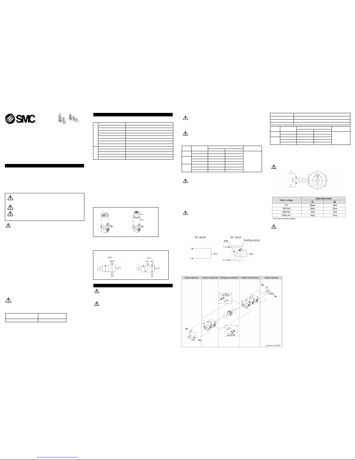
3.3 Electrical connection
CAUTION:
When DC power is connected to a solenoid valve equipped with light and/or surge
voltage suppressor, check for polarity indications.
For polarity indications:
•• No diode to protect polarity: if polarity connection is wrong, the diode in the
valve or switching device at control equipment or power supply may be
damaged.
•• With diode to protect polarity: if polarity connection is wrong, the valve does
not switch.
3.4 Wiring
CAUTION:
As a rule, use electrical wire of 0.5 to 1.25mm2 or more. Furthermore, do not allow
excessive force to be applied to the lines.
Use electrical circuits which do not generate chattering in their contacts.
Use voltage which is within
±10%
of the rated voltage, In cases of a DC power
supply where emphasis is placed on responsiveness, stay within
±5%
of the rated
value. The voltage drop is the value in the lead wire section connecting the coil.
Installation and Maintenance Manual
Series VDW 10/20/30: 2 port, VDW200/300: 3 port
Compact Direct Operated Solenoid Valve
for Water and Air
CAUTION: Operator error could result in injury or equipment
damage.
WARNING: Operator error could result in serious injury or loss of life.
DANGER: In extreme conditions, there is a possible result of
serious injury or loss of life.
X
Note1) Indicate the maximum operating pressure differential between ports 2 and 3.
Note2) When applying pressure from port 2, be careful to avoid vibration and impacts
etc.
Note3) For low vacuum specifications, the operating pressure range is 1 Torr
(1.33 102Pa) to 1.0Mpa.
The grommet is the only available option.
CAUTION
3.5 Mounting
WARNING
If air leakage increases or equipment does not operate properly, stop
operation.
After mounting is completed, comfirm that it has been done correctly by
performing a suitable function test.
Do not apply external force to the coil section.
When tightening is performed, apply a wrench or other tool to the outside of the
piping connection parts.
Do not warm the coil assembly with a heat insulator, etc.
Use tape and heaters, etc., for freeze prevention on the piping and body only.
They can cause the coil to burn out.
Secure the product except in the case of steel piping and copper fittings.
Avoid sources of vibration, or set the arm from the body to the minimum
length so that resonance will not occur.
Instruction manual
Mount the product after reading the manual carefully and understanding its
contents. Also keep the manual where it can be referred to as necessary.
Painting and coating
Warning and specifications printed or pasted on the product should not be
erased, removed or covered up.
3.6 Manifold Mounting
Manifold additions
1. Install a passage pipe assembly in between the manifold bases to be
added.
2. Connect the respective manifold bases with a connecting plate
assembly. (Tightening torque: 0.9±0.1N.m)
3. Attach brackets to the manifold bases. {When equipped with
brackets} (Tightening torque: 0.9±0.1N.m)
VDW - TFI29GB
EMC Directive 89/336/EEC EN61000-6-2
EN55011
Low Voltage Directive 93/68/EEC DIN VDE 0580
Valve construction Direct operated poppet
Fluid Note 2) Water (except waste water or agricultural water), Air, Low vacuum
Withstand pressure Mpa 2.0
Ambient temperature °C -10 to 50
Fluid temperature °C 1 to 50 (with no freezing)
Environment Location without corrosive or explosive gases
Valve leakage cm3/min 0 (with water pressure) 1 (with air pressure)
Mounting orientation Unrestricted
Vibration/Impact m/s2 Note 4) 30/150
Rated voltage 24VDC, 12VDC, 100VAC, 110VAC, 200VAC, 220VAC (50/60Hz)
Allowable voltage fluctuation % ±10% of rated voltage
Coil insulation type Class B
Enclosure Note 5) Dust proof (equivalent to IP40)
Power consumption W Note 3) 2.5 (VDW10), 3 (VDW20/30/200/300)
Valve specifications
Coil
specifications
Lead wire
OUT
IN
N.O.
Socket
Cover
Lead wire
N.C.
IN
Thread Appropriate tightening torque (Nm)
M5 By hand + 1/6 turn with the wrench (1/4 turn for miniature fittings)
Rc 1/8 7 to 9
Rc 1/4 12 to 14
Model Orifice size mm Operating pressure
Pressure port 1 Pressure port 2
(2)
range Mpa
(3)
VDW10 ø1 0.9 0.4
ø1.6 0.4 0.2
VDW20 ø1.6 0.7 0.2
ø2.3 0.4 0.1 0 to 1.0
ø3.2 0.2 0.05
VDW30 ø2 0.8 0.2
ø3 0.4 0.1
ø4 0.2 0.05
Maximum operating pressure differential Mpa
Model Orifice size mm Operating pressure
Pressure port 1 Pressure port 2,3
(1)(2)
range Mpa
(3)
VDW200 ø1 0.9 0.3
ø1.6 0.7 0.1
VDW300 ø2 0.8 0.2
ø3 0.4 0.1 0 to 1.0
ø4 0.2 0.05
Maximum operating pressure differential Mpa
Page 1 of 2
N.C.
VDW 10/20/30 VDW 200/300
1
2

4 MAINTENANCE
WARNING:
Not following proper procedures could cause the product to malfunction and could
lead to damage to the equipment or machine.
If handled improperly, compressed air can be dangerous. Assembly, handling and
repair of pneumatic system should be performed by qualified personnel only.
Drain: remove condensate from the filter bowl on a regular basis.
Shut-down before maintenance: before attempting any kind of maintenance make
sure the supply pressure is shut off and all residual air pressure is released from
the system to be worked on.
Start-up after maintenance: apply operating pressure and power to the equipment
and check for proper operation and possible air leaks. If operation is abnormal,
please verify product set-up parameters.
Do not make any modification to the product.
Do not disassemble the product, unless required by installation or maintenance
instructions.
After removing the socket with a wrench, etc., lift off the plate, wave washer and cover,
and replace the coil assembly. After replacing the coil, first tighten the socket by hand
while holding down the plate and wave washer, and then tighten it further with a torque
of 0.8 to 1N·m.
Precautions when attaching and removing the socket.
Be careful that the O-ring installed on the bottom (plate side) of the socket does
not fall out or become chewed up, etc.
Be sure to hold the body with a wrench, etc., and tighten the socket within the
tightening torque range given above. if excessive torque is applied, there is a
danger of damaging the threads.
After removing the socket with a wrench, etc., lift off the plate, wave washer and cover,
and replace the coil assembly. After replacing the coil, first tighten the socket by hand
while holding down the plate and wave washer, and then tighten it further with a torque
of 0.8 to 1N.m.
Precautions when attaching and removing the socket
Be careful that the O-ring installed on the bottom (plate side) of the socket does
not fall out or become chewed up, etc.
Be sure to hold the body with a wrench, etc., and tighten the socket within the
tightening torque range given above. If excessive torque is applied, there is a
danger of damaging the threads.
5 LIMITATIONS OF USE
Leakage
Particularly when using a resistor in parallel with a switching element and using a C-R
element (surge voltage suppressor) to protect the switching element, take note that
leakage current will flow through the resistor and C-R element, etc., creating a danger
that the valve may not shut OFF.
Low temperature operation
The valve can be used at ambient temperatures as low as -10°C, but take measures to
prevent freezing or solidification of impurities, etc.
When used in cold areas with water, etc., adopt freeze prevention measures such as
draining the water from pipelines after pump operation has been stopped. If warmed
with a heater, etc., avoid the coil unit. Also, implement warming or other freeze
prevention measures for the body.
Page 2 of 2
VDW - TFI29GB
6 EUROPEAN CONTACT LIST
6.1 SMC Corporation
Country Telephone Country Telephone
Austria (43) 2262-62 280 Italy (39) 02-92711
Belgium (32) 3-355 1464 Netherlands (31) 20-531 8888
Czech Republic (420) 5-414 24611 Norway (47) 67 12 90 20
Denmark (45) 70 25 29 00 Poland (48) 22-548 50 85
Finland (358) 9-859 580 Portugal (351) 22 610 89 22
France (33) 1-64 76 1000 Spain (34) 945-18 4100
Germany (49) 6103 4020 Sweden (46) 8 603 12 00
Greece (30) 1- 342 6076 Switzerland (41) 52-396 3131
Hungary (36) 23 511 390 Turkey (90) 212 221 1512
Ireland (353) 1-403 9000 United Kingdom (44) 1908-56 3888
6.2 Websites
SMC Corporation www.smcworld.com
SMC Europe www.smceu.com
3 port valve
2 port valve
 Loading...