

SMC Networks VCHR30 Series Installation And Maintenance Manual
VCHR30-TFR04
Page 1of 2
Installation and Maintenance Manual
Direct Operated Regulator – 6.0 MPa
Relieving type.
Series VCHR30
1 Safety Instructions
This manual contains essential information for the protection of users and
others from possible injury and/or equipment damage.
• Read this manual before using the product, to ensure correct handling,
and read the manuals of related apparatus before use.
• Keep this manual in a safe place for future reference.
• These instructions indicate the level of potential hazard by label of
“Caution”, “Warning” or “Danger”, followed by important safety
information which must be carefully followed.
• To ensure safety of personnel and equipment the safety instructions in
this manual and the product catalogue must be observed, along with
other relevant safety practices.
Caution
Indicates a hazard with a low level of risk, which if not
avoided, could result in minor or moderate injury.
Warning
Indicates a hazard with a medium level of risk, which
if not avoided, could result in death or serious injury.
Danger
Indicates a hazard with a high level of risk, which if
not avoided, will result in death or serious injury.
Warning
• The compatibility of pneumatic equipment is the responsibility of the
person who designs the pneumatic system or decides its specifications.
Since the products specified here can be used in various operating
conditions, their compatibility with the specific pneumatic system must
be based on specifications or after analysis and/or tests to meet specific
requirements.
• Only trained personnel should operate pneumatically operated
machinery and equipment.
Compressed air can be dangerous if an operator is unfamiliar with it.
Assembly, handling or repair of pneumatic systems should be performed
by trained and experienced personnel.
• Do not service machinery/equipment or attempt to remove
components until safety is confirmed.
1) Inspection and maintenance of machinery/equipment should only be
performed after confirmation of safe locked-out control positions.
2) When equipment is to be removed, confirm the safety process as
mentioned above. Switch off air and electrical supplies and exhaust all
residual compressed air in the system.
3) Before machinery/equipment is re -started, ensure all safety measures
to prevent sudden movement of cylinders etc. (Supply air into the system
gradually to create back pressure, i.e. incorporate a soft-start valve).
• Do not use this product outside of the specifications. Contact SMC
if it is to be used in any of the following conditions:
1) Conditions and environments beyond the given specifications, or if the
product is to be used outdoors.
2) Installations in conjunction with atomic energy, railway, air na vigation,
vehicles, medical equipment, food and beverage, recreation equipment,
emergency stop circuits, press applications, or safety equipment.
3) An application which has the possibility of having negative effects on
people, property, or animals, requiring special safety analysis.
Caution
• Ensure that the air supply system is filtered to 5 m or less.
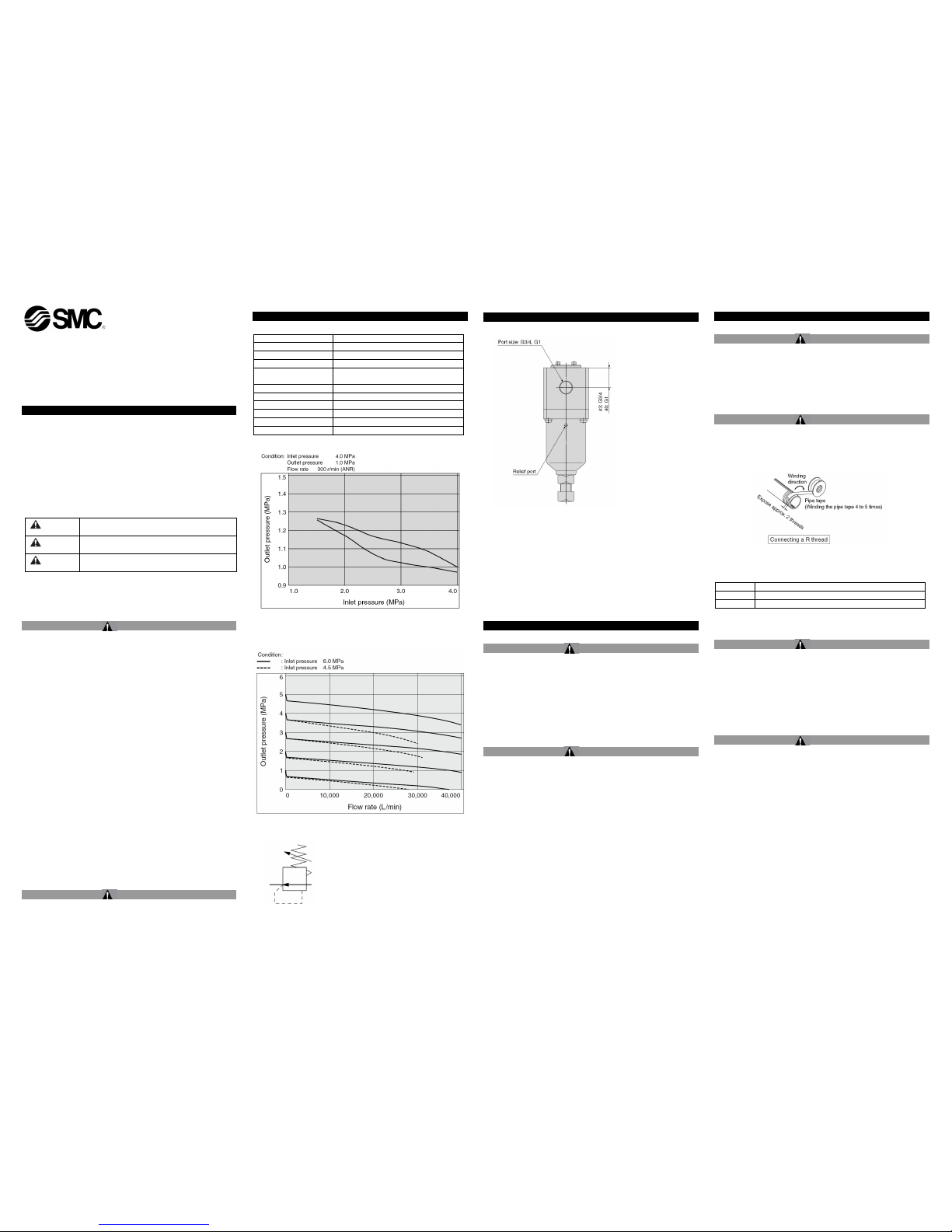
2 Specifications
2.1 General specifications
Regulator construction
Piston type
Valve material
Polyurethane elastomer
Relief mechanism
Relieving type
Port size
G3/4, G1
Thread type
Conforming to ISO 1179-1 for
pneumatic/hydraulic G thread
Fluid
Air
Max. operating pressure
6.0 MPa
Setting pressure
0.5 to 5.0 MPa
Fluid temperature
-5 to 60°C
Ambient temperature
-5 to 60°C
Weight
4.4 kg
2.2 Pressure Characteristics
Figure 1
2.3 Flow Characteristics
Figure 2
2.4 Circuit Symbol
2 Specifications (continued)
2.5 Ports
Figure 3
2.6 PED status
Pressure Equipment Directive 97/23/EC
Equipment: Pressure accessory
Fluid Air (group 2 gas)
PS: 60 bar
DN: 14 mm
Classification: SEP
This product meets the SEP (Sound Engineering Practice) requirements of
the PED as a pressure accessory.
3 Installation
3.1 Installation
Warning
• Do not install the product unless the safety instructions have been read
and understood.
• Do not use compressed air that contains chemicals, synthetic oils
including organic solvents, salt or corrosive gasses, etc. as these can
cause damage or malfunction.
• Compressed air that contains a large amount of drainage can cause
malfunction of pneumatic equipment such as regulators. Therefore take
appropriate measures to ensure air quality, such as by providing an
aftercooler, air dryer or water separator.
3.2 Mounting
Caution
• Confirm the ‘IN ‘ and ‘OUT’ ports showing the inle t/outlet of the air flow,
or the arrow mark, before connection. Reverse connection will result in
malfunctions.
• Provide adequate space above, beneath and in front of the product, for
maintenance or operation.
• The regulator has 2 x Ø10.5 mm mounting holes;
• Air will be released from the relief/vent ports when the ‘OUT’ port
pressure is above the set point. Ensure that the air jet, volume of air and
noise does not cause a hazard. See Figure 3.
3 Installation (continued)
3.3 Environment
Warning
• Do not use in an environment where corrosive gases, chemicals, salt
water or steam are present.
• Do not use in an explosive atmosphere.
• Do not expose to direct sunlight. Use a suitable protective cover.
• Do not install in a location subject to vibration or impact. Check the
product specifications.
• Do not mount in a location exposed to radiant heat.
3.4 Piping
Caution
• Before piping make sure to clean up chips, cutting oil, dust etc.
• Pipe tape is not necessary since this product uses a pneumatic and
hydraulic purpose G thread which conforms to ISO 1179-1. When an R
(taper) thread is used, leave 1 to 2 threads at the tip exposed before
winding the piping tape around it 4 to 5 times.
Figure 4
• Tighten fittings to the specified tightening torque.
Thread
Tightening Torque N·m
G 3/4
28 to 30
G 1
36 to 38
Table 1
Warning
• When tightening piping or fittings, ensure the product is securely
supported, so that twisting or bending is not applied to the product.
• Insufficient tightening torque will cause looseness or insufficient sealing.
However, over tightening will cause damage to the thread.
• Support the external piping separately.
• If rigid piping, such as steel piping, is subject to excessive load or
transmission of vibrations from the piping side, use flexible tubing, etc.
between them to avoid it.
3.5 Lubrication
Caution
• This product has grease applied to mechanical parts at manufacture. Do
not lubricate in service as valve seals may be damaged.
VCHR30-TFR04
Page 2of 2
4 Settings
• The outlet pressure is set by rotating the adjusting bolt, at the bottom of
the regulator. SeeFigure 3.Loosen the locknut first.
• The adjusting bolt (32 mm across flats) can be rotated by a spanner,
or with a screwdriver using the Ø11mm hole in the bolt head.
Warning
• Adjust the outlet pressure while confirming the pressure gauge values on
the inlet and outlet sides.
• Over-rotating the adjusting bolt will damage the inner components of the
product.
• The set outlet pressure should be less than 85% of the inlet pressure.
• Setting the outlet pressure to more than 85% of the inlet pressure may
cause fluctuation of flow or pressure on the inlet side, resulting in
unstable operation.
• The maximum value of the set pressure range has a tolerance,
therefore, the set pressure may exceed this value.
• Tighten the locknut when adjustment is complete. The locknut is not
an anti-tamper device. Appropriate measures against foreseeable
misuse must be taken if this can cause a hazard.
Caution
• Adjust after carefully confirming the inlet pressure.
• When adjusting the outlet pressure, a torque is applied to the adjusting
bolt. Support the product separately, so that the torque force is not
transferred to the external piping.
Reference for Adjusting bolt Torque
Set pressure
1 MPa
2 MPa
3 MPa
4 MPa
5 MPa
Torque N·m
3 6 9
12
15
Table 2
• Setting the outlet pressure should be conducted by increasing the
pressure.
• Setting the outlet pressure by decreasing the pressure may result in
going below the required set pressure.
• Turning the adjusting bolt in the clockwise direction, increases the
pressure.
• Turning the adjusting bolt counter-clockwise, will decrease the outlet
pressure.
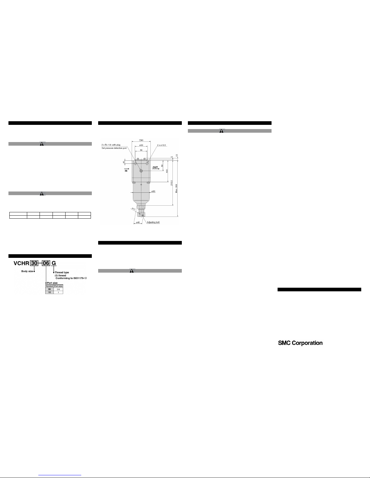
5 How to Order
6 Outline Dimensions (mm)
Figure 5
7 Maintenance
7.1 General Maintenance
• This product does not require maintenance. However the following
advice should be followed:
Ensure the proper function of the regulator is regularly
checked
Ensure there is no build-up of dirt or debris on the regulator,
especially around the vent ports and adjustment screw.
Caution
• Not following proper maintenance procedures could cause the product to
malfunction and lead to equipment damage.
• If handled improperly, compressed air can be dangero us. Maintenance
of pneumatic systems should be performed only by qualified personnel.
• Before performing maintenance, turn off the power supply and be sure to
cut off the supply pressure. Confirm that the air is released to
atmosphere.
• After installation and maintenance, apply operating pressure and power
to the equipment and perform appropriate functional and leakage tests
to make sure the equipment is installed correctly.
• Do not make any modification to the product.
• Do not disassemble the product, unless required by installation or
maintenance instructions.
8 Limitations of Use
Warning
• This product must not be used as a safety accessory as defined by the
Pressure Equipment Directive 97/23/EC.
• Install a protective device if the outlet pressure exceeding the set outlet
pressure could cause equipment damage or malfunction.
• The outlet pressure may fluctuate when the air has not been consumed
for a long time, or the product is used in a shut-off or balancing circuit on
the outlet side.
• Grease may leak into the outlet side, as it is applied to inner sliding parts
and seals.
• Do not use in circuits requiring highly precise relief sensitivity or setting
precision.
9 Contacts
AUSTRIA
(43) 2262 62280-0
LATVIA
(371) 781 77 00
BELGIUM
(32) 3 355 1464
LITHUANIA
(370) 5 264 8126
BULGARIA
(359) 2 974 4492
NETHERLANDS
(31) 20 531 8888
CZECH REP.
(420) 541 424 611
NORWAY
(47) 67 12 90 20
DENMARK
(45) 7025 2900
POLAND
(48) 22 211 9600
ESTONIA
(372) 651 0370
PORTUGAL
(351) 21 471 1880
FINLAND
(358) 207 513513
ROMANIA
(40) 21 320 5111
FRANCE
(33) 1 6476 1000
SLOVAKIA
(421) 2 444 56725
GERMANY
(49) 6103 4020
SLOVENIA
(386) 73 885 412
GREECE
(30) 210 271 7265
SPAIN
(34) 945 184 100
HUNGARY
(36) 23 511 390
SWEDEN
(46) 8 603 1200
IRELAND
(353) 1 403 9000
SWITZERLAND
(41) 52 396 3131
ITALY
(39) 02 92711
UNITED KINGDOM
(44) 1908 563888
URL :
http// www.smcworld.com (Global) http// www.smceu.com (Europe)
Specifications are subject to change without prior notice from the manufacturer.
© 2013 SMC Corporation All Rights Reserved.
 Loading...