

SMC Networks TigerSwitch series, TigerSwitch SMC6624GSSC, TigerSwitch SMC6624GT, TigerSwitch SMC6624GLSC, TigerSwitch SMC6624FMSC Installation Manual
1
SMC TigerSwitch Modules
Installation Guide
Introduction
The SMC TigerSwitch modules can be installed into the SMC6624M switch
to provide 100 Mbps and 1000 Mbps connections to other compatible
network devices.
This document describes how to install, verify, and troubleshoot the
following SMC TigerSwitch modules:
Use these modules for the following network connectivity:
■ 1000BASE-SX module—1000 Mbps operation over multimode fiber-
optic cable
■ 1000BASE-LX module—1000 Mbps operation over either single-
mode or multimode fiber-optic cable
■ 100/1000BASE-T module—1000 or 100 Mbps operation over Cate-
gory 5 or better unshielded twisted-pair (UTP) or shielded twistedpair (STP) cables
■ 100BASE-FX SC module—100 Mbps operation over multimode
fiber-optic cable
For more information on the cables used with these modules and the
supported cable lengths, see page 4.
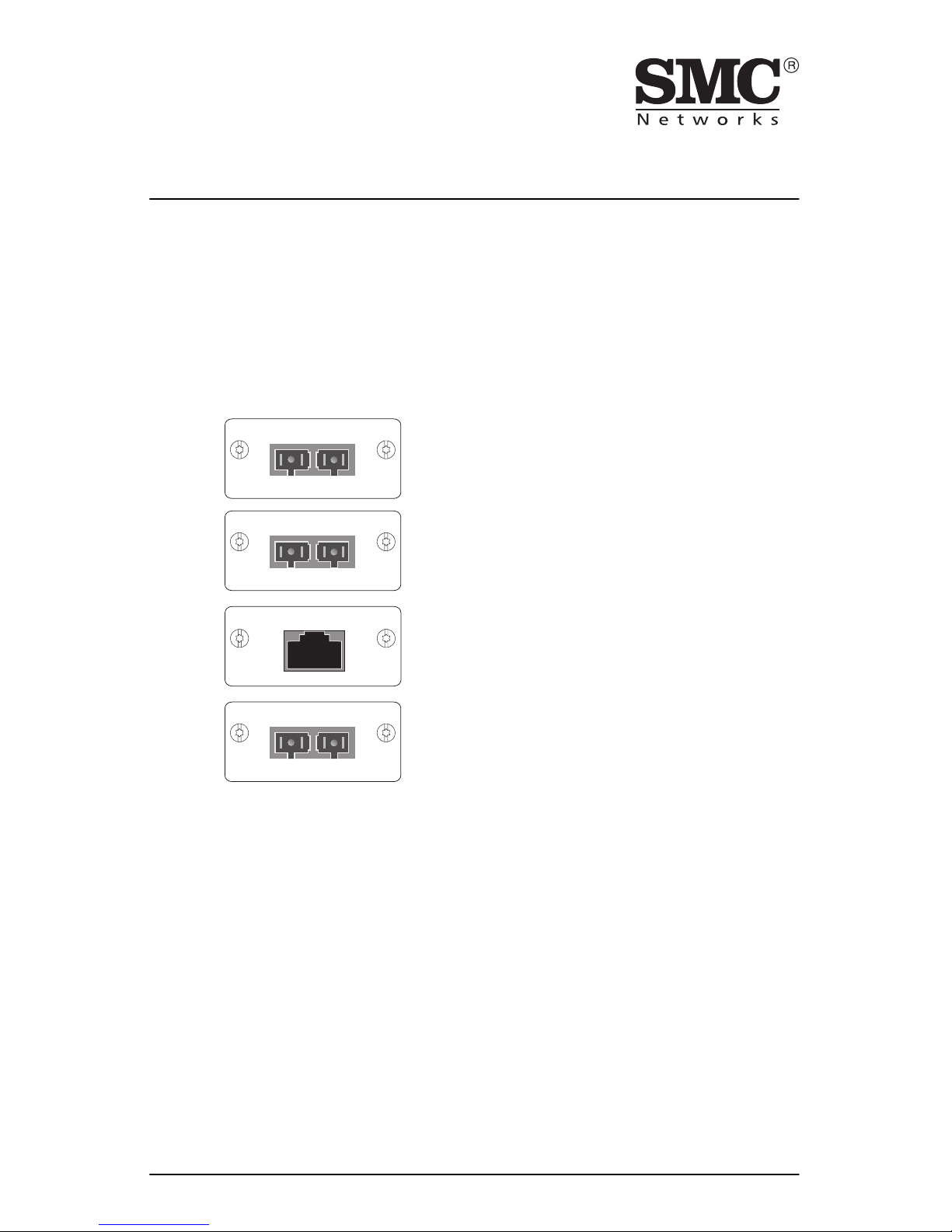
1000BASE-SX-SC
TX RX
SMC6624GSSC
1000BASE-LX-SC
TX RX
SMC6624GLSC
100BASE-FX-SC MMF
TX RX
SMC6624FMSC
100/1000BASE-T
SMC6624GT
SMC6624GSSC 1000BASE-SX module
SMC6624GLSC 1000BASE-LX module
SMC6624GT 100/1000BASE-T module
SMC6624FMSC 100BASE-FX module

2
Installation Steps
To install the SMC TigerSwitch modules, follow these steps:
1. Insert the module into an SMC6624M module slot and secure the
retaining screws.
2. Reset or reboot the SMC6624M switch.
3. Connect the network cable to the module and check the module and
network device for correct operation.
Details on these steps are provided in the rest of this document.
Installation Notes
Please read these notes before proceeding.
■ The SMC TigerSwitch modules are supported in the SMC
TigerSwitch 10/100 SMC6624M switch only. Do not try to install the
modules in any other SMC TigerSwitch devices.
■ It is not necessary to turn off power to the SMC6624M switch before
installing a module into it. You can install a module while the switch
is powered on, but you must reset or reboot the switch after installing
the module to initialize and activate it.
Please see the TigerSwitch 10/100 SMC6624M Installation Guide for more
information on installing the modules.

3
Insert the Module into the Slot
The modules are installed into the SMC6624M switch as follows:
1. Using a flat-bladed or Torx T-10 screwdriver, unscrew the two retaining
screws on the slot cover plate or existing module, and remove it from
the switch.
2. Touch a grounded, metal object (such as a powered-on switch) to
discharge any static electricity on your body, then carefully remove the
module from its protective anti-static packaging. Hold the module by
its bulkhead or edges, taking care not touch any of its board components
or metal connectors.
3. Slide the module firmly into the module slot as far as it will go. The
module should “snap” into place, and the module’s faceplate should
touch the front panel of the switch. The following illustration shows the
module being installed into the SMC6624M switch.
4. Using the flat-bladed or Torx T-10 screwdriver, tighten the retaining
screws on the module until they are secure, but be careful that you do
not overtighten the screws.
5. Reset the switch to initialize the module.
1
7
25
26
25 26
1 2 3 4 5 6 13 14 15 16 17 18
789101112192021222324
Clear
Reset
Self
Test
Fan
Status
Link
Act
Link
Act
Console
Power
Fault
loosen these screws and remove the cover plate
25
25 26
1 2 3 4 5 6 13 14 15 16 17 18
789101112192021222324
Clear
Reset
Self
Test
Fan
Status
Link
Act
Link
Act
1000BASE-SX-SC
TX RX
SMC6624GSSC
slide the module into the slot
until it snaps into place

4
Connect Network Cables to the Module Port
The network cables identified in the table below should be used with the
SMC TigerSwitch modules.
Port Type Cable Type Length Limits
Fiber-Optic Cables
1000BASE-SX 62.5/125 µm or 50/125 µm core/
cladding diameter, graded-index,
multimode fiber-optic cables that
are fitted with SC connectors—the
cables must comply with the ITU-T
G.651 and ISO/IEC 793-2 Type A1b
or A1a standards.
•62.5 µm cable:
– 160 MHz*km = 220 meters
– 200 MHz*km = 275 meters
•50 µm cable:
– 400 MHz*km = 500 meters
– 500 MHz*km = 550 meters
1000BASE-LX single-mode cables fitted with SC
connectors—the cables must
comply with the ITU-T G.652 and
ISO/IEC 793-2 Type B1 standards.
The multimode cables specified for
the 1000BASE-SX module may also
be used, but a mode conditioning
patch cord may be needed — see
“Mode Conditioning Patch Cord”
on page 8 for more information.
• single-mode cable - 5 kilometers
• multimode cable - 550 meters
100BASE-FX 62.5/125 µm or 50/125 µm core/
cladding diameter, graded-index,
multimode fiber-optic cables that
are fitted with SC connectors—the
cables must comply with the ITU-T
G.651 and ISO/IEC 793-2 Type A1b
or A1a standards.
• 2 kilometers for full-duplex
connections
• 412 meters for half-duplex
connections
Note: The SMC6624M switch does
not support half-duplex operation
for the modules.
Twisted-Pair Cables
100/
1000BASE-T
Category 5 or better, 100-ohm UTP
or STP balanced cable. For 1000
Mbps (Gigabit) operation,
Category 5E cabling or better is
recommended.
Note: For 1000 Mbps operation, all
four wire pairs are used for data
transmissions.
100 meters
Note: The 100/1000BASE-T module
is compatible with the IEEE 802.3ab
standard including the “Auto MDI/
MDI-X” feature, which allows you
to use either straight-through or
crossover twisted-pair cables for
connection go any network device
including end nodes, such as
computers, or to other switches,
hubs, and routers.

5
To connect a fiber-optic cable to
a module:
1. For fiber optic modules, remove
the plastic dust covers from the
cable connectors and from the
module port.
2. Press the connector into the jack
so that the tabs on the connector
slide into the notches in the jack
and the connector snaps securely
into place.
3. If you are using cable with SC duplex connectors, as shown in the
illustration, both cables are connected simultaneously. If the cable has
simplex connectors, install them one at a time and make sure that the
cable connected into the Tx (transmit) port on the module is connected
into the receive port on the device at the other end of the cable; similarly,
make sure the Rx (receive) port on the module is connected to the
transmit port on the other device.
To connect a twisted-pair cable
to a module:
Push the RJ-45 plug into the RJ-45
jack until the tab on the plug clicks
into place.
When power is applied to this module and
an active network cable is connected to the
module port, the Link LED for the port
should be ON.
If the LED is off, see “Troubleshooting”, on
the next page.
1
7
25
26
17 18
23 24
Link
Act
Link
Act
1000BASE-SX-SC
TX RX
SMC6624GSSC
notches
Fiber cable
with duplex SC
connector
25
18
24
Link
Act
Link
Act
100/1000BASE-T
SMC6624GT
RJ-45 connector
Category 5 or better
UTP or STP cable:
25 26
12345
7891011
Clear
Reset
Self
Test
Fan
Status
Link LED

6
Troubleshooting
The following problems may exist:
■ The Link LED for the module is not on, even though the module
is receiving power and the network cable is connected. Check
the following:
• Verify that the networked device at the other end of the cable is on.
• Verify that the cables are connected correctly to the module port.
See step 3 in the installation instructions.
• Verify that the cable length does not exceed the maximum distances
listed on page 4.
• Check all cabling and connections (including patch panels) to make
sure that all connections are secure, no connectors are damaged,
and that none of the connectors have a dust buildup or other object
in the way that may cause interference to the light transmission or
electrical connections. If all connections are OK, try a different
cable.
• Verify that the networked device connected to the module is the
correct type for the module used.
• Try resetting or cycling power (turn the power off and then back
on) on the switch in which the modules are installed.
■ The switch Link LED for the module port is blinking. After
installing the module, the SMC6624M switch must be reset or
rebooted to initialize the module. The flashing LED tells you that the
module is not operational until the switch is reset or rebooted.
■ The switch Fault LED and Link LED for the module port are
blinking. The module may not be installed correctly, or may be
faulty. Disconnect power from the switch and reinstall the module.
Verify the module screws are tightened. Turn the switch power back
on, and if the flashing persists, the module may be faulty.
For additional troubleshooting, you can also use the switch’s console interface, the web browser interface, or SMC’s EliteView management software
to troubleshoot and configure the module port. See the switch’s Manage-
ment Guide for more information.
If you are still having trouble, see the “Customer Support Services” on page
9.

7
Specifications for the SMC TigerSwitch Modules
Laser
The 1000BASE-SX and 1000BASE-LX modules are Class 1 Laser Products
(Laser Klasse 1). They comply with IEC 825-2: 1993.
Environmental
Electromagnetic
Emissions
FCC part 15 Class A
EN55022 / CISPR-22 Class A
VCCI Class A
Complies with Canadian EMC Class A requirements
As described in this document, these modules are designed for operation
with the TigerSwitch 10/100 SMC6624M module slots, and are listed in the
Declaration of Conformity for this product. See the Installation Guide for
the switch for all EMC statements.
Standards
■ The 1000BASE-SX module is compatible with the IEEE 802.3z
1000BASE-SX standard. It transmits at 850 nm wavelength and accepts
the multimode fiber-optic cables for 1000BASE-SX described on page 4.
■ The 1000BASE-LX module is compatible with the IEEE 802.3z
1000BASE-LX standard. It transmits at 1300 nm wavelength and accepts
the single-mode or multimode fiber-optic cables for 1000BASE-LX
described on page 4.
■ The 100/1000BASE-T module is compatible with the IEEE 802.3ab
1000BASE-T and IEEE 802.3u standards for 1000 Mbps and 100 Mbps
operation, respectively.
■ The 100BASE-FX module is compatible with the IEEE 802.3u
100BASE-FX standard. It transmits at 1300 nm wavelength and accepts
the multimode fiber-optic cables described on page 4.
Operating Non-Operating
Temperature: 0°C to 55°C (32°F to 131°F) -40°C to 70°C (-40°F to 158°F)
Relative humidity:
(non-condensing)
15% to 95% at 40°C (104°F) 15% to 90% at 65°C (149°F)
Maximum altitude: 4.6 km (15,000 ft) 4.6 km (15,000 ft)

8
Mode Conditioning Patch Cord for 1000BASE-LX
The following information applies to installations in which multimode
fiber-optic cables are connected to a 1000BASE-LX module.
Unlike 1000BASE-SX, which connects to only multimode fiber-optic
cabling, 1000BASE-LX can use either single-mode or multimode cable.
Multimode cable has a design characteristic called “Differential Mode
Delay”, which requires that the transmission signals be “conditioned” to
compensate for the cable design and thus prevent resulting transmission
errors. Since 1000BASE-SX is designed to operate only with multimode
cable, 1000BASE-SX modules provide that conditioning internally.
1000BASE-LX modules, since they are designed to operate with both singlemode and multimode cable, do not provide the transmission conditioning
internally. Thus, under certain circumstances, depending on the cable used
and the length of the cable run, an external Mode Conditioning Patch
Cord may need to be installed between the 1000BASE-LX module and the
multimode network cable to provide the transmission conditioning.
If you experience a high number of transmission errors on the 1000BASELX ports, usually CRC or FCS errors, you may need to install one of these
patch cords between the 1000BASE-LX port in your switch and your multimode fiber-optic network cabling, and between the 1000BASE-LX trans-
mission device and the network cabling at the other end of the multimode
fiber-optic cable run. A patch cord must be installed at both ends.
The patch cord consists of a short length of single-mode fiber cable coupled
to graded-index multimode fiber cable on the transmit side, and only
multimode cable on the receive side. The section of single-mode fiber is
connected in such a way that it minimizes the effects of the differential mode
delay in the multimode cable.
Note
Most of the time, if you are using good quality graded-index multimode fiber
cable that adheres to the standards listed on page 4, there should not be a
need to use mode conditioning patch cords in your network. This is especially true if the fiber runs in your network are relatively short.
If you are using single-mode fiber optic cabling in your network, there is no
need to use mode conditioning patch cords. Connect the single-mode
network cable directly to the 1000BASE-LX module.

9
Installing the Patch Cord
As shown in the illustration below, connect the patch cord to the 1000BASELX module with the section of single-mode fiber plugged in to the Tx
(transmit) port. Then, connect the other end of the patch cord to your
network cabling patch panel, or directly to the network multimode fiber.
If you connect the patch cord directly to the network cabling, you may need
to install a female-to-female adapter to allow the cables to be connected
together.
Make sure you purchase a patch cord that has SC connectors on the end
that connects to the 1000BASE-LX module and has multimode fibers that
match the characteristics of the multimode fiber in your network.
Customer Support Services
If you are having any trouble with your module, SMC offers support 24 hours
a day, seven days a week through the use of a number of services. See the
back cover of this manual for information on how to use these services to
get technical support.
Additionally, your SMC-authorized network reseller can also provide you
with assistance, both with services that they offer and with services offered
by SMC.
25
25 26
1 2 3 4 5 6 13 14 15 16 17 18
789101112192021222324
Clear
Reset
Self
Test
Fan
Status
Link
Act
Link
Act
Console
Power
Fault
1000BASE-LX-SC
TX RX
SMC6624GLSC
A
to network
multimode
cabling
Mode Conditioning
Patch Cord
the multimode cable in the patch cord
must match the characteristics of your
network cable
1000BASE-LX module
single-mode section plugs into Tx
port on 1000BASE-LX module

10
Limited Warranty
Limited Warranty Statement: SMC Networks, Inc. (“SMC”) warrants its products to be free
from defects in workmanship and materials, under normal use and service, for the applicable
warranty term. All SMC products carry a standard 90-day limited warranty from the date of
purchase from SMC or its Authorized Reseller. SMC may, at its own discretion, repair or replace
any product not operating as warranted with a similar or functionally equivalent product,
during the applicable warranty term. SMC will endeavor to repair or replace any product
returned under warranty within 30 days of receipt of the product.
The standard limited warranty can be upgraded to a Limited Lifetime* warranty by registering
new products within 30 days of purchase from SMC or its Authorized Reseller. Registration
can be accomplished via the enclosed product registration card or online via the SMC web site.
Failure to register will not affect the standard limited warranty. The Limited Lifetime warranty
covers a product during the Life of that Product, which is defined as the period of time during
which the product is an “Active” SMC product. A product is considered to be “Active” while it
is listed on the current SMC price list. As new technologies emerge, older technologies become
obsolete and SMC will, at its discretion, replace an older product in its product line with one
that incorporates these newer technologies. At that point, the obsolete product is discontinued
and is no longer an “Active” SMC product. A list of discontinued products with their respective
dates of discontinuance can be found at http://www.smc.com/smc/pages_html/support.html.
All products that are replaced become the property of SMC. Replacement products may be
either new or reconditioned. Any replaced or repaired product carries either a 30-day limited
warranty or the remainder of the initial warranty, whichever is longer. SMC is not responsible
for any custom software or firmware, configuration information, or memory data of Customer
contained in, stored on, or integrated with any products returned to SMC pursuant to any
warranty. Products returned to SMC should have any customer-installed accessory or add-on
components, such as expansion modules, removed prior to returning the product for replacement. SMC is not responsible for these items if they are returned with the product.
Customers must contact SMC for a Return Material Authorization number prior to returning
any product to SMC. Proof of purchase may be required. Any product returned to SMC without
a valid Return Material Authorization (RMA) number clearly marked on the outside of the
package will be returned to customers at customer’s expense. For warranty claims within
North America, please call our toll-free customer support number at (800) 762-4968. Customers
are responsible for all shipping charges from their facility to SMC. SMC is responsible for return
shipping charges from SMC to customer.
WARRANTIES EXCLUSIVE: IF AN SMC PRODUCT DOES NOT OPERATE AS
WARRANTED ABOVE, CUSTOMER’S SOLE REMEDY SHALL BE REPAIR OR REPLACEMENT OF THE PRODUCT IN QUESTION, AT SMC’S OPTION. THE FOREGOING WARRANTIES AND REMEDIES ARE EXCLUSIVE AND ARE IN LIEU OF ALL OTHER WARRANTIES
OR CONDITIONS, EXPRESS OR IMPLIED, EITHER IN FACT OR BY OPERATION OF LAW,
STATUTORY OR OTHERWISE, INCLUDING WARRANTIES OR CONDITIONS OF
MERCHANTABILITY AND FITNESS FOR A PARTICULAR PURPOSE. SMC NEITHER
ASSUMES NOR AUTHORIZES ANY OTHER PERSON TO ASSUME FOR IT ANY OTHER
LIABILITY IN CONNECTION WITH THE SALE, INSTALLATION, MAINTENANCE OR USE OF
ITS PRODUCTS. SMC SHALL NOT BE LIABLE UNDER THIS WARRANTY IF ITS TESTING
AND EXAMINATION DISCLOSE THE ALLEGED DEFECT IN THE PRODUCT DOES NOT
EXIST OR WAS CAUSED BY CUSTOMER’S OR ANY THIRD PERSON’S MISUSE, NEGLECT,

11
IMPROPER INSTALLATION OR TESTING, UNAUTHORIZED ATTEMPTS TO REPAIR, OR
ANY OTHER CAUSE BEYOND THE RANGE OF THE INTENDED USE, OR BY ACCIDENT,
FIRE, LIGHTNING, OR OTHER HAZARD.
LIMITATION OF LIABILITY: IN NO EVENT, WHETHER BASED IN CONTRACT OR TORT
(INCLUDING NEGLIGENCE), SHALL SMC BE LIABLE FOR INCIDENTAL, CONSEQUENTIAL, INDIRECT, SPECIAL, OR PUNITIVE DAMAGES OF ANY KIND, OR FOR LOSS OF
REVENUE, LOSS OF BUSINESS, OR OTHER FINANCIAL LOSS ARISING OUT OF OR IN
CONNECTION WITH THE SALE, INSTALLATION, MAINTENANCE, USE, PERFORMANCE,
FAILURE, OR INTERRUPTION OF ITS PRODUCTS, EVEN IF SMC OR ITS AUTHORIZED
RESELLER HAS BEEN ADVISED OF THE POSSIBILITY OF SUCH DAMAGES.
SOME STATES DO NOT ALLOW THE EXCLUSION OF IMPLIED WARRANTIES OR THE
LIMITATION OF INCIDENTAL OR CONSEQUENTIAL DAMAGES FOR CONSUMER PRODUCTS, SO THE ABOVE LIMITATIONS AND EXCLUSIONS MAY NOT APPLY TO YOU. THIS
WARRANTY GIVES YOU SPECIFIC LEGAL RIGHTS, WHICH MAY VARY FROM STATE TO
STATE. NOTHING IN THIS WARRANTY SHALL BE TAKEN TO AFFECT YOUR STATUTORY
RIGHTS.
* SMC will provide warranty service for one year following discontinuance from the active
SMC price list. Under the limited lifetime warranty, internal and external power supplies, fans,
and cables are covered by a standard one-year warranty from date of purchase.
SMC Networks, Inc.
6 Hughes
Irvine, CA 92618

FOR TECHNICAL SUPPORT, CALL:
From U.S.A. and Canada (24 hours, 7 days a week)
(800) SMC-4-YOU; (949) 707-2400; (949) 707-2460 (Fax)
From Europe (8:00 AM - 5:30 PM UK Greenwich Mean Time)
44 (0) 1188 748740; 44 (0) 1189 748741 (Fax)
INTERNET
E-mail addresses:
techsupport@smc.com
european.techsupport@smc-europe.com
Driver updates:
http://www.smc.com/support.html
World Wide Web:
http://www.smc.com/
FTP Site:
ftp.smc.com
FOR LITERATURE OR ADVERTISING RESPONSE, CALL:
U.S.A. and Canada: (800) SMC-4-YOU; Fax (949) 707-2460
Spain: 34-93-477-4920; Fax 34-93-477-3774
UK: 44 (0) 1188 748700; Fax 44 (0) 1189 748701
Southern Europe: 33 (1) 41.18.68.68; Fax 33 (1) 41.18.68.69
Central/Eastern Europe: 49 (0) 89 92861-200; Fax 49 (0) 89 92861-230
Nordic: 46 (8) 564 33145; Fax 46 (8) 87 62 62
Middle East: 971-48818410; Fax 971-48817993
South Africa: 27 (0) 11-3936491; Fax 27 (0) 11-3936491
PRC: 86-10-6235-4958; Fax 86-10-6235-4962
Taiwan: 886-2-2659-9669; Fax 886-2-2659-9666
Asia Pacific: (65) 238 6556; Fax (65) 238 6466
Korea: 82-2-553-0860; Fax 82-2-553-7202
Japan: 81-45-224-2332; Fax 81-45-224-2331
Australia: 61-2-9416-0437; Fax 61-2-9416-0474
India: 91-22-8204437; Fax 91-22-8204443
Model Number: SMC6624 Series
Publication Number: 150200003600A
Revision Number: E082001-R01
6 Hughes
Irvine, CA 92618
Phone: (949) 707-2400
 Loading...