


TigerSwitch 10/100
24-Port Fast Ethernet Switch
◆ 24 10BASE-T/100BASE-TX auto MDI/MDIX ports
◆ Optional 100BASE-FX or 1000BASE-X modules
◆ 8.8 Gbps aggregate bandwidth
◆ Non-blocking switching architecture
◆ Spanning Tree Protocol
◆ Up to eight port trunks
◆ Port mirroring for non-intrusive analysis
◆ QoS support for two-level priority
◆ Full support for VLANs with GVRP
◆ IP multicasting with IGMP snooping
◆ Manageable via console, Web, SNMP/RMON
Management Guide
SMC6724L2


6 Hughes
Irvine, CA 92618
Phone: (949) 707-2400
TigerSwitch 10/100
Management Guide
From SMC’s Tiger line of feature-rich workgroup LAN solutions
November 2001
Pub. # 150000000600A

Information furnished by SMC Networks, Inc. (SMC) is believed to be accurate and reliable.
However, no responsibility is assumed by SMC for its use, nor for any infringements of patents
or other rights of third parties which may result from its use. No license is granted by
implication or otherwise under any patent or patent rights of SMC. SMC reserves the right to
change specifications at any time without notice.
Copyright © 2001 by
SMC Networks, Inc.
6 Hughes
Irvine, CA 92618
All rights reserved. Printed in Taiwan
Trademarks:
SMC is a registered trademark; and EZ Switch, TigerStack and TigerSwitch are trademarks of
SMC Networks, Inc. Other product and company names are trademarks or registered
trademarks of their respective holders.

i
C
ONTENTS
1 Switch Management . . . . . . . . . . . . . . . . . . . . . . 1-1
Configuration Options . . . . . . . . . . . . . . . . . . . . . . . . . . . . . . 1-1
Required Connections . . . . . . . . . . . . . . . . . . . . . . . . . . . . . . 1-2
Console Port (Out-of-Band) Connections . . . . . . . . . . . . 1-2
In-Band Connections . . . . . . . . . . . . . . . . . . . . . . . . . . 1-2
2 Console Interface . . . . . . . . . . . . . . . . . . . . . . . . 2-1
Log-in Screen . . . . . . . . . . . . . . . . . . . . . . . . . . . . . . . . . . . . 2-1
Main Menu . . . . . . . . . . . . . . . . . . . . . . . . . . . . . . . . . . . . . . 2-4
System Information Menu . . . . . . . . . . . . . . . . . . . . . . . . . . . 2-7
Displaying System Information . . . . . . . . . . . . . . . . . . . 2-8
Displaying Switch Version Information . . . . . . . . . . . . . 2-9
Management Setup Menu . . . . . . . . . . . . . . . . . . . . . . . . . . . 2-10
Changing the Network Configuration . . . . . . . . . . . . . 2-11
IP Configuration . . . . . . . . . . . . . . . . . . . . . . . . . 2-12
IP Connectivity Test (Ping) . . . . . . . . . . . . . . . . . . 2-14
HTTP Configuration . . . . . . . . . . . . . . . . . . . . . . . 2-15
Configuring the Serial Port . . . . . . . . . . . . . . . . . . . . . 2-16
Assigning SNMP Parameters . . . . . . . . . . . . . . . . . . . . 2-18
Configuring Community Names . . . . . . . . . . . . . . 2-19
Configuring IP Trap Managers . . . . . . . . . . . . . . . 2-20
User Log-in Configuration . . . . . . . . . . . . . . . . . . . . . . 2-21
Downloading System Software . . . . . . . . . . . . . . . . . . 2-23
Saving the System Configuration . . . . . . . . . . . . . . . . . 2-24
Device Control Menu . . . . . . . . . . . . . . . . . . . . . . . . . . . . . . 2-26
Layer 2 Menu . . . . . . . . . . . . . . . . . . . . . . . . . . . . . . . 2-27
Configuring Port Parameters . . . . . . . . . . . . . . . . . 2-28
Using a Mirror Port for Analysis . . . . . . . . . . . . . . 2-31
Configuring Port Trunks . . . . . . . . . . . . . . . . . . . . 2-32
Configuring the Static Unicast Address Table . . . . . 2-35
Configuring the Static Multicast Address Table . . . . 2-36
Using the Bridge Menu . . . . . . . . . . . . . . . . . . . . . . . . 2-37
Configuring Global Bridge Settings . . . . . . . . . . . . 2-38
Configuring STA for Ports . . . . . . . . . . . . . . . . . . . 2-41

C
ONTENTS
ii
Configuring Virtual LANs . . . . . . . . . . . . . . . . . . . . . . 2-43
VLAN Port Configuration . . . . . . . . . . . . . . . . . . . 2-43
VLAN Table Configuration . . . . . . . . . . . . . . . . . . 2-47
Configuring IGMP Snooping . . . . . . . . . . . . . . . . . . . 2-48
Configuring Security Filters . . . . . . . . . . . . . . . . . . . . 2-50
Configuring MAC Address Filters . . . . . . . . . . . . . 2-51
Security Mode . . . . . . . . . . . . . . . . . . . . . . . . . . . 2-52
Monitoring the Switch . . . . . . . . . . . . . . . . . . . . . . . . . . . . . 2-53
Displaying Port Statistics . . . . . . . . . . . . . . . . . . . . . . 2-54
Displaying Ethernet Port Statistics . . . . . . . . . . . . 2-55
Displaying RMON Statistics . . . . . . . . . . . . . . . . . 2-58
Layer 2 Address Table . . . . . . . . . . . . . . . . . . . . . . . . 2-60
Displaying the Unicast Address Table . . . . . . . . . . 2-61
Displaying Bridge Information . . . . . . . . . . . . . . . . . . 2-62
Viewing the Current Spanning Tree Information . . 2-63
Displaying the Current STA for Ports . . . . . . . . . . 2-64
Displaying VLAN Information . . . . . . . . . . . . . . . . . . . 2-66
VLAN Dynamic Registration Information . . . . . . . 2-67
VLAN Forwarding Information . . . . . . . . . . . . . . . 2-68
IP Multicast Registration Table . . . . . . . . . . . . . . . . . . 2-69
Resetting the System . . . . . . . . . . . . . . . . . . . . . . . . . . . . . . 2-70
Logging Off the System . . . . . . . . . . . . . . . . . . . . . . . . . . . . 2-70
3 Web Interface . . . . . . . . . . . . . . . . . . . . . . . . . . . .3-1
Web-Based Configuration and Monitoring . . . . . . . . . . . . . . . 3-1
Navigating the Web Browser Interface . . . . . . . . . . . . . . . . . . 3-3
Home Page . . . . . . . . . . . . . . . . . . . . . . . . . . . . . . . . . 3-3
Configuration Options . . . . . . . . . . . . . . . . . . . . . . . . . 3-4
Panel Display . . . . . . . . . . . . . . . . . . . . . . . . . . . . . . . . . . . . 3-5
Port State Display . . . . . . . . . . . . . . . . . . . . . . . . . . . . 3-5
Configuring the Serial Port . . . . . . . . . . . . . . . . . . . . . . 3-6
Main Menu . . . . . . . . . . . . . . . . . . . . . . . . . . . . . . . . . . . . . . 3-8
System Information Menu . . . . . . . . . . . . . . . . . . . . . . . . . . . 3-9
Displaying System Information . . . . . . . . . . . . . . . . . . 3-10
Displaying Switch Version Information . . . . . . . . . . . . 3-11
Main Board . . . . . . . . . . . . . . . . . . . . . . . . . . . . . 3-11
Expansion Slot . . . . . . . . . . . . . . . . . . . . . . . . . . 3-11

C
ONTENTS
iii
Management Setup Menu . . . . . . . . . . . . . . . . . . . . . . . . . . . 3-12
Changing the Network Configuration . . . . . . . . . . . . . 3-13
Assigning SNMP Parameters . . . . . . . . . . . . . . . . . . . . 3-15
Configuring Community Names . . . . . . . . . . . . . . 3-15
Configuring IP Trap Managers . . . . . . . . . . . . . . . 3-16
User Login Configuration . . . . . . . . . . . . . . . . . . . . . . 3-17
Displaying the Current User Configuration . . . . . . 3-17
Downloading System Software . . . . . . . . . . . . . . . . . . 3-18
Saving the System Configuration . . . . . . . . . . . . . . . . . 3-19
Device Control Menu . . . . . . . . . . . . . . . . . . . . . . . . . . . . . . 3-20
Layer 2 Menu . . . . . . . . . . . . . . . . . . . . . . . . . . . . . . . 3-21
Configuring Port Parameters . . . . . . . . . . . . . . . . . 3-21
Using a Port Mirror for Analysis . . . . . . . . . . . . . . 3-24
Configuring Port Trunks . . . . . . . . . . . . . . . . . . . 3-25
Static Unicast Address Table . . . . . . . . . . . . . . . . . 3-28
Configuring the Static Multicast Address Table . . . . 3-29
Using the Bridge Menu . . . . . . . . . . . . . . . . . . . . . . . . 3-30
Configuring Global Bridge Settings . . . . . . . . . . . . 3-31
Configuring STA for Ports . . . . . . . . . . . . . . . . . . . 3-34
Configuring Virtual LANs . . . . . . . . . . . . . . . . . . . . . . 3-35
VLAN Port Configuration . . . . . . . . . . . . . . . . . . . 3-36
VLAN Table Configuration . . . . . . . . . . . . . . . . . . 3-40
Configuring IGMP Snooping . . . . . . . . . . . . . . . . . . . . 3-41
Configuring Security Filters . . . . . . . . . . . . . . . . . . . . . 3-43
Configuring MAC Address Filters . . . . . . . . . . . . . . 3-43
Security Mode . . . . . . . . . . . . . . . . . . . . . . . . . . . 3-44
Monitoring the Switch . . . . . . . . . . . . . . . . . . . . . . . . . . . . . 3-45
Displaying Port Statistics . . . . . . . . . . . . . . . . . . . . . . . 3-45
Displaying Ethernet Port Statistics . . . . . . . . . . . . . 3-46
Displaying RMON Statistics . . . . . . . . . . . . . . . . . . 3-49
Layer 2 Address Table . . . . . . . . . . . . . . . . . . . . . . . . 3-51
Displaying the Unicast Address Table . . . . . . . . . . 3-51
Displaying Bridge Information . . . . . . . . . . . . . . . . . . 3-51
Viewing the Current Spanning Tree Information . . 3-52
Displaying the Current STA for Ports . . . . . . . . . . . 3-53

C
ONTENTS
iv
Displaying VLAN Information . . . . . . . . . . . . . . . . . . . 3-55
VLAN Dynamic Registration Information . . . . . . . 3-55
VLAN Forwarding Information . . . . . . . . . . . . . . . 3-55
IP Multicast Registration Table . . . . . . . . . . . . . . . . . . 3-56
Resetting the System . . . . . . . . . . . . . . . . . . . . . . . . . . . . . . 3-57
4 Advanced Topics . . . . . . . . . . . . . . . . . . . . . . . . . 4-1
Layer 2 Switching . . . . . . . . . . . . . . . . . . . . . . . . . . . . . . . . . 4-1
Unicast Switching . . . . . . . . . . . . . . . . . . . . . . . . . . . . 4-2
Multicast Switching . . . . . . . . . . . . . . . . . . . . . . . . . . . 4-3
Spanning Tree Algorithm . . . . . . . . . . . . . . . . . . . . . . . 4-4
Virtual LANs . . . . . . . . . . . . . . . . . . . . . . . . . . . . . . . . . . . . . 4-5
Assigning Ports to VLANs . . . . . . . . . . . . . . . . . . . . . . . 4-6
VLAN Classification . . . . . . . . . . . . . . . . . . . . . . . . 4-7
Port Overlapping . . . . . . . . . . . . . . . . . . . . . . . . . . 4-7
Port-based VLANs . . . . . . . . . . . . . . . . . . . . . . . . . 4-7
Automatic VLAN Registration (GVRP) . . . . . . . . . . . 4-7
Forwarding Tagged/Untagged Frames . . . . . . . . . . . . . 4-8
Multicast Filtering . . . . . . . . . . . . . . . . . . . . . . . . . . . . . . . . . 4-9
IGMP Snooping . . . . . . . . . . . . . . . . . . . . . . . . . . . . . . 4-9
IGMP Protocol . . . . . . . . . . . . . . . . . . . . . . . . . . . . . . 4-10
Class-of-Service (CoS) Support . . . . . . . . . . . . . . . . . . . . . . 4-11
Security Features . . . . . . . . . . . . . . . . . . . . . . . . . . . . . . . . . 4-12
SNMP Community Strings . . . . . . . . . . . . . . . . . . . . . 4-12
User Name and Passwords . . . . . . . . . . . . . . . . . . . . . 4-12
MAC Address Filters . . . . . . . . . . . . . . . . . . . . . . . . . 4-13
Address Learning . . . . . . . . . . . . . . . . . . . . . . . . . . . . 4-13
SNMP Management Software . . . . . . . . . . . . . . . . . . . . . . . . 4-13
Remote Monitoring (RMON) . . . . . . . . . . . . . . . . . . . . . . . . 4-14

C
ONTENTS
v
APPENDICES:
A Troubleshooting . . . . . . . . . . . . . . . . . . . . . . . . . .A-1
Troubleshooting Chart . . . . . . . . . . . . . . . . . . . . . . . . . . . . . A-1
Upgrading Firmware via the Serial Port . . . . . . . . . . . . . . . . . A-2
B Pin Assignments . . . . . . . . . . . . . . . . . . . . . . . . . .B-1
Console Port Pin Assignments . . . . . . . . . . . . . . . . . . . . . . . . B-1
DB-9 Port Pin Assignments . . . . . . . . . . . . . . . . . . . . . B-2
Console Port to 9-Pin DTE Port on PC . . . . . . . . . . . . . B-2
Console Port to 25-Pin DTE Port on PC . . . . . . . . . . . . B-2
Glossary
Index

C
ONTENTS
vi

1-1
C
HAPTER
1
S
WITCH
M
ANAGEMENT
Configuration Options
For advanced management capability, the on-board management
agent provides a menu-driven system configuration program. This
program can be accessed by a direct connection to the serial port
on the rear panel (out-of-band), or by a Telnet connection over the
network (in-band).
The management agent is based on SNMP (Simple Network
Management Protocol). This SNMP agent permits the switch to be
managed from any PC in the network using in-band management
software (such as SMC’s EliteView).
The management agent also includes an embedded HTTP Web
agent. This Web agent can be accessed using a standard Web
browser from any computer attached to the network.
The system configuration program and the SNMP agent support
management functions such as:
• Enable/disable any port
• Set the communication mode for any port
• Configure SNMP parameters
• Configure VLANs or multicast filtering
• Display system information or statistics
• Configure the switch to join a Spanning Tree
• Download system firmware
• Restart the system

S
WITCH MANAGEMENT
1-2
Required Connections
Console Port (Out-of-Band) Connections
Attach a VT100 compatible terminal or a PC running a terminal
emulation program to the serial port on the switch’s rear panel.
Use the null-modem cable provided with this package, or use a
null modem connection that complies with the wiring assignments
shown in Appendix B of this guide.
When attaching to a PC, set terminal emulation type to VT100,
specify the port used by your PC (i.e., COM 1~4), and then set
communications to 8 data bits, 1 stop bit, no parity, and 19200 bps
(for initial configuration). Also be sure to set flow control to
“none.” (Refer to “Configuring the Serial Port” on page 2-16 for a
complete description of configuration options.)
Note: If the default settings for the management agent’s serial port
have been modified and you are having difficulty making a
console connection, you can display or modify the current
settings using a Web browser as described under
“Configuring the Serial Port” on page 3-6.
In-Band Connections
Prior to accessing the switch’s on-board agent via a network
connection, you must first configure it with a valid IP address,
subnet mask, and default gateway using an out-of-band
connection or the BOOTP protocol.
After configuring the switch’s IP parameters, you can access the
on-board configuration program from anywhere within the
attached network. The on-board configuration program can be
accessed using Telnet from any computer attached to the network.
The switch can also be managed by any computer using a Web
browser (Internet Explorer 4.0 or above, or Netscape Navigator 4.0

R
EQUIRED CONNECTIONS
1-3
or above), or from a network computer using network
management software such as
EliteView
Notes: 1. By default BOOTP is disabled. To enable BOOTP, see
“IP Configuration” on page 2-12.
2. Up to four simultaneous Telnet sessions are supported
by this switch.
3. The on-board program only provides access to basic
configuration functions. To access the full range of
SNMP management functions, you must use SNMPbased network management software, such as SMC’s
free EliteView software.

S
WITCH MANAGEMENT
1-4

2-1
C
HAPTER
2
C
ONSOLE
I
NTERFACE
Log-in Screen
Once a direct connection to the serial port or a Telnet connection
is established, the log-in screen for the onboard configuration
program appears as shown below.
If this is your first time to log into the configuration program, then
the default user names are “admin” and “guest,” with no password.
The administrator has Read/Write access to all configuration
parameters and statistics, while the guest has Read Only access to
the management program.
SSSSSSSSSSSSSSS MMMMM MMMMM CCCCCCCCCCCCCC
SSSSSSSSSSSSSSSSS MM MM CCCCCCCCCCCCCCCC
SS S MMM MMM CCC CC
SS MMMM MMMM CCC
SSSSSSSSSSSSSSSS MM MM MM MM CCC
SS MM MM MM MM CCC CC
S SS MM MM MM MM CCC CC
SSSSSSSSSSSSSSSSS MM MMM MM CCCCCCCCCCCCCCCC
SSSSSSSSSSSSSSS MMMM MMMMM MMMM CCCCCCCCCCCCCC
TigerSwitch 10/100 SMC6724L2
V1.04 10-23-2001 (c) Copyright Smc Technology Corp.
User Name:
Password :

C
ONSOLE INTERFACE
2-2
You should define a new administrator password, record it and put
it in a safe place. Select User Configuration from the Management
Setup Menu and enter a new password for the administrator. Note
that passwords can consist of up to 15 alphanumeric characters
and are not case sensitive.
Notes: 1. You are allowed three attempts to enter the correct
password; on the third failed attempt the current
connection is terminated.
2. If you have forgotten your password, you can return the
switch to its default settings by entering “ResetSystem”
(note, this is case-sensitive) as the user name (no
password required). The system will then reboot and
return to its default settings.
LOG-IN S
CREEN
2-3
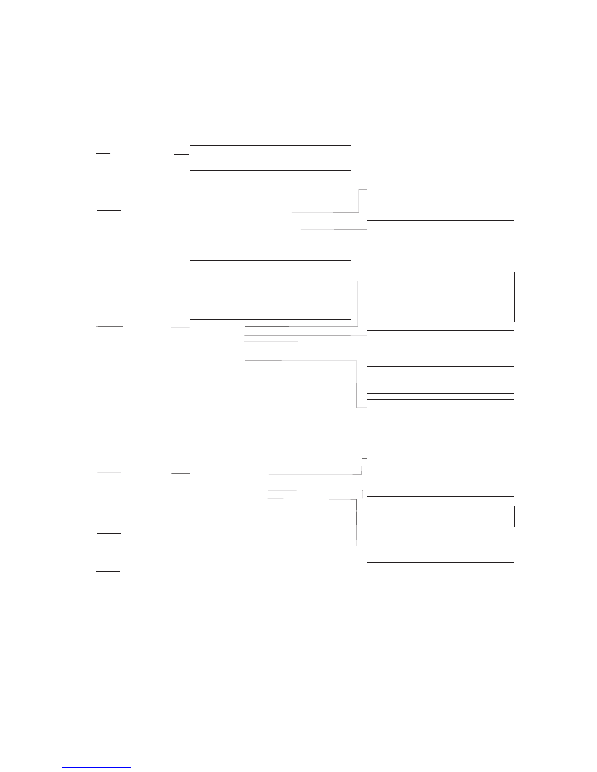
After you enter the user name and password, you will have access
to the system configuration program illustrated by the following
menu map:
Port Statistics
Layer 2 Address Table
Bridge Menu
VLAN
IP Multicast Registration Table
Menu
System
Information Menu
System Information
Switch Information
Management
Setup Menu
Network Configuration
Serial Port Configuration
SNMP Configuration
User Configuration
TFTP Download
Configuration File
Network
Monitor Menu
System
Restart Menu
Exit
SNMP Communities
IP Trap Managers
IP Configuration
IP Connectivity Test (Ping)
HTTP Configuration
VLAN Dynamic Registration Info.
VLAN Forwarding Information
Unicast Address Table
Layer 2 Menu
Bridge Menu
VLAN Menu
IGMP Snooping Configuration
Security Menu
Device
Control Menu
Port Configuration
Mirror Port Configuration
Port Trunking Configuration
Static Unicast Address Table Configuration
Static Multicast Address Table Configuration
Bridge Configuration
Port ConfigurationSpanning Tree
VLAN Port Configuration
VLAN Table Configuration
MAC Filtering Configuration
Security Mode
Port Statistics
RMON Statistics
Spanning Tree Bridge Information
Port InformationSpanning Tree

C
ONSOLE INTERFACE
2-4
Main Menu
With the system configuration program you can define system
parameters, manage and control the switch and all its ports, or
monitor network conditions. The screen below of the Main Menu
and the table following it briefly describe the selections available
from this program.
Note: Options for the currently selected item are displayed in the
highlighted area at the bottom of the interface screen.
SMC6724L2
Main Menu
=========
System Information Menu...
Management Setup Menu...
Device Control Menu...
Network Monitor Menu...
System Restart Menu...
Exit
Use <TAB> or arrow keys to move. <Enter> to select.
Menu Description
System Information Menu
System Information Provides basic system description, including
contact information.
Switch Information Shows hardware/firmware version numbers,
power status, and expansion modules used in
the switch.

M
AIN MENU
2-5
Management Setup Menu
Network Configuration Includes IP setup, Ping facility, and HTTP
(Web agent) setup.
Serial Port Configuration Sets communication parameters for the serial
port, including baud rate, console timeout,
and screen data refresh interval.
SNMP Configuration Activates authentication failure traps;
configures community access strings and trap
managers.
User Configuration Sets the user names and passwords for system
access.
TFTP Download Downloads new version of firmware to
update your system (in-band).
Configuration File Saves or restores configuration data using the
specified file.
Device Control Menu
Layer 2 Menu Configures port communication mode, mirror
ports, port trunking, and static addresses.
Bridge Menu Configures GMRP and GVRP for the bridge, as
well as Spanning Tree settings for the global
bridge or for specific ports.
VLAN Menu Configures VLAN settings for specific ports,
and defines the port membership for VLAN
groups.
IGMP Snooping
Configuration
Configures IGMP multicast filtering.
Security Menu Configures MAC address filtering, and enables
or disables address learning.
Menu Description

C
ONSOLE INTERFACE
2-6
Network Monitor Menu
Port Statistics Displays statistics on port traffic, including
information from the Interfaces Group,
Ethernet-like MIB, and RMON MIB.
Layer 2 Address Table Contains the unicast address table.
Bridge Menu Displays Spanning Tree information for the
overall bridge and for specified ports.
VLAN Menu Displays dynamic port registration
information for VLANs as well as VLAN
forwarding information for static and dynamic
assignment.
IP Multicast
Registration Table
Displays all the multicast groups active on this
switch, including the multicast IP addresses
and corresponding VLANs.
Restart System Restarts the system with options to restore
factory defaults.
Exit Exits the configuration program.
Menu Description

S
YSTEM INFORMATION MENU
2-7
System Information Menu
Use the System Information Menu to display a basic description of
the switch, including contact information, and hardware/firmware
versions.
System Information Menu
=======================
System Information ...
Switch Information ...
<OK>
Use <TAB> or arrow keys to move. <Enter> to select.
Menu Description
System Information Provides basic system description, including
contact information.
Switch Information Shows hardware/firmware version numbers,
power status, and expansion modules used in
the switch.

C
ONSOLE INTERFACE
2-8
Displaying System Information
Use the System Information screen to display descriptive
information about the switch, or for quick system identification as
shown in the following screen and table.
System Information
==================
System Description : TigerSwitch 10/100 (SMC6724L2)
System Object ID : 1.3.6.1.4.1.202.20.19
System Up Time : 1270430 (0 day 3 hr 31 min 44 sec)
System Name :
System Contact :
System Location :
<Apply> <OK> <Cancel>
Use <TAB> or arrow keys to move, other keys to make changes.
Parameter Description
System Description System hardware description.
System Object ID MIB II object identifier for switch’s network
management subsystem.
System Up Time Length of time the current management
agent has been running. (Note that the first
value is in centiseconds.)
System Name* Name assigned to the switch system.
System Contact* Contact person for the system.
System Location* Specifies the area or location where the
system resides.
*
Maximum string length is 99, but the screen only displays 45 characters.
You can use the arrow keys to browse the whole string.

S
YSTEM INFORMATION MENU
2-9
Displaying Switch Version Information
Use the Switch Information screen to display hardware/firmware
version numbers for the main board, as well as the power status.
Switch Information
==================
Hardware Version : R01
Firmware Version : V1.04
Serial Number : 00-10-B5-DD-DF-C0
Port Number : 26
Internal Power Status : Active
Fan Power Status : Active
Expansion Slot 1 : 100FX_MM
Expansion Slot 2 : 1GBase-T
<OK>
Use <Enter> to select.
Parameter Description
Hardware Version Hardware version of the main board.
Firmware Version System firmware version in ROM.
Serial Number The serial number of the main board.
Port Number Number of ports on this switch.
Internal Power Status Shows if primary power is active or inactive.
Fan Power Status Shows if power to the fan is active or inactive.
Expansion Slot 1
Expansion Slot 2
Shows module type if inserted:
100BASE-FX_MM: 100BASE-FX (multimode)
100BASE-FX_SM: 100BASE-FX (singlemode)
1GBase-SX: 1000BASE-SX (multimode)
1GBase-LX: 1000BASE-LX (singlemode)
1GBase-T: 1000BASE-T

C
ONSOLE INTERFACE
2-10
Management Setup Menu
After initially logging on to the system, adjust the communication
parameters for your console to ensure a reliable connection
(
Serial Port Configuration). Specify the IP addresses for the
switch (
Network Configuration / IP Configuration), and then set
the Administrator and User passwords (
User Configuration).
Remember to record them in a safe place. Also set the community
string which controls access to the onboard SNMP agent via
in-band management software (
SNMP Configuration). The items
provided by the Management Setup Menu are described in the
following sections.
Management Setup Menu
=====================
Network Configuration ...
Serial Port Configuration ...
SNMP Configuration ...
User Configuration ...
TFTP Download ...
Configuration File
<OK>
Use <TAB> or arrow keys to move. <Enter> to select.
Menu Description
Network Configuration Includes IP setup, Ping facility, and HTTP
setup for the onboard Web agent.
Serial Port Configuration Sets communication parameters for the serial
port, including baud rate, console timeout,
and screen data refresh interval.
SNMP Configuration Activates authentication failure traps and
configures communities and trap managers.
User Configuration Sets the user names and passwords for
system access.

M
ANAGEMENT SETUP MENU
2-11
Changing the Network Configuration
Use the Network Configuration menu to set the bootup option,
configure the switch’s Internet Protocol (IP) parameters, or enable
the onboard Web agent. The screen shown below is described in
the following table.
TFTP Download Downloads new version of firmware to
update your system (in-band).
Configuration File Saves or restores configuration data based
on the specified file.
Network Configuration
=====================
IP Configuration ...
IP Connectivity Test (Ping) ...
HTTP Configuration ...
<OK>
Use <TAB> or arrow keys to move. <Enter> to select.
Parameter Description
IP Configuration Screen used to set the bootup option, or
configure the switch’s IP parameters.
IP Connectivity Test (Ping) Screen used to test IP connectivity to a
specified device.
HTTP Configuration Screen used to enable the Web agent.
Menu Description

C
ONSOLE INTERFACE
2-12
IP Configuration
Use the IP Configuration screen to set the bootup option, or
configure the switch’s IP parameters. The screen shown below is
described in the following table.
IP Configuration
================
Interface Type : Ethernet
IP Address : 192.168.1.254
Subnet Mask : 255.255.255.0
Gateway IP : 0.0.0.0
IP State : USER-CONFIG
Mgt. Access : All VLANs
VLAN ID : 1 Mgt. Access : Mgmt VLAN
<Apply> <OK> <Cancel>
Confirm current screen setting.
Use <TAB> or arrow keys to move. <Enter> to select.
Parameter Description
Interface Type Indicates IP over Ethernet.
IP Address IP address of the switch you are managing. The system
supports SNMP over UDP/IP transport protocol. In this
environment, all systems on the Internet such as
network interconnection devices and any PC accessing
the agent module (or running EliteView) must have an
IP address.
Valid IP addresses consist of four numbers, 0 and 255,
separated by periods. Anything outside this format will
not be accepted by the configuration program.
Subnet Mask Subnet mask of the switch. This mask identifies the
host address bits used for routing to specific subnets.
Default Gateway Gateway used to pass trap messages from the system’s
agent to the management station. Note that the gateway
must be defined if the
management station is located in
a different IP segment.

M
ANAGEMENT SETUP MENU
2-13
IP State Specifies whether IP functionality is enabled via
manual configuration, or set by Boot Protocol
(BOOTP). Options include:
USER-CONFIG - IP functionality is enabled based on
the default or user specified IP
Configuration. (This is the default
setting.)
BOOTP Get IP - IP is enabled but will not function
until a BOOTP reply has been
received. BOOTP requests will be
broadcast periodically by the switch
in an effort to learn its IP address.
(BOOTP values can include the IP
address, default gateway, and subnet
mask.)
VLAN ID The VLAN used for management access when “Mgmt
VLAN” is selected. (See the next item.)
Mgt. Access Allows management access of the switch from all
VLANs or only from a specified VLAN. If you select
“Mgmt VLAN,” then select Apply to display the VLAN
ID field, select the required VLAN, and then select
Apply or OK to save your changes.
Parameter Description

C
ONSOLE INTERFACE
2-14
IP Connectivity Test (Ping)
Use the IP Connectivity Test to see if another site on the Internet
can be reached. The screen shown below is described in the
following table.
Note: The switch waits up to 10 seconds for a response to each
ping.
IP Connectivity Test (Ping)
===========================
IP Address : 10.1.3.22
Test Times : 3
Success : 3 Failure : 0
[Start] <CANCEL>
Use <TAB> or arrow keys to move, other keys to make changes.
Parameter Description
IP Address IP address of the site you want to ping.
Test Times The number of ICMP echo requests to send
to the specified site.
Range: 1~1000
Success/Failure The number of times the specified site has
responded (or not) to pinging.

M
ANAGEMENT SETUP MENU
2-15
HTTP Configuration
Use the HTTP Configuration screen to enable/disable the onboard
Web ag en t.
Note: Port 80 is used for HTTP service.
HTTP Configuration
==================
HTTP Server : ENABLED
<Apply> <OK> <Cancel>
Use <TAB> or arrow keys to move, <Space> to scroll options.

C
ONSOLE INTERFACE
2-16
Configuring the Serial Port
You can access the onboard configuration program by attaching a
VT100 compatible device to the switch’s serial port. (For more
information on connecting to this port, see “Required
Connections” on page 1-2.) The communication parameters for
this port can be accessed from the Serial Port Configuration screen
shown below and described in the following table.
Serial Port Configuration
=========================
Management Mode : CONSOLE MODE
Baud rate : 19200
Data bits : 8
Stop bits : 1
Parity : NONE
Time-Out (in minutes) : 0
Auto Refresh (in seconds) : 10
<Apply> <OK> <Cancel>
Use <TAB> or arrow keys to move, <Space> to scroll options.

M
ANAGEMENT SETUP MENU
2-17
Parameter Default Description
Management
Mode
Console
Mode
Indicates that the port settings are for direct
console connection.
Baud Rate 19200 The rate at which data is sent between
devices.
Options: 9600, 19200 and 38400 baud.
Data Bits 8 bits Sets the data bits of the RS-232 port.
Options: 7, 8
Stop Bits 1 bit Sets the stop bits of the RS-232 port.
Options: 1, 2
Parity None Sets the parity of the RS-232 port.
Options: none, odd, even
Timeout 10 minutes If no input is received from the attached
device after this interval, the current session
is automatically closed.
Range : 0 - 100 minutes; 0 indicates disabled
Auto Refresh 1 second Sets the interval before a console session
will auto-refresh the console information,
such as Spanning Tree Information, Port
Configuration, Port Statistics, and RMON
Statistics.
Range : 0-255 seconds; 0 indicates disabled

C
ONSOLE INTERFACE
2-18
Assigning SNMP Parameters
Use the SNMP Configuration screen to display and modify
parameters for the Simple Network Management Protocol (SNMP).
The switch includes an onboard SNMP agent which monitors the
status of its hardware, as well as the traffic passing through its
ports. A computer attached to the network, called a Network
Management Station (NMS), can be used to access this
information. Access rights to the onboard agent are controlled by
community strings. To communicate with the switch, the NMS
must first submit a valid community string for authentication. The
options for configuring community strings and related trap
functions are described in the following sections.
SNMP Configuration
==================
Send Authentication Fail Traps : ENABLED
SNMP Communities ...
IP Trap Managers ...
<OK>
Use <TAB> or arrow keys to move, <Space> to scroll options.
Parameter Description
Send Authentication
Fail Traps
Issue a trap message to specified IP trap managers
whenever authentication of an SNMP request
fails. (The default is enabled.)
SNMP Communities Assigns SNMP access based on specified strings.
IP Trap Managers Specifies management stations that will receive
authentication failure messages or other trap
messages from the switch.

M
ANAGEMENT SETUP MENU
2-19
Configuring Community Names
The following figure and table describe how to configure the
community strings authorized for management access. Up to 5
community names may be entered.
Note: The default community strings are displayed on the screen.
SNMP Communities
================
Community Name Access Status
1. public READ/WRITE ENABLED
2. private READ ONLY ENABLED
3.
4.
5.
<APPLY> <OK> <CANCEL>
Use <TAB> or arrow keys to move, other keys to make changes.
Parameter Description
Community Name A community entry authorized for management
access.
Maximum string length: 19 characters
Access Management access is restricted to Read Only or
Read/Write.
Status Sets administrative status of entry to enabled or
disabled.

C
ONSOLE INTERFACE
2-20
Configuring IP Trap Managers
The following figure and table describe how to specify
management stations that will receive authentication failure
messages or other trap messages from the switch. Up to 5 trap
managers may be entered.
IP Trap Managers
================
IP Address Community Name Status
1. 10.1.0.23 public ENABLED
2.
3.
4.
5.
<APPLY> <OK> <CANCEL>
Use <TAB> or arrow keys to move, other keys to make changes.
Parameter Description
IP Address IP address of the trap manager.
Community Name A community specified for trap management
access.
Status Sets administrative status of selected entry to
enabled or disabled.

M
ANAGEMENT SETUP MENU
2-21
User Log-in Configuration
Use the User Configuration menu to restrict
management access
based on specified user names and passwords.
There are two user
types, Administrator and Guest. Only the Administrator has write
access for parameters governing the SNMP agent. You should
therefore assign a user name and password to the Administrator as
soon as possible, and store it in a safe place. (If for some reason
your password is lost, or you cannot gain access to the System
Configuration Program, enter “ResetSystem” for the user name,
with no password.) The parameters shown on this screen are
indicated in the following figure and table.
User Configuration
==================
User Name Access Right Console Telnet HTTP
guest GUEST DISABLED DISABLED ENABLED
admin ADMIN ENABLED ENABLED ENABLED
<Add> <OK>
Use <TAB> or arrow keys to move. <Enter> to select.
Parameter Description
User Name Specifies a user authorized management access to the
switch via the console, Telnet or HTTP.
Access Right ADMIN: Read/Write for all screens.
GUEST: Read Only for all screens.
Console Authorizes management via the console.
Telnet Authorizes management via Telnet.
HTTP Authorizes management via HTTP (i.e., a Web browser).

C
ONSOLE INTERFACE
2-22
To add a new user, select <Add>. When you add a user, the
following screen is displayed.
Add User
========
User Name :
Password :
Access Right GUEST
Console Access DISABLED
Telnet Access DISABLED
HTTP Access ENABLED
<OK> <Cancel>
Use <TAB> or arrow keys to move, other keys to make changes.
Parameter Description
User Name* Specifies a user authorized management access to the
switch via the console, Telnet or HTTP.
Password* Password associated with this entry.
Access Right ADMIN: Read/Write for all screens.
GUEST: Read Only for all screens.
Console Access Authorizes management via the console.
Telnet Access Authorizes management via Telnet.
HTTP Access Authorizes management via HTTP (i.e., a Web browser).
* These entries can consist of up to 15 alphanumeric characters and are not
case sensitive.

M
ANAGEMENT SETUP MENU
2-23
Downloading System Software
Use the TFTP Download menu to load software updates to
permanent flash ROM in the switch. The download file should be
an SMC6724L2 binary file from SMC; otherwise the agent will not
accept it. The success of the download operation depends on the
accessibility of the TFTP server and the quality of the network
connection. After downloading the new software, the agent will
automatically restart itself. Parameters shown on this screen are
indicated in the following figure and table.
Note: You can also download firmware using the Web agent
(page 3-18) or by a direct console connection after a restart
(page A-2).
TFTP Download
=============
Download Server IP : 190.186.144.20
Download Filename :
Download Option : Runtime Code
<APPLY> <OK> <CANCEL>
Use <TAB> or arrow keys to move, other keys to make changes.
Parameter Description
Download Server IP IP address of a TFTP server.
Download Filename The binary file to download.
Download Option Select to download “Post Code” or “Runtime
Code.”

C
ONSOLE INTERFACE
2-24
Saving or Restoring the System Configuration
Use the Configuration File menu to save the switch configuration
settings to a file on a TFTP client. The file can be later downloaded
to the switch to restore the switch’s settings. The success of the
operation depends on the accessibility of the TFTP client and the
quality of the network connection. Parameters shown on this
screen are indicated in the following figure and table.
To transfer a file –
Switch: Specify the IP address of the TFTP client, and select
“Download from switch” or “Upload from Switch.”
TFTP Client: Set the mode to <binary>, specify the IP address of
the target switch and the directory path / name of the file to transfer.
Configuration File
======================
Station IP :190.186.144.20
Operation :Download from switch
<START> <Cancel>
Use <TAB> or arrow keys to move, other keys to make changes.
Parameter Description
Station IP IP address of a PC running TFTP client software.
Operation Download from switch – Downloads the current switch
configuration to a file on the client PC.
Upload to switch – Uploads a configuration file to the
switch from the client PC.

M
ANAGEMENT SETUP MENU
2-25
Switch: Select <START> from the Configuration File menu.
TFTP Client: Start transferring the configuration file from the TFTP
client or the switch, and wait until the transfer completes.
Saving and restoring switch configuration settings can be initiated
by using any TFTP client utility, such as the command line utility
included in Windows NT. For example, using Windows NT, from a
DOS window command prompt, enter the TFTP command in the
form:
TFTP -i host [GET : PUT] source [destination]
For example: TFTP -i 190.186.144.20 GET abc c:\6724L2.cfg
will download the current configuration of the switch with IP
address 190.186.144.20 to the file “6724L2.cfg,” in drive “c:\,” of
the TFTP client PC.
Parameter Description
-i Specifies that binary mode is used for the transfer. If
binary mode is not specified, the default will be ASCII.
Always specify binary mode to save or restore
configuration settings.
host The IP address of the switch.
Get Downloads the current switch configuration to the TFTP
client.
PUT Uploads a specified configuration file from the TFTP
client to the switch.
source* Specifies the file to transfer.
destination* Specifies where to transfer the file
When downloading the current configuration settings “source” has no
meaning. When uploading a configuration from a file on the TFTP client
“destination” has no meaning. However, these parameters must still be
specified for the transfer to work. Any name (eg., abc) may be used for
these parameters, provided it is of no more than 8 characters.

C
ONSOLE INTERFACE
2-26
Device Control Menu
The Device Control menu is used to control a broad range of
functions, including port mode, port mirroring, port trunking,
Spanning Tree, Virtual LANs, IP subnets, multicast filtering, and
routing protocols. Each of the setup screens provided by these
configuration menus is described in the following sections.
Device Control Menu
===================
Layer 2 Menu ...
Bridge Menu ...
VLAN Menu ...
IGMP Snooping Configuration ...
Security Menu ...
<OK>
Use <TAB> or arrow keys to move. <Enter> to select.
Menu Description
Layer 2 Menu Configures port communication mode, mirror ports,
and port trunking.
Bridge Menu Configures the Spanning Tree Protocol for the bridge
or for specific ports, GMRP and GVRP for automatic
registration of multicast and VLAN groups, traffic class
priority threshold, and address aging time.
VLAN Menu Configures VLAN settings for specific ports, and
defines the port membership for VLAN groups.
IGMP Snooping
Configuration
Configures IGMP multicast filtering.
Security Menu Configures MAC address filtering, and enables or
disables address learning.

D
EVICE CONTROL MENU
2-27
Layer 2 Menu
The Layer 2 menu contains options for port configuration, port
mirroring, port trunking, static unicast address configuration and
static multicast address configuration. These menu options are
described in the following sections.
Layer 2 Menu
============
Port Configuration ...
Mirror Port Configuration ...
Port Trunking Configuration ...
Static Unicast Address Configuration ...
Static Multicast Address Configuration ...
<OK>
Use <TAB> or arrow keys to move. <Enter> to select.
Menu Description
Port
Configuration
Enables any port, enables/disables flow control, and
sets communication mode to auto-negotiation, full
duplex or half duplex.
Mirror Port
Configuration
Sets the source and target ports for mirroring.
Port Trunking
Configuration
Specifies ports to group into aggregate trunks.
Static Unicast
Address Table
Used to manually configure host MAC addresses in
the unicast table.
Static Multicast
Address Table
Used to manually configure host MAC addresses in
the multicast table.

C
ONSOLE INTERFACE
2-28
Configuring Port Parameters
Use the Port Configuration menu to display or set communication
parameters for any port or module on the switch, including
administrative status, auto-negotiation, default communication
speed and duplex mode, as well as flow control in use.
Layer 2 Menu: Port Configuration (Port 1-12)
============
Port Link Admin Auto Default Current Flow Jack
Status Status Negotiate Type Type Control Type
------------------------------------------------------------------1 On ENABLED ENABLED 10HDX 100TX-FDX Off RJ-45
2 Off ENABLED ENABLED 10HDX 10HDX Off RJ-45
3 Off ENABLED ENABLED 10HDX 10HDX Off RJ-45
4 Off ENABLED ENABLED 10HDX 10HDX Off RJ-45
5 Off ENABLED ENABLED 10HDX 10HDX Off RJ-45
6 Off ENABLED ENABLED 10HDX 10HDX Off RJ-45
7 Off ENABLED ENABLED 10HDX 10HDX Off RJ-45
8 Off ENABLED ENABLED 10HDX 10HDX Off RJ-45
9 Off ENABLED ENABLED 10HDX 10HDX Off RJ-45
10 Off ENABLED ENABLED 10HDX 10HDX Off RJ-45
11 Off ENABLED ENABLED 10HDX 10HDX Off RJ-45
12 Off ENABLED ENABLED 10HDX 10HDX Off RJ-45
<Apply> <OK> <Cancel> <Prev Page> <Next Page>
Use <TAB> or arrow keys to move, <Space> to scroll options.

D
EVICE CONTROL MENU
2-29
Parameter Default Description
Link Status Indicates if the port has a valid connection to
an external device.
Admin
Status
Enabled Allows you to disable a port due to abnormal
behavior (e.g., excessive collisions), and
then reenable it after the problem has been
resolved. You may also disable a port for
security reasons.
Auto
Negotiate
Enabled Enables or disables auto-negotiation for the
following features
Port Type Speed Duplex Flow
Mode Control
10/100BASE-T auto auto auto
100BASE-FX 100M full duplex auto
1000BASE-SX 1000M full duplex auto
1000BASE-LX 1000M full duplex auto
1000BASE-T 1000M full duplex auto
The 10/100BASE-TX ports can
auto-negotiate the speed to 10/100
Mbps,
and the transmission mode to half/full duplex.
The plug-in
modules are all fixed at the
indicated speed and duplex mode. All media
types can auto-negotiate flow control.
Default Type 10HDX If auto-negotiation is disabled, the port will
be set to the indicated speed and duplex
mode.
Current Type Indicates the current speed and duplex
mode.

C
ONSOLE INTERFACE
2-30
Flow Control Off Used to enable or disable flow control. Flow
control can eliminate frame loss by
“blocking” traffic from end stations or
segments connected directly to the switch
when its buffers fill. When enabled, back
pressure is used for half duplex and IEEE
802.3x for full duplex. Note that flow control
should not be used if a port is connected to
a hub. For the Gigabit modules the options
for flow control are set out below:
Switch Link Partner* Flow Control
SendOnly Rcv/BothWay Switch can only
send pause
frames, link
partner can only
receive pause
frames.
BothWay Rcv/BothWay Both switch and
link partner can
send and receive
pause frames.
* SMC6724L2 or SMC6724L3
Jack Type Shows the jack type for each port.
Ports 1-24: RJ-45
Ports 25-26: SC, RJ-45
Parameter Default Description

D
EVICE CONTROL MENU
2-31
Using a Mirror Port for Analysis
You can mirror traffic from any source port to a target port for
real-time analysis. You can then attach a logic analyzer or RMON
probe to the target port and study the traffic crossing the source
port in a completely unobtrusive manner. When mirroring port
traffic, note that the target port must be included in the same VLAN
as the source port. (See “Configuring Virtual LANs” on page 2-43.)
You can use the Port Mirror Configuration screen to mirror one or
more ports to the monitor port as shown below.
Note: You can mirror multiple ports to a single port to view traffic
such as that crossing a port trunk. However, note that some
packets may be dropped for moderate to heavy loading.
Layer 2 Menu: Mirror Port Configuration
============
Enable Port Mirror: ENABLED
Transmission Path
Mirrored Ports
Tx: 4
Rx: 5
Monitor Port Tx : 2
Monitor Port Rx : 3
<Apply> <OK> <Add>
Use <TAB> or arrow keys to move, <Space> to scroll options.
Parameter Description
Enable Port Mirror Enables or disables the mirror function.
Mirrored Ports (Tx/Rx) The port whose transmitted or received traffic will
be mirrored. Select <Add> to specify mirrored
ports.
Monitor Port The port that will duplicate the transmitted or
received traffic appearing on the mirrored port.

C
ONSOLE INTERFACE
2-32
Configuring Port Trunks
Ports can be combined into an aggregate link to increase the
bandwidth of a network connection or to ensure fault recovery.
You can configure trunks between any two SMC6724L2 or
SMC6724L3 switches. Ports 1-24 on this switch can be grouped
into a trunk consisting of two, four or eight ports, creating an
aggregate bandwidth up to 400, 800 or 1600 Mbps when operating
at full duplex. Ports 25-26 (extender module ports) can be trunked
together creating an aggregate bandwidth up to 2 Gbps (see page
2-34). The ports that can be assigned to the same trunk are listed
on page 2-33. Besides balancing the load across each port in the
trunk, the additional ports provide redundancy by taking over the
load if another port in the trunk fails. However, before making any
physical connections between devices, use the Port Trunking
Configuration menu to specify the trunk on the devices at both
ends. When using a port trunk, remember that:
• Ports can only be assigned to one trunk.
• The ports at both ends of a connection must be configured as
trunk ports.
• The ports at both ends of a trunk must be configured in an
identical manner, including communication mode, and VLAN
assignments.
• All the ports in a trunk have to be treated as a whole when
moved from/to, added or deleted from a VLAN.
• The Spanning Tree Algorithm will treat all the ports in a trunk
as a whole.
• Enable the trunk prior to connecting any cable between the
switches to avoid creating a loop.

D
EVICE CONTROL MENU
2-33
You can use the Port Trunking Configuration screen to set up port
trunks as shown below:
The port groups permitted include:
Layer 2 Menu: Port Trunking Configuration
============
Index Port Count Port Number
Trunk1 2 14 02
Trunk2 4 15 03 16 04
Trunk3 8 1705180619072008
<OK> <Add>
Use <TAB> or arrow keys to move. <Enter> to select.
Parameter Description
Index The trunk identifier.
Port Count Trunks can contain 2, 4 or 8 ports.
Port Number The ports assigned to each trunk.
<<13, 1>> <<14, 2>> <<15, 3>> <<16, 4>>
<<17, 5>> <<18, 6>> <<19, 7>> <<20, 8>>
<<21, 9>> <<22,10>> <<23,11>> <<24,12>>
<<13, 1, 14, 2>> <<15, 3, 16, 4>>
<<17, 5, 18, 6>> <<19, 7, 20, 8>>
<<21, 9, 22, 10>> <<23, 11, 24, 12>>
<<13, 1, 14, 2, 15, 3, 16, 4>>
<<17, 5, 18, 6, 19, 7, 20, 8>>
<<21, 9, 22, 10, 23, 11, 24, 12>>
<<25, 26>>

C
ONSOLE INTERFACE
2-34
For the extender modules (ports 25, 26), the possible port trunking
combinations are set out belo
w.
To add a trunk, select <Add>. To delete a trunk, highlight the
required entry and select Enter. Before disconnecting a port trunk,
take the following steps:
• Before removing a port trunk via the configuration menu, you
must disable all the ports in the trunk or remove all the network
cables. Otherwise, a loop may be created.
• To disable a single link within a port trunk, you should first
remove the network cable, and then disable both ends of the
link via the configuration menu. This allows the traffic passing
across that link to be automatically distributed to the other links
in the trunk, without losing any significant amount of traffic.
Extender Module
100BASE-FX Can be trunked together.
1000BASE-SX,
1000BASE-LX,
1000BASE-T
Can be trunked together, irrespective of media.

D
EVICE CONTROL MENU
2-35
Configuring the Static Unicast Address Table
The Static Unicast Address Table can be used to assign the MAC
address for a host device to a specific port on this switch. Static
unicast addresses are never aged out, and cannot be learned on
another port. If any packets with a source address specified in this
table enter another port, they will be dropped. The Static Unicast
Address Table is described in the following figure and table.
Notes: 1. To assign a MAC address to a specific port, use <Add>.
To delete or modify an address, highlight it with the
cursor and select Enter.
2. To scroll through the address table, use the <Next Page>
and <Prev Page> buttons.
3. To display a specific page, set the page number in the
Page field and then select <Apply>.
Layer 2 Address Table: Static Address Table
=====================
Address Port Address Port
30-30-30-30-30-30 1
Page 1 <Apply> Total 1 Pages
<OK> <Next Page> <Prev Page> <Add>
Use <TAB> or arrow keys to move. <Enter> to select.
Parameter Description
Address The MAC address of a host device attached to this switch.
Port The switch port to which the host device is attached.

C
ONSOLE INTERFACE
2-36
Configuring the Static Multicast Address Table
The Static Multicast Address Table can be used to assign a
destination MAC address (and the corresponding ports) to the
VLAN group used for a specific multicast service. Static multicast
addresses are never
aged out, and traffic with these addresses can
be forwarded only to ports specified in this table
.
Notes: 1. To assign a destination MAC address to one or more
ports, use <Add>. To delete or modify an address,
highlight it with the cursor and select Enter.
2. To scroll through the address table, use the <Next Page>
and <Prev Page> buttons.
3. To display a specific page, set the page number in the
Page field and then select <Apply>.
Layer 2 Menu: Multicast Address Table
============
Port 1 2
VLAN Address 12345678901234567890123456
1 61-60-60-60-60-60 M
Page 1 <Apply> Total 1 Pages
<OK> <Next Page> <Prev Page> <Add>
Use <TAB> or arrow keys to move. <Enter> to select.
Parameter Description
VLAN The VLAN corresponding to this multicast service.
Address The destination MAC address for a multicast service.
Port The ports to which this multicast traffic can be forwarded.

D
EVICE CONTROL MENU
2-37
Using the Bridge Menu
The Bridge menu is used to configure settings for the Spanning
Tree Algorithm, as well as the global bridge settings for GMRP
(GARP Multicast Registration Protocol) and GVRP (GARP VLAN
Registration Protocol), traffic class priority threshold, and address
aging time.
The Spanning Tree Algorithm can be used to detect and disable
network loops, and to provide backup links between switches,
bridges or routers. This allows the switch to interact with other
bridging devices (that is, an STA-compliant switch, bridge or
router) in your network to ensure that only one route exists
between any two stations on the network, and provide backup
links which automatically take over when a primary link goes
down. For a more detailed description of how to use this
algorithm, refer to “Spanning Tree Algorithm” on page 4-4.
Bridge Menu
============
Bridge Configuration ...
Spanning Tree Port Configuration ...
<OK>
Use <TAB> or arrow keys to move. <Enter> to select.
Menu Description
Bridge
Configuration
Contains global bridge settings for STA (including
bridge priority, hello time, forward delay, maximum
message age), GMRP, GVRP, traffic class priority
threshold, and address aging time.
Spanning Tree
Port Configuration
Contains STA settings for individual ports, including
port priority, path cost, and fast forwarding.

C
ONSOLE INTERFACE
2-38
Configuring Global Bridge Settings
The following figure and table describe bridge configuration for
STA, GMRP, GVRP, priority threshold, and address aging time.
Bridge Configuration
====================
Spanning Tree :ENABLED GMRP :DISABLED
Bridge Priority :32768 GVRP :DISABLED
Hello Time (in seconds) :2 Priority Threshold :4
Forward Delay (in seconds) :15 Aging Time (in seconds):300
Max age (in seconds) :20
<Apply> <OK> <Cancel>
Use <TAB> or arrow keys to move, <Space> to scroll options.
Parameter Default Description
Spanning Tree Enabled Enable this parameter to participate in a STA
compliant network.
Bridge Priority 32,768 Bridge priority is used in selecting the root
device, root port, and designated port. The
device with the highest priority becomes the
STA root device. However, if all devices have
the same priority, the device with the lowest
MAC address will then become the root device.
Enter a value from 0 - 65535.
Remember that the lower the numeric value, the
higher the priority.
Hello Time 2 Time interval (in seconds) at which the root
device transmits a configuration message.
The minimum value is 1.
The maximum value is the lower of 10 or
[(Max. Message Age / 2) -1].

D
EVICE CONTROL MENU
2-39
Forward Delay 1 The maximum time (in seconds) the root device
will wait before changing states (i.e., listening to
learning to forwarding). This delay is required
because every device must receive information
about topology changes before it starts to
forward frames. In addition, each port needs
time to listen for conflicting information that
would make it return to a blocking state;
otherwise, temporary data loops might result.
The maximum value is 30.
The minimum value is the higher of 4 or
[(Max. Message Age / 2) + 1].
Max
(Message) Age
20 The maximum time (in seconds) a device can
wait without receiving a configuration message
before attempting to reconfigure. All device
ports (except for designated ports) should
receive configuration messages at regular
intervals. Any port that ages out STA information
(provided in the last configuration message)
becomes the designated port for the attached
LAN. If it is a root port, a new root port is
selected from among the device ports attached
to the network.
The minimum value is the higher of 6 or
[2 x (Hello Time + 1)].
The maximum value is the lower of 40 or
[2 x (Forward Delay - 1)].
GMRP Disabled GARP Multicast Registration Protocol (GMRP)
allows network devices to register endstations
with multicast groups.
If GMRP is globally enabled for the switch, then
you can individually enable or disable GMRP for
a specific port. See “VLAN Port Configuration”
on page 2-43.
IGMP and IGMP Snooping also provide
multicast filtering. (See “IGMP Protocol” on page
4-10.)
Parameter Default Description

C
ONSOLE INTERFACE
2-40
GVRP Disabled GARP VLAN Registration Protocol (GVRP)
defines a way for switches to exchange VLAN
information in order to register VLAN members
on ports across the network. This function
should be enabled to permit automatic VLAN
registration, and to support
VLANs which extend
beyond the local switch.
If GVRP is globally enabled for the switch, then
you can individually enable or disable GVRP for
a specific port. See “VLAN Port Configuration”
on page 2-43.
Priority
Threshold*
4 This switch supports Quality of Service (QoS) by
using two priority queues, with Weighted Fair
Queuing for each port. Up to 8 separate traffic
classes are defined in IEEE 802.1p. Therefore,
any packets with a priority equal to or higher
than this threshold are placed in the high
priority queue.
(Address)
Aging Time
300 Timeout period in seconds for aging out
dynamically learned forwarding information.
Range: 10 - 415 seconds
* You can use “VLAN Port Configuration” on page 2-43 to configure the
default priority for each port.
Parameter Default Description

D
EVICE CONTROL MENU
2-41
Configuring STA for Ports
The following figure and table describe port STA configuration.
Spanning Tree Port Configuration (Port 1-12)
================================
Port Type Priority Cost FastForwarding
------------------------------------------------------1 100TX 128 19 DISABLED
2 100TX 128 19 DISABLED
3 100TX 128 19 DISABLED
4 100TX 128 19 DISABLED
5 100TX 128 19 DISABLED
6 100TX 128 19 DISABLED
7 100TX 128 19 DISABLED
8 100TX 128 19 DISABLED
9 100TX 128 19 DISABLED
10 100TX 128 19 DISABLED
11 100TX 128 19 DISABLED
12 100TX 128 19 DISABLED
<Apply> <OK> <Cancel> <Prev Page> <Next Page>
Use <TAB> or arrow keys to move. <Enter> to select.
Parameter Default Description
Type Shows port type as:
100TX 10BASE-T / 100BASE-TX
100BASE-FX_MM: 100BASE-FX (multimode)
100BASE-FX_SM: 100BASE-FX (singlemode)
1GBase-SX: 1000BASE-SX (multimode)
1GBase-LX: 1000BASE-LX (singlemode)
1GBase-T: 1000BASE-T
Priority 128 Defines the priority for the use of a port in the
STA algorithm. If the path cost for all ports on a
switch are the same, the port with the highest
priority (that is, lowest value) will be configured
as an active link in the Spanning Tree. Where
more than one port is assigned the highest
priority, the port with lowest numeric identifier
will be enabled. The range is 0 - 255.

C
ONSOLE INTERFACE
2-42
(Path) Cost 100/19/4 This parameter is used by the STA algorithm to
determine the best path between devices.
Therefore, lower values should be assigned to
ports attached to faster media, and higher
values assigned to ports with slower media.
(Path cost takes precedence over port priority.)
The default and recommended range is:
Ethernet: 100 (50~600)
Fast Ethernet: 19 (10~60)
Gigabit Ethernet: 4 (3~10)
The full range is 0 - 65535.
Fast
Forwarding*
Disabled This parameter is used to enable/disabled the
Fast Spanning Tree mode for the selected port.
In this mode, ports skip the Blocked, Listening
and Learning states and proceed straight to
Forwarding.
* Since end-nodes cannot cause forwarding loops, they can be passed
through the Spanning Tree state changes more quickly than allowed by
standard convergence time. Fast Forwarding can achieve quicker
convergence for end-node workstations and servers, and also overcome
other STA related timeout problems. (Remember that Fast Forwarding
should only be enabled for ports connected to an end-node device.)
Parameter Default Description

D
EVICE CONTROL MENU
2-43
Configuring Virtual LANs
You can use the VLAN configuration menu to assign any port on
the switch to any of up to 256 Virtual LAN groups. In conventional
networks with routers, broadcast traffic is split up into separate
domains. Switches do not inherently support broadcast domains.
This can lead to broadcast storms in large networks that handle
traffic such as IPX or NetBeui. By using IEEE 802.1Q-compliant
VLANs, you can organize any group of network nodes into
separate broadcast domains, thus confining broadcast traffic to the
originating group. This also provides a more secure and cleaner
network environment. For more information on how to use
VLANs, see “Virtual LANs” on page 4-5. The VLAN configuration
screens are described in the following sections.
VLAN Port Configuration
You can use the VLAN Port Configuration screen to configure GARP,
the default VLAN identifier, default port priority, VLAN tagging on
outgoing frames, GVRP and GMRP status, and filtering of incoming
frames for VLAN groups to which this port does not belong.
VLAN Menu: VLAN Port Configuration
=========
GARP Configuration
Join Time 20 Centiseconds
Leave Time 60 Centiseconds
Leave All Time 1000 Centiseconds
VLAN and Priority
Port VID 1
Port Default Priority 0
VLAN Tagging Rx All, Tx All
GVRP ENABLED
GMRP ENABLED
Ingress Filtering DISABLED
Port 1 <Apply> <OK> <Cancel> <Prev Port> <Next Port>
Use <TAB> or arrow keys to move, other keys to make changes.

C
ONSOLE INTERFACE
2-44
Parameter Default Description
GARP
1
Group Address Registration Protocol is used by
GVRP and GMRP to register or deregister client
attributes for client services within a bridged LAN.
Join Time 20 The interval (centiseconds) between
transmitting requests/queries to participate in a
group.
Leave Time 60 The interval (centiseconds) a port waits before
leaving a group.
This time should be set to more than twice the
Join Time. This ensures that after a Leave or
LeaveAll message has been issued, the
applicants can re-join before the port actually
leaves the group.
Leave All
Time
1000 The interval (centiseconds) between sending
out a LeaveAll query message for group
participants and the port leaving the group.
This interval should be considerably larger than
the Leave Time to minimize the amount of
traffic generated by nodes rejoining the group.
1. The default values for the GARP timers are independent of the media
access method or data rate. These values should not be changed unless
you are experiencing difficulties with GMRP or GVRP registration/
deregistration.

D
EVICE CONTROL MENU
2-45
VLAN and Priority These fields set the default values for VLANs,
port priority, GVRP and GMRP.
Port VID 1 The VLAN ID assigned to untagged frames
received on this port.
Port Default
Priority
2
0 Set the default ingress priority to any value
beneath the priority threshold (page 2-40) to
specify the low priority queue, or to any value
equal to or above this threshold to specify the
high priority queue.
VLAN
Tagging
3
Rx All,
Tx All
Indicates whether or not VLAN tags will be
included on frames passing through this port.
The options include:
Rx All: Accepts all frames, tagged or
untagged.
Rx Tag: Only accepts tagged frames. The
switch will only accept frames if the
PVID and frame tag are the same.
Tx All: If the PVID and frame tag are the
same, sends a tagged frame, otherwise
sends an untagged frame.
Tx Untag: Sends only untagged frames.
2. This switch supports Quality of Service (QoS) by using two priority
queues, with Weighted Fair Queuing for each port. Inbound frames that
do not have VLAN tags are tagged with the input port’s default ingress
user priority, and then placed in the appropriate priority queue at the
output port. The default priority for all ingress ports is zero. Therefore,
any inbound frames that do not have priority tags will be placed in the
low priority queue of the output port. (Note that if the output port is an
untagged member of the associated VLAN, these frames are stripped of
all VLAN tags prior to transmission.)
3. If you want to create a small port-based VLAN for just one or two
switches, you can assign ports to the same untagged VLAN (and use a
separate connection where a VLAN crosses the switches). However, to
participate in a VLAN group that extends beyond this switch, we
recommend using the VLAN ID for that group, by VLAN tagging. For
Layer 2 switching, ports assigned to a large VLAN group that crosses
several switches must use VLAN tagging.
Parameter Default Description

C
ONSOLE INTERFACE
2-46
GVRP Enabled Enables or disables GVRP for this port. When
disabled, any GVRP packets received on this
port will be discarded and no GVRP
registrations will be propagated from other
ports.
Note that GVRP must be enabled globally for
the switch before this setting can take effect.
(See “Configuring Global Bridge Settings” on
page 2-38.)
GMRP Enabled Enables or disables GMRP for this port. When
enabled, this port will allow endstations to
register with multicast groups using GMRP.
Note that GMRP must be enabled for the switch
before this setting can take effect (page 2-38).
IGMP and IGMP Snooping also provide
multicast filtering. (See “IGMP Protocol” on
page 4-10.)
Ingress
Filtering
4
Disabled If enabled, incoming frames for VLANs which
do not include this ingress port in their member
set will be discarded at the ingress port.
4. This control does not affect VLAN independent BPDU frames, such as
GVRP or STP. However, they do affect VLAN dependent BPDU frames,
such as GMRP.
Parameter Default Description

D
EVICE CONTROL MENU
2-47
VLAN Table Configuration
Use this screen to create a new VLAN or modify the settings for an
existing VLAN.
Notes: 1. Use the <Next Page> and <Prev Page> buttons to scroll
through the table.
2. To display a specific page, set the page number in the
Page field and select <Apply>.
3. To modify a VLAN group, highlight the entry in the
table
and select Enter. To add a VLAN group, select <Add>.
VLAN Menu: VLAN Table Configuration
=========
Port 1 2
VLAN 12345678901234567890123456
1 SSSSSSSSSSSSSSSSSSSSSSSSSS -: Normal
S: Static
R: Reg. Fixed
X: Forbidden
Page : 1 <Apply> Total: 1 Pages
<OK> <Prev Page> <Next Page> <Add>
Use <TAB> or arrow keys to move, other keys to make changes.
Parameter Description
VLAN The ID for the VLAN currently displayed.
Range: 1-4094
Port Port entries may be marked as:
-:(Normal) Uses GVRP to determine port membership.
S:(Static) Adds port as a static entry. GVRP protocol is
disabled.
R:(Registration Fixed) Adds port as a static entry. GVRP
protocol messages are still forwarded through this port.
X: (Forbidden) Disables GVRP for this VLAN on the specified
port.
If a removed port is no longer assigned to any other group as
an untagged port, it will automatically be assigned to VLAN
group 1 as untagged.

C
ONSOLE INTERFACE
2-48
Configuring IGMP Snooping
Multicasting is used to support real-time applications such as video
conferencing or streaming audio. A multicast server does not have
to establish a separate connection with each client. It merely
broadcasts its service to the network, and any hosts which want to
receive the multicast register with their local multicast switch/
router. Although this approach reduces the network overhead
required by a multicast server, the broadcast traffic must be
carefully filtered at every multicast switch/router it passes through
to ensure that traffic is only passed on to the hosts which
subscribed to this service.
This switch uses IGMP (Internet Group Management Protocol)
Snooping to monitor any attached hosts which want to receive a
specific multicast service. It looks up the IP Multicast Group used
for this service, and adds to it any port that received a similar
request.

D
EVICE CONTROL MENU
2-49
You can use the IGMP Snooping Configuration screen to configure
multicast filtering as shown below.
IGMP Snooping Configuration
===========================
IGMP Snooping Status : DISABLED
IGMP Router Timeout (Minutes) : 5
IGMP Group Timeout (Minutes) : 5
Act as IGMP Querier : DISABLED
<Apply> <OK> <Cancel>
Use <TAB> or arrow keys to move, <Space> to scroll options.
Parameter Default Description
IGMP
Snooping
Status
Disabled If enabled, the switch will monitor network
traffic to determine which hosts want to
receive multicast traffic. This is also referred to
as IGMP Snooping.
IGMP Router
Timeout
5 A switch port that stops receiving multicast
protocol packets for this interval will be
removed from the IGMP forwarding list.
Range: 3 - 5 minutes
IGMP Group
Timeout
5 The time between last spotting an IGMP
Report message for an IP multicast address on
a specific port and the switch removing that
entry from its list.
Range: 3 - 5 minutes
Act as IGMP
Querier
Disabled If enabled, the switch can serve as the
“querier,” which is responsible for asking hosts
if they want to receive multicast traffic.

C
ONSOLE INTERFACE
2-50
Configuring Security Filters
You can use the Security menu to filter MAC addresses or to
enable/disable address learning.
Security Menu
=============
MAC Filtering Configuration ...
Security Mode ...
<OK>
Use <TAB> or arrow keys to move. <Enter> to select.
Parameter Description
MAC Filtering
Configuration
Specifies the source or destination MAC address
for any traffic to be filtered from the switch.
Security Mode Enables or disables address learning.

D
EVICE CONTROL MENU
2-51
Configuring MAC Address Filters
Any node that presents a security risk or is functioning improperly
can be filtered from this switch. You can drop all the traffic from a
host device based on a specified MAC address. Traffic with either a
source or destination address listed in the Security Filtering
Configuration table will be filtered.
Notes: 1. To add a MAC address to the security filter, use <Add>.
To delete an address, highlight it with the cursor and
select Enter.
2. To scroll through the address table, use the <Next Page>
and <Prev Page> buttons.
3. To display a specific page, set the page number in the
Page field and then select <Apply>.
MAC Security Filtering Configuration
====================================
----------------------------------------------------------------------00-00-00-87-33-AF
Page 1 <Apply> Total 1 Pages
<OK> <Prev Page> <Next Page> <Add>
Use <TAB> or arrow keys to move. <Enter> to select.

C
ONSOLE INTERFACE
2-52
Security Mode
The learning function enables ports to learn the <source MAC
address, VLAN> pair of received frames. This information is then
used to make later decisions for frame forwarding. The learning
function should be initially enabled for a long enough period to
ensure that all valid VLAN members have been registered on the
switch. It may then be disabled as a security feature to ensure that
frames from any station with an unknown MAC address are
filtered.
To add new VLAN members at a later time, the learning
function must be re-enabled until all the new VLAN members have
been registered. Learning may then be disabled again, if desired,
for security.
Security Menu: Security Mode
=============
Learning Function : ENABLED
<Apply> <OK> <Cancel>
The status of the Learning Function. | READ/SELECT
Use <TAB> or arrow keys to move, <Space> to scroll options.

M
ONITORING THE SWITCH
2-53
Monitoring the Switch
The Network Monitor Menu provides access to port statistics,
address tables, STA information, VLAN registration and forwarding
information and multicast groups. Each of the screens provided by
these menus is described in the following sections.
Network Monitor Menu
====================
Port Statistics ...
Layer 2 Address Table ...
Bridge Menu ...
VLAN Menu ...
IP Multicast Registration Table ...
<OK>
Use <TAB> or arrow keys to move. <Enter> to select.
Menu Description
Port Statistics Displays statistics on port traffic, including
information from the Interfaces Group,
Ethernet-like MIB, and RMON MIB.
Layer 2 Address Table Contains the unicast address table.
Bridge Menu Displays Spanning Tree settings for the overall
switch and for specific ports.
VLAN Menu Displays ports dynamically learned through
GMRP or GVRP, and ports that are currently
forwarding VLAN traffic.
IP Multicast
Registration Table
Displays all the multicast groups active on this
switch, including the multicast IP address and the
corresponding VLANs.

C
ONSOLE INTERFACE
2-54
Displaying Port Statistics
Port Statistics displays standard statistics on network traffic from
the Interfaces Group and Ethernet-like MIBs, as well as a detailed
breakdown of traffic based on the RMOM MIB.
Statistics Menu
===============
Port Statistics ...
RMON Statistics ...
<OK>
Use <TAB> or arrow keys to move. <Enter> to select.
Parameter Description
Port Statistics Displays standard statistics on network traffic
passing through the selected port.
RMON Statistics Displays detailed statistics for the selected port,
such as packet type and frame size counters.

M
ONITORING THE SWITCH
2-55
Displaying Ethernet Port Statistics
Port Statistics displays key statistics from the Interfaces Group and
Ethernet-like MIBs for each port. Error statistics on the traffic
passing through each port are displayed. This information can be
used to identify potential problems with the switch (such as a
faulty port or unusually heavy loading). The values displayed have
been accumulated since the last system reboot.
Select the required port. The statistics displayed are indicated in
the following figure and table.
Port Statistics
===============
Interfaces
In Octets : 169024 Out Octets : 136
In Unicast Pkts : 0 Out Unicast Pkts : 0
In Non-Unicast Pkts : 2641 Out Non-Unicast Pkts : 2
In Discards : 0 Out Discards : 0
In Errors : 0 Out Errors : 0
Alignment Errors : 0 CRC Errors : 0
Ethernet
Single Collisions : 0 Multiple Collisions : 0
Deferred Transmissions: 0 Late Collisions : 0
Excess Collisions : 0 Carrier Sense Errors : 0
Drop Events : 0 Fragments : 0
Octets : 169480 Jabbers : 0
Port Number: 1 <Apply> <Reset> <Reset All>
<OK> <Refresh> <Next Port> <Prev Port>
Use <TAB> or arrow keys to move. <Enter> to select.
Parameter Description
Interfaces Group
In Octets The total number of octets received on the
interface, including framing characters.
In Unicast Pkts. The number of subnetwork-unicast packets
delivered to a higher-layer protocol.
In Non-Unicast Pkts. The number of non-unicast (i.e., subnetwork-
broadcast or subnetwork-multicast) packets
delivered to a higher-layer protocol.

C
ONSOLE INTERFACE
2-56
In Discards The number of inbound packets which were
chosen to be discarded even though no errors had
been detected to prevent their being deliverable
to a higher-layer protocol. One possible reason
for discarding such a packet could be to free up
buffer space.
In Errors The number of inbound packets that contained
errors preventing them from being deliverable to
a higher-layer protocol.
Alignment Errors The number of alignment errors
(missynchronized data packets).
Out Octets The total number of octets transmitted out of the
interface, including framing characters.
Out Unicast Pkts. The total number of packets that higher-level
protocols requested be transmitted to a
subnetwork-unicast address, including those that
were discarded or not sent.
Out Non-Unicast Pkts.
The total number of packets that higher-level
protocols requested be transmitted to a nonunicast (that is, a subnetwork-broadcast or
subnetwork-multicast) address, including those
that were discarded or not sent.
Out Discards The number of outbound packets which were
chosen to be discarded even though no errors had
been detected to prevent their being transmitted.
One possible reason for discarding such a packet
could be to free up buffer space.
Out Errors The number of outbound packets that could not
be transmitted because of errors.
CRC Errors Number of Ethernet Cyclic Redundancy Check
errors detected by this device.
Parameter Description

M
ONITORING THE SWITCH
2-57
Ethernet-Like
Single Collisions The number of successfully transmitted frames for
which transmission is inhibited by exactly one
collision.
Deferred
Transmissions
A count of frames for which the first transmission
attempt on a particular interface is delayed
because the medium was busy.
Excessive Collisions The number of frames for which transmission
failed due to excessive collisions.
Drop Events The total number of events in which packets were
dropped due to lack of resources.
Octets Number of octets passing through this port.
Multiple Collisions A count of successfully transmitted frames for
which transmission is inhibited by more than one
collision.
Late Collisions The number of times that a collision is detected
later than 512 bit-times into the transmission of a
packet.
Carrier Sense Errors The number of times that the carrier sense
condition was lost or never asserted when
attempting to transmit a frame.
Fragments The total number of frames received that were
less than 64 octets in length (excluding framing
bits, but including FCS octets) and had either an
FCS or alignment error.
Jabbers The total number of frames received that were
longer than 1518 octets (excluding framing bits,
but including FCS octets), and had either an FCS
or alignment error.
Note: Statistics are refreshed every 10 seconds by default (page 2-16).
Parameter Description

C
ONSOLE INTERFACE
2-58
Displaying RMON Statistics
Use the RMON Statistics screen to display key statistics for each
port from RMON group 1. (RMON groups 2, 3 and 9 can only be
accessed using SNMP management software such as EliteView.)
The following screen displays the overall statistics on traffic
passing through each port. RMON statistics provide access to a
broad range of statistics, including a total count of different frame
types and sizes passing through each port. Values displayed have
been accumulated since the last system reboot.
RMON Statistics
===============
Drop Events : 0 Jabbers : 0
Received Bytes : 170888 Collisions : 0
Received Frames : 2670 64 Byte Frames : 2668
Broadcast Frames : 4 65-127 Byte Frames : 0
Multicast Frames : 2666 128-255 Byte Frames : 0
CRC/Alignments Errors : 0 256-511 Byte Frames : 0
Undersize Frames : 0 512-1023 Byte Frames : 0
Oversize Frames : 0 1024-1518 Byte Frames : 0
Fragments : 0 1519-1536 Byte Frames : 0
Port Number: 1 <Apply> <Reset> <Reset All>
<OK> <Refresh> <Next Port> <Prev Port>
Use <TAB> or arrow keys to move. <Enter> to select.
Parameter Description
Drop Events The total number of events in which packets were
dropped due to lack of resources.
Received Bytes Total number of bytes of data received on the
network. This statistic can be used as a reasonable
indication of Ethernet utilization.
Received Frames The total number of frames (bad, broadcast and
multicast) received.
Broadcast Frames The total number of good frames received that
were directed to the broadcast address. Note that
this does not include multicast packets.

M
ONITORING THE SWITCH
2-59
Multicast Frames The total number of good frames received that
were directed to this multicast address.
CRC/Alignment Errors The number of CRC/alignment errors (FCS or
alignment errors).
Undersize Frames The total number of frames received that were
less than 64 octets long (excluding framing bits,
but including FCS octets) and were otherwise well
formed.
Oversize Frames The total number of frames received that were
longer than 1518 octets (excluding framing bits,
but including FCS octets) and were otherwise well
formed.
Fragments The total number of frames received that were
less than 64 octets in length (excluding framing
bits, but including FCS octets) and had either an
FCS or alignment error.
Jabbers The total number of frames received that were
longer than 1518 octets (excluding framing bits,
but including FCS octets), and had either an FCS
or alignment error.
Collisions The best estimate of the total number of collisions
on this Ethernet segment.
64 Byte Frames The total number of frames (including bad
packets) received and transmitted that were 64
octets in length (excluding framing bits but
including FCS octets).
65-127 Byte Frames
128-255 Byte Frames
256-511 Byte Frames
512-1023 Byte Frames
1024-1518 Byte Frames
1519-1536 Byte Frames
The total number of frames (including bad
packets) received and transmitted where the
number of octets fall within the specified range
(excluding framing bits but including FCS octets).
Note: Statistics are refreshed every 10 seconds by default (page 2-16).
Parameter Description

C
ONSOLE INTERFACE
2-60
Layer 2 Address Table
This menu includes the unicast address table.
Layer 2 Address Table
=====================
Unicast Address Table ...
<OK>
Use <TAB> or arrow keys to move. <Enter> to select.
Menu Description
Unicast
Address Table
Provides a full listing for unicast addresses.

M
ONITORING THE SWITCH
2-61
Displaying the Unicast Address Table
The Unicast Address Table contains the MAC addresses associated
with each port (that is, the source port associated with the address).
The information displayed in the Address Table is indicated in the
following figure and table.
Notes: 1. Use the <Next Page> and <Prev Page> buttons to scroll
through the address table.
2. To display a specific page, set the page number in the
Page field and then select <Apply>.
Layer 2 Menu: Unicast Address Table
============
Address Port Address Port
00-10-B5-DD-DA-A0 13 00-E0-29-6E-40-00 7
00-E0-29-6E-40-06 7 00-E0-29-94-34-1D 1
Page 1 <Apply> Total 0 Pages
<OK> <Next Page> <Prev Page>
Show specified page in Unicast Address Table.
Use <TAB> or arrow keys to move. <Enter> to select.
Parameter Description
Address The MAC address of a node seen on this switch.
Port The port whose address table includes this MAC
address.

C
ONSOLE INTERFACE
2-62
Displaying Bridge Information
The Bridge menu is used to display settings for the Spanning Tree
Algorithm. For a more detailed description of how to use this
algorithm, refer to “Spanning Tree Algorithm” on page 4-4.
Bridge Menu
============
Spanning Tree Bridge Information ...
Spanning Tree Port Information ...
<OK>
Use <TAB> or arrow keys to move. <Enter> to select.
Menu Description
Spanning Tree
Bridge Information
Displays a full list of STA values used for the bridge.
Spanning Tree
Port Information
Displays a list of STA values used for each port,
including status, designated cost, designated bridge,
and designated port.

M
ONITORING THE SWITCH
2-63
Viewing the Current Spanning Tree Information
The STA Bridge Information screen displays a summary of STA
information for the overall bridge. To make any changes to these
parameters, use the Bridge STA Configuration menu as described
on page 2-38. The parameters shown in the following figure and
table describe the current Bridge STA settings.
Bridge Menu: Spanning Tree Bridge Information
===========
Priority : 32768
Hello Time (in seconds) : 2
Max Age (in seconds) : 20
Forward Delay (in seconds) : 5
Hold Time (in seconds) : 0
Designated Root : 128.0000E800E800
Root Cost : 57
Root Port : 7
Configuration Changes : 1
Topology Up Time : 1014515 (0 day 2 hr 49 min 5 sec)
<OK>
Return to previous panel.
Use <Enter> to select.
Parameter Description
Priority Device priority is used in selecting the root
device, root port, and designated port. The device
with the highest priority becomes the STA root
device. However, if all devices have the same
priority, the device with the lowest MAC address
will then become the root device.
Hello Time The time interval (in seconds) at which the root
device transmits a configuration message.
Max Age The maximum time (in seconds) a device can
wait without receiving a configuration message
before attempting to reconfigure.
Forward Delay The maximum time (in seconds) the root device
will wait before changing states (i.e., listening to
learning to forwarding).

C
ONSOLE INTERFACE
2-64
Displaying the Current STA for Ports
The parameters shown in the following figure and table are for
port STA Information.
Hold Time The minimum interval between the transmission
of consecutive Configuration BPDUs.
Designated Root The priority and MAC address of the device in the
Spanning Tree that this switch has accepted as the
root device.
Root Cost The path cost from the root port on this switch to
the root device.
Root Port The number of the port on this switch that is
closest to the root. This switch communicates
with the root device through this port. If there is
no root port, then this switch has been accepted
as the root device of the Spanning Tree network.
Configuration Changes The number of times the Spanning Tree has been
reconfigured.
Topology Up Time The time since the Spanning Tree was last
reconfigured.
Bridge Menu: Spanning Tree Port Information (Port 1-12)
===========
Port Type Status Designated Designated Designated
Cost Bridge Port
-----------------------------------------------------------------1 100TX FORWARDING 38 32768.00E0296E3EC0 128.1
2 100TX DISABLED 0 32768.00E0296E3EC0 128.2
3 100TX DISABLED 0 32768.00E0296E3EC0 128.3
4 100TX DISABLED 0 32768.00E0296E3EC0 128.4
5 100TX DISABLED 0 32768.00E0296E3EC0 128.5
6 100TX DISABLED 0 32768.00E0296E3EC0 128.6
7 100TX DISABLED 0 32768.00E0296E3EC0 128.7
8 100TX DISABLED 0 32768.00E0296E3EC0 128.8
9 100TX DISABLED 0 32768.00E0296E3EC0 128.9
10 100TX DISABLED 0 32768.00E0296E3EC0 128.10
11 100TX DISABLED 0 32768.00E0296E3EC0 128.11
12 100TX DISABLED 0 32768.00E0296E3EC0 128.12
<OK> <Prev Page> <Next Page>
Use <TAB> or arrow keys to move. <Enter> to select.
Parameter Description

M
ONITORING THE SWITCH
2-65
Parameter Description
Type Shows port type as:
100TX : 10BASE-T / 100BASE-TX
100FX_MM : 100BASE-FX (multimode)
100FX_SM : 100BASE-FX (singlemode)
1000LX : 1000BASE-LX (singlemode)
1000SX : 1000BASE-SX (multimode)
1000T : 1000BASE-T
Status Displays current state of this port within the Spanning Tree:
Disabled No link has been established on this port.
Otherwise, the port has been disabled by the
user or has failed diagnostics.
Blocking Port receives STA configuration messages,
but does not forward packets.
Listening Port will leave blocking state due to a
topology change, start transmitting
configuration messages, but does not yet
forward packets.
Learning Port has transmitted configuration messages
for an interval set by the Forward Delay
parameter without receiving contradictory
information. Port address table is cleared,
and the port begins learning addresses.
Forwarding The port forwards packets, and continues
learning addresses.
The rules defining port status are:
• A port on a network segment with no other
STA-compliant bridging device is always forwarding.
• If two ports of a switch are connected to the same
segment and there is no other STA device attached to
this segment, the port with the smaller ID forwards
packets and the other is blocked.
• All ports are blocked when the switch is booted, then
some of them change state to listening, to learning,
and then to forwarding.
Designated
Cost
The cost for a packet to travel from this port to the root in
the current Spanning Tree configuration. The slower the
media, the higher the cost.

C
ONSOLE INTERFACE
2-66
Displaying VLAN Information
These menus display information on the ports that have been
automatically learned via GVRP, and all the ports that have been
configured by dynamic or static means to forward VLAN traffic.
Designated
Bridge (ID)
The priority and MAC address of the device through
which this port must communicate to reach the root of the
Spanning Tree.
Designated
Port (ID)
The priority and number of the port on the designated
bridging device through which this switch must
communicate with the root of the Spanning Tree.
VLAN Information
================
VLAN Dynamic Registration Information ...
VLAN Forwarding Information ...
<OK>
Use <TAB> or arrow keys to move. <Enter> to select.
Menu Description
VLAN Dynamic
Registration
Information
Shows the ports that have been automatically learned via
GVRP.
VLAN
Forwarding
Information
Shows all the ports that have been configured by either
dynamic or static means to forward VLAN traffic.
Parameter Description

M
ONITORING THE SWITCH
2-67
VLAN Dynamic Registration Information
This table shows the ports that have been automatically learned
via GVRP.
Notes: 1. To scroll through the dynamic registration table, use the
<Next Page> and <Prev Page> buttons.
2. To display a specific page, set the page number in the
Page field and then select <Apply>.
VLAN Dynamic Registration Information
=====================================
Port 1 2
VLAN 12345678901234567890123456
1 D D D D D: Dynamic
Page : 1 <Apply> Total: 1 Pages
<OK> <Prev Page> <Next Page>
Use <TAB> or arrow keys to move, other keys to make changes.

C
ONSOLE INTERFACE
2-68
VLAN Forwarding Information
Shows all the ports that have been configured by either dynamic
or static means to forward VLAN traffic.
Notes: 1. To scroll through the dynamic registration table, use the
<Next Page> and <Prev Page> buttons.
2. To display a specific page, set the page number in the
Page field and then select <Apply>.
VLAN Forwarding Information
===========================
Port 1 2
VLAN 12345678901234567890123456
1 SSSSSSSSSSS SSSSSSSSSSSSSS S: Static
2 S D: Dynamic
Page : 1 <Apply> Total: 1 Pages
<OK> <Prev Page> <Next Page>
Use <TAB> or arrow keys to move, other keys to make changes.

M
ONITORING THE SWITCH
2-69
IP Multicast Registration Table
This table displays all the multicast groups active on the switch,
including the multicast IP address and the corresponding VLANs.
Notes: 1. To scroll through the address table, use the <Next Page>
and <Prev Page> buttons.
2. To display a specific page, set the page number in the
Page field and then select <Apply>.
IP Multicast Registration Table
===============================
12
VLAN Multicast IP 12345678901234567890123456 Learned by
1 234.7.6.99 M IGMP
Page 1 <Apply> Total 1 Pages
<OK> <Prev Page> <Next Page>
Use <TAB> or arrow keys to move. <Enter> to select.
Parameter Description
VLAN A VLAN with host members that have asked to receive
the indicated multicast service.
Multicast IP A multicast group address that represents a specific
multicast service.
(Multicast Group
Port List)
The ports that belong to the indicated VLAN group.
Learned by Shows if this entry was learned dynamically or via
IGMP Snooping. An entry is learned dynamically if a
multicast packet was seen crossing the port, or via
IGMP Snooping if an IGMP registration packet was
seen crossing the port.

C
ONSOLE INTERFACE
2-70
Resetting the System
Use the Restart command under the Main Menu to reset the
management agent. The reset screen is shown below.
Note: When the system is restarted, it will always run the
Power-On Self-Test. It will also retain all system
information, unless you elect to reload the factory defaults.
Logging Off the System
Use the Exit command under the Main Menu to exit the
configuration program and terminate communication with the
switch for the current session.
System Restart Menu
===================
Restart Option :
Reload Factory Defaults : NO
<Restart> <Cancel>
Use <TAB> or arrow keys to move, <Space> to scroll options.
Parameter Description
Reload Factory Defaults Reloads the factory defaults
<Restart> Restarts the switch.

3-1
C
HAPTER
3
W
EB
I
NTERFACE
Web-Based Configuration and Monitoring
In addition to the menu-driven system configuration program, this
switch also provides an embedded HTTP Web agent. Using a Web
browser you can configure the switch and view statistics to
monitor network activity. The Web agent can be accessed by any
computer on the network using a standard Web browser (Internet
Explorer 4.0 or above, or Netscape Navigator 4.0 or above).
Prior to accessing the switch from a Web browser, be sure you
have first performed the following tasks:
1. Configure it with a valid IP address, subnet mask, and default
gateway using an out-of-band serial connection or BOOTP
protocol.
2. Set a user name and password using an out-of-band serial
connection (page 2-21). Access to the Web agent is controlled
by the same user name and password as the onboard
configuration program.
Note: If the path between your management station and this
switch does not pass through any device that uses the
Spanning Tree Algorithm, then you can set the switch port
attached to your management station to Fast Forwarding
(see page 3-34) to improve the switch’s response time to
management commands issued through the Web interface.

WEB I
NTERFACE
3-2
After you enter the user name and password, you will have access
to the system configuration program illustrated by the following
menu hierarchy:
System
Information Menu
System Information
Switch Information
Management
Setup Menu
Network Configuration
Serial Port Configuration
SNMP Configuration
User Configuration
TFTP Download
Configuration File
Network
Monitor Menu
System
Restart Menu
Exit
SNMP Communities
IP Trap Managers
IP Configuration
Device
Control Menu
Layer 2 Menu
Bridge Menu
VLAN Menu
IGMP Snooping Configuration
Security Menu
Port Configuration
Mirror Port Configuration
Port Trunking Configuration
Static Unicast Address Table Configuration
Static Multicast Address Table Configuration
Bridge Configuration
Port ConfigurationSTA
VLAN Port Configuration
VLAN Table Configuration
Port Statistics
Layer 2 Address Table
Bridge Menu
VLAN
IP Multicast Registration Table
Menu
VLAN Dynamic Registration Info.
VLAN Forwarding Information
Unicast Address Table
Port Statistics
RMON Statistics
Spanning Tree Bridge Information
Port InformationSpanning Tree

N
AVIGATING THE WEB BROWSER INTERFACE
3-3
Navigating the Web Browser Interface
To access the Web-browser interface you must first enter a user
name and password. The administrator has Read/Write access to
all configuration parameters and statistics. The default user name
for the administrator is “admin,” with no password.
Home Page
When your Web browser connects with the switch’s Web agent,
the home page is displayed as shown below. The home page
displays the Main Menu on the left side of the screen and System
Information on the right side. The Main Menu links are used to
navigate to other menus and display configuration parameters and
statistics.
If this is your first time to access the management agent, you
should define a new Administrator name and password, record it
and put it in a safe place. Press Mgt Setup / User Cfg. from the
Main Menu, and then enter a new name and password for the
Administrator. Note that user names and passwords can consist of
up to 11 alphanumeric characters and are not case sensitive.
Note: You are allowed three attempts to enter the correct
password; on the third failed attempt the current
connection is terminated.

WEB I
NTERFACE
3-4
Configuration Options
Configurable parameters have a dialog box or a drop-down list.
Once a configuration change has been made on a page, be sure to
click on the “Apply” button at the bottom of the page to confirm
the new setting. The following table summarizes the Web page
configuration buttons.
Notes: 1. To ensure proper screen refresh, be sure that Internet
Explorer 5.x is configured as follows: Under the menu
“Tools / Internet Options / General / Temporary
Internet Files / Settings,” the setting for item “Check for
newer versions of stored pages” should be “Every visit
to the page.”
2. When using Internet Explorer 5.0, you may have to
manually refresh the screen after making configuration
changes by pressing the browser’s refresh button.
Web Page Configuration Buttons
Button Action
Apply Sets specified values in the SNMP agent.
Cancel Cancels specified values prior to pressing the “Apply”
button.
Refresh Immediately updates values from the SNMP agent.

P
ANEL DISPLAY
3-5
Panel Display
The Web agent displays an image of the switch’s ports, showing
port links and activity. Clicking on the image of a port displays
statistics and configuration information for the port. Clicking on
the image of the serial port (labeled “Mgmt”) displays the Console
Configuration screen. Clicking on any other part of the front panel
displays switch version information as described on page 3-11.
Port State Display
Click on any port to display a summary or port status as shown
below, as well as Etherlike statistics (page 3-46).
Parameter Description
Type Shows port type as:
100BASE-TX: 10BASE-T / 100BASE-TX
100BASE-FX-MM: 100BASE-FX (multimode)
100BASE-FX-SM: 100BASE-FX (singlemode)
1GBase-SX: 1000BASE-SX (multimode)
1GBase-LX: 1000BASE-LX (singlemode)
1GBase-T: 1000BASE-T
Admin Status Shows if the port is enabled, or has been disabled due
to abnormal behavior or for security reasons. See
“Configuring Port Parameters” on page 3-21.

WEB I
NTERFACE
3-6
Configuring the Serial Port
If you are having difficulties making an out-of-band console
connection to the serial port on the switch, you can display or
modify the current settings for the serial port through the Web
agent. Click on the serial port icon in the switch image to display
or configure these settings, as shown below.
Link Status Indicates if the port has a valid connection to an
external device.
Speed Status Indicates the current port speed.
Duplex Status Indicates the port’s current duplex mode.
Flow Control Status Shows the flow control type in use. Flow control can
eliminate frame loss by “blocking” traffic from end
stations connected directly to the switch.
VLAN ID The VLAN ID assigned to untagged frames received
on this port. Use the PVID (page 3-36) to assign ports
to the same untagged VLAN.
Parameter Description

P
ANEL DISPLAY
3-7
Parameter Default Description
Management
Mode
Console
Mode
Indicates that the port settings are for direct
console connection.
Baud Rate 19200 The rate at which data is sent between
devices.
Options : 9600, 19200 and 38400 baud.
Data Bits 8 bits Sets the data bits of the RS-232 port.
Options : 7, 8
Stop Bits 1 bit Sets the stop bits of the RS-232 port.
Options : 1, 2
Parity none Sets the parity of the RS-232 port.
Options : none/odd/even
Timeout 0 minutes If no input is received from the attached
device after this interval, the current session
is automatically closed.
Range : 0 - 100 minutes; 0 indicates disabled
Auto Refresh 10 second Sets the interval before a console session will
auto refresh the console information, such as
Spanning Tree Information, Port
Configuration, Port Statistics, and RMON
Statistics.
Range : 0-255 seconds; 0 indicates disabled

WEB I
NTERFACE
3-8
Main Menu
Using the onboard Web agent, you can define system parameters,
manage and control the switch, and all its ports, or monitor
network conditions. The interface screen includes the main menu
on the left side, the menu bar beneath the image of the switch,
and a list of commands beneath the menu bar. The following table
briefly describes the selections available from this program.
Menu Description
System Information Menu
System Information Provides basic system description, including
contact information.
Switch Information Shows hardware/firmware version numbers,
power status, and expansion modules used in
the switch.
Management Setup Menu
Network Configuration Configures the switch’s network parameters.
Serial Port
Configuration
Sets communication parameters for the serial
port, including baud rate, console timeout, and
screen data refresh interval.
SNMP Configuration Activates authentication failure traps, configures
community access strings and trap managers.
User Configuration Sets the user names and passwords for system
access.
TFTP Download Downloads new version of firmware to update
your system (in-band).
Configuration File Saves or restores configuration data based on
the specified file.
Device Control Menu
Layer 2 Menu Configures port communication mode, mirror
ports, port trunking, and static addresses.
Bridge Menu Configures GMRP and GVRP for the bridge, as
well as Spanning Tree settings for the global
bridge or for specific ports.

S
YSTEM INFORMATION MENU
3-9
System Information Menu
Use the System Information Menu to display a basic description of
the switch, including contact information, and hardware/firmware
versions.
VLAN Menu Configures VLAN settings for specific ports, and
defines the port membership for VLAN groups.
IGMP Snooping
Configuration
Configures IGMP multicast filtering.
Security Menu Configures MAC address filtering, and enables
or disables address learning.
Network Monitor Menu
Port Statistics Displays statistics on port traffic, including
information from the Interfaces Group,
Ethernet-like MIB, and RMON MIB.
Layer 2 Address Table Contains the unicast address table.
Bridge Menu Displays Spanning Tree information for the
overall bridge and for specified ports.
VLAN Menu Displays dynamic port registration information
for VLANs, as well as all VLAN forwarding
information for static and dynamic assignment.
IP Multicast
Registration Table
Displays all the multicast groups active on this
switch, including the multicast IP addresses and
corresponding VLANs.
System Restart Menu
Restart Option Restarts the system with options to restore
factory defaults.
Menu Description
System Information Provides basic system description, including
contact information.
Switch Information Shows hardware/firmware version numbers,
power status, and expansion modules used
in the switch.
Menu Description

WEB I
NTERFACE
3-10
Displaying System Information
Use the System Information screen to display descriptive
information about the switch, or for quick system identification as
shown in the following figure and table.
Parameter Description
System Name* Name assigned to the switch system.
Object ID MIB II object identifier for switch’s network
management subsystem.
Location* Specifies the area or location where the system
resides.
Contact* Contact person for the system.
System Up Time Length of time the current management agent has
been running.
*
Maximum string length is 99, but the screen only displays 45 characters.
You can use the arrow keys to browse the whole string.

S
YSTEM INFORMATION MENU
3-11
Displaying Switch Version Information
Use the Switch Information screen to display hardware/firmware
version numbers for the main board, as well as the power status
and modules plugged into the system.
Main Board
Expansion Slot
Parameter Description
Hardware Version Hardware version of the main board.
Firmware Version System firmware version in ROM.
Serial Number Serial number of the main board.
Port Number Number of ports on this switch
Internal Power Status Power status for the switch.
Fan Power Status Shows if power to the fan is active or inactive.
Parameter Description
Expansion Slot Shows module type if inserted:
100BASE-FX-MM: 100BASE-FX (multimode)
100BASE-FX-SM: 100BASE-FX (singlemode)
1GBase-SX: 1000BASE-SX (multimode)
1GBase-LX: 1000BASE-LX (singlemode)
1GBase-T: 1000BASE-T

WEB I
NTERFACE
3-12
Management Setup Menu
After initially logging onto the system, you can use this menu to
configure access rights. You should set user names and passwords
(User Configuration). Remember to record them in a safe place.
You should also set the community string which
controls access to
the onboard SNMP agent via in-band management
software (SNMP
Configuration). The items provided by the Management Setup
Menu are described in the following sections.
Menu Description
Network Configuration Configures the switch’s IP parameters.
Serial Port Configuration Sets communication parameters for the serial
port, including baud rate, console timeout,
and screen data refresh interval.
(See “Configuring the Serial Port” on page 3-6.)
SNMP Configuration Activates authentication failure traps, and
configures communities and trap managers.
User Configuration Sets the user names and passwords for
system access.
TFTP Download Downloads new version of firmware to
update your system (in-band).
Configuration File Saves or restores configuration data based
on the specified file.

M
ANAGEMENT SETUP MENU
3-13
Changing the Network Configuration
Use the Network Configuration menu to set the bootup option and
configure the switch’s IP parameters. The screen shown below is
described in the following table.
Parameter Description
IP Address IP address of the switch you are managing. The system
supports SNMP over UDP/IP transport protocol. In this
environment, all systems on the Internet such as
network interconnection devices and any PC accessing
the agent module (or running EliteView) must have an
IP address.
Valid IP addresses consist of four numbers, 0 and 255,
separated by periods. Anything outside this format will
not be accepted by the configuration program.
Subnet Mask Subnet mask of the switch. This mask identifies the
host address bits used for routing to specific subnets.
Gateway IP Gateway used to pass trap messages from the system’s
agent to the management station. Note that the gateway
must be defined if the
management station is located in
a different IP segment.

WEB I
NTERFACE
3-14
IP State Specifies whether IP functionality is enabled via
manual configuration, or set by Boot Protocol
(BOOTP). Options include:
User Configuration- IP functionality is enabled based
on the default or user specified IP Configuration. (This
is the default setting.)
BOOTP Get IP - IP is enabled but will not function
until a BOOTP reply has been received. BOOTP
requests will be broadcast periodically by the switch in
an effort to learn its IP address. (BOOTP values can
include the IP address, default gateway, and subnet
mask.)
VLAN ID The VLAN used for management access when “Mgmt
VLAN is selected. (See the next item.)
Mgt. Access Allows management access of the switch from all
VLANs or only from a specified VLAN. If you select
“Mgmt VLAN,” then be sure to specify the required
VLAN.
Parameter Description

M
ANAGEMENT SETUP MENU
3-15
Assigning SNMP Parameters
Use the SNMP Configuration screen to display and modify
parameters for the Simple Network Management Protocol (SNMP).
The switch includes an onboard SNMP agent which monitors the
status of its hardware as well as the traffic passing through its
ports. A computer attached to the network, called a Network
Management Station (NMS), can be used to access this
information. Access rights to the agent module are controlled by
community strings. To communicate with the switch, the NMS
must first submit a valid community string for authentication. The
options for configuring community strings and related trap
functions are described in the following figures and table.
Configuring Community Names
The following figure and table describe how to configure the
community strings authorized for management access. Up to 5
community names may be entered.
Parameter Description
Community Name A community entry authorized for management
access. (The maximum string length is 20 characters.)
Access Management access is restricted to Read Only or
Read/Write.
Status Displays the administrative status of entry. An entry
can only be to enabled or disabled via the console
interface.

WEB I
NTERFACE
3-16
Configuring IP Trap Managers
The following figure and table describe how to specify
management stations that will receive authentication failure
messages or other trap messages from the switch. Up to 5 trap
managers may be entered.
Parameter Description
IP Address IP address of the trap manager.
Community Name A community authorized to receive trap messages.
Status Displays the administrative status of entry. An entry
can only be to enabled or disabled via the console
interface.
 Loading...