

TigerStack 3312TA,TigerStack 3326TA,TigerStack 3314T,TigerStack 3328T,TigerStack 3306BC ,TigerStack 3306FC,TigerStack 3328TELCO
SMC Networks TigerStack 3312TA,TigerStack 3326TA,TigerStack 3314T,TigerStack 3328T,TigerStack 3306BC ,TigerStack 3306FC,TigerStack 3328TELCO User Manual
Page 1

User Guide
Unmatched Bandwidth
Scalability for
Ethernet
Workgroups
TigerStack
SwitchReady
™
Multi-Segment Stackable Ethernet Hubs
Page 2

USER GUIDE
FOR
SMC’S
TIGERSTACK
FAMILY OF ETHERNET HUBS
March 1997
Pub. # 900.166 Rev. A
Standard Microsystems Corporation
80 Arkay Drive
Hauppauge, New York 11788
Page 3

Information furnished by Standard Microsystems Corporation
(SMC) is believed to be accurate and reliable. However, no
responsibility is assumed by SMC for its use, nor for any
infringements of patents or other rights of third parties which
may result from its use. No license is granted by implication or
otherwise under any patent or patent rights of SMC. SMC
reserves the right to change specifications at any time without
notice.
Copyright © 1997 by
Standard Microsystems Corporation
Hauppauge, New York.
All rights reserved. Printed in U.S.A.
Trademarks:
SMC and Standard Microsystems are registered trademarks; and TigerStack, TigerHub and
EliteView are trademarks of Standard Microsystems Corporation. Other product and company names are trademarks or registered trademarks of their respective holders.
Page 4

Limited Warranty
HARDWARE: Standard Microsystems Corporation (“SMC”) warrants its hub
products to be free from defects in workmanship and materials, under normal
use and service, for the following length of time from the date of purchase
from SMC or its Authorized Reseller:
TigerStack Hubs (excluding Power Supply and Fan) . . .. . . .. . .Limited Lifetime
TigerStack Power Supply and Fan . . . . . . . . . . . . . . . . . . . . . . . . . .Five Years
If the product does not operate as warranted during the applicable warranty
period, SMC shall, at its option and expense, repair the defective product or
part, deliver to Customer an equivalent product or part to replace the defective
item, or refund to customer the purchase price paid for the defective product.
All products that are replaced will become the property of SMC. Replacement
products may be new or reconditioned. Any replaced or repaired product or
part has a ninety (90) day warranty or the remainder of the initial warranty
period, whichever is longer.
SMC shall not be responsible for any custom software or firmware, configuration information, or memory data of Customer contained in, stored on, or integrated with any products returned to SMC pursuant to any warranty.
LIMITED LIFETIME: TigerStack hubs have a standard three-year warranty. If
you wish to extend your three-year warranty on this unit to a lifetime warranty,
please complete and return the enclosed product registration card within 90
days of purchase from SMC or its Authorized Reseller. Failure to complete and
return this card does not affect the standard, three-year warranty. After registration, any defective TigerStack hub will be repaired or replaced at SMC’s option.
SOFTWARE: SMC warrants that the software programs licensed from it will perform in substantial conformance to the program specifications for a period of
ninety (90) days from the date of purchase from SMC or its Authorized Reseller.
SMC warrants the magnetic media containing software against failure during the
warranty period. No updates are provided. SMC’s sole obligation hereunder
shall be (at SMC’s discretion) to refund the purchase price paid by Customer for
any defective software products or to replace any defective media with software which substantially conforms to SMC’s applicable published specifications.
Customer assumes responsibility for the selection of the appropriate applications program and associated reference materials. SMC makes no warranty that
its software products will work in combination with any hardware or applications software products provided by third parties, that the operation of the
software products will be uninterrupted or error free, or that all defects in the
software products will be corrected. For any third party products listed in the
SMC software product documentation or specifications as being compatible,
SMC will make reasonable efforts to prove compatibility, except where the
non-compatibility is caused by a “bug” or defect in the third party’s product.
Page 5

STANDARD WARRANTY SERVICE: Standard warranty service for hardware
products may be obtained by delivering the defective product, accompanied by
a copy of the dated proof of purchase, to SMC’s Service Center or to an
Authorized SMC Service Center during the applicable warranty period. Standard
warranty service for software products may be obtained by telephoning SMC’s
Service Center or an Authorized SMC Service Center, within the warranty
period. Products returned to SMC’s Service Center must be pre-authorized by
SMC with a Return Material Authorization (RMA) number marked on the outside of the package, and sent prepaid, insured, and packaged appropriately for
safe shipment. The repaired or replaced item will be shipped to Customer, at
SMC’s expense, not later than thirty (30) days after receipt by SMC.
WARRANTIES EXCLUSIVE: IF AN SMC PRODUCT DOES NOT OPERATE AS
WARRANTED ABOVE, CUSTOMER’S SOLE REMEDY SHALL BE REPAIR,
REPLACEMENT OR REFUND OF THE PURCHASE PRICE PAID, AT SMC’S
OPTION. THE FOREGOING WARRANTIES AND REMEDIES ARE EXCLUSIVE
AND ARE IN LIEU OF ALL OTHER WARRANTIES OR CONDITIONS, EXPRESS
OR IMPLIED, EITHER IN FACT OR BY OPERATION OF LAW, STATUTORY OR
OTHERWISE, INCLUDING WARRANTIES OR CONDITIONS OF MERCHANTABILITY AND FITNESS FOR A PARTICULAR PURPOSE. SMC NEITHER
ASSUMES NOR AUTHORIZES ANY OTHER PERSON TO ASSUME FOR IT ANY
OTHER LIABILITY IN CONNECTION WITH THE SALE, INSTALLATION, MAINTENANCE OR USE OF ITS PRODUCTS.
SMC SHALL NOT BE LIABLE UNDER THIS WARRANTY IF ITS TESTING AND
EXAMINATION DISCLOSE THE ALLEGED DEFECT IN THE PRODUCT DOES
NOT EXIST OR WAS CAUSED BY CUSTOMER’S OR ANY THIRD PERSON’S
MISUSE, NEGLECT, IMPROPER INSTALLATION OR TESTING, UNAUTHORIZED
ATTEMPTS TO REPAIR, OR ANY OTHER CAUSE BEYOND THE RANGE OF
THE INTENDED USE, OR BY ACCIDENT, FIRE, LIGHTNING, OR OTHER
HAZARD.
LIMITATION OF LIABILITY: IN NO EVENT, WHETHER BASED IN CONTRACT
OR TORT (INCLUDING NEGLIGENCE) SHALL SMC BE LIABLE FOR INCIDENTAL, CONSEQUENTIAL, INDIRECT, SPECIAL, OR PUNITIVE DAMAGES OF
ANY KIND, OR FOR LOSS OF REVENUE, LOSS OF BUSINESS, OR OTHER
FINANCIAL LOSS ARISING OUT OF OR IN CONNECTION WITH THE SALE,
INSTALLATION, MAINTENANCE, USE, PERFORMANCE, FAILURE, OR INTERRUPTION OF ITS PRODUCTS, EVEN IF SMC OR ITS AUTHORIZED RESELLER
HAS BEEN ADVISED OF THE POSSIBILITY OF SUCH DAMAGES. NOTHING
HEREIN SHALL HAVE THE EFFECT OF LIMITING OR EXCLUDING SMC’S
LIABILITY FOR DEATH OR PERSONAL INJURY CAUSED BY NEGLIGENCE.
Some states do not allow the exclusion of implied warranties or the limitation
of incidental or consequential damages for consumer products, so the above
limitations and exclusions may not apply to you. This warranty gives you specific legal rights which may vary from state to state. Nothing in this warranty
shall be taken to affect your statutory rights.
Standard Microsystems Corporation
80 Arkay Drive
Hauppauge, NY 11788
516-273-3100
Page 6

Compliances............................................................ v
1 About the Hubs................................................ 1
Benefits.................................................................................. 2
Features.................................................................................. 5
2 Installing.......................................................... 7
Locating the Hub................................................................... 8
Equipment Checklist............................................................. 8
Slide-in Modules.................................................................... 9
Rack Mounting ...................................................................... 10
Desktop or Shelf Mounting .................................................. 12
Stacking.................................................................................. 13
Connecting Power................................................................. 15
3 Connecting...................................................... 17
Making Network Connections.............................................. 18
Connecting to Twisted-Pair Cabling..................................... 21
Connecting to Thin Coax Cabling........................................ 26
Connecting to Thick Coax Cabling ...................................... 27
Connecting to Fiber Cabling................................................. 28
4 Segmenting...................................................... 29
The Segmentation Concept................................................... 30
Segmenting the Hub ............................................................. 34
5 Troubleshooting.............................................. 37
Status/Diagnostic LEDs ......................................................... 38
Testing the Installation.......................................................... 41
i
TABLE OF CONTENTS
Page 7

A Specifications.................................................. 43
TigerStack 3312TA................................................................. 44
TigerStack 3326TA................................................................. 44
TigerStack 3314T................................................................... 45
TigerStack 3328T................................................................... 45
TigerStack 3338TELCO.......................................................... 46
TigerStack 3306BC ................................................................ 46
TigerStack 3306FC................................................................. 47
All TigerStack Hubs............................................................... 47
Stacking Cable....................................................................... 48
B Cables............................................................... 49
Types/Connectors ................................................................. 50
Cable Specifications .............................................................. 51
Extended Distance ................................................................ 53
10BASE-T Pin Assignments................................................... 54
AUI Pin Assignments............................................................. 63
Index........................................................................ 65
ii
TABLE OF CONTENTS
Page 8

List of Figures
TigerStack 3312TA................................................................. 4
TigerStack 3326TA................................................................. 4
Removing the Screws............................................................ 10
Attaching the Brackets.......................................................... 11
Installing the Hub in a Rack................................................. 11
Attaching the Adhesive Feet................................................. 12
Stacking the Hubs ................................................................. 14
Power Connector on Rear of Hub ....................................... 15
Attaching a Transceiver to the AUI Port.............................. 19
Crossover Buttons ................................................................. 21
10BASE-T Connections ......................................................... 23
Wiring Closet Connections via RJ-45 Connectors................ 24
Wiring Closet Connections via Telco Connectors............... 25
Thin Coax Connection via BNC Port ................................... 26
Thick Coax Connection via AUI Port................................... 27
Duplex Fiber Connections via Dual ST Port........................ 28
3326TA Segments A, B, C, and D......................................... 30
3328T Segments A, B, C, and D........................................... 30
3328TELCO Segments A, B, C, and D.................................. 30
3306BC Segments A and B................................................... 30
3306FC Segments A and B.................................................... 30
Segmenting the Stack............................................................ 31
3326TA Segment Switches A, B, C, and D........................... 32
3328T Segment Buttons A, B, C, and D............................... 32
3328TELCO Segment Buttons A, B, C, and D ..................... 32
3306BC Segment Buttons A and B....................................... 32
3306FC Segment Buttons A and B ....................................... 33
Linking 10BASE-T Segments Through a Switch .................. 33
Segmenting the Hubs............................................................ 35
3312TA Front Panel LEDs ..................................................... 38
iii
TABLE OF CONTENTS
Page 9

3326TA Front Panel LEDs ..................................................... 38
3328T Front Panel LEDs........................................................ 39
3328TELCO Front Panel LEDs.............................................. 39
3306BC Front Panel LEDs..................................................... 39
3306FC Front Panel LEDs ..................................................... 39
RJ-45 Connector Pin Numbers.............................................. 54
25-Pair Telco Connector Pin Numbers................................. 55
List of Tables
Crossover/Straight-Through Wiring Requirements.............. 22
RJ-45 Fixed Crossover and Uplink Ports.............................. 22
Segment Button/Switch Functions ....................................... 35
Front Panel LEDs................................................................... 40
Cable Types and Connectors................................................ 50
Twisted-Pair Link Segment Specifications............................ 51
AUI Cable Specifications....................................................... 51
Thick Coax Cable Specifications .......................................... 51
Thin Coax Cable Specifications............................................ 52
Duplex Fiber Cable Specifications ....................................... 52
Extended Distance Specifications......................................... 53
RJ-45 Pin Assignments .......................................................... 54
50-Pin Telco Pin Assignments .............................................. 56
Straight-Through RJ-45 Pin Assignments.............................. 57
Straight-Through 50-Pin Telco Pin Assignments.................. 58
Crossover RJ-45 Pin Assignments......................................... 60
Crossover 50-Pin Telco Pin Assignments............................. 61
AUI Pin Assignments............................................................. 63
iv
CONTENTS
Page 10

FCC A
This equipment generates, uses, and can radiate radio frequency energy and, if
not installed and used in accordance with the instruction manual, may cause
interference to radio communications. It has been tested and found to comply
with the limits for a Class A computing device pursuant to Subpart B of Part 15
of FCC Rules, which are designed to provide reasonable protection against such
interference when operated in a commercial environment. Operation of this
equipment in a residential area is likely to cause interference, in which case the
user, at his own expense, will be required to take whatever measures may be
required to correct the interference.
Canada Department of Communications - Class A
This digital apparatus does not exceed the Class A limits for radio noise emissions from digital apparatus as set out in the interference-causing equipment
standard entitled "Digital Apparatus", ICES-003 of the Department of
Communications.
Cet appareil numérique respecte les limites de bruits radioélectriques applicables aux appareils numériques de Classe A prescrites dans la norme sur le
matériel brouilleur : "Appareils Numériques", NMB-003 édictée par le ministère
des Communications.
European Community
This information technology product was found to comply with EC General
Directives 89/336/EEC and 73/23/EEC. An EC Declaration of Conformity was
issued for this product by:
Standard Microsystems (Europe) Limited
2nd Floor, Building B, Berkshire Court, Western Road
Bracknell, Berkshire RG12 1RE, United Kingdom
Japan VCCI Class 1
Australia AS/NZS 3548 (1995)
SMC contact for products in Australia is:
SMC Australia Pty. Ltd., ACN 069 351 613
LVL 66 MLC Center
Martin Place
Sydney NSW 2000
Phone: 61-2-9238-2206
Fax: 61-2-9238-2220
v
COMPLIANCES
Page 11

DO NOT PLUG A PHONE JACK CONNECTOR INTO ANY OF THE
RJ-45 PORTS. THIS MAY DAMAGE THE DEVICE.
KUN FOR DATA. MÅ IKKE KOPLES TIL TELEFONNETTVERKET.
SÓLO PARA TRANSFERIR DATOS. NO ENCHUFAR EN LA LÍNEA
TELEFÓNICA.
LES RACCORDEURS NE SONT PAS UTILISÉ POUR LE SYSTÈME
TÉLÉFONIQUE.
VAIN TIEDONSIIRTOON. ÄLÄ KYTKE PUHELINLINJAAN.
SOLO PER DATI. NON COLLEGARE ALLE LINEE TELEFONICHE.
NUR FÜR DATENKOMMUNIKATION. NICHT AN TELEFONLEITUNG
ANSCHLIESSEN.
vi
☎
Page 12

1
Benefits . . . . . . . . . . . . . . . . . . . . . . . . . . . . . 2
Stackable . . . . . . . . . . . . . . . . . . . . . . . . . . 2
Segmentable . . . . . . . . . . . . . . . . . . . . . . . . 2
Scalable . . . . . . . . . . . . . . . . . . . . . . . . . . . 2
SNMP Manageable . . . . . . . . . . . . . . . . . . . 3
Easy to Install . . . . . . . . . . . . . . . . . . . . . . . 3
Available in a Wide Range of Models . . . . . . 3
Features . . . . . . . . . . . . . . . . . . . . . . . . . . . . . 5
All Models . . . . . . . . . . . . . . . . . . . . . . . . . 5
Models 3312TA and 3326TA . . . . . . . . . . . . . 6
CHAPTER 1
ABOUT THE HUBS
Page 13

Benefits
SMC’s TigerStack™hubs provide a powerful combination of
scalable bandwidth, network management, and configuration
options for building high-performance Ethernet networks.
These multi-segment, stackable, workgroup hubs feature unsurpassed flexibility, allowing users to grow or modify their networks as their needs change.
Several models are available, with a variety of port densities
and a wide range of cabling options, to meet the needs of your
particular installation.
Stackable
A single TigerStack hub supporting a small workgroup can be
expanded to a stack of eight units with up to 224 ports. Since
the entire stack is still counted as one logical repeater (one of
the four repeater hops permitted between any pair of PCs),
TigerStack hubs make it easier to configure the network.
For additional flexibility, all models can be mixed in the same
stack, in any order or combination.
Segmentable
Each hub contains two or four repeater groups. These groups
can be isolated from the stack to form independent 10 Mbps
networks or collision domains. A fully configured stack of
eight hubs can be segmented into up to 32 collision domains.
Reducing the number of nodes on a LAN minimizes contention
for the network and boosts the available bandwidth.
Scalable
Repeater groups, once isolated, can be interconnected via LAN
switches. This TigerStack/switch combination allows bandwidth to be scaled to workgroups that need it.
2
ABOUT THE HUBS
Page 14

SNMP Manageable
The optional Network Management Module (NMM) adds monitoring, control, and fault isolation functions to the LAN. For
economy, only a single NMM is needed to manage an entire
stack, whether it‘s one segment or as many as 32. For flexibility, the NMM is field-installable and can be placed in any
hub, not just the top- or bottom-most units. With the NMM, the
stack can be managed in-band and out-of-band (both locally
and remotely) using SMC’s EliteView™or any other SNMP-based
manager.
Easy to Install
TigerStack hubs can be easily installed in a 19-inch equipment
rack or on a desktop or shelf.
Available in a Wide Range of Models
TigerStack hubs are available with 10BASE-T ports for twistedpair cabling, AUI ports for backbone or mixed media connectivity, BNC ports for thin coax cabling, and dual ST ports for
fiber cabling. Their ports are segmentable into as many as four
groups, depending upon the model.
The TigerStack family includes the following models:
• TigerStack 3312TA — a two-segment hub with twelve
10BASE-T ports and two expansion slots for optional AUI,
BNC, dual ST and 10BASE-T ports
• TigerStack 3326TA — a four-segment hub with 26
10BASE-T ports and two expansion slots for optional AUI,
BNC, dual ST and 10BASE-T ports
• TigerStack 3314T — a two-segment hub with 14 10BASE-T
ports
• TigerStack 3328T — a four-segment hub with 28 10BASE-T
ports
• TigerStack 3306BC — a two-segment hub with six BNC
ports, one AUI port, and one 10BASE-T port
3
ABOUT THE HUBS
Page 15
• TigerStack 3306FC — a two-segment hub with six dual ST
ports, one AUI port, and one BNC port
• TigerStack 3328TELCO — a four-segment hub with 28
10BASE-T ports: 24 ports on two Telco connectors and four
ports on RJ-45 connectors
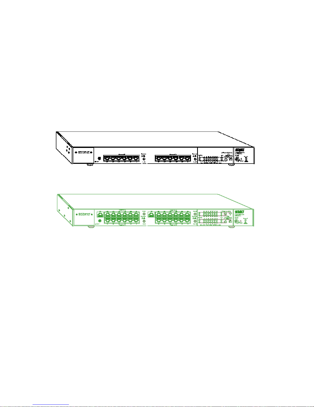
Since all the TigerStack hubs have the same footprint, only two
— the TigerStack 3312TA and 3326TA — are shown below.
ABOUT THE HUBS
4
TigerStack 3312TA
TigerStack 3326TA
Page 16

Features
All Models
• Push-buttons or switches to segment each hub into independent networks
• Front panel LEDs for “status-at-a-glance” troubleshooting:
• Power — one per hub
• NMM — one per hub
• Collision — one per segment
• Segment —one per segment
• Port Status (Link/Partition/Source) — one per port
• Automatic port/segment partitioning and reconnection for
physical level network management and fault tolerance
• Internal transmit/receive crossover on all twisted-pair ports
for connection to adapters with straight-through wiring
• Crossover enable/disable function on one twisted-pair port
in each segment to uplink to a LAN switch or cascade to
another hub with straight-through wiring
• Automatic polarity detection and correction on 10BASE-T
receive pairs to correct miswiring and make connections
simple and quick
• Link integrity checking on all twisted-pair connections
• Smart squelch digital noise filter on all 10BASE-T ports
• Extended distance support for both 10BASE-T and thin coax
cable
• Jabber lock-up protection to prevent overly long
transmissions
• Rack-, table-, or wall-mount chassis design for installation
flexibility
• Internal, auto-ranging power supply
• Reliable point-to-point connections
5
ABOUT THE HUBS
Page 17

Models 3312TA and 3326TA
The following additional features are provided by Models
3312TA and 3326TA:
• Optional Redundant Power Unit to minimize downtime in
the event of an internal power supply failure
• Two expansion slots for optional slide-in 10BASE-T, BNC,
fiber and AUI modules
• Larger segments — depending on the model, 14-, 21-, or 28port segments may be formed by combining repeater
groups
ABOUT THE HUBS
6
Page 18

CHAPTER 2
INSTALLING
7
Locating the Hub . . . . . . . . . . . . . . . . . . . . . . 8
Equipment Checklist . . . . . . . . . . . . . . . . . . . . 8
Package Contents . . . . . . . . . . . . . . . . . . . . 8
Optional Equipment . . . . . . . . . . . . . . . . . . 9
Required Rack-Mounting Tools . . . . . . . . . . 9
Slide-in Modules . . . . . . . . . . . . . . . . . . . . . . . 9
Rack Mounting . . . . . . . . . . . . . . . . . . . . . . . . 10
Desktop or Shelf Mounting . . . . . . . . . . . . . . . 12
Stacking . . . . . . . . . . . . . . . . . . . . . . . . . . . . . 13
Connecting Power . . . . . . . . . . . . . . . . . . . . . . 15
Page 19

Locating the Hub
The hub can be installed in a standard 19-inch equipment rack,
or on a desktop or shelf. Be sure to follow the guidelines
below when choosing a location:
• Select a suitable location for the hub:
• It should be accessible for installing, cabling, and maintaining the hub.
• The temperature and humidity should be within the
ranges listed in Appendix A.
• The status LEDs should be clearly visible.
• There should be adequate space (approximately two
inches) on all sides for proper air flow.
• Make sure twisted-pair cable is always routed away from
power lines, fluorescent lighting fixtures, and other sources
of electrical interference such as radios, transmitters, etc.
• Make sure that a separate grounded power outlet is within 8
feet (2.44 m) of the hub and is powered from an independent circuit breaker. As with any equipment, using a filter
or surge suppressor is recommended.
Equipment Checklist
Package Contents
Check that the following equipment is included in your
package:
• The TigerStack hub
• Bracket Mounting Kit, containing two brackets and four
screws for attaching the brackets to the hub
• Four adhesive feet
• This User Guide
• One SMC Warranty Registration Card — be sure to complete
and return this card within 90 days to extend the three-year
warranty to a lifetime warranty
• The appropriate power cord for your country — either US,
Continental or UK
8
INSTALLING
Page 20

Optional Equipment
The following equipment is not provided:
• Stacking cable, order number SMC3300-CABLE — one is
required for each hub you want to stack
• Rack-mounting screws — four are required for each hub
you want to mount in a rack
Required Rack-Mounting Tools
Be sure to have the following tools available when rack mounting your hub:
• Screws for mounting the hub in a rack (not included)
• A screwdriver (Phillips-head or flathead, depending on type
of screws used)
Slide-in Modules
(Models 3312TA and 3326TA Only)
SMC’s TigerStack 3312TA and 3326TA hubs are equipped with
two expansion slots (port 7, port 14) for slide-in modules. AUI,
10BASE2, 10BASE-T and 10BASE-F modules are available.
Port 7 is accessible from the front panel and port 14 is located
on the rear of the hubs.
If you have purchased a slide-in module for port 7 and/or 14,
install the module(s) now. Follow the installation instructions
provided in the slide-in module package.
9
INSTALLING
Page 21
Rack Mounting
Before rack mounting the hub, pay particular attention to the
following factors:
• Temperature: Since the temperature within a rack assem-
bly may be higher than the ambient room temperature,
check that the rack-environment temperature is within the
operating temperature range specified in Appendix A.
• Mechanical Loading: Do not place any equipment on top
of a rack-mounted unit.
• Circuit Overloading: Be sure that the supply circuit to the
rack assembly is not overloaded.
• Grounding: Rack-mounted equipment should be properly
grounded. Particular attention should be given to supply
connections other than direct connections to the mains.
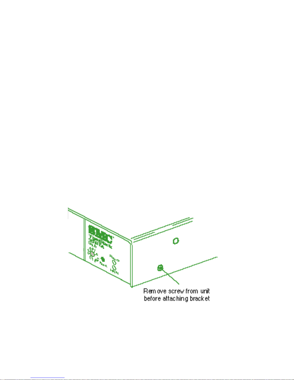
To rack mount the hub:
1. Remove the two screws from the sides of the unit.
Removing the Screws
2. Attach the brackets using the screws provided in the Bracket
Mounting Kit.
10
INSTALLING
Page 22
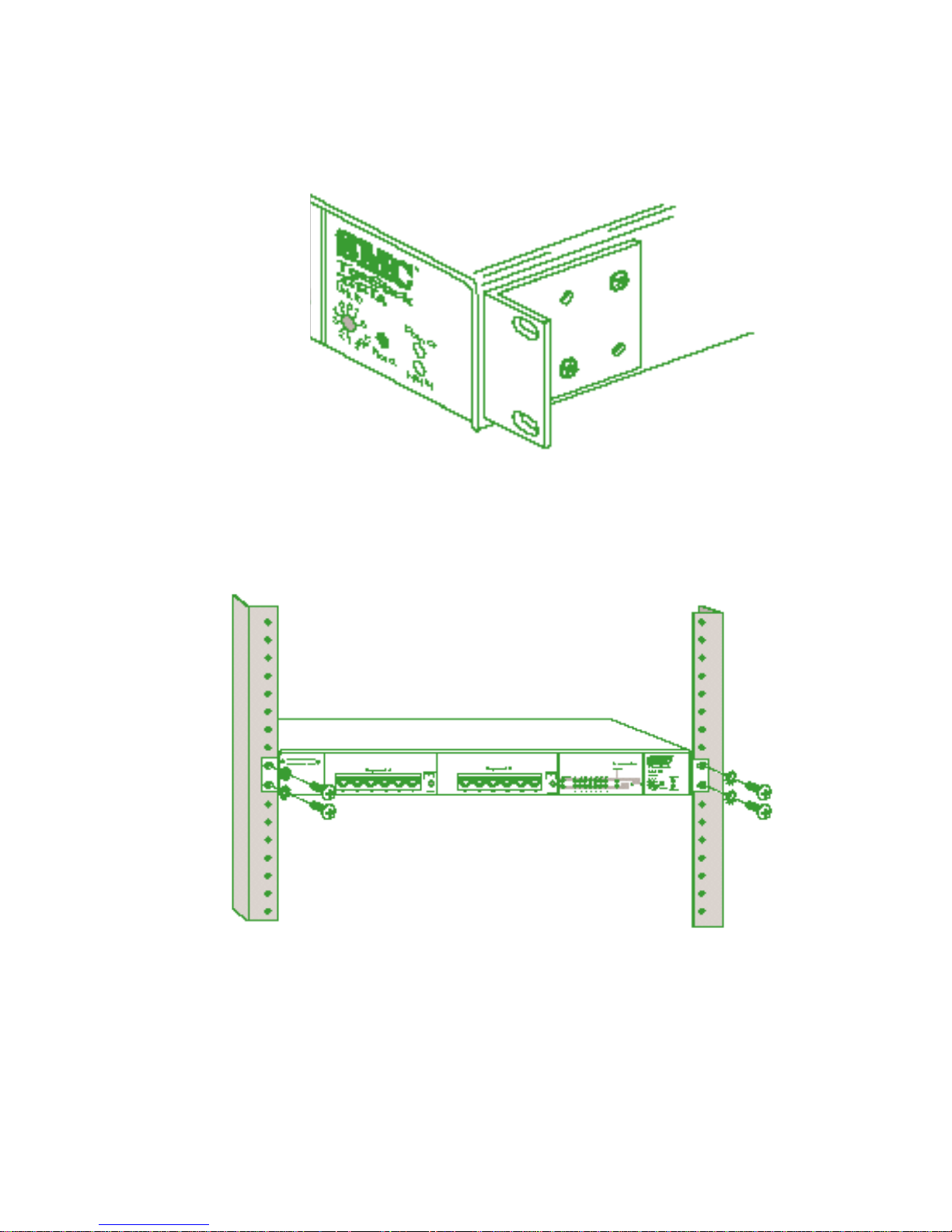
Attaching the Brackets
3. Install the hub in the rack, using four rack-mounting screws
(not provided).
Installing the Hub in a Rack
4. If stacking hubs, install the remaining hubs in the rack, one
atop the other. Then go to “Stacking” later in this chapter.
5. If installing a single hub, go to “Connecting Power” at the
end of this chapter.
11
INSTALLING
Page 23
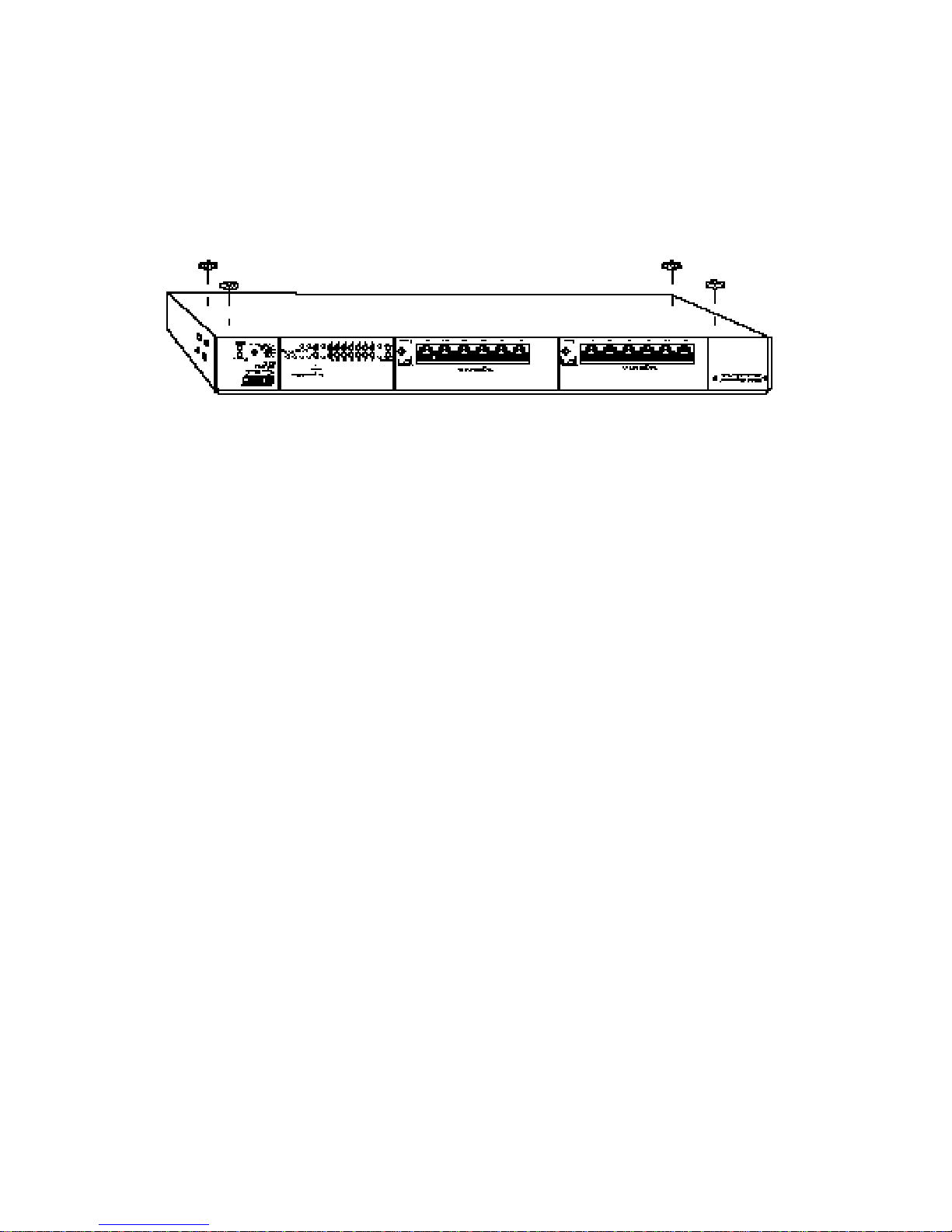
Desktop or Shelf Mounting
1. Attach the four adhesive feet to the bottom of the hub.
Attaching the Adhesive Feet
2. Set the hub on a flat surface near an AC power source,
making sure there are at least two inches of space on all
sides for proper air flow.
3. If stacking hubs, install four adhesive feet on each unit and
place each hub squarely on top of the hub below. Then go
to “Stacking” on the next page of this chapter.
4. If installing a single hub, go to “Connecting Power” later in
this chapter.
INSTALLING
12
Page 24

Stacking
The hubs can be stacked as many as eight high, and all models
can be mixed in the same stack, in any order or combination.
Note: Although hubs can be stacked after being connected to
a power source, it is not recommended as a safe networking practice.
Before stacking the hubs, pay attention to the following guidelines:
• Be sure to have one stacking cable for each hub you want
to stack. This cable (order number SMC3300-CABLE) is not
provided with the hub, and must be ordered separately.
• If an NMM is installed in one of the hubs, be sure to set
the Unit ID switch on each hub in the stack to a unique
number. See your NMM User Guide for instructions about
setting the Unit ID switch.
To stack the hubs:
1. Locate the SCSI connectors labeled “A” and “B” on the rear
of each hub (refer to the the illustration on the next page).
2. Attach one end of the stacking cable to the SCSI connector
labeled “B” on the right hand side of the lower hub. Attach
the other end of the cable to the left connector labeled “A”
on the upper hub.
3. Repeat Step 2 until all the hubs (maximum eight) have been
stacked.
4. Go to “Connecting Power” at the end of this chapter.
13
INSTALLING
Page 25

Stacking the Hubs
INSTALLING
14
Page 26

Connecting Power
Note: It is recommended that the hubs be stacked before
power is applied.
To connect each hub to a power source:
1. Insert the power cable plug directly into the receptacle
located at the back of the hub.
Power Connector on Rear of Hub
2. Plug the other end of the cable into the appropriate
receptacle.
Note: For international use, you may need to change the AC
line cord. You must use a line cord set for the receptacle type in your country. The cord should be HARCertified, and the mark HAR should appear on the outer
sheath or jacket, or on the insulation of one of the inner
conductors. The female receptacle of the cord set must
meet CEE-22 requirements. If you have any questions
concerning the proper power cord to use, please contact your local SMC Supplier.
3. Check the front panel LEDs. At power on, the:
• Power LED — lights and remains on.
• NMM LED:
• If the NMM is installed, this LED blinks green for a
few seconds during power-on diagnostics, then turns
solid green. If diagnostics fail, the LED blinks yellow.
• If the NMM is not installed, the LED remains off.
15
INSTALLING
Page 27

• Segment LEDs — flash yellow, then change to the color
indicating the position of the Segment switch.
• Port Status LEDs:
• 10BASE-T and Dual ST LEDs flash yellow and then
go off. Once testing is complete, these LEDs indicate
port activity.
• AUI and BNC LEDs turn green after the power-on
sequence and remain on until a data packet has been
passed successfully. If the BNC port is not terminated, the BNC LED will light yellow and the port
will partition due to excessive collisions.
• Collision LEDs — turn yellow for a fraction of a sec-
ond, then go off. Once testing is complete these LEDs
indicate network activity.
Refer to Chapter 5, “Troubleshooting,” for more information
about the LEDs.
4. For TigerStack 3312TA and 3326TA Only – If you have
purchased one or more Redundant Power Units, connect
them to these devices and to an AC power source now, following the instructions included with the package.
INSTALLING
16
Page 28

Making Network Connections . . . . . . . . . . . . . 18
Directly . . . . . . . . . . . . . . . . . . . . . . . . . . . 18
Via Transceiver . . . . . . . . . . . . . . . . . . . . . . 18
The SMC 5 - 4 - 3 Rule . . . . . . . . . . . . . . . . 20
Connecting to Twisted-Pair Cabling . . . . . . . . . 21
Crossover Function . . . . . . . . . . . . . . . . . . . 21
Connecting Devices . . . . . . . . . . . . . . . . . . 22
Wiring Closet Connections . . . . . . . . . . . . . . 24
Connecting to Thin Coax Cabling . . . . . . . . . . 26
Connecting to Thick Coax Cabling . . . . . . . . . . 27
Connecting to Fiber Cabling . . . . . . . . . . . . . . 28
CHAPTER 3
CONNECTING
17
Page 29

Making Network Connections
Hubs are designed to link multiple workstations and other hubs
to an Ethernet network.
Directly
Hubs can be joined directly to other network devices via their
front-panel ports as long as both devices have one port with an
identical connector.
For example, the TigerStack 3312TA with its twelve 10BASE-T
ports and a slide-in BNC module can be:
• cascaded to a LAN switch or another 10BASE-T hub via one
of its two uplink (twisted-pair, switch-selectable crossover)
ports
• connected to a 10BASE-T adapter via one of its fixed
crossover ports
• cascaded to SMC’s TigerHub™FL6, since they each have a
BNC port
• attached directly to a thin coax backbone via its BNC port
Via Transceiver
If both devices have an AUI (Attachment Unit Interface) port
(designated by the IEEE as the standard interface for 10 Mbps
Ethernet networks), they may be joined with two identical
transceivers* and a length of the appropriate type of cable.
For example, the TigerStack 3306BC hub (with its six BNC
ports, one AUI port, and one 10BASE-T port) can be:
• cascaded to another TigerStack 3306BC hub with two fiber
transceivers that are joined with a fiber link segment, to span
the distance between two buildings
* Transceivers are typically 2-port devices with one AUI connector and
one connector for a specific medium (RJ-45 for twisted pair, BNC for thin
coax, or ST for fiber).
18
CONNECTING
Page 30

Caution:When attaching a BNC transceiver to an AUI port, be
sure to disable the transceiver’s SQE switch.
Even if only one of the devices has an AUI port, it can be
joined to any port on an another device with the appropriate
transceiver and cable.
For example, the TigerStack 3306FC (with its six fiber ports,
one AUI port, and one BNC port) can be:
• connected to any 10BASE-T adapter with a 10BASE-T transceiver and a length of twisted-pair cable
To attach a transceiver to the AUI port:
1. Slide the hold-down clip on the AUI female D-Connector to
the open position.
2. Attach the transceiver to the AUI female D-Connector.
3. Slide the clip back to the closed position.
Attaching a Transceiver to the AUI Port
19
CONNECTING
Page 31

The SMC 5 - 4 - 3 Rule
When making connections, check to be sure that you do not
exceed the IEEE guidelines for Ethernet networks. The easiest
way is with the SMC 5 - 4 - 3 Rule given below.
Note: This rule is completely consistent with the IEEE 802.3
specification.
20
CONNECTING
Between any two PCs or other stations on the network, there
may be:
• up to 5 cable segments in series,
• up to 4 repeaters (hubs or multi-port concentrators),
• up to 3 populated cable segments, that is, segments
attached to two or more PCs (coax networks only).*
* The remaining two segments are unpopulated; these are
known as inter-repeater links or IRLs. Remember, this distinction between populated and unpopulated segments is
significant for coax networks only.
Page 32

Connecting to Twisted-Pair Cabling
A twisted-pair cable segment is used for point-to-point connections. With it, you can cascade a pair of hubs, link a hub to a
LAN switch, or connect a hub to an adapter.
Crossover Function
Every twisted-pair connection must have a wiring crossover to
transmit and receive data. This crossover can be implemented
in the wiring or the device itself.
For convenience, the crossover is already built into the
10BASE-T ports that are labeled with an “X” — these are called
fixed crossover ports. Adapters can be connected to these
ports with straight-through cable.
Additionally, one twisted-pair port in each segment on the
10BASE-T TigerStack hubs, and the lone twisted-pair port on
the thin coax model, features a crossover enable/disable button
— these are called uplink or switch-selectable crossover ports.
When the wiring crossover is disabled, other 10BASE-T hubs
and LAN switches can be connected to these ports with
straight-through cable.
The locations of the crossover buttons on the TigerStack
3326TA are shown below. Buttons for the other models appear
in a similar position.
Crossover Buttons
21
CONNECTING
Page 33

When a port labeled with an “X” is connected to a device that
does not support the crossover function, straight-through
cabling can be used. However, when connecting two identical
ports (that is, ports that either both support or do not support
the crossover function), the crossover must be implemented in
the wiring. This is summarized in the following table:
A list of the fixed and switch-selectable crossover (uplink) ports
for each TigerStack model can be found in the following table:
Connecting Devices
Adapters, other hubs, and LAN switches are connected to
10BASE-T ports of a TigerStack hub with a twisted-pair cable
segment. If the hub is located in a wiring closet, the connection to an adapter is made via a patch cable, modular wall outlet, punch-down block, and patch panel.
22
CONNECTING
Crossover/Straight-Through Wiring Requirements
If one port is... And the other port is... Then use...
Crossover (X) Crossover (X) Crossover cable
Crossover (X) Straight-through Straight-through cable
Straight-through Straight-through Crossover cable
RJ-45 Fixed Crossover and Uplink Ports
Port Numbers
Model Fixed Crossover Uplink
3312TA 1-5, 8-12 6, 13
3326TA 1-5, 8-12, 15-20, 22-27 6, 13, 21, 28
3314T 1-6, 8-13 7, 14
3328T 1-6, 8-13, 15-20, 22-27 7, 14, 21, 28
3328TELCO N/A 7, 14, 21, 28
3306BC N/A 8
Page 34

Caution: Regulations regarding the connection of equipment to
telephone networks vary from country to country.
Check with your local telephone network supplier
before using existing telephone wiring.
Note: Refer to the table on the preceding page to determine
whether you need straight-through or crossover cable.
To connect a device to a 10BASE-T port on a TigerStack hub:
1. Attach one end of a twisted-pair cable segment to the
device’s RJ-45 connector.
10BASE-T Connections
2. If the device is another hub or a LAN switch, attach the
other end of the cable segment to an open 10BASE-T port
on the hub.
3. If the device is an adapter and the TigerStack hub is in a
wiring closet, attach the other end of the cable segment to
a 10BASE-T modular wall outlet that is connected to the
wiring closet (see “Wiring Closet Connections“ on the
next page). Otherwise, attach the other end to an open
10BASE-T port on the hub.
23
CONNECTING
Page 35

Wiring Closet Connections
If the TigerStack hub has RJ-45 connectors:
1. Attach one end of a 50-pin Telco cable to the punch-down
block in the wiring closet, and the other end to the patch
panel on the rack.
2. Attach one end of the patch cable to the patch panel, and
the other end to an open 10BASE-T port on the hub.
3. Label the cables to simplify future troubleshooting.
Wiring Closet Connections via RJ-45 Connectors
24
CONNECTING
Page 36

If the TigerStack hub has Telco connectors:
1. Attach one end of a 50-pin Telco cable to the punch-down
block in the wiring closet
2. Attach the other end to the 50-pin connector on the
TigerStack 3328Telco hub.
Wiring Closet Connections via Telco Connectors
25
CONNECTING
Page 37

Connecting to Thin Coax Cabling
Up to 30 devices (hubs, workstations, servers, etc.) may
be connected to a thin coax cable segment with BNC
T-Connectors.
Each cable segment must be terminated at both ends by a 50
ohm BNC terminator. One of the terminators must be grounded.
Note: TigerStack hub BNC ports support extended distance
capability up to 305 m (1,000 ft.) with cable meeting certain specifications (see Appendix B, “Cables”). However ,
if other devices are attached to the same cable segment,
then the maximum length of the cable segment is limited
to the length supported by those products.
To connect a TigerStack BNC port to a thin coax cable
segment:
1. Attach the male end of a BNC T-Connector to the BNC port.
2. Connect one end of a length of thin coax cable to one side
of the BNC T-Connector.
3. Connect either another length of thin coax cable or a
50-ohm BNC terminator to the other side of the BNC
T-Connector.
Thin Coax Connection via BNC Port
26
CONNECTING
Page 38

Connecting to Thick Coax Cabling
Up to 100 devices (hubs, workstations, servers, etc.) may be
attached to a thick coax cable segment using AUI drop cables
and tap-type transceivers.
Each cable segment must be terminated at both ends by a 50
ohm N-Series terminator. One terminator must be grounded.
To connect a TigerStack AUI port to a thick coax cable
segment:
1. Attach a tap-type transceiver to the thick coax cable segment. Refer to the documentation provided with the transceiver for installation instructions.
2. Connect one end of the AUI drop cable to the tap-type
transceiver, and the other end to the AUI port on the hub.
Slide the hold-down clip on the female D-Connector to the
open position, attach the male D-Connector, and then slide
the clip back to the closed position.
Thick Coax Connection via AUI Port
27
CONNECTING
Page 39

Connecting to Fiber Cabling
A fiber cable segment is used for point-to-point connections.
When using two simplex cables:
1. Connect one end of the first cable to the hub’s Tx connector
and the other end to the Rx connector on the other device.
2. Connect one end of the second cable to the hub’s Rx connector and the other end to the Tx connector on the other
device.
When using one duplex cable:
1. Differentiate the two fiber strands by banding one strand at
both ends, as shown below.
2. Connect one end of the banded strand to the hub’s Tx connector and the other end to the Rx connector on the other
device.
3. Connect one end of the remaining strand to the hub’s Rx
connector and the other end to the Tx connector on the
other device.
Duplex Fiber Connections via Dual ST Port
28
CONNECTING
Page 40

The Segmentation Concept . . . . . . . . . . . . . . . 30
Isolating Segments . . . . . . . . . . . . . . . . . . . 31
Interconnecting Isolated Segments . . . . . . . . 33
Segmenting the Hub . . . . . . . . . . . . . . . . . . . . 34
Procedure . . . . . . . . . . . . . . . . . . . . . . . . . . 36
CHAPTER 4
SEGMENTING
29
Page 41

The Segmentation Concept
Each TigerStack hub is composed of two or four repeater
groups, with each group containing four or seven ports, depending upon the model. Thus, a stack eight high can have as
many as 32 repeater groups. Initially, these groups are united
into a single 10 Mbps segment via the inter-repeater bus which
runs through the stacking cable.
SEGMENTING
30
3306FC Segments A and B
3306BC Segments A and B
3328TELCO Segments A, B, C, and D
3328T Segments A, B, C, and D
(the 3314T has Two Segments: A and B)
3326TA Segments A, B, C, and D
(the 3312TA has Two Segments: A and B)
Page 42

Isolating Segments
Suppose you have a number of small, high-traffic workgroups
that do not need to share data but do need additional bandwidth. Each workgroup can be attached to a different repeater
group. Then the repeater groups can be isolated from the bus
to form independent 10 Mbps networks (also known as collision domains or segments).
Microsegmentation is accomplished via front panel buttons or
switches, depending on the model. A LED for each segment
indicates the status of that segment.
Note: With the NMM installed, repeater groups can also be iso-
lated through EliteView, SMC’s SNMP-based management software.
A stack can have as many as 32 separate 10 Mbps segments.
These segments can be isolated from, and rejoined to, the bus
quickly and easily via their front panel buttons or switches, or
under SNMP software control.
31
SEGMENTING
TigerStack
Segments 1-32
Segmenting the Stack
Page 43

32
3326TA Segment Switches A, B, C, and D
(the 3312TA has Two Switches: A and B)
3328TELCO Segment Buttons A, B, C, and D
3306BC Segment Buttons A and B
SEGMENTING
3328T Segment Buttons A, B, C, and D
(the 3314T has Two Buttons: A and B)
Page 44

Interconnecting Isolated Segments
Suppose you have a number of small, high-traffic workgroups
that do need to share data and also need additional bandwidth.
Once isolated from the bus, these workgroups can be interconnected through a switch.
Linking 10BASE-T Segments Through a Switch
33
SEGMENTING
3306FC Segment Buttons A and B
Switch
Servers
Workstations
TigerStack
Multiple
10 Mbps
Uplinks
Page 45

Segmenting the Hub
The hub can be segmented either via hardware with the front
panel switches (TA models) or buttons (all other models), or
via software with EliteView or any other SNMP-based manager.
Note: Unless the hardware lockout feature has been enabled
via software, the latest action (either hardware or software) overrides the previous setting.
Each segment button has two positions: Enable ON and Enable
OFF. Each segment switch has three positions: Hub, Stack and
Isolate. The figure on the following page illustrates how these
buttons and switches can be used to segment the hubs. These
functions are defined in the table on the next page.
Model 3328T (bottom) contains four segment buttons. The
buttons for segments A and C are in the Enable OFF position,
so these segments are not isolated; they are connected to the
inter-repeater bus. The buttons for segments B and D are in
the Enable ON position, so these segments are removed or
isolated from the inter-repeater bus and from each other.
Model 3312TA (middle) contains two segment switches. The
switches for both segments are in the Hub position so these
segments are joined together to form a single 14-port segment.
Model 3326TA (top) contains four segment switches. The
switch for segment D is in the Stack position, so segment D is
connected to the stack through the inter-repeater bus. The
switch for segment C is in the Isolate position, so segment C is
removed from the inter-repeater bus. The switches for
segments A and B are in the Hub position, so these segments
are joined to form a 14-port segment.
SEGMENTING
34
Page 46

35
SEGMENTING
Segmenting the Hubs
Segment Button/Switch Functions
Button Switch Function
Off Stack Connects segment to the stack
On Isolate Isolates segment from the stack
-- Hub Joins hub segments to form larger collision
domain
Page 47

Procedure
Models 3314T, 3328T, 3328TELCO, 3306BC, 3306FC
1. To isolate a segment, move the button labeled Segmentation
Enable to the On position (out).
2. Either press the Reset button (using a small, pointed instrument) or power the hub off, then on again.
Models 3312TA and 3326TA
1. Move the 3-position switch to one of the following positions:
Stack – Select Stack to connect the segment to the stack via
the inter-repeater bus. The Select LED will be off.
Hub – Select Hub to isolate the segment from the hub and
to combine it with the other segments in the hub that have
been set similarly, forming a larger segment. The Select
LED will be green.
Isolate – Select Isolate to completely isolate the segment.
The Select LED will be yellow.
2. Either press the Reset button (using a small, pointed instrument) or power the hub off, then on again.
SEGMENTING
36
Page 48

Status/Diagnostic LEDs . . . . . . . . . . . . . . . . . . 38
Testing the Installation . . . . . . . . . . . . . . . . . . 41
CHAPTER 5
TROUBLESHOOTING
37
Page 49

Status/Diagnostic LEDs
The following front-panel LEDs aid in testing the hub and diagnosing network problems:
• One green Power LED
• One bi-color NMM Status LED
• One yellow Collision LED for each segment
• One yellow Segment LED for each segment
(Bi-color for Models 3312TA and 3326TA)
• One bi-color Port Status LED for each port
38
TROUBLESHOOTING
3312TA Front Panel LEDs
3326TA Front Panel LEDs
Page 50

39
TROUBLESHOOTING
3328TELCO Front Panel LEDs
3306BC Front Panel LEDs
3306FC Front Panel LEDs
3328T Front Panel LEDs
Page 51

The function of these LEDs is summarized in the table below:
Note: With some network adapters, the Port Status LED will light only
after the board has been initialized with the appropriate driver software (e.g., after IPX has been loaded in a NetWare environment).
TROUBLESHOOTING
40
Front Panel LEDs
LED Condition Status
Power Off No AC power
Green AC power on
NMM Off NMM not installed
Blinking Green Power-on diagnostics being
performed on NMM
Green NMM has passed power-on
diagnostics
Blinking Yellow NMM failed power-on diagnostics
Collision Off No collisions detected
(one per segment) Blinking Yellow A collision has been detected on
the network (i.e., the hub is
receiving data from two or more
nodes at the same time)
Segment Off Repeater group is connected to the
(one per segment) stack
Yellow Repeater group is segmented
(i.e., isolated from rest of stack)
Green Repeater group is combined with
other groups within the hub
(Models 3312TA and 3326TA)
Port Status Off Port not connected or wiring is
(one per port) faulty
Green:
RJ-45 / ST Link between hub and attached
device is good
BNC / AUI Loopback function is working
Blinking Green Packet data is originating from
(Source) this port
Yellow Port is partitioned
(Partition)
Page 52

Testing the Installation
1. Power up or reset the hub and check the LEDs (refer to
“Connecting Power” in Chapter 2).
2. If the Power LED is not lit and there is no activity on the
entire unit:
• Check the connections between the hub, the power
cord, and the wall outlet.
• Check the connections to the punch-down block and
patch panel (if the hub is installed in a rack).
If the Power LED still does not light, contact SMC Tech
Support.
3. If the NMM LED blinks yellow, the power-on diagnostics
have failed. Contact SMC Tech Support.
4. If the Port Status LEDs are not responding:
• Check the connections between each network device
and the hub port, including wiring.
• Check that the devices are powered on and functioning
properly.
5. If the BNC Port Status LED is yellow, be sure the cable
attached to this port is properly terminated.
Note: If the BNC port is not used, it does not need to be
terminated.
41
TROUBLESHOOTING
Page 53

42
Page 54

TigerStack 3312TA . . . . . . . . . . . . . . . . . . . . . . 44
TigerStack 3326TA . . . . . . . . . . . . . . . . . . . . . . 44
TigerStack 3314T . . . . . . . . . . . . . . . . . . . . . . . 45
TigerStack 3328T . . . . . . . . . . . . . . . . . . . . . . . 45
TigerStack 3328TELCO . . . . . . . . . . . . . . . . . . 46
TigerStack 3306BC . . . . . . . . . . . . . . . . . . . . . 46
TigerStack 3306FC . . . . . . . . . . . . . . . . . . . . . . 47
All TigerStack Hubs . . . . . . . . . . . . . . . . . . . . . 47
Stacking Cable . . . . . . . . . . . . . . . . . . . . . . . . 48
APPENDIX A
SPECIFICATIONS
43
Page 55

TigerStack 3312TA
Order Numbers
SMC3312TA (with US power cord)
SMC3312TA EUR (with Continental power cord)
SMC3312TA UK (with UK power cord)
Ports
12 10BASE-T
2 expansion slots for optional AUI, 10BASE2, 10BASE-T and
10BASE-F modules
Segments/Unit
2
Weight
7.2 lbs. (3.27 kg)
AC Input Power
Maximum: 18.5 watts (23.0 watts with NMM)
Typical: 14.8 watts (19.0 watts with NMM)
DC Input Connector
14-pin, for optional RPU
DC Input Power (from optional RPU)
Maximum: +5 V @ 1.8 A, +12 V @ 700 mA (without NMM)
+5 V @ 2.7 A, +12 V @ 800 mA (with NMM)
TigerStack 3326TA
Order Numbers
SMC3326TA (with US power cord)
SMC3326TA EUR (with Continental power cord)
SMC3326TA UK (with UK power cord)
Ports
26 10BASE-T
2 expansion slots for optional AUI, 10BASE2, 10BASE-T and
10BASE-F modules
Segments/Unit
4
44
SPECIFICATIONS
Page 56

Weight
7.6 lbs. (3.45 kg)
AC Input Power
Maximum: 26.7 watts (32.0 watts with NMM)
Typical: 21.0 watts (25.5 watts with NMM
DC Input Connector
14-pin, for optional RPU
DC Input Power (from optional RPU)
Maximum: +5 V @ 3 A, +12 V @ 700 mA (without NMM)
+5 V @ 3.9 A, +12 V @ 800 mA (with NMM)
TigerStack 3314T
Order Numbers
SMC3314T (with US power cord)
SMC3314T EUR (with Continental power cord)
SMC3314T UK (with UK power cord)
Ports
14 10BASE-T
Segments/Unit
2
Weight
4.15 lbs. (1.88 kg)
AC Input Power
Maximum: 11.0 watts (15.7 watts with NMM)
Typical: 9.8 watts (14.0 watts with NMM)
TigerStack 3328T
Order Numbers
SMC3328T (with US power cord)
SMC3328T EUR (with Continental power cord)
SMC3328T UK (with UK power cord)
Ports
28 10BASE-T
Segments/Unit
4
45
SPECIFICATIONS
Page 57

Weight
4.7 lbs. (2.13 kg)
AC Input Power
Maximum: 22.7 watts (26.0 watts with NMM)
Typical: 17.0 watts (21.5 watts with NMM)
TigerStack 3328TELCO
Order Numbers
SMC3328TELCO (with US power cord)
SMC3328TELCO EUR (with Continental power cord)
SMC3328TELCO UK (with UK power cord)
Ports
28 10BASE-T
Segments/Unit
4
Weight
4.7 lbs. (2.13 kg)
AC Input Power
Maximum: 22.7 watts (26.0 watts with NMM)
Typical: 17.0 watts (21.5 watts with NMM)
TigerStack 3306BC
Order Numbers
SMC3306BC (with US power cord)
SMC3306BC EUR (with Continental power cord)
SMC3306BC UK (with UK power cord)
Ports
6 BNC
1 10BASE-T
1 AUI
Segments/Unit
2
Weight
4.35 lbs. (1.97 kg)
SPECIFICATIONS
46
Page 58

AC Input Power
Maximum: 36.5 watts (40.0 watts with NMM)
Typical: 28 watts (34.0 watts with NMM
TigerStack 3306FC
Order Numbers
SMC3306FC (with US power cord)
SMC3306FC EUR (with Continental power cord)
SMC3306FC UK (with UK power cord)
Ports
6 ST
1 BNC
1 AUI
Segments/Unit
2
Weight
4.15 lbs. (1.88 kg)
AC Input Power
Maximum: 27.3 watts (33.88 watts with NMM)
Typical: 21.84 watts (27.1 watts with NMM)
All TigerStack Hubs
Network Interface
10BASE-T
RJ-45, 100 Ohm UTP cable (EIA/TIA categories 3, 4, 5)
10BASE2
BNC, 50 Ohm coax (RG-58A/U or RG-58C/U)
10BASE-F
Dual ST, 62.5/125 micron core duplex fiber
AUI
D-Type 15-pin female, multi 78 Ohm STP with overall shield
Size
1.75 in. H x 16.875 in. W x 9.00 in. D
(4.4 cm x 43.2 cm x 22.9 cm)
Temperature
Operating: 0˚ to 45˚ C (32˚ to 113˚ F)
Storage: 0˚ to 85˚ C (32˚ to 185˚ F)
47
SPECIFICATIONS
Page 59

Relative Humidity, non-condensing
Operating: 0% to 90%
Storage: 0% to 95%
Power Supply
Internal, auto-ranging transformer
100 to 240 VAC, 50 to 60 Hz
Compliances
Safety
UL 1950
EN60950 (TÜV)
CSA 22.2 No. 950
Emissions
FCC Class A
Canada Department of Communications, Class A
EN55022 (CISPR 22) Class A
VCCI Class 1
Immunity
EN50082-1
Standards
IEEE 802.3
ISO/IEC 8802-3
Warranty
Unit
Limited Lifetime
Power Supply and Fan
5 years
Stacking Cable
Order Number
SMC3300-CABLE
Connector
50-pin conductor
Cable
SCSI
SPECIFICATIONS
48
Page 60

Types/Connectors . . . . . . . . . . . . . . . . . . . . . . 50
Cable Specifications . . . . . . . . . . . . . . . . . . . . . 51
Extended Distance . . . . . . . . . . . . . . . . . . . . . 53
10BASE-T Pin Assignments . . . . . . . . . . . . . . . 54
RJ-45 Connectors . . . . . . . . . . . . . . . . . . . . . 54
Telco Connectors . . . . . . . . . . . . . . . . . . . . 55
Automatic Polarity Detection and Correction . 57
Straight-Through Wiring . . . . . . . . . . . . . . . 57
Crossover Wiring . . . . . . . . . . . . . . . . . . . . 60
AUI Pin Assignments . . . . . . . . . . . . . . . . . . . . 63
APPENDIX B
CABLES
49
Page 61

Types/Connectors
CABLES
50
Cable Type Connectors
10BASE-T 100 ohm UTP, male 8-pin RJ-45
(Twisted-Pair) 22 - 26 AWG, or 50-pin Telco
0.4 - 0.6 mm,
2 pairs
AUI External male 15-pin, D-type, AUI
Transceiver Drop
Thick Coax 50 ohm Coax N-Series
Thin Coax RG-58A/U or Bayonet style BNC
RG-58C/U
50 ohm Coax
Dual Fiber 50/125, 62.5/125, Bayonet style Dual ST
80/125 or 100/140
Micron Core
Cable Types and Connectors
Page 62

Cable Specifications
51
CABLES
Type 100 ohm UTP
(e.g., IBM Type 3 or AT&T DIW)
Number of Pairs 2
Max. Link Segment Length 328 ft. (100 m)
Min. Link Segment Length 2.0 ft. (0.6 m)
Max. Number of Attachments 2
per Link Segment
Type 78 ohm STP
Max. Drop Cable Length 165 ft. (50 m)
Min. Drop Cable Length 0.0 ft. (0.0 m)
Max. Number of Attachments 2
per Drop Cable
Type 50 ohm Coax
Max. Segment Length 1,640 ft. (500 m)
Min. Distance Between 8.2 ft. (2.5 m)
Transceivers
Max. Number of Attachments 100
per Cable Segment
Twisted-Pair Link Segment Specifications
Thick Coax Cable Specifications
AUI Cable Specifications
Page 63

* See “Extended Distance.”
52
Type 50/125, 62.5/125, 80/125
100/140 micron core
Number of Pairs 2
Max. Link Segment Length 0.62 mi. (1.0 km)
Min. Link Segment Length no minimum
Max. Number of Attachments 2
per Link Segment
CABLES
Type RG-58A/U or RG-58C/U Coax
Max. Segment Length 1,000 ft.* (305 m)
Min. Distance Between 1.5 ft. (0.5 m)
Devices
Max. Number of Attachments 30
per Cable Segment
Thin Coax Cable Specifications
Duplex Fiber Cable Specifications
Page 64

Extended Distance
The IEEE 802.3 10BASE2 specification defines the maximum
length of a thin coax segment as 607 feet (185 m). However,
TigerStack BNC ports support thin coax segments of up to
1,000 feet (305 m) in length with 50 ohm RG-58 cabling meeting the following specifications:
Note: If other Ethernet products are attached to the same
cable segment, then the maximum length of that cable
segment is limited by the length these products support.
53
CABLES
Number of Nodes Nominal Attenuation at 10 MHz
per 1,000 feet (305 m) per 100 feet (30 m)
Maximum 10 13 dB or less 1.3 dB or less
Maximum 30 12 dB or less 1.2 dB or less
Extended Distance Specifications
Page 65

10BASE-T Pin Assignments
Caution: Regulations regarding the connection of equipment to
telephone networks vary from country to country.
Check with your local telephone network supplier
before using existing telephone wiring.
An Ethernet twisted-pair link segment requires two pairs of
wires. Each wire pair is identified by two different colors. For
example, one wire might be red and the other, red with white
stripes.
Caution: Each wire pair must be attached to the RJ-45 connec-
tors in a specific orientation (see “Crossover Function”
in Chapter 3 for an explanation).
RJ-45 Connectors
Each twisted-pair link segment must have an RJ-45
male connector attached to
both ends. According to the
10BASE-T specification,
pins 1 and 2 are used for
transmitting data, and pins 3
and 6 for receiving data.
* The “+” and “-” signs are used to represent the polarity of the two
wires that make up each wire pair.
Note how the
pins are numbered. Be sure
to hold the connectors in the
same orientation
when attaching
the wires to the
pins.
54
CABLES
Pin Number Assignment*
1 Tx+
2 Tx3 Rx+
6 Rx-
RJ-45 Pin Assignments
RJ-45 Connector Pin Numbers
Page 66

Telco Connectors
Twisted-pair wiring is available in bundles of twenty-five wire
pairs. A bundle requires 50-pin Telco male connectors at each
end.
Note how the pins are numbered on the 50-pin female connector shown below. Be sure to hold the 50-pin male connector
in the same orientation when attaching it to the hub.
The TigerStack 3328TELCO is equipped with two Telco connectors: the first for ports 1 to 6 and 8 to 13, and the second for
ports 15 to 20 and 22 to 27. The table on the following page
provides the pin assignments for both connectors.
55
CABLES
25-Pair Telco Connector Pin Numbers
Page 67

* The “+” and “-” signs are used to represent the polarity of the two
wires that make up each wire pair.
CABLES
56
50-Pin Telco Pin Assignments
Pin
Number
Ports
Assign-
ment*
Pin
Numbers
Ports
Assign-
ment*
1 1, 15 Rx- 26 1, 15 Rx+
2 1, 15 Tx- 27 1, 15 Tx+
3 2, 16 Rx- 28 2, 16 Rx+
4 2, 16 Tx- 29 2, 16 Tx+
5 3, 17 Rx- 30 3, 17 Rx+
6 3, 17 Tx- 31 3, 17 Tx+
7 4, 18 Rx- 32 4, 18 Rx+
8 4, 18 Tx- 33 4, 18 Tx+
9 5, 19 Rx- 34 5, 19 Rx+
10 5, 19 Tx- 35 5, 19 Tx+
11 6, 20 Rx- 36 6, 20 Rx+
12 6, 20 Tx- 37 6, 20 Tx+
13 8, 22 Rx- 38 8, 22 Rx+
14 8, 22 Tx- 39 8, 22 Tx+
15 9, 23 Rx- 40 9, 23 Rx+
16 9, 23 Tx- 41 9, 23 Tx+
17 10, 24 Rx- 42 10, 24 Rx+
18 10, 24 Tx- 43 10, 24 Tx+
19 11, 25 Rx- 44 11, 25 Rx+
20 11, 25 Tx- 45 11, 25 Tx+
21 12, 26 Rx- 46 12, 26 Rx+
22 12, 26 Tx- 47 12, 26 Tx+
23 13, 27 Rx- 48 13, 27 Rx+
24 13, 27 Tx- 49 13, 27 Tx+
25 nc nc 50 nc nc
Page 68

Automatic Polarity Detection and Correction
If a receive data pair has the “+” and “-” signals inadvertently
switched, the hubs correct the signal inversion automatically,
allowing the data path to operate correctly.
Straight-Through Wiring
If the twisted-pair link segment is to join two ports and only
one of the ports has an internal crossover, the two pairs of
wires must be straight-through.
Pin assignments for Telco connectors are given on the next
page.
57
CABLES
End 1 End 2
1 (Tx+) 1 (Tx+)
2 (Tx-) 2 (Tx-)
3 (Rx+) 3 (Rx+)
6 (Rx-) 6 (Rx-)
Straight-Through RJ-45 Pin Assignments
Page 69

CABLES
58
Straight-Through 50-Pin Telco Pin Assignments
Hub Port Device Equiv. RJ-45 Pin
1 (Rx-) 1 (Rx-) 2
2 (Tx-) 1 (Tx-) 6
3 (Rx-) 2 (Rx-) 2
4 (Tx-) 2 (Tx-) 6
5 (Rx-) 3 (Rx-) 2
6 (Tx-) 3 (Tx-) 6
7 (Rx-) 4 (Rx-) 2
8 (Tx-) 4 (Tx-) 6
9 (Rx-) 5 (Rx-) 2
10 (Tx-) 5 (Tx-) 6
11 (Rx-) 6 (Rx-) 2
12 (Tx-) 6 (Tx-) 6
13 (Rx-) 8 (Rx-) 2
14 (Tx-) 8 (Tx-) 6
15 (Rx-) 9 (Rx-) 2
16 (Tx-) 9 (Tx-) 6
17 (Rx-) 10 (Rx-) 2
18 (Tx-) 10 (Tx-) 6
19 (Rx-) 11 (Rx-) 2
20 (Tx-) 11 (Tx-) 6
21 (Rx-) 12 (Rx-) 2
22 (Tx-) 12 (Tx-) 6
23 (Rx-) 13 (Rx-) 2
24 (Tx-) 13 (Tx-) 6
25 (nc) nc (nc) nc
Page 70

59
CABLES
Straight-Through 50-Pin Telco Pin Assignments - Continued
Hub Port Device Equiv. RJ-45 Pin
26 (Rx+) 1 (Rx+) 1
27 (Tx+) 1 (Tx+) 3
28 (Rx+) 2 (Rx+) 1
29 (Tx+) 2 (Tx+) 3
30 (Rx+) 3 (Rx+) 1
31 (Tx+) 3 (Tx+) 3
32 (Rx+) 4 (Rx+) 1
33 (Tx+) 4 (Tx+) 3
34 (Rx+) 5 (Rx+) 1
35 (Tx+) 5 (Tx+) 3
36 (Rx+) 6 (Rx+) 1
37 (Tx+) 6 (Tx+) 3
38 (Rx+) 8 (Rx+) 1
39 (Tx+) 8 (Tx+) 3
40 (Rx+) 9 (Rx+) 1
41 (Tx+) 9 (Tx+) 3
42 (Rx+) 10 (Rx+) 1
43 (Tx+) 10 (Tx+) 3
44 (Rx+) 11 (Rx+) 1
45 (Tx+) 11 (Tx+) 3
46 (Rx+) 12 (Rx+) 1
47 (Tx+) 12 (Tx+) 3
48 (Rx+) 13 (Rx+) 1
49 (Tx+) 13 (Tx+) 3
50 (nc) nc (nc) nc
Page 71

Crossover Wiring
If the twisted-pair link segment is to join two ports and either
both ports are labeled with an “X” or neither port is labeled
with an “X,” a crossover must be implemented in the wiring.
Pin assignments for Telco connectors are given on the next
page.
CABLES
60
End 1 End 2
1 (Tx+) 3 (Rx+)
2 (Tx-) 6 (Rx-)
3 (Rx+) 1 (Tx+)
6 (Rx-) 2 (Tx-)
Crossover RJ-45 Pin Assignments
Page 72

61
CABLES
Crossover 50-Pin Telco Pin Assignments
Hub Port Device Equiv. RJ-45 Pin
1 (Rx-) 1 (Tx-) 6
2 (Tx-) 1 (Rx-) 2
3 (Rx-) 2 (Tx-) 6
4 (Tx-) 2 (Rx-) 2
5 (Rx-) 3 (Tx-) 6
6 (Tx-) 3 (Rx-) 2
7 (Rx-) 4 (Tx-) 6
8 (Tx-) 4 (Rx-) 2
9 (Rx-) 5 (Tx-) 6
10 (Tx-) 5 (Rx-) 2
11 (Rx-) 6 (Tx-) 6
12 (Tx-) 6 (Rx-) 2
13 (Rx-) 8 (Tx-) 6
14 (Tx-) 8 (Rx-) 2
15 (Rx-) 9 (Tx-) 6
16 (Tx-) 9 (Rx-) 2
17 (Rx-) 10 (Tx-) 6
18 (Tx-) 10 (Rx-) 2
19 (Rx-) 11 (Tx-) 6
20 (Tx-) 11 (Rx-) 2
21 (Rx-) 12 (Tx-) 6
22 (Tx-) 12 (Rx-) 2
23 (Rx-) 13 (Tx-) 6
24 (Tx-) 13 (Rx-) 2
25 (nc) nc (nc) nc
Page 73

62
CABLES
Crossover 50-Pin Telco Pin Assignments - Continued
Hub Port Device Equiv. RJ-45 Pin
26 (Rx+) 1 (Tx+) 3
27 (Tx+) 1 (Rx+) 1
28 (Rx+) 2 (Tx+) 3
29 (Tx+) 2 (Rx+) 1
30 (Rx+) 3 (Tx+) 3
31 (Tx+) 3 (Rx+) 1
32 (Rx+) 4 (Tx+) 3
33 (Tx+) 4 (Rx+) 1
34 (Rx+) 5 (Tx+) 3
35 (Tx+) 5 (Rx+) 1
36 (Rx+) 6 (Tx+) 3
37 (Tx+) 6 (Rx+) 1
38 (Rx+) 8 (Tx+) 3
39 (Tx+) 8 (Rx+) 1
40 (Rx+) 9 (Tx+) 3
41 (Tx+) 9 (Rx+) 1
42 (Rx+) 10 (Tx+) 3
43 (Tx+) 10 (Rx+) 1
44 (Rx+) 11 (Tx+) 3
45 (Tx+) 11 (Rx+) 1
46 (Rx+) 12 (Tx+) 3
47 (Tx+) 12 (Rx+) 1
48 (Rx+) 13 (Tx+) 3
49 (Tx+) 13 (Rx+) 1
50 (nc) nc nc nc
Page 74

AUI Pin Assignments
Note: Voltage Plus (VP) and Voltage Common (Vc) use a
single twisted-pair in the AUI cable.
63
CABLES
Pin Circuit Signal Name
3 DO-A Data Out Circuit A
10 DO-B Data Out Circuit B
11 DO-S Data Out Circuit Shield
5 DI-A Data In Circuit A
12 DI-B Data In Circuit B
4 DI-S Data In Circuit Shield
8 CO-S Control Out Circuit Shield
2 CI-A Control In Circuit A
9 CI-B Control In Circuit B
1 CI-S Control In Circuit Shield
6 Vc Voltage Common
13 VP Voltage Plus
14 VS Voltage Shield
Shell PG Protective Ground
(Conductive Shell)
AUI Pin Assignments
Page 75

64
Page 76

65
A
AC line cord 15
Adhesive feet 8, 12
Attaching
adhesive feet 12
BNC transceiver 19
brackets 11
power cord 15
transceiver to AUI port 19
AUI
attaching transceiver to 19
drop cable 27
pin assignments 63
port 18, 19, 27, 50
Automatic
polarity detection and
correction 5, 57
port/segment partitioning
and reconnection 5
B
Bandwidth
boosting 2, 31
scaling 2, 33
BNC
connector 26, 50
transceiver, SQE switch 19
Boosting bandwidth 2, 31
Bracket Mounting Kit 8
Brackets, attaching 11
Buttons
crossover 21
segment 5, 31-36
C
Cable
connectors 50
crossover 21, 22, 60
specifications 51, 52
straight-through 21, 22, 57
types 50
INDEX
Cable segment
IRL (Inter-Repeater Link) 20
populated 20
unpopulated 20
Cascading hubs 18
Changing AC line cord 15
Checklist, equipment 8
Collision
domain, definition of 2
LEDs 5, 16, 38-40
Compliances v, 48
Connecting to
adapters 18
fiber cable 28
LAN switch 33
network 18
other hubs 18
power source 13, 15
telephone networks 23, 54
thick coax cable 27
thin coax cable 26
twisted-pair cable 21, 23
wiring closet 22-25
Connectivity
SMC 5 - 4 - 3 Rule 20
Connectors
AUI 18, 19, 27, 50
BNC 26, 50
RJ-45 23, 50
SCSI 13, 14
ST 28, 50
Telco 24, 25, 50, 55
Crossover
buttons 21
function 21
pin assignments
RJ-45 60
Telco 61, 62
wiring 60
wiring requirements 22
Page 77

66
D
Desktop mounting 12
Diagnostics, power-on 15
Distance, extended 5, 26, 53
Drop cable, AUI 27
Duplex cable, fiber 28
E
Equipment checklist 8
Extended distance 5, 26, 53
F
Fiber
cable connections 28
cable specifications 52
connector 28, 50
Fixed crossover ports 5, 21, 22
Front Panel LEDs 38, 39
H
Hubs
cascading 18
installing 8-12
locating 8, 10
managing 3
stacking 2, 13-15
I
Installing hubs 8-12
Interconnecting
repeater groups 2, 33
segments 2, 33
International line cords 15
IRL (Inter-Repeater Link) 20
Isolating segments
via hardware 31, 34-36
via software 31, 34
J
Jabber lockup protection 5
INDEX
L
LAN switch 33
LEDs
Collision 5, 16, 38-40
NMM 5, 15, 38-41
Port Status 5, 16, 38-41
Power 5, 15, 38-41
power-up sequence 15
Segment 5, 16, 38-40
Line cord 15
Link integrity checking 5
Locating hubs 8, 10
Logical repeater, definition of 2
M
Making network connections 18
directly 18
via transceiver 18
Making Telco connections 24, 25
Managing hubs 3
Microsegmentation 31
Mounting hubs
in a rack 10
on a desktop 12
on a shelf 12
N
Network Management Module 3
field-installable 3
placement in stack 3
NMM LED 5, 15, 38-41
O
Optional equipment 9
Overriding segmentation
settings 34
P
Package contents 8
Partitioning, automatic
port/segment 5
Page 78

Pin assignments
10BASE-T 54, 56-62
crossover 60-62
straight-through 57-59
AUI 63
Pin numbers
RJ-45 54
Telco 55
Point-to-point
connections 21, 28
Polarity
automatic detection and
correction of 5, 57
of wires 54
Populated cable segment 20
Port
AUI 18, 19, 27, 50
fixed crossover 5, 21, 22
RJ-45 23, 50
ST 28, 50
status LEDs 5, 16, 38-41
switch-selectable
crossover 5, 21, 22
uplink 5, 21, 22
Power
connecting to 13, 15
connector 15
cord, attaching 15
LED 5, 15, 38-41
supply 5
Power-on diagnostics 15, 41
Power-up LED sequence 15
R
Rack mounting
hubs 10
screws 9
site guidelines 10
tools, required 9
Reconnection, automatic
port/segment 5
Rejoining repeater groups 31
Removing screws 10
Repeater
hops 2
logical, definition of 2
Repeater groups
definition of 30
interconnecting 2, 33
isolating 2, 31
rejoining 31
segmenting 2, 31
uniting 30
RJ-45 connector 23, 50
pin assignments 54
pin numbers 54
Routing twisted-pair cable 8
S
Scaling bandwidth 2, 33
SCSI connectors 13, 14
Segment
buttons 5, 31-36
definition of 31
LEDs 5, 16, 38-40
settings, overriding 34
switches 5, 31, 32, 34-36
Segmentation hardware
lockout 34
Segmenting
hubs 2, 31, 34-36
via hardware 31, 34-36
via software 31, 34
repeater groups 2, 31
Segments
interconnecting 2, 33
isolating 31
rejoining 31
Setting unit ID switch 13
Shelf mounting 12
Simplex cable, fiber 28
Site guidelines 8, 10
67
INDEX
Page 79

Smart squelch digital noise
filter 5
SMC 5 - 4 - 3 Rule 20
Specifications
cable 51, 52
extended distance 53
hubs 44-48
network interface 47
stacking cable 48
SQE switch 19
ST connectors 28, 50
Stacking
cable 9, 13, 48
hubs 2, 13, 14, 15
Standards 48
Status/Diagnostic
LEDs 5, 15, 16, 38-40
Straight-through
pin assignments
RJ-45 57
Telco 58, 59
wiring 22, 57
wiring requirements 22
Subdividing a workgroup 2
Switch-selectable crossover
ports 5, 21, 22
Switches
segment 5, 31-36
T
Tap-type transceiver 27
Telco
connections 24, 25
connector 24, 25, 50
pin assignments 56
pin numbers 55
Telephone networks 23, 54
Terminating
thick coax cable 27
thin coax cable 26, 41
Terminator 26, 27
Testing the installation 15, 16, 41
Thick coax
cable specifications 51
connections 27
terminating 27
Thin coax
cable specifications 52
connections 26
terminating 26, 41
TigerStack
features 5
models 3, 4
segments, number of 3, 4
ports, type of 3, 4
Tools 9
Transceiver
attaching to AUI port 19
BNC, SQE switch 19
definition of 18
tap-type 27
Troubleshooting 37, 40, 41
Twisted-pair
cable, routing 8
cable specifications 51
connections 21, 23
U
Unit ID switch 13
Uniting repeater groups 30
Unpopulated cable segment 20
Uplink ports 5, 22
Using
crossover cable 22
existing telephone
wiring 23, 54
straight-through cable 22
W
Wiring closet
connections 23, 24
Wiring polarity 5
INDEX
68
Page 80

Publication Number: 900.166 Rev. A
FOR TECHNICAL SUPPORT, CALL:
From U.S.A. and Canada (8:30 AM - 8:00 PM Eastern Time)
(800) SMC-4-YOU; (516) 435-6250; (516) 434-9314 (Fax)
From Europe (8:00 AM - 5:30 PM UK Greenwich Mean Time)
44 (0) 1344-420068; 44 (0) 1344-418835 (Fax)
Bulletin Board Services (BBS)
Modem settings: 9600,8,n,1
New York: (516) 434-3162 (connect speed up to 14,400)
Germany: 49 (0) 89 92861-240
France: 33 (1) 39.73.57.00
United Kingdom: 44 (0) 1344 418838
INTERNET address is: techsupport@smc.com
Driver updates available from the internet:
Host name info.smc.com (IP address: 170.129.51.1)
SMC Forum on CompuServe: at the prompt (!) type: GO SMC.
World Wide Web: http://www.smc.com/
FOR LITERATURE OR ADVERTISING RESPONSE CALL:
U.S.A. and Canada: (800) SMC-4-YOU; Fax (516) 273-1803
New York: (516) 435-6000; Fax (516) 273-1803
France: 33 (1) 30.87.42.42; Fax 33 (1) 30.61.41.34
Europe: 44 (0) 1344 418800; Fax 44 (0) 1344-418828
Northern Europe: 44 (0) 1344 418820; Fax 44 (0) 1344-418826
Central Europe: 49 (89) 92861-0; Fax 49 (89) 92861-230
Eastern Europe/Middle East: 49 (89) 92861-142; Fax 49 (89) 9101934
Australia (Sydney): 61.2.238.2206; Fax 61.2.238.2220
Australia (Melbourne): 61.3.653.9461; Fax 61.3.653.9548
South Africa: 27 (0) 11 784-0414; Fax 27 (0) 11 784-0519
Singapore: 65-320-8391; Fax 65-320-8359
Japan: 81 (3) 57212271; Fax 81 (3) 57212270
EliteFax (SMC's Fax-on-Demand System):
U.S.A. and Canada: (800) SMC-8329
Elsewhere: (516) 435-6107
 Loading...