

Page 1
USER GUIDE
SMCNAS04/
SMCNAS24
TigerStore™
SMB Network Attached Storage Server
Page 2

SMCNAS04 / SMCNAS24
User’s Guide
March 2007
Page 3

TRADEMARKS
all brand and product names are trademarks or registered trademarks of their respective
companies.
NOTE
the information in this manual is subject to change without notice.
Page 4

SMC Networks, Inc. Warranty Statement
This SMC Networks, Inc. product comes with a 2-year limited warranty from the date of purchase.
SMC Networks, Inc. warrants in good operating condition for the warranty period. This warranty
does not include non-SMC Networks, Inc. installed components. If SMC Networks, Inc. product
malfunctions during the warranty period, SMC Networks, Inc. will, at its discretion, repair or
replace the product at no charge, provided the product has not been subjected to misuse, abuse or
non-SMC Networks, Inc. authorized alterations, modifications or repairs. When returning a
product, include your original proof of purchase. Return requests cannot be processed without
proof of purchase. Shipment of returned product to SMC Networks, Inc. is the responsibility of
the purchaser. All expressed and implied warranties for the SMC Networks, Inc. product line
including, but not limited to, the warranties of merchantability and fitness for a particular purpose,
are limited in duration to the above period.
Under no circumstances shall SMC Networks, Inc. Be liable in any way to the user for damages,
including any lost profits, lost savings or other incidental or consequential damages arising out of
the use of, or inability to use, the SMC Networks, Inc. products. SMC Networks, Inc. reserves the
right to revise or update its products, software, or documentation without obligation to notify any
individual or entity.
Important Notice
Please have your proof of purchase receipt to get warranty support. All defective products shall be
returned with a copy of proof of purchase. In no event shall SMC Networks, Inc. 's liability exceed
the price paid for the product from direct, indirect, special, incidental, or consequential damages
resulting from the use of the product, its accompanying software, or its documentation. SMC
Networks, Inc. does not offer refunds for any product.
All rights reserved. SMC Networks, Inc. devices are designed for home or office use. SMC
Networks, Inc. cannot be made liable for any damages, loss of data or damage following thereof
(including, without limitation, damages for loss of business profits, business interruption, loss of
business information, or other pecuniary loss) arising out of the use of or inability to use this SMC
Networks, Inc. product, even if SMC Networks, Inc. has been advised of the possibility of such
damages.
We reserve the right to upgrade our products in keeping with technological advances.
SMC Networks, Inc. warrants your product against any defect in material and workmanship,
under normal use, for the designated warranty period. The warranty becomes effective from the
date of shipment. In the event this product is found to be defective within the warranty period,
SMC Networks, Inc. will, at its discretion, repair or replace the defective product.
i
Page 5

This warranty is void if:
• The product was operated/stored in abnormal use or maintenance conditions
• The product is repaired, modified or altered
• The product was subjected to abuse, neglect, electrical fault, improper packaging,
accident or acts of nature
• The product was installed improperly
• The serial number of the product is defaced or missing
For storage products: Under various circumstances, such as damage from extreme conditions like
floods, power fluctuations, damage caused during the installation of the drive, damage caused by
improper or improperly used packaging, or physical misuse or abuse, the data on a disk drive may
be inaccessible through normal operations. However, the data may be recoverable through
extraordinary means offered through a specialized data recovery service.
SMC Networks, Inc. does not perform any data recovery services. If you are unable to access data
on your drive due to damage such as that mentioned above, you may wish to consider contacting
an independent data recovery service. The disk drives used in this product are covered under the
original manufacturer’s warranty.
SMC Networks, Inc. cannot be made liable for any damages or loss of data as a result of improper
use or damage to the disk drives. The disk drives used in this product are covered under the
original manufacturer’s warranty.
ii
Page 6

Safety Information
z WARNING: Before connecting to power, set the Voltage
Switch on the rear of your system to the voltage matching your area –
voltage rating 100~127 / 200~240 Vac. Device could be damaged when
the Voltage Switch is at the wrong position.
z Maximum operating ambient temperature 40
o
C degree
iii
Page 7

Model Information
Before accessing SMCNAS04 / SMCNAS24, please download JAVA Runtime
Environment (JRE) 6 “jre-6-windows-i586.exe” (click the link
http://java.sun.com/javase/downloads/index.jsp) and
install through your computer first. Otherwise, the NASDiscovery tool will not
work.
z
SMCNAS04
NAS system without hard disk drives installed.
NOTE: Please follow SMCNAS04 / SMCNAS24 User’s Guide to do software/hardware
installations and start SMCNAS04 storage system management.
z
SMCNAS24
NAS system with 4 hard disk drives installed with RAID configuration 5.
NOTE: Please skip software/hardware installations and go directly to Storage System
Management (3.2 of Chapter 3), or if you wish to change the preferred RAID configuration
click on “Back to Zero Disk” on the “Advanced” page of the NAS Discovery Tool and follow
the instructions (3.7 of Chapter 3).
iv
Page 8

Table of Contents
Safety Information............................................................................. iii
Model Information ............................................................................. iv
Chapter 1 Introduction....................................................................... 1
1.1 Package Contents...........................................................................2
1.2 Specifications ..................................................................................3
Hardware.........................................................................................3
Software ..........................................................................................3
1.3 System View ...................................................................................4
Front Components ..........................................................................4
Front Components (Compartment Door Open) ..............................6
Right-Side Components ..................................................................7
Left-Side Components ....................................................................8
Rear Components ...........................................................................9
Chapter 2 Setting Up........................................................................ 11
Step 1. Install the Hard Disks....................................................................11
Step 2. Connect to the Network ................................................................14
Step 3. Connect to Power .........................................................................15
Step 4. Configure Your Storage System...................................................16
Chapter 3 Configuring Your Storage System................................. 17
3.1 Installing the Storage System Management .................................18
3.2 Starting Storage System Management .........................................25
3.3 My NAS Page................................................................................27
System Setting ..............................................................................28
Network Setting.............................................................................30
3.4 Users & Groups Page ...................................................................32
Users.............................................................................................32
Groups ..........................................................................................36
Quota Management ......................................................................38
3.5 Shared Folders Page ....................................................................40
Add Shared Folder ........................................................................41
Assign Access...............................................................................42
3.6 Disk Page ......................................................................................43
3.7 Advanced Page.............................................................................44
Alerts .............................................................................................45
Firmware .......................................................................................47
v
Page 9

iTunes Server............................................................................... 49
Media Server................................................................................ 50
Printer Server ............................................................................... 52
UPS (Uninterruptible Power Supply)............................................ 53
USB Backup ................................................................................. 55
System Log .................................................................................. 56
Shut Down.................................................................................... 57
Reboot.......................................................................................... 59
Back to Zero Disk......................................................................... 61
3.8 Logging Out of Storage System Management............................. 63
Chapter 4 MAPPING SHARED FOLDER ........................................... 65
4.1 The Input Limitation...................................................................... 66
Administrator Name ..................................................................... 66
Administrator Password ............................................................... 66
Host Name *................................................................................. 66
Workgroup Name *....................................................................... 67
CIFS User Name.......................................................................... 67
CIFS Group Name ....................................................................... 67
NFS Computer Description .......................................................... 67
NFS Computer Name (IP or Domain Name) ............................... 68
Shared Name ............................................................................... 68
SMTP Server Name ..................................................................... 68
Email Address .............................................................................. 68
IP, Subnet Mask, Gateway, DNS Address................................... 69
NTP Server Name........................................................................ 69
SMTP User Name ........................................................................ 69
vi
Page 10

Chapter 1 Introduction
Your SMCNAS04 / SMCNAS24 is a storage solution for small and medium
business and home network environments. With its high-speed networked
storage, network users can easily access and share music, pictures, and video
files. Also, it has a program for discovering the storage system automatic
assigned IP address.
Your SMCNAS04 / SMCNAS24 storage system can accommodate up to four
hard disks with standard RAID 0, 1, 4, 5, and JBOD (future option) in BIG
configurations, providing up to 3 TB (terabytes) of shared network storage.
Supporting industry-standard protocols, you can easily add your storage device
into your existing network. In addition, network management and security are
extremely simplified through the Web-based User Interface (UI).
Additional features include:
z RAID Mode
z RAID Degrade
z RAID Rebuild
z Quota Management
z HW (hardware) Health Monitor
z UPS (uninterruptible power supply)
z Reset to Factory Default Setting
z Backup
z Event Log
z Media Server
z Multi-language (future option)
z Software Shutdown by using Storage System Management
z Function as a FTP server and printer server
z DHCP client support
1
Page 11

1.1 Package Contents
Includes the following:
z SMCNAS04 / SMCNAS24 Storage System with Key
z Power Cord
z RJ-45 Ethernet Cable
z Utility Disc
z Quick Installation Guide
z Warranty Card
2
Page 12

1.2 Specifications
NOTE: Specifications are subject to change without notice.
Hardware
Cabinet Form Factor
Small Tower
Processor
Agere NAS401
System Memory
128 MB of DDR2 SDRAM
Flash Memory
8 MB
Hard Disk Drive Bay/Type
Up to four 3.5-inch SATA (Serial ATA)
Storage Capacity
Using 750 GB drives provides up to 3.0 TB
Software
Network Client Support
• Microsoft Windows
• UNIX/Linux (future option)
• Macintosh (future option)
Network Protocol
• TCP/IP
• HTTP
• FTP
• SMB/CIFS
• NFS (future option)
RAID Migration (future option)
RAID Expansion (future option)
File Backup (under Microsoft Windows only)
• USB storage device to SMCNAS04 /
SMCNAS24
• PC to SMCNAS04 / SMCNAS24 (and vice
versa)
Hardware Monitor
Temperature Sensor
Disk Configuration
JBOD in BIG (future option), RAID 0/1/4/5
USB-UPS Support
HID power device standard
Network
Auto MDIX Ethernet Port (10/100/1000 Mbps)
Power Supply
100~127/200~240 V 50/60 Hz 128 W
Dimension
(H)230 x (W)187 x (D)288 mm
Weight
6.3 kg (without HDD installed)
Environment
• Operating temperature:
0
C (32 0F) to 40 0C (104 0F)
0
• Storage relative humidity:
5 % to 95 % non-condensing
Application for NAS Management
• Data Sharing, Protection
• Data Backup and Recovery (optional)
• Web User Interface
Support Browser :
• Internet Explorer 6.0
• Firefox 2.0
Others
• English language support
• Simplified Chinese / Traditional Chinese /
Japanese / German / French / Italian / Spanish
language support (future option)
• Real Time Clock (RTC)
• Programmable system clock
• Network time protocol support
• Software power off
• Firmware upgradeable
• FTP server and printer server support
Event logs and email alerts
•
3
Page 13
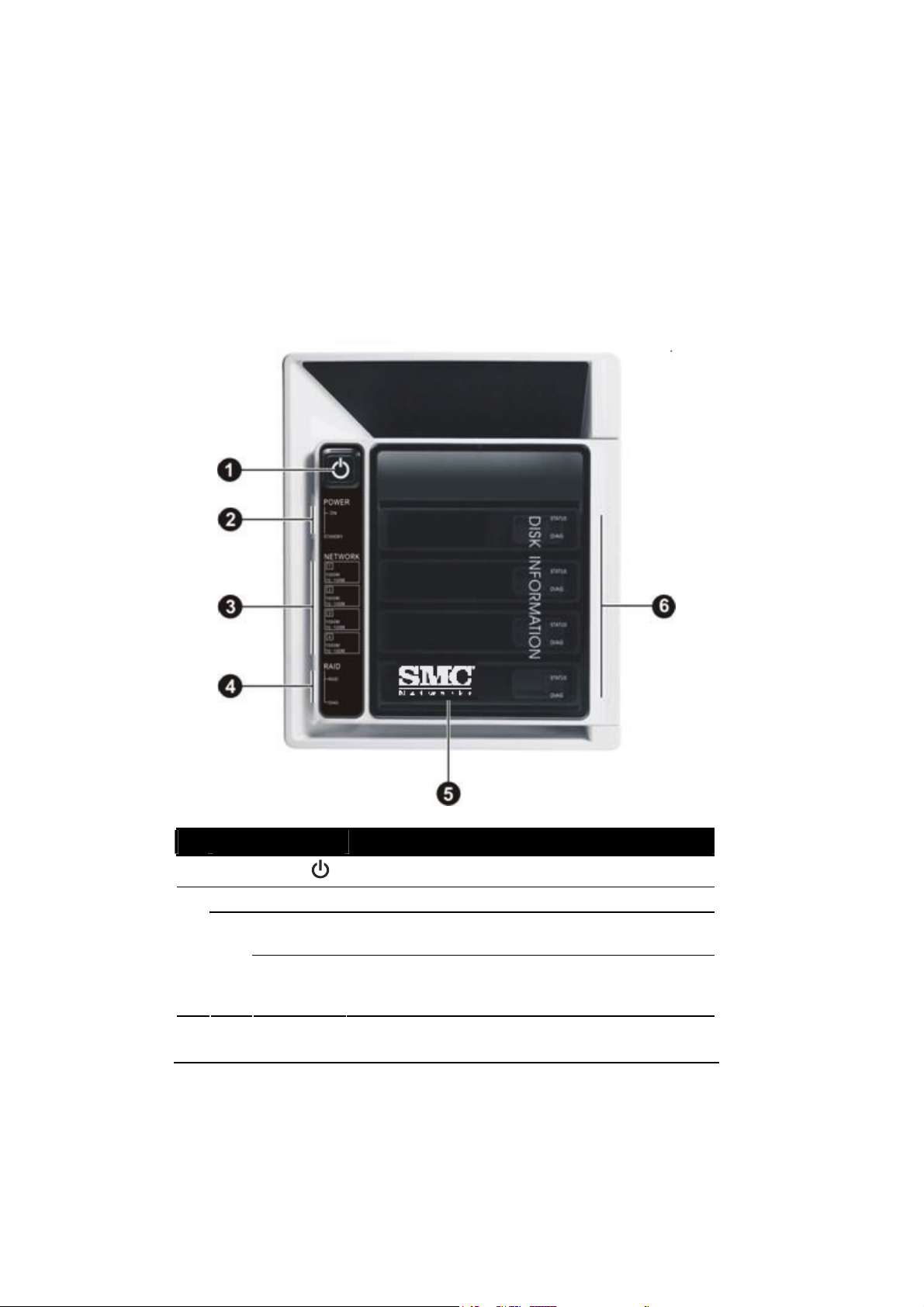
1.3 System View
Front Components
Ref Component Description
Power Button
n
Power Indicator
o
POWER
ON
STANDBY
Turns the power on and off.
Shows the current power status.
Glows blue when the power is on.
Glows red when the system is in Standby mode
(power cord is connected to the outlet but storage system
is at standby situation).
4
Page 14

Ref Component Description
Network Indicator
p
RAID Indicator
q
Hard Disk Drive
r
Compartment
Disk Information
s
Indicator
RAID
DIAG
STATUS
DIAG
Shows the current network status.
Glows green at 10/100 Mbps or blue at 1000 Mbps when
system is connected to the network.
Blinks green or blue to indicate system is trying to
establish a network connection.
Shows the current RAID status.
Glows blue to indicate RAID function is implemented.
Blinks blue to indicate RAID function is rebuilding the
hard disk drive.
Glows red to indicate RAID function is inactive or
malfunctioning.
Contains four hard disk drive slots.
Shows the current hard disk drive status.
Glows blue to indicate hard disk drive/s is standby.
Blinks blue to indicate hard disk drive/s read/write
function.
Glows red to indicate hard disk drive is inactive or
malfunctioning.
5
Page 15
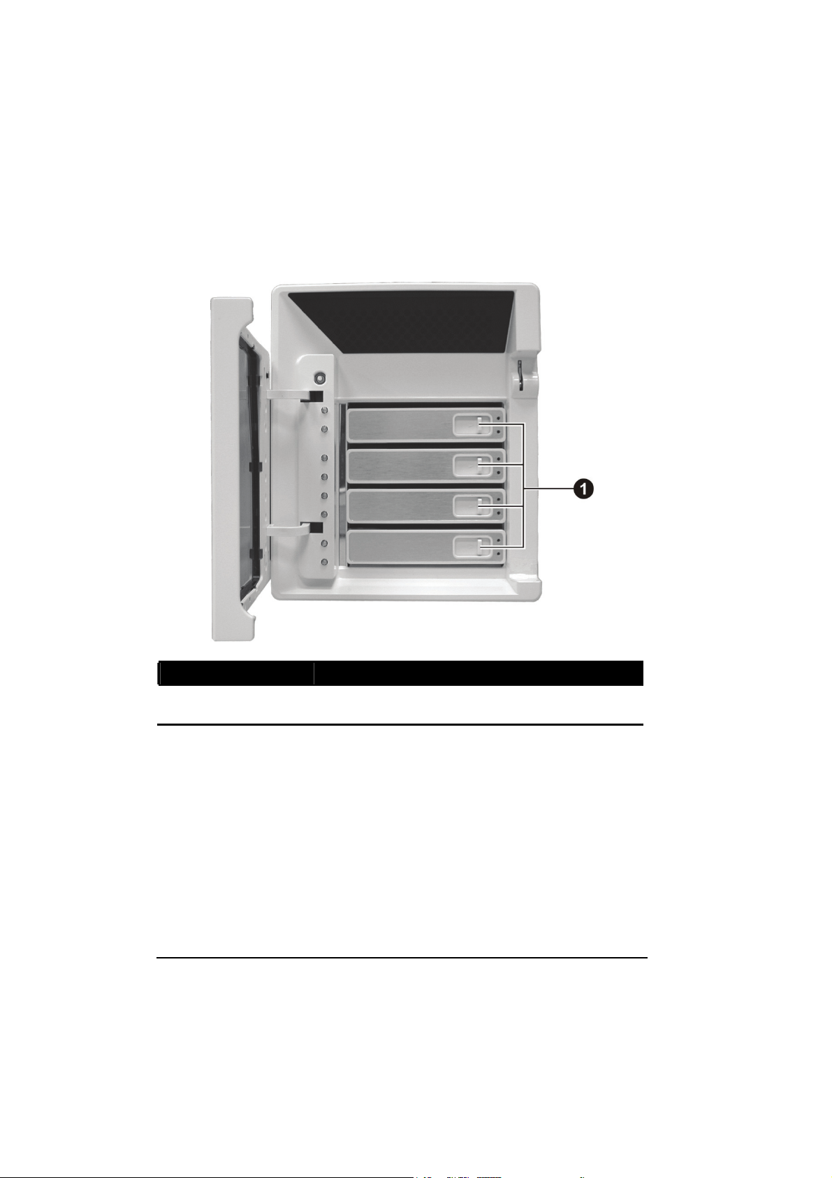
Front Components (Compartment Door Open)
Ref Component Description
Hard Disk Tray
n
Door Handle
Opens the hard disk tray.
6
Page 16
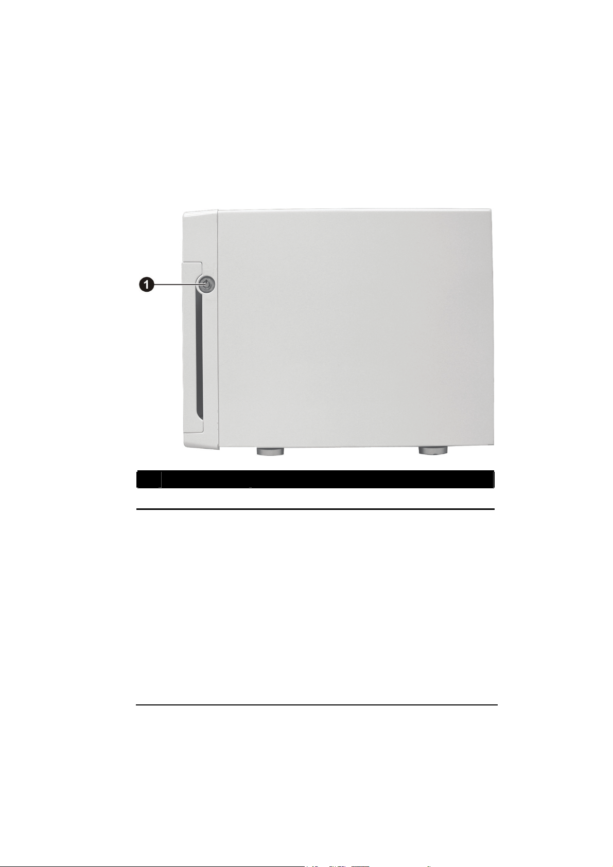
Right-Side Components
Ref Component Description
n
Door Lock
Locks the hard disk drive compartment door for security.
7
Page 17
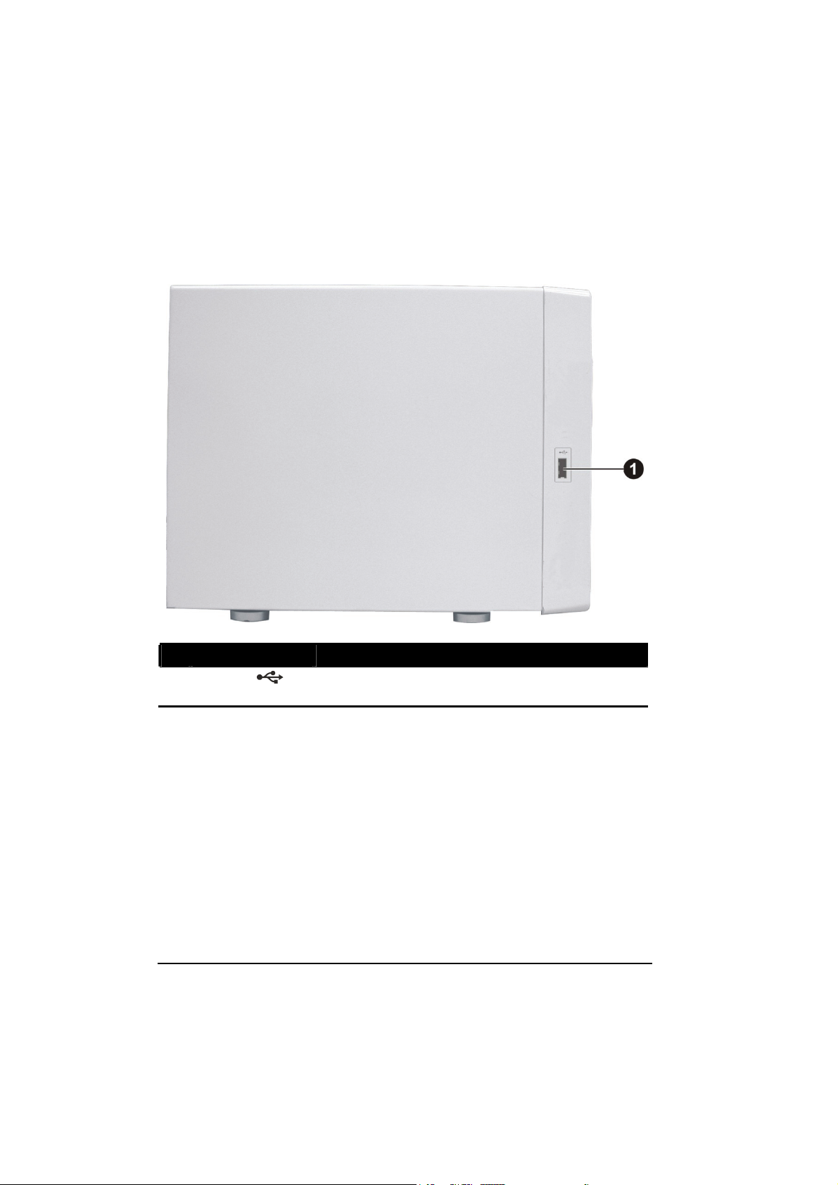
Left-Side Components
Ref Component Description
USB Port
n
Connects a USB device, such as a USB disk, printer, or
USB-UPS.
8
Page 18
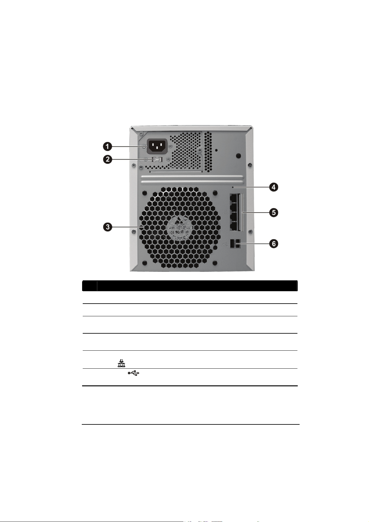
Rear Components
Ref Component Description
Power Connector
n
Voltage Switch
o
Ventilation
p
Opening
Reset Switch
q
RJ-45 Connectors
r
0/1/2/3
USB Ports
s
Connects to the power cord.
Select the voltage matching your local standard setting.
Maintain proper operating temperature. Do not cover or
block the openings.
Allows you to reset the system to the factory default
username, password, and HDCP
Connects the LAN cable to any of the four connectors.
Connects USB devices, such as a USB disk, printer,
and/or USB-UPS.
9
Page 19
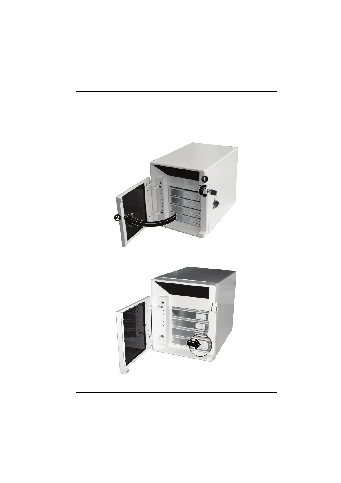
Chapter 2 Setting Up
Step 1. Install the Hard Disks
1. Insert the key and turn clockwise (n) to unlock and open the door (o).
2. Slide the latch toward the right to release the handle.
11
Page 20
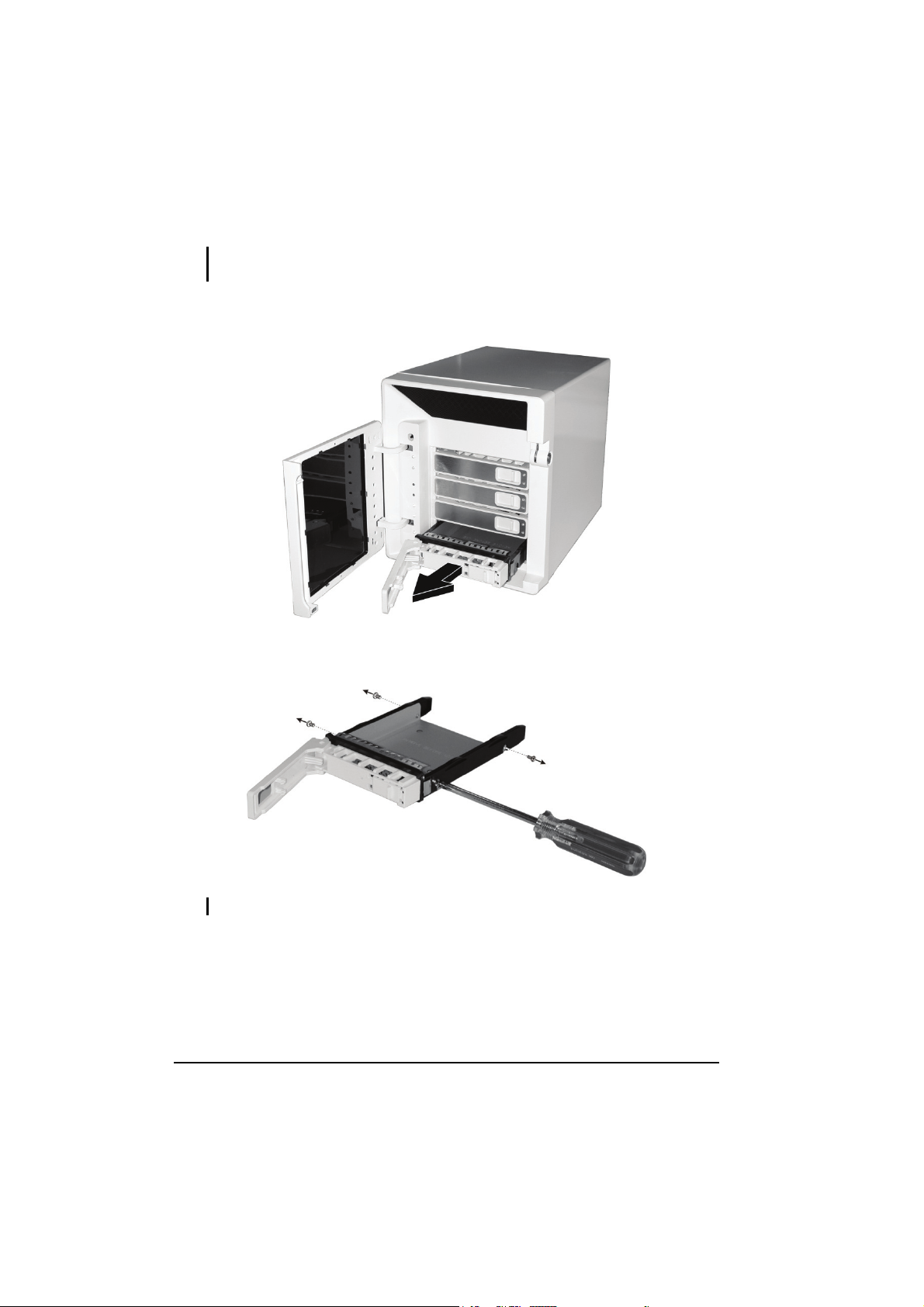
NOTE: Install the first hard disk on the lowest level tray first, the second hard disk on the
second lowest level tray, and so forth.
3. Pull the handle to slide the hard disk tray forward. Then, pull the hard disk
tray out of the device.
4. Unfasten four screws from each side of the hard disk tray and remove the
metal bracket.
NOTE: Store the metal bracket well in a safe place for future use.
12
Page 21
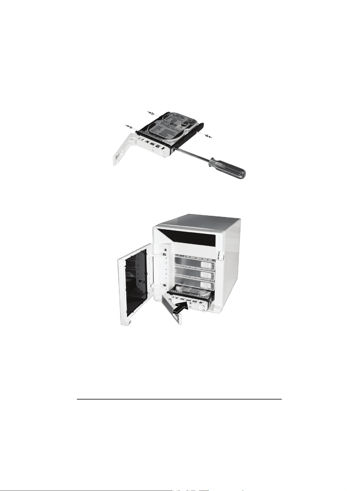
5. Fit the hard disk into the tray where the connectors facing toward the rear.
Then align and fasten four screws for fixing the hard disk in the tray.
6. Keeping the handle in its full-open state, slide the hard disk tray all the way
into the device until the hinge of the handle is inside the device. Then, close
the handle. The latch should be clicked into place.
7. Repeat the procedures above for installing another hard disk(s) in the other
compartment(s).
13
Page 22
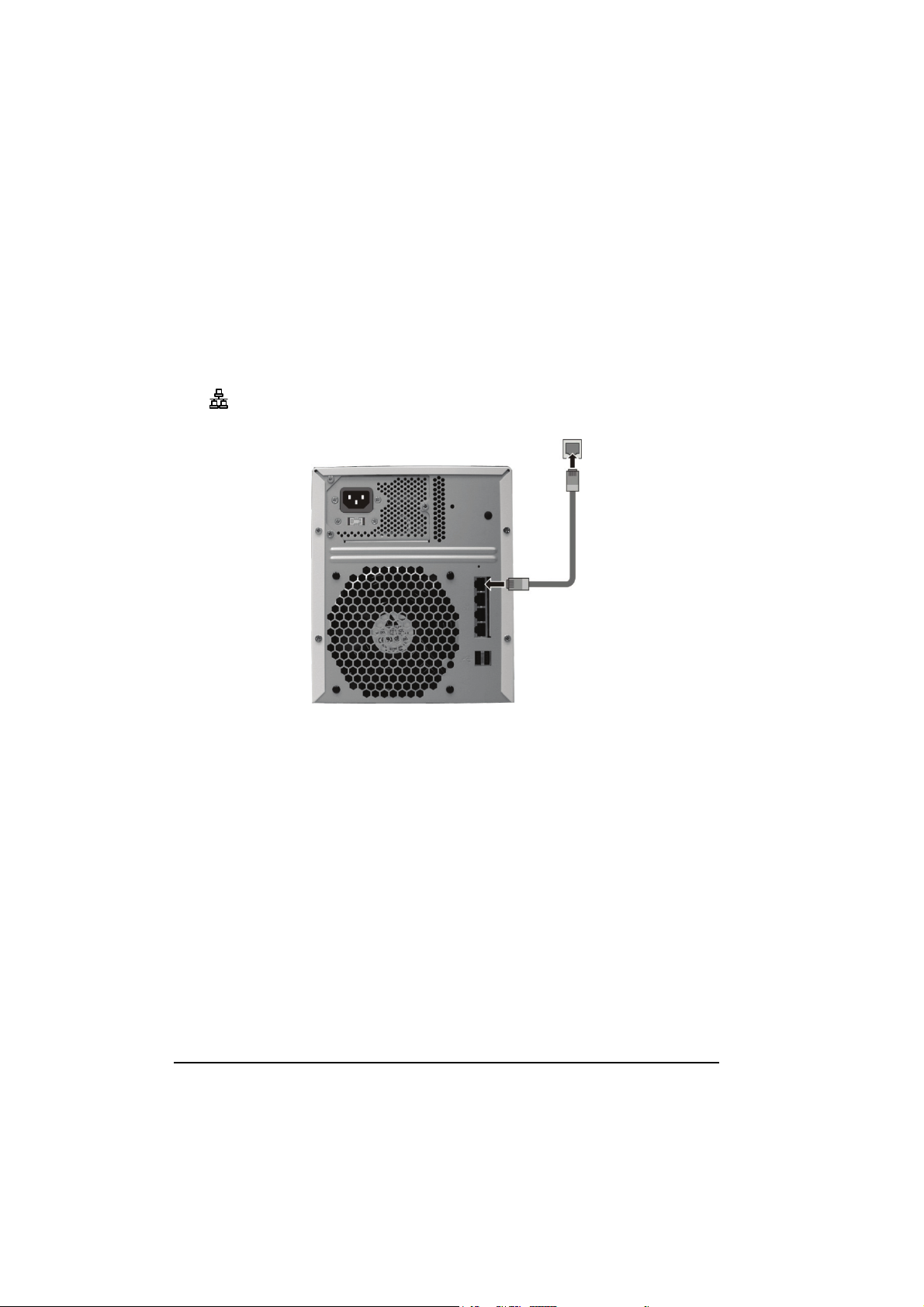
Step 2. Connect to the Network
1. Make sure that the computer, which you will install and perform Storage
System Management, is powered off and connected to the network hub.
2. Make sure that the network hub is powered off.
3. Connect one end of the Ethernet cable to any of the four network connector
) on the back of your storage system and the other end to the network
(
hub.
14
Page 23
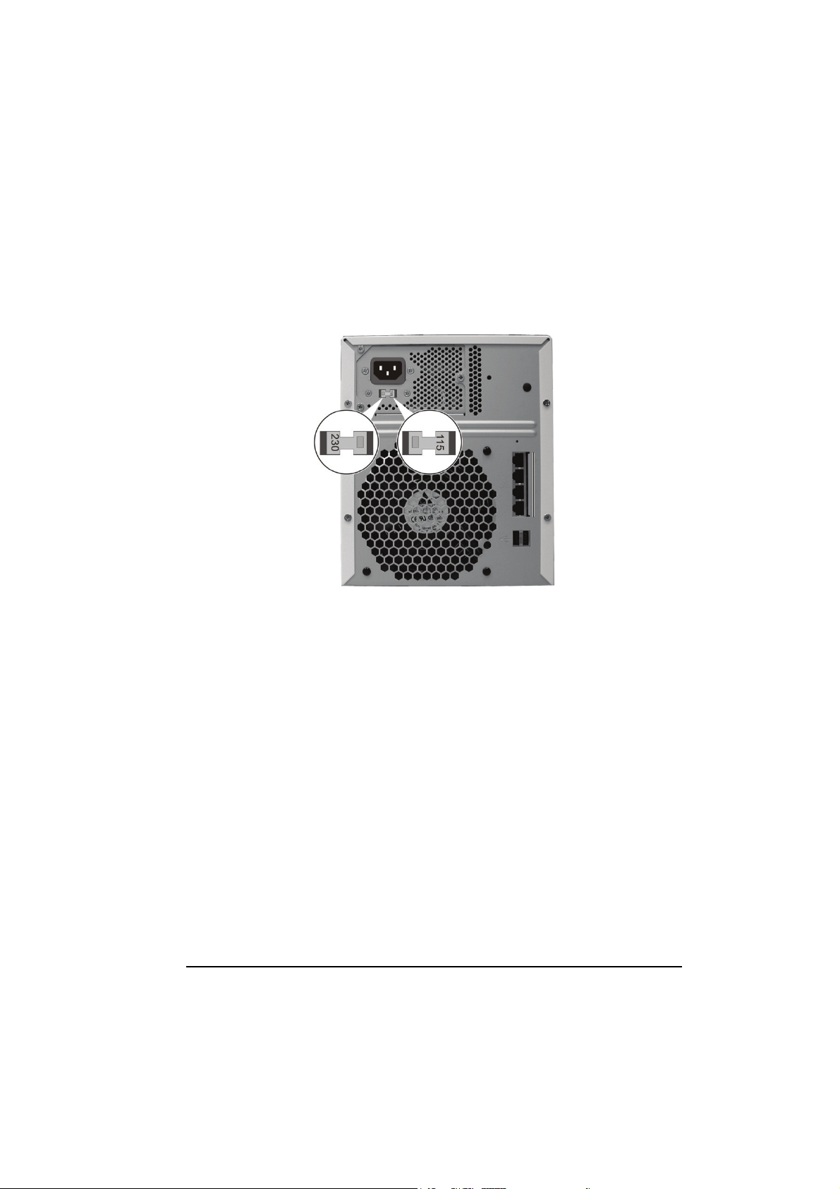
Step 3. Connect to Power
1. Make sure that your storage system is turned off.
2. Before connecting to power, set the Voltage Switch to the voltage matching
your local standard setting.
15
Page 24
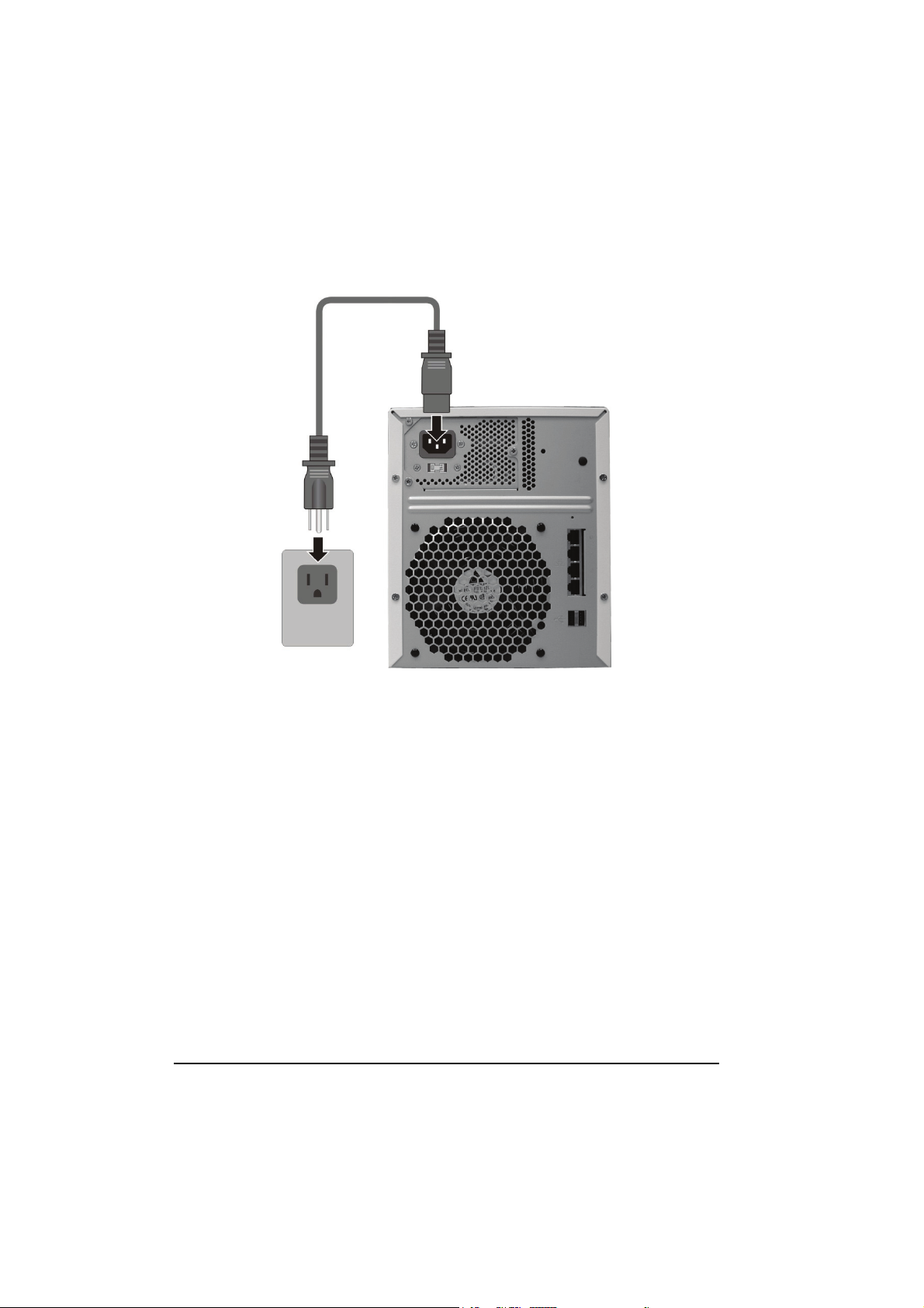
3. Connect one end of the power cord to your storage system and the other end
to a standard electrical outlet.
4. Power on your network hub.
5. Power on your computer.
Step 4. Configure Your Storage System
See the next chapter for software configuration instructions.
16
Page 25

Chapter 3 Configuring Your Storage System
You have to install at least one hard disk (lowest level tray) before your storage
system can provide services.
SMCNAS04
SMCNAS24
A network consists of your storage device, computer for Storage System
Management, and several clients connected via network links.
17
Page 26

3.1 Installing the Storage System Management
You need to install Storage System Management before you can perform any
system configurations.
NOTE: Make sure that your storage device is powered off.
1. Copy the contents of the Utility disc to your computer.
2. Double-click “jre-6-windows-i586.exe” to install JAVA Runtime
Environment (JRE) 6 on your computer. Click on the link to download thru
your browser
http://java.sun.com/javase/downloads/index.jsp
3. Double-click
“x:\NASDiscoveryUtility\NASDiscovery.html” (where “x”
is the drive that you have copied NASDiscoveryUtility on your computer).
The following screen appears.
18
Page 27

4. Press the Reset switch (n) by inserting a small rod such as straightened
paperclip and press the Power button (o) on your storage device at the same
time. You can only release the Reset switch after the blue RAID indicator
(
) blinks (may take 15~20 seconds).
5. Wait for a while (approximately 3~5 minutes) until the following screen
appears. Click “Click to Configure RAID Profile” under the
“Configuration URL” column.
19
Page 28

6. The following screen appears. Change the RAID configuration by clicking
the radio button of the available RAID configuration on the “CHANGE TO”
column under “RAID Profiles,” then click “CHANGE.”
20
Page 29

7. The following screen appears.
21
Page 30

8. Double-click
“x:\NASDiscoveryUtility\NASDiscovery.html” again and
the following screen appears. Wait for approximately five minutes.
9. When the following screen appears, click “Click to Upgrade” under the
“Upgrade” column. It will show “Will start soon” to signify the start of the
upgrade process.
22
Page 31

10. The “Upgrade” column will show various stages of the upgrade process:
z Upload % Done
z Verifying Checksum
z Extracting Firmware
z Installing OS
z Installing Kernel
z Installing Media Server
z Installing KHTTPD
z Installing Samba
z Installing Configurator
z Installing NASUtils
11. When the upgrade process is done, the following screen appears and the
“Upgrade” column would show “Upgrade Done: Rebooting.”
23
Page 32

12. When the following screen appears, click “Click to Configure NAS” under
the “Configuration URL” column to log in Storage System Management.
Proceed to the next section on performing Storage System Management.
NOTE: About the function of “Click to Map” under the “MAP Shares” column, please refer
to “Chapter 4 MAP SHARES.”
24
Page 33

3.2 Starting Storage System Management
NOTE: Click the “x:\NASDiscoveryUtility\NASDiscovery.html”
(where “x” is the drive that you have copied NASDiscoveryUtility on your computer), when
the following screen appears, click “Click to Configure NAS” under the “Configuration
URL” column to log in the Storage System Management.
25
Page 34

To perform system management using the Storage System Management:
1. As soon as you start Storage System Management, the system automatically
scans the network for storage systems. This might take a few minutes. The
following screen appears.
2. Enter the default User name “admin” and the default Password “smcadmin”
then select the desired language.
3. Click “Log In.” The Storage System Management homepage, contains six
tabs namely, My NAS, Users & Groups, Shared Folders, Disk, Advanced, and
Logout, would appear.
26
Page 35

3.3 My NAS Page
Display a list of your storage system information (MNAS name, flash and
middleware version, MAC and IP address, subnet mask, gateway IP address,
and disk mode) , system utilization , data utilization, and current connections
(shared folders, users, and login time).
System utilization: show current system data partition usage
Data utilization: show current the data partition usage
27
Page 36

System Setting
Allow you to specify the storage system name, date, time, time zone, NTP
server name or IP address, administrator name, and password.
On the “My NAS” page, click “System setting” and the following screen appears.
NOTE: Be careful when changing the “Storage System Name.” Inform your clients of any
change of this column for providing available functions, including shared folders or
backups.
28
Page 37

To change this . . . Do this . . .
Storage system name
Date, Time, Time zone
NTP server name or IP
address
Administrator name
Password
Confirm password
Enter the new name for the specific storage
system. The name can be up to 15 characters
long, including characters of letters, numbers,
and hyphens.
In the Date fields, enter or select the month,
day, and year.
In the Time fields, enter or select the hour,
minute, and second.
Use the Time zone drop-down bar to select the
time zone.
Enter the name or IP address of the Network
Time Protocol server from which the storage
system should adjust its time. You can use an
NTP server name only if it is resolvable/
recognizable.
In the Administrator name field, enter the
administrator name for logging in to the
Storage System Management.
In the Password and Confirm password fields,
enter the password for logging in to the Storage
System Management. The administrator name
and password are case-sensitive.
1. After making the necessary changes, click “Apply.”
2. When the message of confirmation appears, click “OK” for the changes to
take effect.
29
Page 38

Network Setting
Allow you to configure the network settings that include the workgroup name,
MAC address, and FTP server settings.
1. Click “Network setting” and the following screen would appear.
30
Page 39

To change this . . . Do this . . .
Workgroup name
Get an IP address
automatically
Use this IP address
IP address
Subnet mask
Enable FTP server
Enter the new name for the specific workgroup.
The name can be up to 15 characters long,
including characters of letters, numbers, and
hyphens.
If you have a DHCP server on your network, the
server can get its IP address from that DHCP
server automatically.
If you do not have a DHCP server, you have to
specify an IP address, subnet mask, gateway IP
address, and DNS server.
Allow your storage device to perform as an FTP
server, and suggests to download data transfer tool
at
http://filezilla.sourceforge.net/
2. After making the necessary changes, click “Apply.”
3. When the message of confirmation appears, click “OK” for the changes to
take effect.
REMINDER: If you are using Filezilla as your FTP data transfer tool, please follow the
setting NOT to enable the function of “Use multiple connections to transfer files”, or if you
are not using Filezilla, please also refer to the setting.
31
Page 40

3.4 Users & Groups Page
Display a list of all currently configured users for allowing you to add, modify,
and remove users. This area also allows you to add, modify, and remove groups
as well as perform quota management.
Users
1. Click the “Users & Groups” button on the Storage System Management
homepage. The following screen appears.
2. Add the users. After the user is added, you can assign the user to shared
folders by clicking “Shared Folders” to assign/restrict access (see later
section for details).
NOTE: Windows users can be joined into groups as well as assign several users to a
shared folder.
32
Page 41

3. Click “Add” and the following screen appear, allowing you to specify the
type of user (Windows/Mac OS X or Linux/Other Mac – future option) you
want to add.
33
Page 42

4. Click “Next” and the following screen appears. You must provide the
requested user information.
For Windows/Mac OS X user (CIFS) –
To change this . . . Do this . . .
User name
Password
Confirm password
34
In the User name field, enter the user name.
In the Password and Confirm password fields,
enter the password for accessing any shared
folders.
Page 43

For Linux/other Mac user (NFS) – (future option)
To change this . . . Do this . . .
Computer description
IP address or computer
name
The Computer description field can be the name
of the user who typically accesses the computer
or any other description to identify the
computer.
The IP address or computer name field
identifies the Host system, enter the IP address
or computer name of the user you are adding.
5. Click “Apply” and the new user would be added. Repeat the above steps
until you have added all the users that you want to add at this time.
35
Page 44

Groups
Placing users into groups makes it easier to give several users access to the same
shared folder at once.
1. Click “Groups” on the “Users & Groups” page. The following screen
appears.
NOTE: Only Windows users can be included in groups.
36
Page 45

2. Click “Add” and the following screen appear. Enter a group name and add
all or selected users to this group.
You can also remove all or selected users from a group.
3. Click “Apply.”
37
Page 46

Quota Management
Allows the administrator to limit (enlarge/shrink) user disk space.
NOTE: Before enabling/disabling Quota Management, make sure that iTunes is not
enabled, no USB device is mounted, and there is no existing Samba connection to your
storage device (see later section for details).
1. Click “Quota management” on the “Users & Groups” page. The following
screen appears.
38
Page 47

To change this . . . Do this . . .
Enable quota for all users
Quota size on the SATA disk
Administrator password
Users
Set the Quota Size of guest
on the SATA disk
Administrator password
Click the checkbox to set quota for all
Windows users.
In the Quota size on the SATA disk field, enter
the quota size (MB).
In the Administrator password field, enter the
password for logging in to the Storage System
Management. The password is case-sensitive.
Displays a list of available users.
It is for the set quota of the specific user on the
SATA disk field, select No Limit or Quota Size
and enters the quota size (MB).
In the Administrator password field, enter the
password for logging in to the Storage System
Management. The password is case-sensitive.
2. After making the necessary changes, click the upper “Apply” for all users
and select one specific user in the lower and set his/her quota to “No limit”
or “quota size,” key in the Administrator password and “Apply.”
3. When the message of confirmation appears, click “OK” for the changes to
take effect.
39
Page 48

3.5 Shared Folders Page
Display a list of all currently configured and shared folders and allow you to add
shared folders, change which users can access them, or remove them.
1. Click the “Shared Folders” button on the Storage System Management
homepage. The following screen appears.
40
Page 49

Add Shared Folder
1. Click “Add” to create shared folder and the following screen appears.
2. Enter the name of the new shared folder and click “Next.”
3. Select the users/groups who you want to authorize (add or remove user).
4. Click “Apply.”
41
Page 50

Assign Access
1. Select a folder which you want to modify. Click “Assign Access” and the
following screen appear.
2. Enter the “Shared folder name.”
3. You can “Add” (specify as “Read-Only” or “Read/Write”) users/groups to, as
well as “Remove” existing users/groups from shared folders.
4. Click “Apply.”
42
Page 51

5. When the message of confirmation appears, click “OK” for the changes to
take effect.
3.6 Disk Page
Allow you to view information about the installed hard disk(s) slot, model,
serial number, size, RAID type, and disk status (shows the RAID rebuilding
percentage).
43
Page 52

3.7 Advanced Page
Provide access to advanced storage system configuration options such as setting
up email alerts; upgrading the firmware; UPS (uninterruptible power supply),
iTunes/media/printer server, USB backup; viewing information about system
events; and shutting down, reboot, back to zero disk the system remotely
44
Page 53

Alerts
Allow you to set up the storage system to notify up to two people via email if
any problem occurs namely, when hard disk space usage have reached one
limitation of total capacity, when the upper operating temperature has been
reached, and when power level of the USB-UPS is not adequate .
To have a good use of this feature, you must have to access an SMTP email
server, either within your own network or through an Internet service provider.
NOTE: In order to be able to send out email alerts, the “Authentication” feature of the
intended email recipient must be disabled.
45
Page 54

1. Click on the “Advanced” button on the Storage System Management
homepage. The following screen appears.
2. Enter the information about your SMTP email server, sender’s email
address, and up to two email addresses that should receive the notification.
NOTE: If your SMTP email server has authenticated, enable it and enter the User name
and Password.
3. Click “Apply.”
46
Page 55

4. When the message of confirmation appears, click “OK” to confirm.
Firmware
Allows you to upgrade your storage system to a newer firmware when available
(check the support section of
1. Click “Firmware” on the “Advanced” page and the following screen appears.
For additional security, you must enter your administrator password in
order to upgrade the firmware.
www.smc.com for the latest firmware).
2. Click “Browse” and select the firmware file
Upgrade-x.x.x.xxxx-Vxx.xx.cpio.bz2 (example as D:\
Upgrade-2.7.0.0309-V1.0.cpio.bz2) from the displayed list.
(you can place the
folder on your PC that you like)
Upgrade_ x.x.x.xxxx-Vxx.xx.cpio.bz2 in any
3. In the “Administrator password” text box, enter the password.
47
Page 56

4. Click “Apply.”
5. When the message of confirmation appears, click “OK” to confirm.
6. The upload percentage will be displayed.
7. System will reboot automatically after upgrade is done.
48
Page 57

iTunes Server
Allow your storage system to function as an iTunes server for accessing digital
music and video files from an iTunes client computer.
1. Click “iTunes Server” on the “Advanced” page and the following screen
appears.
2. Click the checkbox “iTunes Server enabled.”
49
Page 58

Media Server
Allow your storage system to function as a media server by specifying the scan
path, selecting the media file type(s), start scanning and afterwards display the
results of the scan, as well as delete and backup media database.
1. Click “Media Server” on the “Advanced” page and the following screen
appears.
50
Page 59

To change this . . . Do this . . .
Change Scan Paths
Media Scan Types
Media Scan Control
Media Scan Details
(Previous Scan)
Delete Database
Click Change Scan Paths if you want your
computer to search for media files which differ
from the one currently specified (see step 2).
Click on the checkbox of the file types on the
list to be included, and then click Set Types.
Click Start Scan to start scanning.
Displays the result of the latest scan by showing
the total number of image files, audio files,
video files, rejected files, and scan time.
1. The total number of media items would be
displayed.
2. Delete database:
It will delete the playlist.
2. Upon clicking “Change Scan Paths” the following screen would appear.
3. Select the desired scan path(s).
51
Page 60

4. Click “Apply.”
5. When the message of confirmation appears, click “OK” to confirm.
Printer Server
Allow your storage system to function as a printer server when a USB printer is
connected.
1. Connect a printer to any USB port on your storage system.
2. Click “Printer Server” on the “Advanced” page and the following screen
appears.
NOTE: To be able to print Postscript file, you need to convert it to PDF format first.
3. Click the checkbox “Printer Server enabled.”
4. Click “Apply.”
52
Page 61

NOTE: A warning message will appear if there is no USB printer connected to your storage
system.
5. When the message of confirmation appears, click “OK” to confirm.
NOTE: When setting up the USB printer on your computer, you need to specify the storage
system’s IP:631/printers/PrinterServer.
UPS (Uninterruptible Power Supply)
Allow your storage system to use a USB-UPS as temporary backup power.
1. Connect a USB-UPS to any USB port on your storage system.
NOTE: When using the USB-UPS and the power level is not adequate, an email alert will
be sent for informing you to shutdown the storage system immediately.
2. Click “UPS” on the “Advanced” page and the following screen appears.
53
Page 62

3. Click the checkbox “UPS enabled.” The “Power status” (amount of backup
power available) will be shown.
4. Click “Apply.”
NOTE: A warning message will appear if there is no USB-UPS connected to your storage
system.
5. When the message of confirmation appears, click “OK” to confirm.
54
Page 63

USB Backup
Allow you to backup the contents of your USB storage device to your storage
system.
1. Click “USB backup” on the “Advanced” page and the following screen
appears.
2. In the “Administrator password” text box, enter the password.
3. Click “Apply.”
4. If you want to change the default “Criteria of backup available space,” in the
“Criteria of backup available space” textbox, enter the value (MB) to change
the allocated disk space allowed for backing up to your storage system.
Otherwise do not change it, the default setting of the criteria of backup
available space (10 %) is suggested.
5. Enter the password again.
55
Page 64

6. Click “Apply.” The backup contents of your USB storage device would be
copied to your storage system on a newly created timestamp folder under
/USBBackup/.
NOTE: When the total file size overflows the limitation, the warning message “The disk
space is not enough” appears.
System Log
Display a list of events that have occurred on the storage system. Reviewing this
list can help you identify and resolve any problems that you might encounter.
1. Click “System log” on the “Advanced” page and the following screen
appears. The date and time of the event, the type of event (I stands for
informational, E stands for error, W stands for warning, and C stands for
critical error), and a brief description of the event are displayed.
2. If an event occurs while you are viewing this list, click “Refresh” to update
it.
56
Page 65

Shut Down
To shut down the storage system, you can press the power button on the unit
itself and hold it until the system status and disk activity LEDs start flashing, or
you can shut the storage system down remotely by using Storage System
Management. To use Storage System Management:
1. Click “Shut Down” on the “Advanced” page and the following screen
appears, allowing you to shutdown the storage system.
CAUTION: Make sure no one is backing up a disk or using a shared folder before you shut
down the storage system.
2. Enter the “Administrator password.”
57
Page 66

3. Click “Shut Down.” A message appears the indication of that the system is
shutting down.
CAUTION: Always shutdown the system in accordance with the instructions above. An
improper shutdown may affect the functionality of storage system in the next startup.
58
Page 67

Reboot
You can reboot the storage system remotely by using Storage System
Management. To use Storage System Management:
1. Click “Reboot” on the “Advanced” page and the following screen appears,
allowing you to reboot the storage system.
CAUTION: Make sure no one is backing up a disk or using a shared folder before you
reboot the storage system.
2. Enter the “Administrator password.”
59
Page 68

3. Click “Reboot.” A message appears the indication of that the system is
rebooting.
CAUTION: Always reboot the system in accordance with the instructions above. An
improper reboot may affect the functionality of storage system in the next startup.
60
Page 69

Back to Zero Disk
User does not need to press hardware “reset” button 15 seconds to go back to
zero disk again. User can click the “Back to Zero Disk” of “Advanced” page.
1. Click “Back to Zero Disk” on the “Advanced” page and the following screen
appears, allowing you to back to software installation step 3.1.5. to change
the preferred RAID configuration.
2. Enter the “Administrator password.”
61
Page 70

3. Click “Back to Zero Disk.” A message appears indicating that the system is
rebooting.
4. Wait for a while (approximately 3~5 minutes) until the following screen
appears. Click “Click to Configure RAID Profile” on the “Configuration
URL” column (Please refer to software installation STEP 3.1.5.)
5. The following screen appears. Select the preferred RAID configuration by
clicking the “CHANGE TO” drop down menu under “RAID Profiles,” then
click “CHANGE” (Please refer to software installation step 3.1.6.)
CAUTION: An improper reboot may affect the functionality of storage system in the next
startup.
62
Page 71

3.8 Logging Out of Storage System Management
1. To log out of the Storage System Management system without shutting it
down, click the “Logout” button.
63
Page 72

2. When the message of confirmation appears, click “OK”.
3. The following screen appears. You can allow it to stay in the background
and perform other computer task. To use the Storage System Management
later, click “Log In.”
64
Page 73

Chapter 4 MAP SHARES
1. The following screen appears, click “Click to Map” under the “MAP Shares”
column to map shared folders.
2. Then, the following screen appears.
NAS Samba Share: User could select which shared folder to connect.
Share Name: User could re-name a preferred share name.
65
Page 74

Input Limitation
Before the user inputs are set to the system, the WEB GUI is required to validate
the user inputs according to the following rules:
Administrator name:
9 Maximum number of characters: 15
9 Rules: Can include only letters (uppercase and lowercase A-Z),
numbers (0-9), hyphens (-), underlines (_), and dots (.). First
character must be a letter (uppercase and lowercase A-Z)
Administrator password:
9 Maximum number of characters: 8
9 Rules: Any printable ASCII characters but not [ ' ]
Host name: *
9 Maximum number of characters: 15
9 Rules: Can include only letters (uppercase and lowercase A-Z),
numbers (0-9) and hyphens (-).First character must be a letter
(uppercase and lowercase A-Z)
9 Because the iSCSI target name need use to add the original hostname
with the underline.
66
Page 75

Workgroup name: *
9 Maximum number of characters: 15
9 Rules: can include only letters (uppercase and lowercase A-Z),
numbers (0-9), hyphens (-) and underlines (_). First character must
be a letter (uppercase and lowercase A-Z)
CIFS user name:
9 Maximum number of characters: 15
9 Rules: Can include only letters (uppercase and lowercase A-Z),
numbers (0-9), hyphens (-), underlines (_) and dots (.). First
character must be a letter (uppercase and lowercase A-Z),
9 User name cannot be uppercase and lowercase “root,” “backupuser,”
“nobody,” “ftp,” “anonymous.”
CIFS group name:
9 Maximum number of characters: 15
9 Rules: Can include only letters (uppercase and lowercase A-Z),
numbers (0-9), hyphens (-), underlines (_) and dots (.). First
character must be a letter (uppercase and lowercase A-Z).
9 Group name cannot be uppercase and lowercase “root,” “isadmin,”
“isclient,” “isrou,” “isbmr,” “nasgrp.”
NFS computer description:
9 Maximum number of characters: 15
9 Rules: Can include only letters (uppercase and lowercase A-Z),
numbers (0-9), hyphens (-), underlines (_) and dots (.). First
character must be a letter (uppercase and lowercase A-Z).
67
Page 76

NFS computer name (IP or domain name):
9 Maximum number of characters: 64
9 Rules: Can include only letters (uppercase and lowercase A-Z),
numbers (0-9), hyphens (-), underlines (_), dots (.), slash(/), star(*),
question mark (?).
Shared name:
9 Maximum number of characters: 64
9 Rules: Can include only letters (uppercase and lowercase A-Z),
numbers (0-9), hyphens (-), underlines (_) and dots (.). First
character must be a letter (uppercase and lowercase A-Z).
9 Share name cannot be uppercase and lowercase “com1” … “com9”,
“lpt1” … “lpt9,” “con,” “nul,” “prn,” “aux,” “homes,” “spool,”
“usbdisk1,” “usbdisk2,” “usbprint1,” “usbprint2.”
SMTP server name:
9 Maximum number of characters: 64
9 Rules: Can include only letters (uppercase and lowercase A-Z),
numbers (0-9), hyphens (-), underlines (_) and dots (.)
Email address:
9 Maximum number of characters: 128
68
Page 77

IP, subnet mask, Gateway, DNS address:
9 Maximum number of characters: 15 (3 “.” included)
9 Rules: The format is xxx.xxx.xxx.xxx and the value of xxx is
between 0 and 255
NTP server name:
9 Maximum number of characters: 64
9 Rules: Can include only letters (uppercase and lowercase A-Z),
numbers (0-9), hyphens (-), underlines (_) and dots (.)
SMTP user name:
9 Maximum number of characters: 64
9 Rules: Cannot include quote (‘), double-quote (“), backslash (\),
question mark (?), (&), angle brackets (<) and (>).
69
Page 78

TECHNICAL SUPPORT
From U.S.A. and Canada (24 hours a day, 7 days a week)
Phn: 800-SMC-4-YOU / 949-679-8000
Fax: 949-502-3400
ENGLISH
Technical Support information available at www.smc.com
FRENCH
Informations Support Technique sur www.smc.com
DEUTSCH
Technischer Support und weitere Information unter www.smc.com
SPANISH
En www.smc.com Ud. podrá encontrar la información relativa a
servicios de soporte técnico
DUTCH
Technische ondersteuningsinformatie beschikbaar op www.smc.com
PORTUGUES
Informações sobre Suporte Técnico em www.smc.com
SWEDISH
Information om Teknisk Support fi nns tillgängligt på www.smc.com
SMCNAS04/
SMCNAS24
INTERNET
E-mail address: techsupport@smc.com
Driver updates
http://www.smc.com/index.cfm?action=tech_support_drivers_downloads
World Wide Web
http://www.smc.com/
20 Mason • Irvine, CA 92618 • Phn: 949-679-8000 • www.smc.com
 Loading...