

Page 1

SMCGS18/26/50C-Smart
SMCGS18/26/50P-Smart
Page 2

Web Smart 18/26/50-Port GE Switch
Web Smart 18/26/50-Port GE PoE Switch
Management Guide
No. 1, Creation Road III,
Hsinchu Science Park,
30077, Taiwan, R.O.C.
TEL: +886 3 5638888
Fax: +886 3 6686111
March 2014
E032014-CS-R03
Page 3

Information furnished by SMC Networks, Inc. (SMC) is believed to be accurate and reliable.
However, no responsibility is assumed by SMC for its use, nor for any infringements of patents or
other rights of third parties which may result from its use. No license is granted by implication or
otherwise under any patent or patent rights of SMC. SMC reserves the right to change specifications
at any time without notice.
Copyright © 2014 by
SMC Networks, Inc.
No. 1 Creation Road III,
Hsinchu Science Park,
30077, Taiwan, R.O.C.
All rights reserved
Trade m ar k s :
SMC is a registered trademark; and Barricade, EZ Switch, TigerStack, TigerSwitch, and TigerAccess
are trademarks of SMC Networks, Inc. Other product and company names are trademarks or
registered trademarks of their respective holders.
Page 4

WARRANTY AND PRODUCT REGISTRATION
To register SMC products and to review the detailed warranty statement,
please refer to the Support Section of the SMC Web site at http://
www.smc.com.
– 4 –
Page 5

ABOUT THIS GUIDE
PURPOSE This guide gives specific information on how to operate and use the
management functions of the switch.
AUDIENCE The guide is intended for use by network administrators who are
responsible for operating and maintaining network equipment;
consequently, it assumes a basic working knowledge of general switch
functions, the Internet Protocol (IP), and Simple Network Management
Protocol (SNMP).
CONVENTIONS The following conventions are used throughout this guide to show
information:
N
OTE
:
Emphasizes important information or calls your attention to related
features or instructions.
C
AUTION
damage the system or equipment.
W
ARNING
:
Alerts you to a potential hazard that could cause loss of data, or
:
Alerts you to a potential hazard that could cause personal injury.
RELATED PUBLICATIONS The following publication details the hardware features of the switch,
including the physical and performance-related characteristics, and how to
install the switch:
The Installation Guide
Also, as part of the switch’s software, there is an online web-based help
that describes all management related features.
REVISION HISTORY This section summarizes the changes in each revision of this guide.
MARCH 2014 REVISION
This is the third version of this guide. This guide is valid for software
release v1.0.0.4. It includes the following changes:
◆ Correction to information on restoring factory defaults (see "System
Defaults" on page 28).
– 5 –
Page 6

A
BOUT THIS GUIDE
◆ Update on retaining IP settings when restoring factory defaults (see
"Restoring Factory Defaults" on page 290).
MARCH 2013 REVISION
This is the second version of this guide. This guide is valid for software
release v1.0.0.4. It includes information on the following changes:
◆ The VeriPHY option was removed from the Diagnostices menu.
◆ IGMP SSM Range was added to the Advanced Configuration, IPMC,
IGMP Snooping, Basic Configuration menu (see "Configuring Global and
Port-Related Settings for IGMP Snooping" on page 146).
◆ Compatibility was added to the Advanced Configuration, IPMC, IGMP
Snooping, VLAN Configuration menu (see "Configuring VLAN Settings
for IGMP Snooping and Query" on page 150).
◆ MLD SSM Range was added to the Advanced Configuration, IPMC, MLD
Snooping, Basic Configuration menu (see "Configuring Global and Port-
Related Settings for MLD Snooping" on page 153).
◆ Compatibility was added to the Advanced Configuration, IPMC, MLD
Snooping, VLAN Configuration menu (see "Configuring VLAN Settings
for MLD Snooping and Query" on page 156.
APRIL 2012 REVISION
This is the first version of this guide. This guide is valid for software release
v1.0.0.0.
– 6 –
Page 7

CONTENTS
WARRANTY AND PRODUCT REGISTRATION 4
A
BOUT THIS GUIDE 5
ONTENTS 7
C
F
IGURES 13
T
ABLES 19
SECTION I GETTING STARTED 21
1INTRODUCTION 23
Key Features 23
Description of Software Features 24
System Defaults 28
2INITIAL SWITCH CONFIGURATION 31
SECTION II WEB CONFIGURATION 33
3USING THE WEB INTERFACE 35
Navigating the Web Browser Interface 35
Home Page 35
Configuration Options 36
Panel Display 36
Main Menu 37
4CONFIGURING THE SWITCH 45
Configuring System Information 45
Setting an IP Address 46
Setting an IPv4 Address 46
Setting an IPv6 Address 47
Configuring NTP Service 50
Configuring the Time Zone and Daylight Savings Time 51
Configuring Remote Log Messages 53
– 7 –
Page 8

C
ONTENTS
Configuring Power Reduction 54
Reducing Power to Idle Queue Circuits 54
Configuring Port Connections 55
Configuring Security 57
Configuring User Accounts 58
Configuring User Privilege Levels 60
Configuring The Authentication Method For Management Access 61
Configuring SSH 64
Configuring HTTPS 65
Filtering IP Addresses for Management Access 66
Using Simple Network Management Protocol 67
Remote Monitoring 77
Configuring Port Limit Controls 83
Configuring Authentication Through Network Access Servers 85
Filtering Traffic with Access Control Lists 96
Configuring DHCP Snooping 107
Configuring DHCP Relay and Option 82 Information 109
Configuring IP Source Guard 111
Configuring ARP Inspection 114
Specifying Authentication Servers 117
Creating Trunk Groups 119
Configuring Static Trunks 120
Configuring LACP 122
Configuring Loop Protection 124
Configuring the Spanning Tree Algorithm 126
Configuring Global Settings for STA 129
Configuring Multiple Spanning Trees 132
Configuring Spanning Tree Bridge Priorities 134
Configuring STP/RSTP/CIST Interfaces 135
Configuring MIST Interfaces 139
Multicast VLAN Registration 140
Configuring General MVR Settings 141
Configuring MVR Channel Settings 144
IGMP Snooping 146
Configuring Global and Port-Related Settings for IGMP Snooping 146
Configuring VLAN Settings for IGMP Snooping and Query 150
– 8 –
Page 9

C
ONTENTS
Configuring IGMP Filtering 152
MLD Snooping 153
Configuring Global and Port-Related Settings for MLD Snooping 153
Configuring VLAN Settings for MLD Snooping and Query 156
Configuring MLD Filtering 158
Link Layer Discovery Protocol 159
Configuring LLDP Timing and TLVs 159
Configuring LLDP-MED TLVs 162
Power over Ethernet 168
Configuring the MAC Address Table 171
IEEE 802.1Q VLANs 173
Assigning Ports to VLANs 174
Configuring VLAN Attributes for Port Members 175
Configuring Private VLANs 178
Using Port Isolation 179
Configuring MAC-based VLANs 180
Protocol VLANs 181
Configuring Protocol VLAN Groups 182
Mapping Protocol Groups to Ports 183
Configuring IP Subnet-based VLANs 184
Managing VoIP Traffic 186
Configuring VoIP Traffic 186
Configuring Telephony OUI 188
Quality of Service 189
Configuring Port Classification 190
Configuring Port Policiers 192
Configuring Egress Port Scheduler 193
Configuring Egress Port Shaper 196
Configuring Port Remarking Mode 196
Configuring Port DSCP Translation and Rewriting 199
Configuring DSCP-based QoS Ingress Classification 200
Configuring DSCP Translation 201
Configuring DSCP Classification 202
Configuring QoS Control Lists 203
Configuring Storm Control 207
Configuring Local Port Mirroring 208
– 9 –
Page 10

C
ONTENTS
Configuring Remote Port Mirroring 210
Configuring UPnP 216
Configuring sFlow 217
5MONITORING THE SWITCH 221
Displaying Basic Information About the System 221
Displaying System Information 221
Displaying CPU Utilization 222
Displaying Log Messages 223
Displaying Log Details 225
Displaying Thermal Protection 225
Displaying Information About Ports 226
Displaying Port Status On the Front Panel 226
Displaying an Overview of Port Statistics 227
Displaying QoS Statistics 227
Displaying QCL Status 228
Displaying Detailed Port Statistics 229
Displaying Information About Security Settings 232
Displaying Access Management Statistics 232
Displaying Information About Switch Settings for Port Security 233
Displaying Information About Learned MAC Addresses 234
Displaying Port Status for Authentication Services 235
Displaying Port Statistics for 802.1X or Remote
Authentication Service 236
Displaying ACL Status 240
Displaying Statistics for DHCP Snooping 242
Displaying DHCP Relay Statistics 243
Displaying MAC Address Bindings for ARP Packets 245
Displaying Entries in the IP Source Guard Table 245
Displaying Information on Authentication Servers 246
Displaying a List of Authentication Servers 246
Displaying Statistics for Configured Authentication Servers 247
Displaying Information on RMON 250
Displaying RMON Statistics 250
Displaying RMON Historical Samples 252
Displaying RMON Alarm Settings 253
Displaying RMON Event Settings 254
Displaying Information on LACP 255
– 10 –
Page 11

C
ONTENTS
Displaying an Overview of LACP Groups 255
Displaying LACP Port Status 255
Displaying LACP Port Statistics 256
Displaying Information on Loop Protection 257
Displaying Information on the Spanning Tree 258
Displaying Bridge Status for STA 258
Displaying Port Status for STA 260
Displaying Port Statistics for STA 261
Displaying MVR Information 262
Displaying MVR Statistics 262
Displaying MVR Group Information 263
Displaying MVR SFM Information 264
Showing IGMP Snooping Information 265
Showing IGMP Snooping Status 265
Showing IGMP Snooping Group Information 266
Showing IPv4 SFM Information 267
Showing MLD Snooping Information 268
Showing MLD Snooping Status 268
Showing MLD Snooping Group Information 269
Showing IPv6 SFM Information 270
Displaying LLDP Information 271
Displaying LLDP Neighbor Information 271
Displaying LLDP-MED Neighbor Information 272
Displaying LLDP Neighbor PoE Information 275
Displaying LLDP Neighbor EEE Information 276
Displaying LLDP Port Statistics 277
Displaying PoE Status 279
Displaying the MAC Address Table 280
Displaying Information About VLANs 281
VLAN Membership 281
VLAN Port Status 282
Displaying Information About MAC-based VLANs 283
Displaying Information About Flow Sampling 284
6PERFORMING BASIC DIAGNOSTICS 287
Pinging an IPv4 or IPv6 Address 287
7PERFORMING SYSTEM MAINTENANCE 289
– 11 –
Page 12

C
ONTENTS
Restarting the Switch 289
Restoring Factory Defaults 290
Upgrading Firmware 290
Activating the Alternate Image 291
Managing Configuration Files 292
Saving Configuration Settings 292
Restoring Configuration Settings 293
SECTION III APPENDICES 295
ASOFTWARE SPECIFICATIONS 297
Software Features 297
Management Features 298
Standards 299
Management Information Bases 300
BTROUBLESHOOTING 301
Problems Accessing the Management Interface 301
Using System Logs 302
CLICENSE INFORMATION 303
The GNU General Public License 303
GLOSSARY 307
I
NDEX 315
– 12 –
Page 13

FIGURES
Figure 1: Home Page 35
Figure 2: Front Panel Indicators 36
Figure 3: System Information Configuration 45
Figure 4: IP Configuration 47
Figure 5: IPv6 Configuration 49
Figure 6: NTP Configuration 50
Figure 7: Time Zone and Daylight Savings Time Configuration 52
Figure 8: Configuring Settings for Remote Logging of Error Messages 53
Figure 9: Configuring EEE Power Reduction 55
Figure 10: Port Configuration 57
Figure 11: Showing User Accounts 59
Figure 12: Configuring User Accounts 59
Figure 13: Configuring Privilege Levels 61
Figure 14: Authentication Server Operation 62
Figure 15: Authentication Method for Management Access 63
Figure 16: SSH Configuration 64
Figure 17: HTTPS Configuration 66
Figure 18: Access Management Configuration 67
Figure 19: SNMP System Configuration 71
Figure 20: SNMPv3 Community Configuration 72
Figure 21: SNMPv3 User Configuration 74
Figure 22: SNMPv3 Group Configuration 75
Figure 23: SNMPv3 View Configuration 76
Figure 24: SNMPv3 Access Configuration 77
Figure 25: RMON Statistics Configuration 78
Figure 26: RMON History Configuration 79
Figure 27: RMON Alarm Configuration 81
Figure 28: RMON Event Configuration 83
Figure 29: Port Limit Control Configuration 85
Figure 30: Using Port Security 86
Figure 31: Network Access Server Configuration 96
– 13 –
Page 14

F
IGURES
Figure 32: ACL Port Configuration 98
Figure 33: ACL Rate Limiter Configuration 99
Figure 34: Access Control List Configuration 106
Figure 35: DHCP Snooping Configuration 109
Figure 36: DHCP Relay Configuration 110
Figure 37: Configuring Global and Port-based Settings for IP Source Guard 113
Figure 38: Configuring Static Bindings for IP Source Guard 114
Figure 39: Configuring Global and Port Settings for ARP Inspection 116
Figure 40: Configuring Static Bindings for ARP Inspection 117
Figure 41: Authentication Configuration 119
Figure 42: Static Trunk Configuration 122
Figure 43: LACP Port Configuration 124
Figure 44: Loop Protection Configuration 126
Figure 45: STP Root Ports and Designated Ports 127
Figure 46: MSTP Region, Internal Spanning Tree, Multiple Spanning Tree 128
Figure 47: Common Internal Spanning Tree, Common Spanning Tree,
Internal Spanning Tree 128
Figure 48: STA Bridge Configuration 132
Figure 49: Adding a VLAN to an MST Instance 134
Figure 50: Configuring STA Bridge Priorities 135
Figure 51: STP/RSTP/CIST Port Configuration 138
Figure 52: MSTI Port Configuration 140
Figure 53: MVR Concept 141
Figure 54: Configuring General MVR Settings 144
Figure 55: Configuring MVR Channel Settings 145
Figure 56: Configuring Global and Port-related Settings for IGMP Snooping 149
Figure 57: Configuring VLAN Settings for IGMP Snooping and Query 151
Figure 58: IGMP Snooping Port Group Filtering Configuration 152
Figure 59: Configuring Global and Port-related Settings for MLD Snooping 156
Figure 60: Configuring VLAN Settings for MLD Snooping and Query 158
Figure 61: MLD Snooping Port Group Filtering Configuration 159
Figure 62: LLDP Configuration 162
Figure 63: LLDP-MED Configuration 168
Figure 64: Configuring PoE Settings 171
Figure 65: MAC Address Table Configuration 173
Figure 66: VLAN Membership Configuration 175
Figure 67: VLAN Port Configuration 177
– 14 –
Page 15

F
IGURES
Figure 68: Private VLAN Membership Configuration 179
Figure 69: Port Isolation Configuration 179
Figure 70: Configuring MAC-Based VLANs 181
Figure 71: Configuring Protocol VLANs 183
Figure 72: Assigning Ports to Protocol VLANs 184
Figure 73: Assigning Ports to an IP Subnet-based VLAN 185
Figure 74: Configuring Global and Port Settings for a Voice VLAN 188
Figure 75: Configuring an OUI Telephony List 189
Figure 76: Configuring Ingress Port QoS Classification 191
Figure 77: Configuring Ingress Port Tag Classification 192
Figure 78: Configuring Ingress Port Policing 193
Figure 79: Displaying Egress Port Schedulers 195
Figure 80: Configuring Egress Port Schedulers and Shapers 195
Figure 81: Displaying Egress Port Shapers 196
Figure 82: Displaying Port Tag Remarking Mode 197
Figure 83: Configuring Port Tag Remarking Mode 198
Figure 84: Configuring Port DSCP Translation and Rewriting 200
Figure 85: Configuring DSCP-based QoS Ingress Classification 201
Figure 86: Configuring DSCP Translation and Re-mapping 202
Figure 87: Mapping DSCP to CoS/DPL Values 203
Figure 88: QoS Control List Configuration 207
Figure 89: Storm Control Configuration 208
Figure 90: Mirror Configuration 210
Figure 91: Configuring Remote Port Mirroring 210
Figure 92: Mirror Configuration (Source) 213
Figure 93: Mirror Configuration (Intermediate) 214
Figure 94: Mirror Configuration (Destination) 215
Figure 95: UPnP Configuration 217
Figure 96: sFlow Configuration 219
Figure 97: System Information 222
Figure 98: CPU Load 223
Figure 99: System Log Information 224
Figure 100: Detailed System Log Information 225
Figure 101: Thermal Protection Status 226
Figure 102: Port State Overview 226
Figure 103: Port Statistics Overview 227
– 15 –
Page 16

F
IGURES
Figure 104: Queueing Counters 228
Figure 105: QoS Control List Status 229
Figure 106: Detailed Port Statistics 231
Figure 107: Access Management Statistics 232
Figure 108: Port Security Switch Status 234
Figure 109: Port Security Port Status 235
Figure 110: Network Access Server Switch Status 236
Figure 111: NAS Statistics for Specified Port 240
Figure 112: ACL Status 242
Figure 113: DHCP Snooping Statistics 243
Figure 114: DHCP Relay Statistics 244
Figure 115: Dynamic ARP Inspection Table 245
Figure 116: Dynamic IP Source Guard Table 245
Figure 117: RADIUS Overview 246
Figure 118: RADIUS Details 250
Figure 119: RMON Statistics 252
Figure 120: RMON History Overview 253
Figure 121: RMON Alarm Overview 254
Figure 122: RMON Event Overview 254
Figure 123: LACP System Status 255
Figure 124: LACP Port Status 256
Figure 125: LACP Port Statistics 257
Figure 126: Loop Protection Status 257
Figure 127: Spanning Tree Bridge Status 260
Figure 128: Spanning Tree Detailed Bridge Status 260
Figure 129: Spanning Tree Port Status 261
Figure 130: Spanning Tree Port Statistics 262
Figure 131: MVR Statistics 263
Figure 132: MVR Group Information 264
Figure 133: MVR SFM Information 264
Figure 134: IGMP Snooping Status 266
Figure 135: IGMP Snooping Group Information 266
Figure 136: IPv4 SFM Information 267
Figure 137: MLD Snooping Status 269
Figure 138: MLD Snooping Group Information 269
Figure 139: IPv6 SFM Information 270
– 16 –
Page 17

F
IGURES
Figure 140: LLDP Neighbor Information 272
Figure 141: LLDP-MED Neighbor Information 275
Figure 142: LLDP Neighbor PoE Information 276
Figure 143: LLDP Neighbor EEE Information 277
Figure 144: LLDP Port Statistics 278
Figure 145: Power over Ethernet Status 279
Figure 146: MAC Address Table 280
Figure 147: Showing VLAN Members 282
Figure 148: Showing VLAN Port Status 283
Figure 149: Showing MAC-based VLAN Membership Status 284
Figure 150: Showing sFlow Statistics 285
Figure 151: ICMP Ping 288
Figure 152: Restart Device 289
Figure 153: Factory Defaults 290
Figure 154: Software Upload 291
Figure 155: Software Image Selection 292
Figure 156: Configuration Save 292
Figure 157: Configuration Upload 293
– 17 –
Page 18

F
IGURES
– 18 –
Page 19

TABLES
Table 1: Key Features 23
Table 2: System Defaults 28
Table 3: Web Page Configuration Buttons 36
Table 4: Main Menu 37
Table 5: HTTPS System Support 65
Table 6: SNMP Security Models and Levels 68
Table 7: Dynamic QoS Profiles 89
Table 8: QCE Modification Buttons 100
Table 9: Recommended STA Path Cost Range 136
Table 10: Recommended STA Path Costs 136
Table 11: Default STA Path Costs 136
Table 12: QCE Modification Buttons 204
Table 13: System Capabilities 271
Table 14: Troubleshooting Chart 301
– 19 –
Page 20

T
ABLES
– 20 –
Page 21

S
ECTION
GETTING STARTED
This section provides an overview of the switch, and introduces some basic
concepts about network switches. It also describes the basic settings
required to access the management interface.
This section includes these chapters:
◆ "Introduction" on page 23
◆ "Initial Switch Configuration" on page 31
I
– 21 –
Page 22

S
ECTION
I
| Getting Started
– 22 –
Page 23

1 INTRODUCTION
This switch provides a broad range of features for Layer 2 switching. It
includes a management agent that allows you to configure the features
listed in this manual. The default configuration can be used for most of the
features provided by this switch. However, there are many options that you
should configure to maximize the switch’s performance for your particular
network environment.
KEY FEATURES
Table 1: Key Features
Feature Description
Configuration Backup
and Restore
Backup to management station using Web
Authentication Telnet, Web – user name/password, RADIUS, TACACS+
Web – HTTPS
Telne t – SS H
SNMP v1/2c - Community strings
SNMP version 3 – MD5 or SHA password
Port – IEEE 802.1X, MAC address filtering
General Security
Measures
Access Control Lists Supports up to 256 rules
DHCP Client
DNS Client and Proxy service
Port Configuration Speed, duplex mode, flow control, MTU, response to excessive
Rate Limiting Input rate limiting per port (manual setting or ACL)
Port Mirroring 1 sessions, up to 10 source port to one analysis port per session
Port Trunking Supports up to 5 trunks – static or dynamic trunking (LACP)
Congestion Control Throttling for broadcast, multicast, unknown unicast storms
Address Table 8K MAC addresses in the forwarding table, 1000 static MAC
IP Version 4 and 6 Supports IPv4 and IPv6 addressing, management, and QoS
Private VLANs
Port Authentication
Port Security
DHCP Snooping (with Option 82 relay information)
IP Source Guard
collisions, power saving mode
addresses, 1K L2 IGMP multicast groups and 128 MVR groups
IEEE 802.1D Bridge Supports dynamic data switching and addresses learning
Store-and-Forward
Switching
Supported to ensure wire-speed switching while eliminating bad
frames
– 23 –
Page 24

C
HAPTER
Description of Software Features
1
| Introduction
Table 1: Key Features (Continued)
Feature Description
Spanning Tree Algorithm Supports standard STP, Rapid Spanning Tree Protocol (RSTP), and
Virtual LANs Up to 4K using IEEE 802.1Q, port-based, protocol-based, private
Multiple Spanning Trees (MSTP)
VLANs, and voice VLANs, and QinQ tunnel
Traffic Prioritization Queue mode and CoS configured by Ethernet type, VLAN ID, TCP/
Qualify of Service Supports Differentiated Services (DiffServ), and DSCP remarking
Link Layer Discovery
Protocol
Multicast Filtering Supports IGMP snooping and query, MLD snooping, and Multicast
DESCRIPTION OF SOFTWARE FEATURES
The switch provides a wide range of advanced performance enhancing
features. Flow control eliminates the loss of packets due to bottlenecks
caused by port saturation. Storm suppression prevents broadcast,
multicast, and unknown unicast traffic storms from engulfing the network.
Untagged (port-based), tagged, and protocol-based VLANs provide traffic
security and efficient use of network bandwidth. CoS priority queueing
ensures the minimum delay for moving real-time multimedia data across
the network. While multicast filtering provides support for real-time
network applications.
Some of the management features are briefly described below.
UDP port, DSCP, ToS bit, VLAN tag priority, or port
Used to discover basic information about neighboring devices
VLAN Registration
CONFIGURATION
BACKUP AND
RESTORE
You can save the current configuration settings to a file on the
management station (using the web interface) or a TFTP server (using the
console interface through Telnet), and later download this file to restore
the switch configuration settings.
AUTHENTICATION This switch authenticates management access via a web browser. User
names and passwords can be configured locally or can be verified via a
remote authentication server (i.e., RADIUS or TACACS+). Port-based
authentication is also supported via the IEEE 802.1X protocol. This protocol
uses Extensible Authentication Protocol over LANs (EAPOL) to request user
credentials from the 802.1X client, and then uses the EAP between the
switch and the authentication server to verify the client’s right to access
the network via an authentication server (i.e., RADIUS or TACACS+
server).
Other authentication options include HTTPS for secure management access
via the web, SSH for secure management access over a Telnet-equivalent
connection, SNMP Version 3, IP address filtering for SNMP/Telnet/web
management access, and MAC address filtering for port access.
– 24 –
Page 25

C
HAPTER
Description of Software Features
1
| Introduction
ACCESS CONTROL
LISTS
ACLs provide packet filtering for IP frames (based on protocol, TCP/UDP
port number or frame type) or layer 2 frames (based on any destination
MAC address for unicast, broadcast or multicast, or based on VLAN ID or
VLAN tag priority). ACLs can by used to improve performance by blocking
unnecessary network traffic or to implement security controls by restricting
access to specific network resources or protocols. Policies can be used to
differentiate service for client ports, server ports, network ports or guest
ports. They can also be used to strictly control network traffic by only
allowing incoming frames that match the source MAC and source IP on
specific port.
PORT CONFIGURATION You can manually configure the speed and duplex mode, and flow control
used on specific ports, or use auto-negotiation to detect the connection
settings used by the attached device. Use the full-duplex mode on ports
whenever possible to double the throughput of switch connections. Flow
control should also be enabled to control network traffic during periods of
congestion and prevent the loss of packets when port buffer thresholds are
exceeded. The switch supports flow control based on the IEEE 802.3x
standard (now incorporated in IEEE 802.3-2002).
RATE LIMITING This feature controls the maximum rate for traffic transmitted or received
on an interface. Rate limiting is configured on interfaces at the edge of a
network to limit traffic into or out of the network. Traffic that falls within
the rate limit is transmitted, while packets that exceed the acceptable
amount of traffic are dropped.
PORT MIRRORING The switch can unobtrusively mirror traffic from any port to a monitor port.
You can then attach a protocol analyzer or RMON probe to this port to
perform traffic analysis and verify connection integrity.
PORT TRUNKING Ports can be combined into an aggregate connection. Trunks can be
manually set up or dynamically configured using Link Aggregation Control
Protocol (LACP – IEEE 802.3-2005). The additional ports dramatically
increase the throughput across any connection, and provide redundancy by
taking over the load if a port in the trunk should fail. The switch supports
up to 5 trunks.
STORM CONTROL Broadcast, multicast and unknown unicast storm suppression prevents
traffic from overwhelming the network.When enabled on a port, the level of
broadcast traffic passing through the port is restricted. If broadcast traffic
rises above a pre-defined threshold, it will be throttled until the level falls
back beneath the threshold.
STATIC ADDRESSES A static address can be assigned to a specific interface on this switch.
Static addresses are bound to the assigned interface and will not be
moved. When a static address is seen on another interface, the address will
– 25 –
Page 26

C
HAPTER
Description of Software Features
1
| Introduction
be ignored and will not be written to the address table. Static addresses
can be used to provide network security by restricting access for a known
host to a specific port.
IEEE 802.1D BRIDGE The switch supports IEEE 802.1D transparent bridging. The address table
facilitates data switching by learning addresses, and then filtering or
forwarding traffic based on this information. The address table supports up
to 16K addresses.
STORE-AND-FORWARD
SWITCHING
SPANNING TREE
ALGORITHM
The switch copies each frame into its memory before forwarding them to
another port. This ensures that all frames are a standard Ethernet size and
have been verified for accuracy with the cyclic redundancy check (CRC).
This prevents bad frames from entering the network and wasting
bandwidth.
To avoid dropping frames on congested ports, the switch provides 8 MB for
frame buffering. This buffer can queue packets awaiting transmission on
congested networks.
The switch supports these spanning tree protocols:
◆ Spanning Tree Protocol (STP, IEEE 802.1D) – Supported by using the
STP backward compatible mode provided by RSTP. STP provides loop
detection. When there are multiple physical paths between segments,
this protocol will choose a single path and disable all others to ensure
that only one route exists between any two stations on the network.
This prevents the creation of network loops. However, if the chosen
path should fail for any reason, an alternate path will be activated to
maintain the connection.
◆ Rapid Spanning Tree Protocol (RSTP, IEEE 802.1w) – This protocol
reduces the convergence time for network topology changes to about 3
to 5 seconds, compared to 30 seconds or more for the older IEEE
802.1D STP standard. It is intended as a complete replacement for STP,
but can still interoperate with switches running the older standard by
automatically reconfiguring ports to STP-compliant mode if they detect
STP protocol messages from attached devices.
◆ Multiple Spanning Tree Protocol (MSTP, IEEE 802.1s) – This protocol is
a direct extension of RSTP. It can provide an independent spanning tree
for different VLANs. It simplifies network management, provides for
even faster convergence than RSTP by limiting the size of each region,
and prevents VLAN members from being segmented from the rest of
the group (as sometimes occurs with IEEE 802.1D STP).
– 26 –
Page 27

C
HAPTER
Description of Software Features
1
| Introduction
VIRTUAL LANS The switch supports up to 4096 VLANs. A Virtual LAN is a collection of
network nodes that share the same collision domain regardless of their
physical location or connection point in the network. The switch supports
tagged VLANs based on the IEEE 802.1Q standard. Members of VLAN
groups can be manually assigned to a specific set of VLANs. This allows the
switch to restrict traffic to the VLAN groups to which a user has been
assigned. By segmenting your network into VLANs, you can:
◆ Eliminate broadcast storms which severely degrade performance in a
flat network.
◆ Simplify network management for node changes/moves by remotely
configuring VLAN membership for any port, rather than having to
manually change the network connection.
◆ Provide data security by restricting all traffic to the originating VLAN.
◆ Use private VLANs to restrict traffic to pass only between data ports
and the uplink ports, thereby isolating adjacent ports within the same
VLAN, and allowing you to limit the total number of VLANs that need to
be configured.
IEEE 802.1Q
TUNNELING (QINQ)
TRAFFIC
PRIORITIZATION
◆ Use protocol VLANs to restrict traffic to specified interfaces based on
protocol type.
This feature is designed for service providers carrying traffic for multiple
customers across their networks. QinQ tunneling is used to maintain
customer-specific VLAN and Layer 2 protocol configurations even when
different customers use the same internal VLAN IDs. This is accomplished
by inserting Service Provider VLAN (SPVLAN) tags into the customer’s
frames when they enter the service provider’s network, and then stripping
the tags when the frames leave the network.
This switch prioritizes each packet based on the required level of service,
using four priority queues with strict or Weighted Round Robin queuing. It
uses IEEE 802.1p and 802.1Q tags to prioritize incoming traffic based on
input from the end-station application. These functions can
provide independent priorities for delay-sensitive data and best-effort data.
This switch also supports several common methods of prioritizing layer 3/4
traffic to meet application requirements. Traffic can be prioritized based on
the priority bits in the IP frame’s Type of Service (ToS) octet or the number
of the TCP/UDP port. When these services are enabled, the priorities are
mapped to a Class of Service value by the switch, and the traffic then sent
to the corresponding output queue.
be used to
– 27 –
Page 28

C
HAPTER
System Defaults
1
| Introduction
QUALITY OF SERVICE Differentiated Services (DiffServ) provides policy-based management
mechanisms used for prioritizing network resources to meet the
requirements of specific traffic types on a per-hop basis. Each packet is
classified upon entry into the network based on access lists, DSCP values,
or VLAN lists. Using access lists allows you select traffic based on Layer 2,
Layer 3, or Layer 4 information contained in each packet. Based on
network policies, different kinds of traffic can be marked for different kinds
of forwarding.
MULTICAST FILTERING Specific multicast traffic can be assigned to its own VLAN to ensure that it
does not interfere with normal network traffic and to guarantee real-time
delivery by setting the required priority level for the designated VLAN. The
switch uses IGMP Snooping and Query to manage multicast group
registration for IPv4 traffic, and MLD Snooping for IPv6 traffic. It also
supports Multicast VLAN Registration (MVR) which allows common
multicast traffic, such as television channels, to be transmitted across a
single network-wide multicast VLAN shared by hosts residing in other
standard or private VLAN groups, while preserving security and data
isolation for normal traffic.
SYSTEM DEFAULTS
To reset the switch to default values, see “Restoring Factory Defaults” on
page 290.
The following table lists some of the basic system defaults.
Table 2: System Defaults
Function Parameter Default
Authentication User Name “admin”
Password “admin”
RADIUS Authentication Disabled
TACACS+ Authentication Disabled
802.1X Port Authentication Disabled
HTTPS Enabled
SSH Enabled
Port Security Disabled
IP Filtering Disabled
Web Management HTTP Server Enabled
HTTP Port Number 80
HTTP Secure Server Disabled
HTTP Secure Server Redirect Disabled
– 28 –
Page 29

C
HAPTER
Table 2: System Defaults (Continued)
Function Parameter Default
SNMP SNMP Agent Disabled
1
| Introduction
System Defaults
Community Strings “public” (read only)
Traps Global: disabled
SNMP V3 View: default_view
Port Configuration Admin Status Enabled
Auto-negotiation Enabled
Flow Control Disabled
Rate Limiting Input and output limits Disabled
Port Trunking Static Trunks None
LACP (all ports) Disabled
Storm Protection Status Broadcast: Enabled (1 kpps)
Spanning Tree Algorithm Status Enabled, RSTP
Edge Ports Enabled
Address Table Aging Time 300 seconds
Virtual LANs Default VLAN 1
PVID 1
Acceptable Frame Type All
“private” (read/write)
Authentication traps: enabled
Link-up-down events: enabled
Group: default_rw_group
Multicast: disabled
Unknown unicast: disabled
(Defaults: RSTP standard)
Ingress Filtering Disabled
Switchport Mode (Egress Mode) Access
Traffic Prioritization Ingress Port Priority 0
Queue Mode Strict
Weighted Round Robin Queue: 0 1 2 3 4 5 6 7
Weight: Disabled in strict mode
Ethernet Type Disabled
VLAN ID Disabled
VLAN Priority Tag Disabled
ToS Pri o r i t y Disa b l e d
IP DSCP Priority Disabled
TCP/UDP Port Priority Disabled
LLDP Status Enabled
– 29 –
Page 30

C
HAPTER
1
| Introduction
System Defaults
Table 2: System Defaults (Continued)
Function Parameter Default
IP Settings Management. VLAN VLAN 1
IP Address 192.168.1.10
Subnet Mask 255.255.255.0
Default Gateway 0.0.0.0
DHCP Client: Disabled
DNS Proxy service: Disabled
Multicast Filtering IGMP Snooping Snooping: Disabled
MLD Snooping Disabled
Multicast VLAN Registration Disabled
System Log
(console only)
NTP Clock Synchronization Disabled
Status Disabled
Messages Logged to Flash All levels
Snooping: Disabled
Querier: Disabled
– 30 –
Page 31

2 INITIAL SWITCH CONFIGURATION
This chapter includes information on connecting to the switch and basic
configuration procedures.
To make use of the management features of your switch, you must first
configure it with an IP address that is compatible with the network in which
it is being installed. This should be done before you permanently install the
switch in the network.
Follow this procedure:
1. Place the switch close to the PC that you intend to use for configuration.
It helps if you can see the front panel of the switch while working on
your PC.
2. Connect the Ethernet port of your PC to any port on the front panel of
the switch. Connect power to the switch and verify that you have a link
by checking the front-panel LEDs.
3. Check that your PC has an IP address on the same subnet as the
switch. The default IP address of the switch is 192.168.1.10 and the
subnet mask is 255.255.255.0, so the PC and switch are on the same
subnet if they both have addresses that start 192.168.1.x. If the PC
and switch are not on the same subnet, you must manually set the PC’s
IP address to 192.168.1.x (where “x” is any number from 1 to 254,
except 10).
4. Open your web browser and enter the address http://192.168.1.10. If
your PC is properly configured, you will see the login page of the
switch. If you do not see the login page, repeat step 3.
5. Enter “admin” for the user name and password, and then click on the
Login button.
6. From the menu, click System, and then IP. To request an address from
a local DHCP Server, mark the DHCP Client check box. To configure a
static address, enter the new IP Address, IP Mask, and other optional
parameters for the switch, and then click on the Save button.
If you need to configure an IPv6 address, select IPv6 from the System
menu, and either submit a request for an address from a local DHCPv6
server by marking the Auto Configuration check box, or configure a
static address by filling in the parameters for an address, network
prefix length, and gateway router.
No other configuration changes are required at this stage, but it is
recommended that you change the administrator’s password before
– 31 –
Page 32

C
HAPTER
2
| Initial Switch Configuration
logging out. To change the password, click Security and then Users. Select
“admin” from the User Configuration list, fill in the Password fields, and
then click Save.
– 32 –
Page 33

S
ECTION
WEB CONFIGURATION
This section describes the basic switch features, along with a detailed
description of how to configure each feature via a web browser.
This section includes these chapters:
◆ "Using the Web Interface" on page 35
◆ "Configuring the Switch" on page 45
◆ "Monitoring the Switch" on page 221
◆ "Performing Basic Diagnostics" on page 287
II
◆ "Performing System Maintenance" on page 289
– 33 –
Page 34

S
ECTION
II
| Web Configuration
– 34 –
Page 35
3 USING THE WEB INTERFACE
This switch provides an embedded HTTP web agent. Using a web browser
you can configure the switch and view statistics to monitor network
activity. The web agent can be accessed by any computer on the network
using a standard web browser (Internet Explorer 5.0, Mozilla Firefox
2.0.0.0, or more recent versions).
NAVIGATING THE WEB BROWSER INTERFACE
To access the web-browser interface you must first enter a user name and
password. The administrator has Read/Write access to all configuration
parameters and statistics. The default user name and password for the
administrator is “admin.”
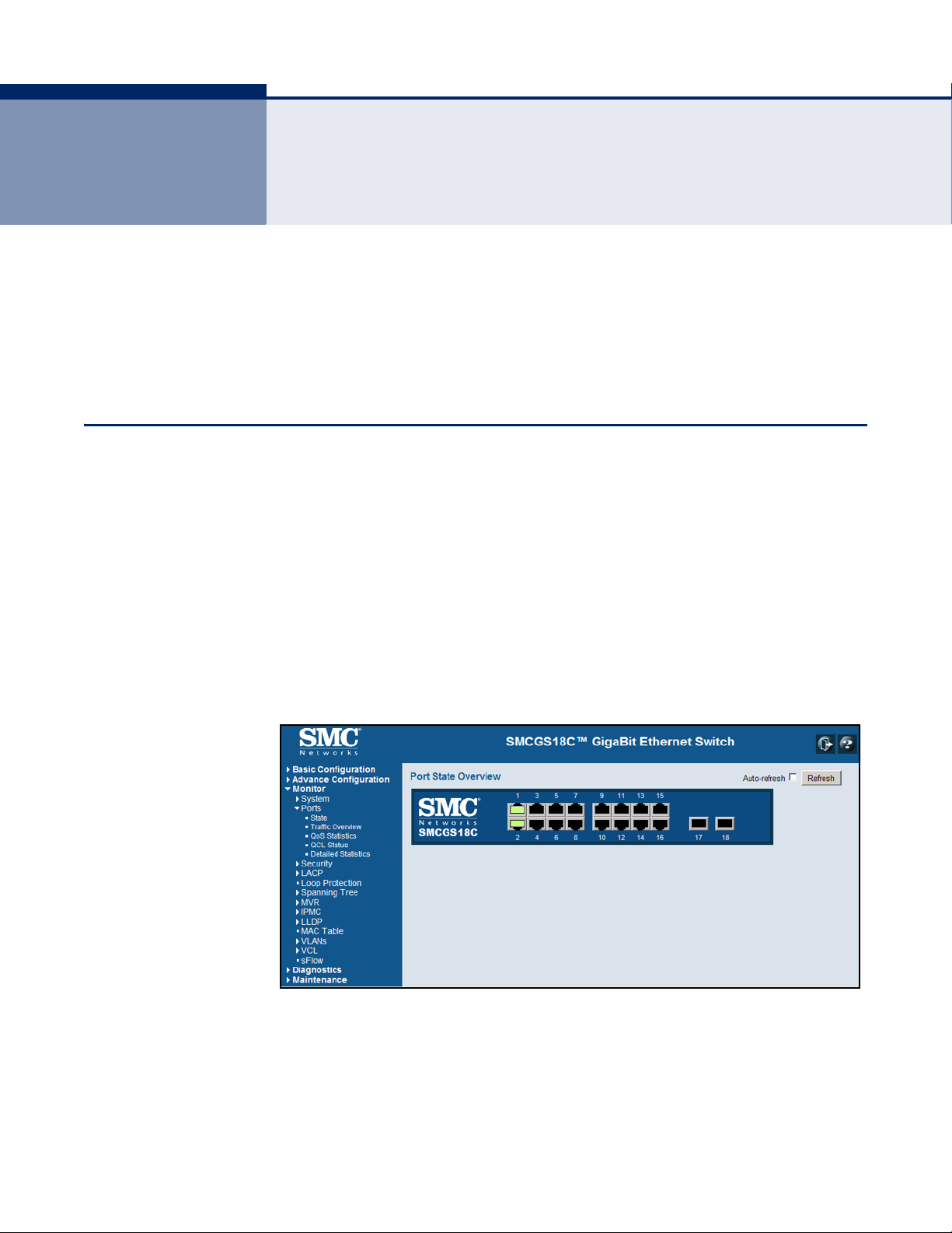
HOME PAGE When your web browser connects with the switch’s web agent, the home
page is displayed as shown below. The home page displays the Main Menu
on the left side of the screen and an image of the front panel on the right
side. The Main Menu links are used to navigate to other menus, and display
configuration parameters and statistics.
Figure 1: Home Page
– 35 –
Page 36
C
HAPTER
3
| Using the Web Interface
Navigating the Web Browser Interface
CONFIGURATION
OPTIONS
Configurable parameters have a dialog box or a drop-down list. Once a
configuration change has been made on a page, be sure to click on the
Save button to confirm the new setting. The following table summarizes
the web page configuration buttons.
Table 3: Web Page Configuration Buttons
Button Action
Save Sets specified values to the system.
Reset Cancels specified values and restores current values prior to pressing
“Save.”
Logs out of the management interface.
Displays help for the selected page.
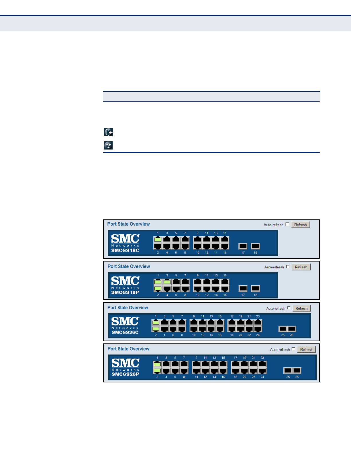
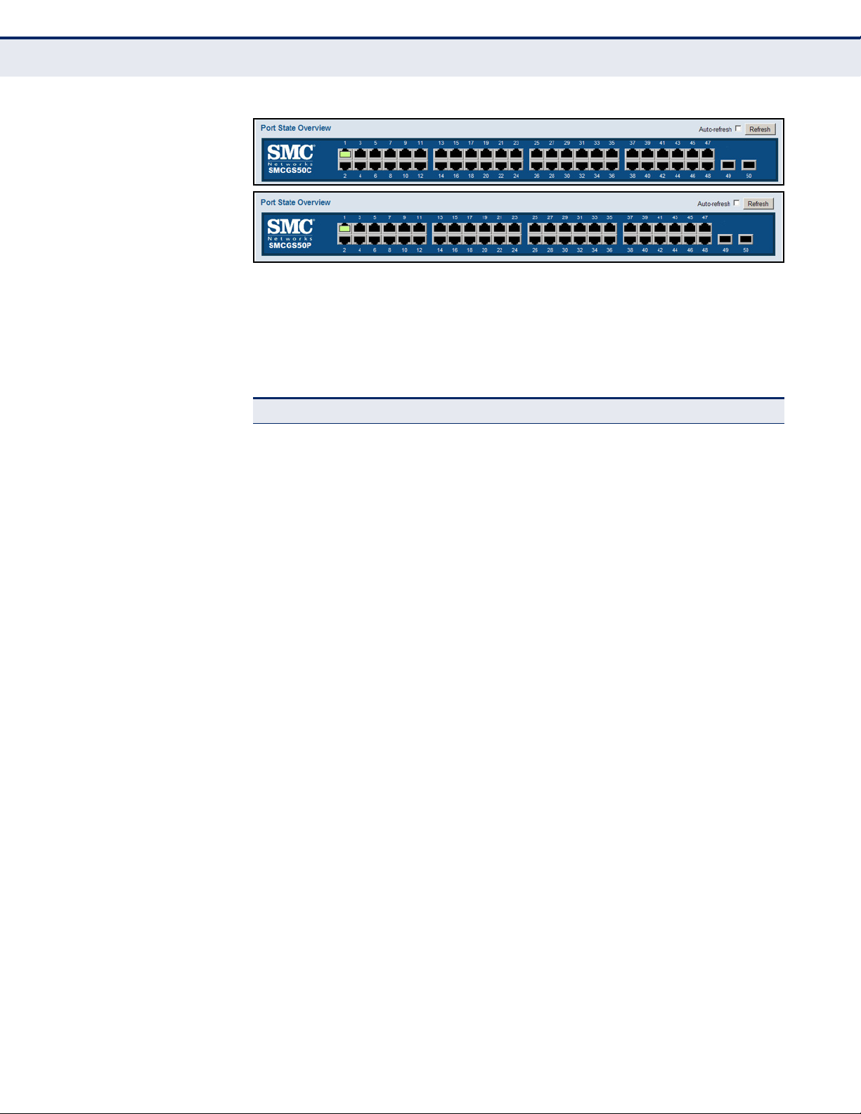
PANEL DISPLAY The web agent displays an image of the switch’s ports. The refresh mode is
disabled by default. Click Auto-refresh to refresh the data displayed on the
screen approximately once every 5 seconds, or click Refresh to refresh the
screen right now. Clicking on the image of a port opens the Detailed
Statistics page as described on page 229.
Figure 2: Front Panel Indicators
– 36 –
Page 37
C
HAPTER
3
| Using the Web Interface
Navigating the Web Browser Interface
MAIN MENU Using the onboard web agent, you can define system parameters, manage
and control the switch, and all its ports, or monitor network conditions. The
following table briefly describes the selections available from this program.
Table 4: Main Menu
Menu Description Page
Basic Configuration
System 45
Information Configures system contact, name and location 45
1
45
IP Configures IPv4 and SNTP settings 46
IPv6 Configures IPv6 and SNTP settings 47
NTP Enables NTP, and configures a list of NTP servers 50
Time Configures the time zone and daylight savings time 51
Log Configures the logging of messages to a remote logging
Ports Configures port connection settings 55
Aggregation 119
Static Specifies ports to group into static trunks 120
LACP Allows ports to dynamically join trunks 122
Spanning Tree 126
Bridge Settings Configures global bridge settings for STP, RSTP and MSTP;
MSTI Mapping Maps VLANs to a specific MSTP instance 132
MSTI Priorities Configures the priority for the CIST and each MISTI 134
CIST Ports Configures interface settings for STA 135
MSTI Ports Configures interface settings for an MST instance 139
MAC Table Configures address aging, dynamic learning, and static
VLANs Virtual LANs 173
VLAN Membership Configures VLAN groups 174
process, specifies the remote log server, and limits the type
of system log messages sent
also configures edge port settings for BPDU filtering, BPDU
guard, and port error recovery
addresses
53
129
171
Ports Specifies default PVID and VLAN attributes 175
Mirroring & RSPAN Sets source and target ports for local or remote mirroring 208
– 37 –
Page 38

C
HAPTER
3
| Using the Web Interface
Navigating the Web Browser Interface
Table 4: Main Menu (Continued)
Menu Description Page
Advanced
Configuration
System
2
Information Configures system contact, name and location 45
IP Configures IPv4 and SNTP settings 46
IPv6 Configures IPv6 and SNTP settings 47
NTP Enables NTP, and configures a list of NTP servers 50
Time Configures the time zone and daylight savings time 51
Log Configures the logging of messages to a remote logging
Power Reduction 54
EEE Configures Energy Efficient Ethernet for specified queues,
2
Ports
Security 57
Switch 57
Users Configures user names, passwords, and access levels 58
Privilege Levels Configures privilege level for specific functions 60
Auth Method Configures authentication method for management access
SSH Configures the Secure Shell server 64
HTTPS Configures secure HTTP settings 65
Access
Management
SNMP Simple Network Management Protocol 67
System Configures read-only and read/write community strings for
process, specifies the remote log server, and limits the type
of system log messages sent
and specifies urgent queues which are to transmit data after
maximum latency expires regardless queue length
Configures port connection settings 55
via local database, RADIUS or TACACS+
Sets IP addresses of clients allowed management access via
HTTP/HTTPS, and SNMP, and Telnet/SSH
SNMP v1/v2c, engine ID for SNMP v3, and trap parameters
53
54
61
66
68
Communities Configures community strings 72
Users Configures SNMP v3 users on this switch 73
Groups Configures SNMP v3 groups 74
Views Configures SNMP v3 views 75
Access Assigns security model, security level, and read/write views
RMON Remote Monitoring 77
Statistics Enables collection of statistics on a physical interface 78
History Periodically samples statistics on a physical interface 78
Alarm Sets threshold bounds for a monitored variable 80
Event Creates a response for an alarm 82
to SNMP groups
– 38 –
76
Page 39

C
HAPTER
3
| Using the Web Interface
Navigating the Web Browser Interface
Table 4: Main Menu (Continued)
Menu Description Page
Network
Limit Control Configures port security limit controls, including secure
NAS Configures global and port settings for IEEE 802.1X 85
ACL Access Control Lists 96
Ports Assigns ACL, rate limiter, and other parameters to ports 96
Rate Limiters Configures rate limit policies 98
Access Control
List
DHCP Dynamic Host Configuration Protocol
Snooping Enables DHCP snooping globally; and sets the trust mode for
Relay Configures DHCP relay information status and policy 109
IP Source Guard Filters IP traffic based on static entries in the IP Source
Configuration Enables IP source guard and sets the maximum number of
Static Table Adds a static addresses to the source-guard binding table 113
ARP Inspection Address Resolution Protocol Inspection 114
Configuration Enables inspection globally, and per port 115
Static Table Adds static entries based on port, VLAN ID, and source MAC
address aging; and per port security, including maximum
allowed MAC addresses, and response for security breach
Configures ACLs based on frame type, destination MAC type,
VLAN ID, VLAN priority tag; and the action to take for
matching packets
each port
Guard table, or dynamic entries in the DHCP Snooping table
clients that can learned dynamically
address and IP address in ARP request packets
83
99
107
111
111
116
AAA Configures RADIUS authentication server, RADIUS
Aggregation
Static Specifies ports to group into static trunks 120
LACP Allows ports to dynamically join trunks 122
Loop Protection Detects general loopback conditions caused by hardware
Spanning Tree
Bridge Settings Configures global bridge settings for STP, RSTP and MSTP;
MSTI Mapping Maps VLANs to a specific MSTP instance 132
MSTI Priorities Configures the priority for the CIST and each MISTI 134
CIST Ports Configures interface settings for STA 135
MSTI Ports Configures interface settings for an MST instance 139
MVR Configures Multicast VLAN Registration, including global
2
accounting server, and TACACS+ authentication server
settings
problems or faulty protocol settings
2
also configures edge port settings for BPDU filtering, BPDU
guard, and port error recovery
status, MVR VLAN, port mode, and immediate leave
117
119
124
126
129
140
– 39 –
Page 40

C
HAPTER
3
| Using the Web Interface
Navigating the Web Browser Interface
Table 4: Main Menu (Continued)
Menu Description Page
IPMC IP Multicast
IGMP Snooping Internet Group Management Protocol Snooping 146
Basic
Configuration
Configures global and port settings for multicast filtering 146
VLAN
Configuration
Port Group
Configures IGMP snooping per VLAN interface 150
Configures multicast groups to be filtered on specified port 152
Filtering
MLD Snooping Multicast Listener Discovery Snooping 153
Basic
Configures global and port settings for multicast filtering 153
Configuration
VLAN
Configuration
Port Group
Filtering
Configures MLD snooping per VLAN interface 156
Configures multicast groups to be filtered on specified port 158
LLDP Link Layer Discovery Protocol 159
LLDP Configures global LLDP timing parameters, and port-specific
LLDP-MED Configures LLDP-MED attributes, including device location,
MAC Table
VLANs
2
2
TLV attributes
emergency call server, and network policy discovery
Configures address aging, dynamic learning, and static
addresses
Virtual LANs 173
159
162
171
VLAN Membership Configures VLAN groups 174
Ports Specifies default PVID and VLAN attributes 175
Private VLANs
PVLAN
Membership
Configures PVLAN groups 178
Port Isolation Prevents communications between designated ports within
3
PoE
the same private VLAN
Configures Power-over-Ethernet settings for each port 168
179
VCL VLAN Control List
MAC-based VLAN Maps traffic with specified source MAC address to a VLAN 180
Protocol-based
VLAN
Protocol to
Group
Creates a protocol group, specifying supported protocols 182
181
Group to VLAN Maps a protocol group to a VLAN for specified ports 183
IP Subnet-based
VLAN
Maps traffic for a specified IP subnet to a VLAN 184
Voice VLAN 186
Configuration Configures global settings, including status, voice VLAN ID,
VLAN aging time, and traffic priority; also configures port
settings, including the way in which a port is added to the
186
Voice VLAN, and blocking non-VoIP addresses
– 40 –
Page 41

C
HAPTER
3
| Using the Web Interface
Navigating the Web Browser Interface
Table 4: Main Menu (Continued)
Menu Description Page
OUI Maps the OUI in the source MAC address of ingress packets
QoS 189
Port Classification Configures default traffic class, drop priority, user priority,
Port Policing Controls the bandwidth provided for frames entering the
to the VoIP device manufacturer
drop eligible indicator, classification mode for tagged frames,
and DSCP-based QoS classification
ingress queue of specified ports.
188
190
192
Port Scheduler Provides overview of QoS Egress Port Schedulers, including
Port Shaping Provides overview of QoS Egress Port Shapers, including the
Port Tag
Remarking
Port DSCP Configures ingress translation and classification settings and
DSCP-Based QoS Configures DSCP-based QoS ingress classification settings 200
DSCP Translation Configures DSCP translation for ingress traffic or DSCP re-
DSCP
Classification
QoS Control List Configures QoS policies for handling ingress packets based
Storm Control Sets limits for broadcast, multicast, and unknown unicast
Mirroring & RSPAN
UPnP Enables UPNP and defines timeout values 216
sFlow Samples traffic flows, and forwards data to designated
Monitor 221
System 221
the queue mode and weight; also configures egress queue
mode, queue shaper (rate and access to excess bandwidth),
and port shaper
rate for each queue and port; also configures egress queue
mode, queue shaper (rate and access to excess bandwidth),
and port shaper
Provides overview of QoS Egress Port Tag Remarking; also
sets the remarking mode (classified PCP/DEI values, default
PCP/DEI values, or mapped versions of QoS class and drop
priority)
egress re-writing of DSCP values
mapping for egress traffic
Maps DSCP values to a QoS class and drop precedence level 202
on Ethernet type, VLAN ID, TCP/UDP port, DSCP, ToS, or
VLAN priority tag
traffic
2
Sets source and target ports for local or remote mirroring 208
collector
193
196
196
199
201
203
207
217
Information Displays basic system description, switch’s MAC address,
CPU Load Displays graphic scale of CPU utilization 222
Log Displays logged messages based on severity 223
Detailed Log Displays detailed information on each logged message 225
Thermal Protection Shows the current chip temperature 225
Ports 226
State Displays a graphic image of the front panel indicating active
system time, and software version
port connections
– 41 –
221
226
Page 42

C
HAPTER
3
| Using the Web Interface
Navigating the Web Browser Interface
Table 4: Main Menu (Continued)
Menu Description Page
Traffic Overview Shows basic Ethernet port statistics 227
QoS Statistics Shows the number of packets entering and leaving the
QCL Status Shows the status of QoS Control List entries 228
Detailed Statistics Shows detailed Ethernet port statistics 229
Security 232
Access
Management
Statistics
Network
Port Security
Switch Shows information about MAC address learning for each
Port Shows the entries authorized by port security services,
NAS Shows global and port settings for IEEE 802.1X
Switch Shows port status for authentication services, including
Port Displays authentication statistics for the selected port –
ACL Status Shows the status for different security modules which use
DHCP Dynamic Host Configuration Protocol
egress queues
Displays the number of packets used to manage the switch
via HTTP, HTTPS, and SNMP, Telnet, and SSH
port, including the software module requesting port security
services, the service state, the current number of learned
addresses, and the maximum number of secure addresses
allowed
including MAC address, VLAN ID, the service state, time
added to table, age, and hold state
802.1X security state, last source address used for
authentication, and last ID
either for 802.1X protocol or for the remote authentication
server depending on the authentication method
ACL filtering, including ingress port, frame type, and
forwarding action
227
232
233
234
235
236
240
Snooping
Statistics
Relay
Statistics
ARP Inspection Displays entries in the ARP inspection table, sorted first by
IP Source Guard Displays entries in the IP Source Guard table, sorted first by
AAA Authentication, Authorization and Accounting 246
RADIUS
Overview
RADIUS Details Displays the traffic and status associated with each
Switch
RMON Remote Monitoring 250
Statistics Shows sampled data for each entry in the statistics group 250
History Shows sampled data for each entry in the history group 252
Shows statistics for various types of DHCP protocol packets 242
Displays server and client statistics for packets affected by
the relay information policy
port, then VLAN ID, MAC address, and finally IP address
port, then VLAN ID, MAC address, and finally IP address
Displays status of configured RADIUS authentication and
accounting servers
configured RADIUS server
– 42 –
243
245
245
246
247
Page 43

C
HAPTER
3
| Using the Web Interface
Navigating the Web Browser Interface
Table 4: Main Menu (Continued)
Menu Description Page
Alarm Shows all configured alarms 253
Event Shows all logged events 254
LACP Link Aggregation Control Protocol 255
System Status Displays administration key and associated local ports for
Port Status Displays administration key, LAG ID, partner ID, and partner
Port Statistics Displays statistics for LACP protocol messages 256
Loop Protection Displays settings, current status, and time of last detected
Spanning Tree 258
Bridge Status Displays global bridge and port settings for STA 258
Port Status Displays STA role, state, and uptime for each port 260
Port Statistics Displays statistics for RSTP, STP and TCN protocol packets 261
MVR Multicast VLAN Registration 262
each partner
ports for each local port
loop
255
255
257
Statistics Shows statistics for IGMP protocol messages used by MVR 262
MVR Channel
Groups
MVR SFM
Information
IPMC IP Multicast
IGMP Snooping 265
Status Displays statistics related to IGMP packets passed upstream
Group
Information
IPv4 SFM
Information
MLD Snooping Multicast Listener Discovery Snooping 268
Status Displays MLD querier status and protocol statistics 268
Group
Information
IPv6 SFM
Information
LLDP Link Layer Discovery Protocol 271
Neighbors Displays LLDP information about a remote device connected
LLDP-MED
Neighbors
Shows information about the interfaces associated with
multicast groups assigned to the MVR VLAN
Displays MVR Source-Filtered Multicast information including
group, filtering mode (include or exclude), source address,
and type (allow or deny)
to the IGMP Querier or downstream to multicast clients
Displays active IGMP groups 266
Displays IGMP Source-Filtered Multicast information
including group, filtering mode (include or exclude), source
address, and type (allow or deny)
Displays active MLD groups 269
Displays MLD Source-Filtered Multicast information including
group, filtering mode (include or exclude), source address,
and type (allow or deny)
to a port on this switch
Displays information about a remote device connected to a
port on this switch which is advertising LLDP-MED TLVs,
including network connectivity device, endpoint device,
capabilities, application type, and policy
263
264
265
267
270
271
272
– 43 –
Page 44

C
HAPTER
3
| Using the Web Interface
Navigating the Web Browser Interface
Table 4: Main Menu (Continued)
Menu Description Page
3
PoE
EEE Displays Energy Efficient Ethernet information advertised
Port Statistics Displays statistics for all connected remote devices, and
3
PoE
Displays status of all LLDP PoE neighbors, including power
device type (PSE or PD), source of power, power priority, and
maximum required power
through LLDP messages
statistics for LLDP protocol packets crossing each port
Displays the status for all PoE ports, including the PD class,
requested power, allocated power, power and current used,
and PoE priority
275
276
277
279
MAC Table Displays dynamic and static address entries associated with
VLANs Virtual LANs 281
VLAN Membership Shows the current port members for all VLANs configured by
VLAN Port Shows the VLAN attributes of port members for all VLANs
VCL VLAN Control List
MAC-based VLAN Displays MAC address to VLAN map entries 283
sFlow Displays information on sampled traffic, including the owner,
Diagnostics 287
Ping Tests specified path using IPv4 ping 287
Ping6 Tests specified path using IPv6 ping 287
Maintenance 289
Restart Device Restarts the switch 289
Factory Defaults Restores factory default settings 290
Software
Upload Updates software on the switch with a file specified on the
the CPU and each port
a selected software module
configured by a selected software module which uses VLAN
management, including PVID, VLAN aware, ingress filtering,
frame type, egress filtering, and PVID
receiver address, remaining sampling time, and statistics for
UDP control packets and sampled traffic
management station
280
281
282
284
290
Image Select Displays information about the active and alternate (backup)
Configuration 292
Save Saves configuration settings to a file on the management
Upload Restores configuration settings from a file on the
1. The Basic Configuration menu is a subset of Advanced Configuration. The following
configuration chapter is therefore structured on the Advanced Configuration menu.
2. These menus are repeated from the Basic Configuration folder.
3. These menus are only provided for PoE switches.
firmware images in the switch, and allows you to revert to
the alternate image
station
management station
– 44 –
291
292
292
Page 45

4 CONFIGURING THE SWITCH
This chapter describes all of the basic configuration tasks.
CONFIGURING SYSTEM INFORMATION
Use the System Information Configuration page to identify the system by
configuring contact information, system name, and the location of the
switch.
PATH
Basic/Advanced Configuration, System, Information
PARAMETERS
These parameters are displayed:
◆ System Contact – Administrator responsible for the system.
(Maximum length: 255 characters)
◆ System Name – Name assigned to the switch system.
(Maximum length: 255 characters)
◆ System Location – Specifies the system location.
(Maximum length: 255 characters)
WEB INTERFACE
To configure System Information:
1. Click Configuration, System, Information.
2. Specify the contact information for the system administrator, as well as
the name and location of the switch.Click Save.
Figure 3: System Information Configuration
– 45 –
Page 46

C
HAPTER
Setting an IP Address
4
| Configuring the Switch
SETTING AN IP ADDRESS
This section describes how to configure an IP interface for management
access to the switch over the network. This switch supports both IP Version
4 and Version 6, and can be managed simultaneously through either of
these address types. You can manually configure a specific IPv4 or IPv6
address or direct the switch to obtain an IPv4 address from a DHCP server
when it is powered on. An IPv6 address can either be manually configured
or dynamically generated.
SETTING AN IPV4
DDRESS
A
Use the IP Configuration page to configure an IPv4 address for the switch.
The IP address for the switch is obtained via DHCP by default for VLAN 1.
To manually configure an address, you need to change the switch's default
settings to values that are compatible with your network. You may also
need to a establish a default gateway between the switch and management
stations that exist on another network segment.
N
OTE
:
An IPv4 address for this switch is obtained via DHCP by default. If
the switch does not receive a response from a DHCP server, it will default
to the IP address 192.168.1.10 and subnet mask 255.255.255.0.
You can manually configure a specific IP address, or direct the device to
obtain an address from a DHCP server. Valid IPv4 addresses consist of four
decimal numbers, 0 to 255, separated by periods. Anything other than this
format will not be accepted by the CLI program.
PATH
Basic/Advanced Configuration, System, IP
PARAMETERS
These parameters are displayed:
IP Configuration
◆ DHCP Client – Specifies whether IP functionality is enabled via
Dynamic Host Configuration Protocol (DHCP). If DHCP is enabled, IP
will not function until a reply has been received from the server.
Requests will be broadcast periodically by the switch for an IP address.
DHCP values can include the IP address, subnet mask, and default
gateway. (Default: Enabled)
◆ IP Address – Address of the VLAN specified in the VLAN ID field. This
should be the VLAN to which the management station is attached. Valid
IP addresses consist of four numbers, 0 to 255, separated by periods.
(Default: 192.168.1.10)
◆ IP Mask – This mask identifies the host address bits used for routing
to specific subnets. (Default: 255.255.255.0)
– 46 –
Page 47

C
HAPTER
◆ IP Router – IP address of the gateway router between the switch and
management stations that exist on other network segments.
◆ VLAN ID – ID of the configured VLAN. By default, all ports on the
switch are members of VLAN 1. However, the management station can
be attached to a port belonging to any VLAN, as long as that VLAN has
been assigned an IP address. (Range: 1-4095; Default: 1)
◆ DNS Server – A Domain Name Server to which client requests for
mapping host names to IP addresses are forwarded.
IP DNS Proxy Configuration
◆ DNS Proxy – If enabled, the switch maintains a local database based
on previous responses to DNS queries forwarded on behalf of attached
clients. If the required information is not in the local database, the
switch forwards the DNS query to a DNS server, stores the response in
its local cache for future reference, and passes the response back to the
client.
4
| Configuring the Switch
Setting an IP Address
WEB INTERFACE
To configure an IP address:
1. Click Configuration, System, IP.
2. Specify the IPv4 settings, and enable DNS proxy service if required.
3. Click Save.
Figure 4: IP Configuration
SETTING AN IPV6
DDRESS
A
Use the IPv6 Configuration page to configure an IPv6 address for
management access to the switch.
IPv6 includes two distinct address types - link-local unicast and global
unicast. A link-local address makes the switch accessible over IPv6 for all
devices attached to the same local subnet. Management traffic using this
– 47 –
Page 48

C
HAPTER
Setting an IP Address
4
| Configuring the Switch
kind of address cannot be passed by any router outside of the subnet. A
link-local address is easy to set up, and may be useful for simple networks
or basic troubleshooting tasks. However, to connect to a larger network
with multiple segments, the switch must be configured with a global
unicast address. A link-local address must be manually configured, but a
global unicast address can either be manually configured or dynamically
assigned.
PATH
Basic/Advanced Configuration, System, IPv6
USAGE GUIDELINES
◆ All IPv6 addresses must be formatted according to RFC 2373 “IPv6
Addressing Architecture,” using 8 colon-separated 16-bit hexadecimal
values. One double colon may be used in the address to indicate the
appropriate number of zeros required to fill the undefined fields.
◆ When configuring a link-local address, note that the prefix length is
fixed at 64 bits, and the host portion of the default address is based on
the modified EUI-64 (Extended Universal Identifier) form of the
interface identifier (i.e., the physical MAC address). You can manually
configure a link-local address by entering the full address with the
network prefix FE80.
◆ To connect to a larger network with multiple subnets, you must
configure a global unicast address. There are several alternatives to
configuring this address type:
■
The global unicast address can be automatically configured by
taking the network prefix from router advertisements observed on
the local interface, and using the modified EUI-64 form of the
interface identifier to automatically create the host portion of the
address. This option can be selected by enabling the Auto
Configuration option.
■
You can also manually configure the global unicast address by
entering the full address and prefix length.
◆ The management VLAN to which the IPv6 address is assigned must be
specified on the IP Configuration page. See "Setting an IPv4 Address"
on page 46.
PARAMETERS
These parameters are displayed:
◆ Auto Configuration – Enables stateless autoconfiguration of IPv6
addresses on an interface and enables IPv6 functionality on the
interface. The network portion of the address is based on prefixes
received in IPv6 router advertisement messages, and the host portion
is automatically generated using the modified EUI-64 form of the
interface identifier; i.e., the switch's MAC address. (Default: Disabled)
– 48 –
Page 49
C
HAPTER
4
| Configuring the Switch
Setting an IP Address
◆ Address – Manually configures a global unicast address by specifying
the full address and network prefix length (in the Prefix field).
(Default: ::192.168.1.10)
◆ Prefix – Defines the prefix length as a decimal value indicating how
many contiguous bits (starting at the left) of the address comprise the
prefix; i.e., the network portion of the address. (Default: 96 bits)
Note that the default prefix length of 96 bits specifies that the first six
colon-separated values comprise the network portion of the address.
◆ Router – Sets the IPv6 address of the default next hop router.
An IPv6 default gateway must be defined if the management station is
located in a different IPv6 segment.
An IPv6 default gateway can only be successfully set when a network
interface that directly connects to the gateway has been configured on
the switch.
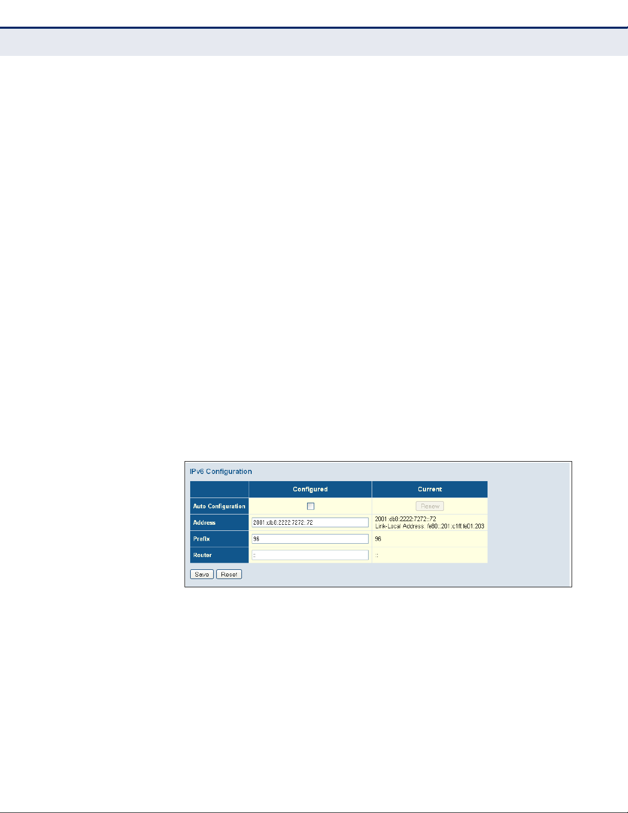
WEB INTERFACE
To configure an IPv6 address:
1. Click Configuration, System, IPv6.
2. Specify the IPv6 settings. The information shown below provides a
example of how to manually configure an IPv6 address.
3. Click Save.
Figure 5: IPv6 Configuration
– 49 –
Page 50
C
HAPTER
Configuring NTP Service
4
| Configuring the Switch
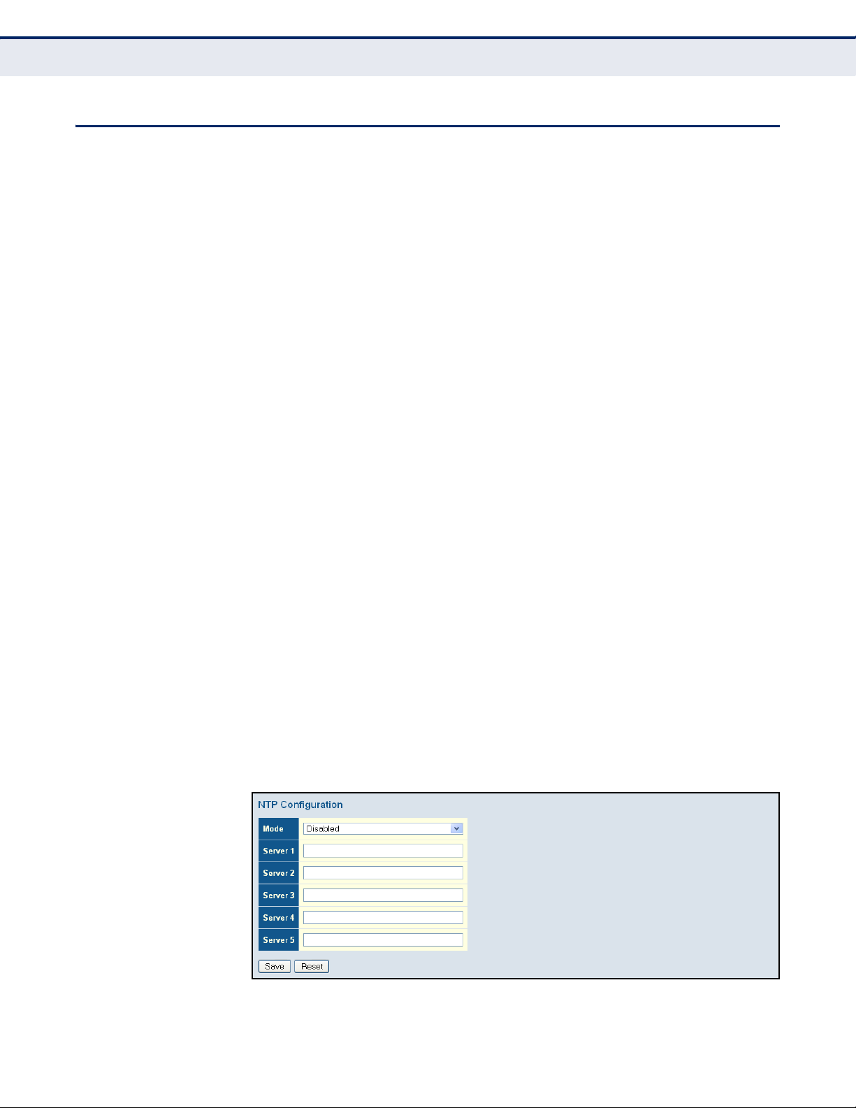
CONFIGURING NTP SERVICE
Use the NTP Configuration page to specify the Network Time Protocol (NTP)
servers to query for the current time. NTP allows the switch to set its
internal clock based on periodic updates from an NTP time server.
Maintaining an accurate time on the switch enables the system log to
record meaningful dates and times for event entries. If the clock is not set,
the switch will only record the time from the factory default set at the last
bootup.
When the NTP client is enabled, the switch periodically sends a request for
a time update to a configured time server. You can configure up to five time
server IP addresses. The switch will attempt to poll each server in the
configured sequence.
PATH
Basic/Advanced Configuration, System, NTP
PARAMETERS
These parameters are displayed:
◆ Mode – Enables or disables NTP client requests.
◆ Server – Sets the IPv4 or IPv6 address for up to five time servers. The
switch attempts to update the time from the first server, if this fails it
attempts an update from the next server in the sequence. The polling
interval is fixed at 15 minutes.
WEB INTERFACE
To configure the NTP servers:
1. Click Configuration, System, NTP.
2. Enter the IP address of up to five time servers.
3. Click Save.
Figure 6: NTP Configuration
– 50 –
Page 51

C
HAPTER
Configuring the Time Zone and Daylight Savings Time
CONFIGURING THE TIME ZONE AND DAYLIGHT SAVINGS TIME
Use the Time Zone and Daylight Savings Time page to set the time zone
and Daylight Savings Time.
Time Zone – NTP/SNTP uses Coordinated Universal Time (or UTC, formerly
Greenwich Mean Time, or GMT) based on the time at the Earth’s prime
meridian, zero degrees longitude, which passes through Greenwich,
England. To display a time corresponding to your local time, you must
indicate the number of hours and minutes your time zone is east (before)
or west (after) of UTC. You can choose one of the 80 predefined time zone
definitions, or your can manually configure the parameters for your local
time zone.
Daylight Savings Time – In some countries or regions, clocks are adjusted
through the summer months so that afternoons have more daylight and
mornings have less. This is known as Daylight Savings Time or Summer
Time. Typically, clocks are adjusted forward one hour at the start of spring
and then adjusted backward in autumn.
4
| Configuring the Switch
PATH
Basic/Advanced Configuration, System, Time
PARAMETERS
These parameters are displayed:
Time Zone Configuration
◆ Time Zone – A drop-down box provides access to the 80 predefined
time zone configurations. Each choice indicates it’s offset from UTC and
lists at least one major city or location covered by the time zone.
◆ Acronym – Sets the acronym of the time zone. (Range: Up to 16
alphanumeric characters, as well as the symbols ‘-’, ‘_’ or ‘.’)
Daylight Saving Time Configuration
◆ Mode – Selects one of the following configuration modes.
■
Disabled – Daylight Savings Time is not used.
■
Recurring – Sets the start, end, and offset times of summer time
for the switch on a recurring basis. This mode sets the summertime zone relative to the currently configured time zone.
■
From – Start time for summer-time.
■
To – End time for summer-time.
■
Offset – The number of minutes to add during Daylight Saving
Time. (Range: 1-1440)
– 51 –
Page 52
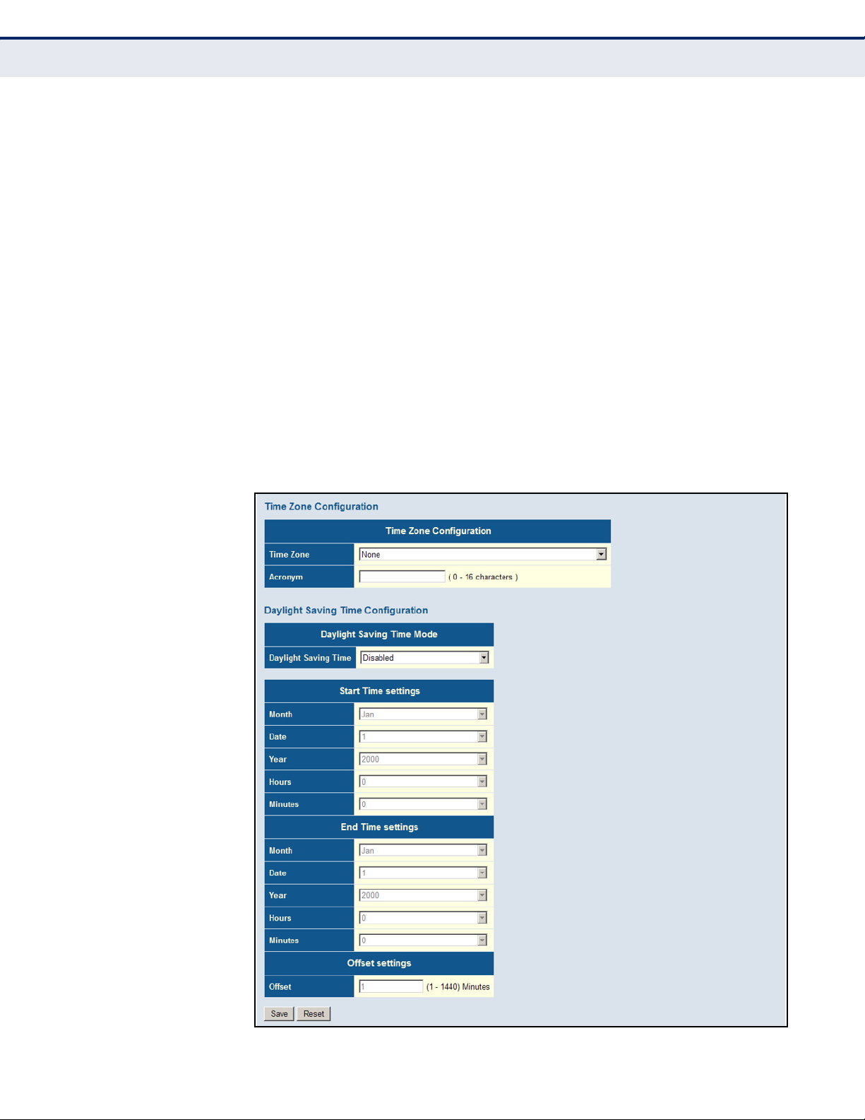
C
HAPTER
Configuring the Time Zone and Daylight Savings Time
4
| Configuring the Switch
■
Non-Recurring – Sets the start, end, and offset times of summer
time for the switch on a one-time basis.
■
From – Start time for summer-time.
■
To – End time for summer-time.
■
Offset – The number of minutes to add during Daylight Saving
Time. (Range: 1-1440)
WEB INTERFACE
To set the time zone or Daylight Savings Time:
1. Click Configuration, System, Time.
2. Select one of the predefined time zones.
3. Select the Daylight Savings Time mode, and then set the start, end and
offset times.
4. Click Save.
Figure 7: Time Zone and Daylight Savings Time Configuration
– 52 –
Page 53

CONFIGURING REMOTE LOG MESSAGES
Use the System Log Configuration page to send log messages to syslog
servers or other management stations. You can also limit the event
messages sent to specified types.
PATH
Basic/Advanced Configuration, System, Log
COMMAND USAGE
When remote logging is enabled, system log messages are sent to the
designated server. The syslog protocol is based on UDP and received on
UDP port 514. UDP is a connectionless protocol and does not provide
acknowledgments. The syslog packet will always be sent out even if the
syslog server does not exist.
PARAMETERS
These parameters are displayed:
C
HAPTER
4
| Configuring the Switch
Configuring Remote Log Messages
◆ Server Mode – Enables/disables the logging of debug or error
messages to the remote logging process. (Default: Disabled)
◆ Server Address – Specifies the IPv4 address or alias of a remote
server which will be sent syslog messages.
◆ Syslog Level – Limits log messages that are sent to the remote syslog
server for the specified types. Messages options include the following:
■
Info – Send informations, warnings and errors. (Default setting)
■
Warning – Send warnings and errors.
■
Error – Send errors.
WEB INTERFACE
To configure the logging of error messages to remote servers:
1. Click Configuration, System, Log.
2. Enable remote logging, enter the IP address of the remote server, and
specify the type of syslog messages to send.
3. Click Apply.
Figure 8: Configuring Settings for Remote Logging of Error Messages
– 53 –
Page 54

C
HAPTER
Configuring Power Reduction
4
| Configuring the Switch
CONFIGURING POWER REDUCTION
The switch provides power saving methods including powering down the
circuitry for port queues when not in use.
REDUCING POWER TO
IDLE QUEUE CIRCUITS
Use the EEE Configuration page to configure Energy Efficient Ethernet
(EEE) for specified queues, and to specify urgent queues which are to
transmit data after maximum latency expires regardless of queue length.
PATH
Advanced Configuration, Power Reduction, EEE
COMMAND USAGE
◆ EEE works by powering down circuits when there is no traffic. When a
port gets data to be transmitted all relevant circuits are powered up.
The time it takes to power up the circuits is call the wakeup time. The
default wakeup time is 17 µs for 1 Gbps links and 30 µs for other link
speeds. EEE devices must agree upon the value of the wakeup time in
order to make sure that both the receiving and transmitting devices
have all circuits powered up when traffic is transmitted. The devices
can exchange information about the device wakeup time using LLDP
protocol.
To maximize power savings, the circuit is not started as soon as data is
ready to be transmitted from a port, but instead waits until 3000 bytes
of data is queued at the port. To avoid introducing a large delay when
the queued data is less then 3000 bytes, data is always transmitted
after 48 µs, giving a maximum latency of 48 µs plus the wakeup time.
◆ If required, it is possible to minimize the latency for specific frames by
mapping the frames to a specific queue (EEE Urgent Queues). When an
urgent queue gets data to be transmitted, the circuits will be powered
up at once and the latency will be reduced to the wakeup time.
PARAMETERS
These parameters are displayed:
◆ Port – Port identifier.
◆ EEE Enabled – Enables or disables EEE for the specified port.
◆ EEE Urgent Queues – Specifies which are to transmit data after the
maximum latency expires regardless queue length.
WEB INTERFACE
To configure the power reduction for idle queue circuits:
1. Click Configuration, Power Reduction, EEE.
2. Select the circuits which will use EEE.
– 54 –
Page 55

C
HAPTER
4
| Configuring the Switch
Configuring Port Connections
3. If required, also specify urgent queues which will be powered up once
data is queued and the default wakeup time has passed.
4. Click Save.
Figure 9: Configuring EEE Power Reduction
CONFIGURING PORT CONNECTIONS
Use the Port Configuration page to configure the connection parameters for
each port. This page includes options for enabling auto-negotiation or
manually setting the speed and duplex mode, enabling flow control, setting
the maximum frame size, specifying the response to excessive collisions,
or enabling power saving mode.
PATH
Basic/Advanced Configuration, Ports – The Disabled option was removed
from the Speed - Configured field on
PARAMETERS
These parameters are displayed:
◆ Link – Indicates if the link is up or down.
◆ Speed – Sets the port speed and duplex mode using auto-negotiation
or manual selection. The following options are supported:
■
Disabled - Disables the interface. You can disable an interface due
to abnormal behavior (e.g., excessive collisions), and then reenable it after the problem has been resolved. You may also disable
an interface for security reasons. (Not applicable to Ports 1 and 2.)
■
Auto - Enables auto-negotiation. When using auto-negotiation, the
optimal settings will be negotiated between the link partners based
on their advertised capabilities.
■
1Gbps FDX - Supports 1 Gbps full-duplex operation
– 55 –
Page 56

C
HAPTER
Configuring Port Connections
4
| Configuring the Switch
■
100Mbps FDX - Supports 100 Mbps full-duplex operation
■
100Mbps HDX - Supports 100 Mbps half-duplex operation
■
10Mbps FDX - Supports 10 Mbps full-duplex operation
■
10Mbps HDX - Supports 10 Mbps half-duplex operation
(Default: Autonegotiation enabled; Advertised capabilities for
RJ-45: 1000BASE-T - 10half, 10full, 100half, 100full, 1000full;
SFP: 1000BASE-SX/LX/LH - 1000full)
N
OTE
:
The 1000BASE-T standard does not support forced mode. Autonegotiation should always be used to establish a connection over any
1000BASE-T port or trunk. If not used, the success of the link process
cannot be guaranteed when connecting to other types of switches.
◆ Flow Control – Flow control can eliminate frame loss by “blocking”
traffic from end stations or segments connected directly to the switch
when its buffers fill. When enabled, back pressure is used for halfduplex operation and IEEE 802.3-2005 (formally IEEE 802.3x) for fullduplex operation. (Default: Disabled)
When auto-negotiation is used, this parameter indicates the flow
control capability advertised to the link partner. When the speed and
duplex mode are manually set, the Current Rx field indicates whether
pause frames are obeyed by this port, and the Current Tx field indicates
if pause frames are transmitted from this port.
Avoid using flow control on a port connected to a hub unless it is
actually required to solve a problem. Otherwise back pressure jamming
signals may degrade overall performance for the segment attached to
the hub.
◆ Maximum Frame Size – Sets the maximum transfer unit for traffic
crossing the switch. Packets exceeding the maximum frame size are
dropped. (Range: 9600-1518 bytes; Default: 9600 bytes)
◆ Excessive Collision Mode – Sets the response to take when excessive
transmit collisions are detected on a port.
■
Discard - Discards a frame after 16 collisions (default).
■
Restart - Restarts the backoff algorithm after 16 collisions.
◆ Power Control – Adjusts the power provided to ports based on the
length of the cable used to connect to other devices. Only sufficient
power is used to maintain connection requirements.
IEEE 802.3 defines the Ethernet standard and subsequent power
requirements based on cable connections operating at 100 meters.
Enabling power saving mode can significantly reduce power used for
cable lengths of 20 meters or less, and continue to ensure signal
integrity.
The following options are supported:
■
Disabled – All power savings mechanisms disabled (default).
– 56 –
Page 57
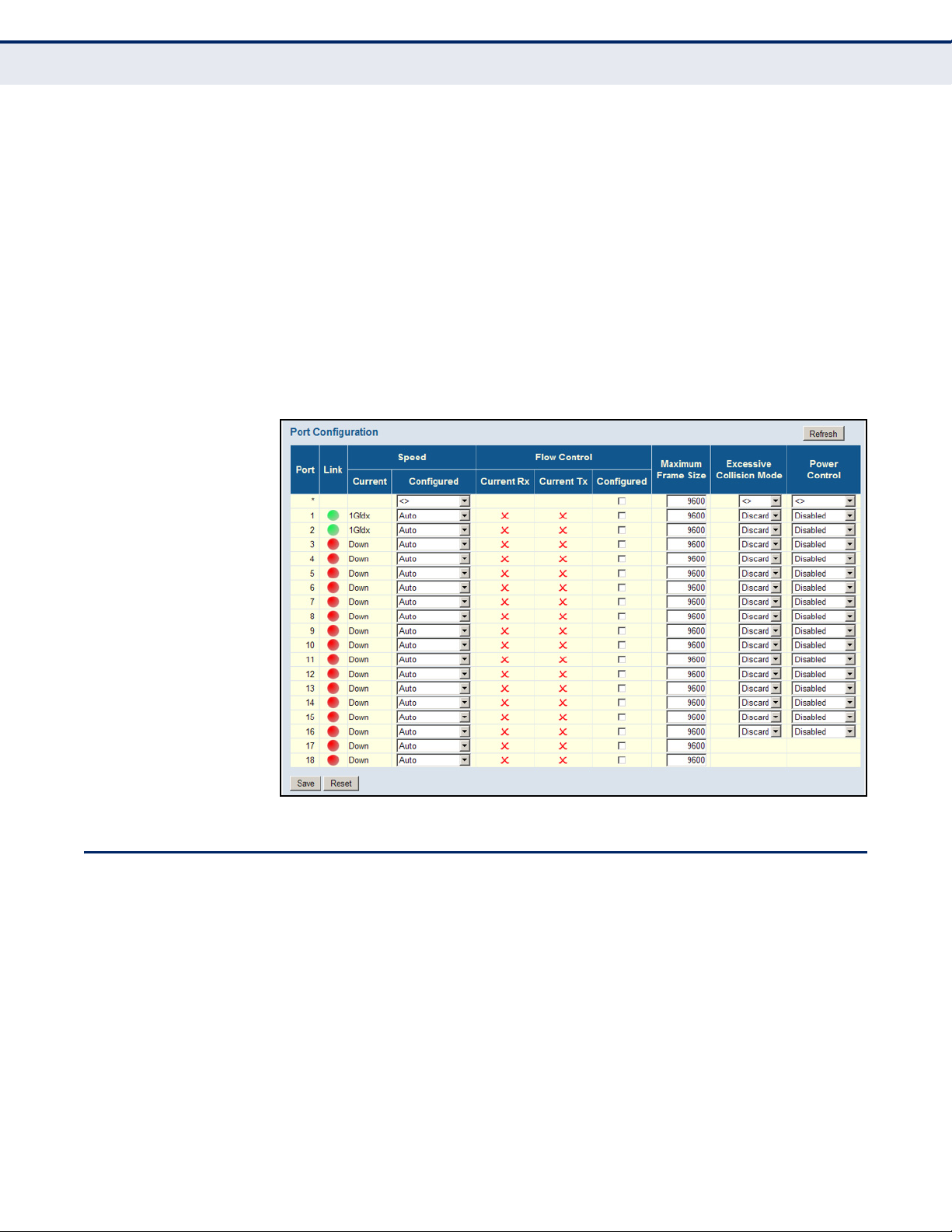
C
HAPTER
■
Enabled – Both link up and link down power savings enabled.
■
ActiPHY – Link down power savings enabled.
■
PerfectReach – Link up power savings enabled.
4
| Configuring the Switch
WEB INTERFACE
To configure port connection settings:
1. Click Configuration, Ports.
2. Make any required changes to the connection settings.
3. Click Save.
Figure 10: Port Configuration
Configuring Security
CONFIGURING SECURITY
You can configure this switch to authenticate users logging into the system
for management access or to control client access to the data ports.
Management Access Security (Switch menu) – Management access to the
switch can be controlled through local authentication of user names and
passwords stored on the switch, or remote authentication of users via a
RADIUS or TACACS+ server. Additional authentication methods includes
Secure Shell (SSH), Secure Hypertext Transfer Protocol (HTTPS) over the
Secure Socket Layer (SSL), static configuration of client addresses, and
SNMP.
General Security Measures (Network menu) – This switch supports many
methods of segregating traffic for clients attached to each of the data
– 57 –
Page 58

C
HAPTER
Configuring Security
4
| Configuring the Switch
ports, and for ensuring that only authorized clients gain access to the
network. Private VLANs and port-based authentication using IEEE 802.1X
are commonly used for these purposes. In addition to these methods,
several other options of providing client security are supported by this
switch. These include limiting the number of users accessing a port. The
addresses assigned to DHCP clients can also be carefully controlled using
static or dynamic bindings with DHCP Snooping and IP Source Guard
commands. ARP Inspection can also be used to validate the MAC address
bindings for ARP packets, providing protection against ARP traffic with
invalid MAC to IP address bindings, which forms the basis for “man-in-themiddle” attacks.
CONFIGURING USER
ACCOUNTS
Use the User Configuration page to control management access to the
switch based on manually configured user names and passwords.
PATH
Advanced Configuration, Security, Switch, Users
COMMAND USAGE
◆ The default guest name is “guest” with the password “guest.” The
default administrator name is “admin” with the password “admin.”
◆ The guest only has read access for most configuration parameters.
However, the administrator has write access for all parameters
governing the onboard agent. You should therefore assign a new
administrator password as soon as possible, and store it in a safe place.
◆ The administrator has a privilege level of 15, with access to all process
groups and full control over the device. If the privilege level is set to
any other value, the system will refer to each group privilege level. The
user's privilege should be same or greater than the group privilege
level to have the access of a group. By default, most of the group
privilege levels are set to 5 which provides read-only access and
privilege level 10 which also provides read/write access. To perform
system maintenance (software upload, factory defaults, etc.) the user’s
privilege level should be set to 15. Generally, the privilege level 15 can
be used for an administrator account, privilege level 10 for a standard
user account, and privilege level 5 for a guest account.
PARAMETERS
These parameters are displayed:
◆ User Name – The name of the user.
(Maximum length: 8 characters; maximum number of users: 16)
◆ Password – Specifies the user password.
(Range: 0-8 characters plain text, case sensitive)
◆ Password (again) – Re-type the string entered in the previous field to
ensure no errors were made. The switch will not change the password if
these two fields do not match.
– 58 –
Page 59

C
HAPTER
4
| Configuring the Switch
Configuring Security
◆ Privilege Level – Specifies the user level. (Options: 1 - 15)
Access to specific functions are controlled through the Privilege Levels
configuration page (see page 60). The default settings provide four
access levels:
■
1 – Read access of port status and statistics.
■
5 – Read access of all system functions except for maintenance and
debugging
■
10 – read and write access of all system functions except for
maintenance and debugging
■
15 – read and write access of all system functions including
maintenance and debugging.
WEB INTERFACE
To show user accounts:
1. Click Advanced Configuration, Security, Switch, Users.
Figure 11: Showing User Accounts
To configure a user account:
1. Click Advanced Configuration, Security, Switch, Users.
2. Click “Add new user.”
3. Enter the user name, password, and privilege level.
4. Click Save.
Figure 12: Configuring User Accounts
– 59 –
Page 60

C
HAPTER
Configuring Security
4
| Configuring the Switch
CONFIGURING USER
PRIVILEGE LEVELS
Use the Privilege Levels page to set the privilege level required to read or
configure specific software modules or system settings.
PATH
Advanced Configuration, Security, Switch, Privilege Levels
PARAMETERS
These parameters are displayed:
◆ Group Name – The name identifying a privilege group. In most cases,
a privilege group consists of a single module (e.g., LACP, RSTP or QoS),
but a few groups contains more than one module. The following
describes the groups which contain multiple modules or access to
various system settings:
■
System: Contact, Name, Location, Timezone, Log.
■
Security: Authentication, System Access Management, Port
(contains Dot1x port, MAC based and the MAC Address Limit), ACL,
HTTPS, SSH, ARP Inspection, and IP source guard.
■
IP: Everything except for ping.
■
Port: Everything.
■
Diagnostics: ping.
■
Maintenance: CLI - System Reboot, System Restore Default,
System Password, Configuration Save, Configuration Load and
Firmware Load. Web - Users, Privilege Levels and everything in
Maintenance.
■
Debug: Only present in CLI.
◆ Privilege levels – Every privilege level group can be configured to
access the following modules or system settings: Configuration Readonly, Configuration/Execute Read-write, Status/Statistics Read-only,
and Status/Statistics Read-write (e.g., clearing statistics).
The default settings provide four access levels:
■
1 – Read access of port status and statistics.
■
5 – Read access of all system functions except for maintenance and
debugging
■
10 – read and write access of all system functions except for
maintenance and debugging
■
15 – read and write access of all system functions including
maintenance and debugging.
WEB INTERFACE
To configure privilege levels:
1. Click Advanced Configuration, Security, Switch, Privilege Levels.
2. Set the required privilege level for any software module or functional
group.
– 60 –
Page 61

3. Click Save.
Figure 13: Configuring Privilege Levels
C
HAPTER
4
| Configuring the Switch
Configuring Security
CONFIGURING THE
AUTHENTICATION
METHOD FOR
MANAGEMENT ACCESS
Use the Authentication Method Configuration page to specify the
authentication method for controlling management access through the
console, Telnet, SSH or HTTP/HTTPS. Access can be based on the (local)
user name and password configured on the switch, or can be controlled
with a RADIUS or TACACS+ remote access authentication server. Note that
the RADIUS servers used to authenticate client access for IEEE 802.1X port
authentication are also configured on this page (see page 85).
Remote Authentication Dial-in User Service (RADIUS) and Terminal Access
Controller Access Control System Plus (TACACS+) are logon authentication
protocols that use software running on a central server to control access to
RADIUS-aware or TACACS-aware devices on the network. An
authentication server contains a database of multiple user name/password
pairs with associated privilege levels for each user that requires
management access to the switch.
– 61 –
Page 62

C
Web
RADIUS/
TACACS+
server
1. Client attempts management access.
2. Switch contacts authentication server.
3.Authentication server challenges client.
4. Client responds with proper password or key.
5.Authentication server approves access.
6. Switch grants management access.
HAPTER
Configuring Security
4
| Configuring the Switch
Figure 14: Authentication Server Operation
PATH
Advanced Configuration, Security, Switch, Auth Method
USAGE GUIDELINES
◆ The switch supports the following authentication services:
■
Authorization of users that access the Telnet, SSH, the web, or
console management interfaces on the switch.
■
Accounting for users that access the Telnet, SSH, the web, or
console management interfaces on the switch.
■
Accounting for IEEE 802.1X authenticated users that access the
network through the switch. This accounting can be used to provide
reports, auditing, and billing for services that users have accessed.
◆ By default, management access is always checked against the
authentication database stored on the local switch. If a remote
authentication server is used, you must specify the authentication
method and the corresponding parameters for the remote
authentication protocol on the Network Access Server Configuration
page. Local and remote logon authentication can be used to control
management access via Telnet, SSH, a web browser, or the console
interface.
◆ When using RADIUS or TACACS+ logon authentication, the user name
and password must be configured on the authentication server. The
encryption methods used for the authentication process must also be
configured or negotiated between the authentication server and logon
client. This switch can pass authentication messages between the
server and client that have been encrypted using MD5 (Message-Digest
5), TLS (Transport Layer Security), or TTLS (Tunneled Transport Layer
Security).
– 62 –
Page 63

C
HAPTER
N
OTE
:
This guide assumes that RADIUS and TACACS+ servers have already
4
| Configuring the Switch
Configuring Security
been configured to support AAA. The configuration of RADIUS and
TACACS+ server software is beyond the scope of this guide. Refer to the
documentation provided with the RADIUS and TACACS+ server software.
PARAMETERS
These parameters are displayed:
◆ Client – Specifies how the administrator is authenticated when logging
into the switch via Telnet, SSH, or a web browser.
◆ Authentication Method – Selects the authentication method.
(Options: None, Local, RADIUS, TACACS+; Default: Local)
Selecting the option “None” disables access through the specified
management interface.
◆ Fallback – Uses the local user database for authentication if none of
the configured authentication servers are alive. This is only possible if
the Authentication Method is set to something else than “none” or
“local.”
WEB INTERFACE
To configure authentication for management access:
1. Click Advanced Configuration, Security, Switch, Auth Method.
2. Configure the authentication method for management client types, and
specify whether or not to fallback to local authentication if no remote
authentication server is available.
3. Click Save.
Figure 15: Authentication Method for Management Access
– 63 –
Page 64

C
HAPTER
Configuring Security
4
| Configuring the Switch
CONFIGURING SSH Use the SSH Configuration page to configure access to the Secure Shell
(SSH) management interface. SSH provides remote management access to
this switch as a secure replacement for Telnet. When the client contacts the
switch via the SSH protocol, the switch generates a public-key that the
client uses along with a local user name and password for access
authentication. SSH also encrypts all data transfers passing between the
switch and SSH-enabled management station clients, and ensures that
data traveling over the network arrives unaltered.
PATH
Advanced Configuration, Security, Switch, SSH
USAGE GUIDELINES
◆ You need to install an SSH client on the management station to access
the switch for management via the SSH protocol. The switch supports
both SSH Version 1.5 and 2.0 clients.
◆ SSH service on this switch only supports password authentication. The
password can be authenticated either locally or via a RADIUS or
TACACS+ remote authentication server, as specified on the Auth
Method menu (page 61).
To use SSH with password authentication, the host public key must still
be given to the client, either during initial connection or manually
entered into the known host file. However, you do not need to configure
the client's keys.
◆ The SSH service on the switch supports up to four client sessions. The
maximum number of client sessions includes both current Telnet
sessions and SSH sessions.
PARAMETERS
These parameters are displayed:
◆ Mode - Allows you to enable/disable SSH service on the switch.
(Default: Enabled)
WEB INTERFACE
To c o nf i gu r e SS H :
1. Click Advanced Configuration, Security, Switch, SSH.
2. Enable SSH if required.
3. Click Save.
Figure 16: SSH Configuration
– 64 –
Page 65

C
HAPTER
4
| Configuring the Switch
Configuring Security
CONFIGURING HTTPS Use the HTTPS Configuration page to enable the Secure Hypertext Transfer
Protocol (HTTPS) over the Secure Socket Layer (SSL). HTTPS provides
secure access (i.e., an encrypted connection) to the switch's web interface.
PATH
Advanced Configuration, Security, Switch, HTTPS
USAGE GUIDELINES
◆ If you enable HTTPS, you must indicate this in the URL that you specify
in your browser: https://device[:port-number]
◆ When you start HTTPS, the connection is established in this way:
■
The client authenticates the server using the server's digital
certificate.
■
The client and server negotiate a set of security protocols to use for
the connection.
■
The client and server generate session keys for encrypting and
decrypting data.
■
The client and server establish a secure encrypted connection.
A padlock icon should appear in the status bar for Internet Explorer
5.x or above, and Mozilla Firefox 2.x or above.
◆ The following web browsers and operating systems currently support
HTTPS:
Table 5: HTTPS System Support
Web Browser Operating System
Internet Explorer 5.0 or later Windows 98,Windows NT (with service pack 6a),
Mozilla Firefox 2.0.0.0 or later Windows 2000, Windows XP, Windows Vista,
Windows 2000, Windows XP, Windows Vista, Windows 7,
Windows 8
Windows 7, Windows 8, Linux
PARAMETERS
These parameters are displayed:
◆ Mode - Enables HTTPS service on the switch. (Default: Enabled)
◆ Automatic Redirect - Sets the HTTPS redirect mode operation. When
enabled, management access to the HTTP web interface for the switch
are automatically redirected to HTTPS. (Default: Disabled)
WEB INTERFACE
To c o nf i gu r e H TT P S:
1. Click Advanced Configuration, HTTPS.
2. Enable HTTPS if required and set the Automatic Redirect mode.
3. Click Save.
– 65 –
Page 66

C
HAPTER
Configuring Security
4
| Configuring the Switch
Figure 17: HTTPS Configuration
FILTERING IP
ADDRESSES FOR
MANAGEMENT ACCESS
Use the Access Management Configuration page to create a list of up to 16
IP addresses or IP address groups that are allowed management access to
the switch through the web interface, or SNMP, or Telnet.
The management interfaces are open to all IP addresses by default. Once
you add an entry to a filter list, access to that interface is restricted to the
specified addresses. If anyone tries to access a management interface on
the switch from an invalid address, the switch will reject the connection.
PATH
Advanced Configuration, Security, Switch, Access Management
PARAMETERS
These parameters are displayed:
◆ Mode – Enables or disables filtering of management access based on
configured IP addresses. (Default: Disabled)
◆ Start IP Address – The starting address of a range.
◆ End IP Address – The ending address of a range.
◆ HTTP/HTTPS – Filters IP addresses for access to the web interface
over standard HTTP, or over HTTPS which uses the Secure Socket Layer
(SSL) protocol to provide an encrypted connection.
◆ SNMP – Filters IP addresses for access through SNMP.
◆ TELNET/SSH – Filters IP addresses for access through Telnet, or
through Secure Shell which provides authentication and encryption.
WEB INTERFACE
To configure addresses allowed access to management interfaces on the
switch:
1. Click Advanced Configuration, Security, Switch, Access Management.
2. Set the Mode to Enabled.
3. Click “Add new entry.”
4. Enter the start and end of an address range.
– 66 –
Page 67

C
HAPTER
4
| Configuring the Switch
Configuring Security
5. Mark the protocols to restrict based on the specified address range. The
following example shows how to restrict management access for all
protocols to a specific address range.
6. Click Save.
Figure 18: Access Management Configuration
USING SIMPLE
NETWORK
MANAGEMENT
PROTOCOL
Simple Network Management Protocol (SNMP) is a communication protocol
designed specifically for managing devices on a network. Equipment
commonly managed with SNMP includes switches, routers and host
computers. SNMP is typically used to configure these devices for proper
operation in a network environment, as well as to monitor them to evaluate
performance or detect potential problems.
Managed devices supporting SNMP contain software, which runs locally on
the device and is referred to as an agent. A defined set of variables, known
as managed objects, is maintained by the SNMP agent and used to manage
the device. These objects are defined in a Management Information Base
(MIB) that provides a standard presentation of the information controlled
by the agent. SNMP defines both the format of the MIB specifications and
the protocol used to access this information over the network.
The switch includes an onboard agent that supports SNMP versions 1, 2c,
and 3. This agent continuously monitors the status of the switch hardware,
as well as the traffic passing through its ports. A network management
station can access this information using software such as HP OpenView.
Access to the onboard agent from clients using SNMP v1 and v2c is
controlled by community strings. To communicate with the switch, the
management station must first submit a valid community string for
authentication.
Access to the switch using from clients using SNMPv3 provides additional
security features that cover message integrity, authentication, and
encryption; as well as controlling user access to specific areas of the MIB
tree.
The SNMPv3 security structure consists of security models, with each
model having it's own security levels. There are three security models
defined, SNMPv1, SNMPv2c, and SNMPv3. Users are assigned to “groups”
that are defined by a security model and specified security levels. Each
group also has a defined security access to set of MIB objects for reading
and writing, which are known as “views.” The switch has a default view (all
– 67 –
Page 68

C
HAPTER
4
| Configuring the Switch
Configuring Security
MIB objects) and default groups defined for security models v1 and v2c.
The following table shows the security models and levels available and the
system default settings.
Table 6: SNMP Security Models and Levels
Model Level Community String Group Read View Write View Security
v1 noAuth
v1 noAuth
NoPriv
NoPriv
public default_ro_group default_view none Community string only
private default_rw_group default_view default_view Community string only
v1 noAuth
v2c noAuth
v2c noAuth
v2c noAuth
v3 noAuth
v3 Auth
v3 Auth Priv user defined user defined user defined user defined Provides user authentication
NoPriv
NoPriv
NoPriv
NoPriv
NoPriv
NoPriv
user defined user defined user defined user defined Community string only
public default_ro_group default_view none Community string only
private default_rw_group default_view default_view Community string only
user defined user defined user defined user defined Community string only
user defined default_rw_group default_view default_view A user name match only
user defined user defined user defined user defined Provides user authentication
N
OTE
:
The predefined default groups and view can be deleted from the
via MD5 or SHA algorithms
via MD5 or SHA algorithms
and data privacy using DES
56-bit encryption
system. You can then define customized groups and views for the SNMP
clients that require access.
CONFIGURING SNMP SYSTEM AND TRAP SETTINGS
Use the SNMP System Configuration page to configure basic settings and
traps for SNMP. To manage the switch through SNMP, you must first enable
the protocol and configure the basic access parameters. To issue trap
messages, the trap function must also be enabled and the destination host
specified.
PATH
Advanced Configuration, Security, Switch, SNMP, System
PARAMETERS
These parameters are displayed:
SNMP System Configuration
◆ Mode - Enables or disables SNMP service. (Default: Disabled)
– 68 –
Page 69

C
HAPTER
4
| Configuring the Switch
Configuring Security
◆ Version - Specifies the SNMP version to use. (Options: SNMP v1,
SNMP v2c, SNMP v3; Default: SNMP v2c)
◆ Read Community - The community used for read-only access to the
SNMP agent. (Range: 0-255 characters, ASCII characters 33-126 only;
Default: public)
This parameter only applies to SNMPv1 and SNMPv2c. SNMPv3 uses the
User-based Security Model (USM) for authentication and privacy. This
community string is associated with SNMPv1 or SNMPv2 clients in the
SNMPv3 Communities table (page 72).
◆ Write Community - The community used for read/write access to the
SNMP agent. (Range: 0-255 characters, ASCII characters 33-126 only;
Default: private)
This parameter only applies to SNMPv1 and SNMPv2c. SNMPv3 uses the
User-based Security Model (USM) for authentication and privacy. This
community string is associated with SNMPv1 or SNMPv2 clients in the
SNMPv3 Communities table (page 72).
◆ Engine ID - The SNMPv3 engine ID. (Range: 10-64 hex digits,
excluding a string of all 0’s or all F’s; Default: 800007e5017f000001)
An SNMPv3 engine is an independent SNMP agent that resides on the
switch. This engine protects against message replay, delay, and
redirection. The engine ID is also used in combination with user
passwords to generate the security keys for authenticating and
encrypting SNMPv3 packets.
A local engine ID is automatically generated that is unique to the
switch. This is referred to as the default engine ID. If the local engine
ID is deleted or changed, all local SNMP users will be cleared. You will
need to reconfigure all existing users.
SNMP Trap Configuration
◆ Trap Mode - Enables or disables SNMP traps. (Default: Disabled)
You should enable SNMP traps so that key events are reported by this
switch to your management station. Traps indicating status changes
can be issued by the switch to the specified trap manager by sending
authentication failure messages and other trap messages.
◆ Trap Version - Indicates if the target user is running SNMP v1, v2c, or
v3. (Default: SNMP v1)
◆ Trap Community - Specifies the community access string to use when
sending SNMP trap packets. (Range: 0-255 characters, ASCII
characters 33-126 only; Default: public)
◆ Trap Destination Address - IPv4 address of the management station
to receive notification messages.
◆ Trap Destination IPv6 Address - IPv6 address of the management
station to receive notification messages. An IPv6 address must be
formatted according to RFC 2373 “IPv6 Addressing Architecture,” using
– 69 –
Page 70

C
HAPTER
Configuring Security
4
| Configuring the Switch
8 colon-separated 16-bit hexadecimal values. One double colon may be
used to indicate the appropriate number of zeros required to fill the
undefined fields.
◆ Trap Authentication Failure - Issues a notification message to
specified IP trap managers whenever authentication of an SNMP
request fails. (Default: Enabled)
◆ Trap Link-up and Link-down - Issues a notification message
whenever a port link is established or broken. (Default: Enabled)
◆ Trap Inform Mode - Enables or disables sending notifications as
inform messages. Note that this option is only available for version 2c
and 3 hosts. (Default: traps are used)
The recipient of a trap message does not send a response to the switch.
Traps are therefore not as reliable as inform messages, which include a
request for acknowledgement of receipt. Informs can be used to ensure
that critical information is received by the host. However, note that
informs consume more system resources because they must be kept in
memory until a response is received. Informs also add to network
traffic. You should consider these effects when deciding whether to
issue notifications as traps or informs.
◆ Trap Inform Timeout - The number of seconds to wait for an
acknowledgment before resending an inform message. (Range: 0-2147
seconds; Default: 1 second)
◆ Trap Inform Retry Times - The maximum number of times to resend
an inform message if the recipient does not acknowledge receipt.
(Range: 0-255; Default: 5)
◆ Trap Probe Security Engine ID (SNMPv3) - Specifies whether or not
to use the engine ID of the SNMP trap probe in trap and inform
messages. (Default: Enabled)
◆ Trap Security Engine ID (SNMPv3) - Indicates the SNMP trap security
engine ID. SNMPv3 sends traps and informs using USM for
authentication and privacy. A unique engine ID for these traps and
informs is needed. When “Trap Probe Security Engine ID” is enabled,
the ID will be probed automatically. Otherwise, the ID specified in this
field is used. (Range: 10-64 hex digits, excluding a string of all 0’s or all
F’s)
N
OTE
:
The Trap Probe Security Engine ID must be disabled before an
engine ID can be manually entered in this field.
◆ Trap Security Name (SNMPv3) - Indicates the SNMP trap security
name. SNMPv3 traps and informs use USM for authentication and
privacy. A unique security name is needed when SNMPv3 traps or
informs are enabled.
– 70 –
Page 71

C
HAPTER
N
OTE
:
To select a name from this field, first enter an SNMPv3 user with the
4
| Configuring the Switch
Configuring Security
same Trap Security Engine ID in the SNMPv3 Users Configuration menu
(see "Configuring SNMPv3 Users" on page 73).
WEB INTERFACE
To configure SNMP system and trap settings:
1. Click Advanced Configuration, Security, Switch, SNMP, System.
2. In the SNMP System Configuration table, set the Mode to Enabled to
enable SNMP service on the switch, specify the SNMP version to use,
change the community access strings if required, and set the engine ID
if SNMP version 3 is used.
3. In the SNMP Trap Configuration table, enable the Trap Mode to allow
the switch to send SNMP traps. Specify the trap version, trap
community, and IP address of the management station that will receive
trap messages either as an IPv4 or IPv6 address. Select the trap types
to issue, and set the trap inform settings for SNMP v2c or v3 clients.
For SNMP v3 clients, configure the security engine ID and security
name used in v3 trap and inform messages.
4. Click Save.
Figure 19: SNMP System Configuration
– 71 –
Page 72
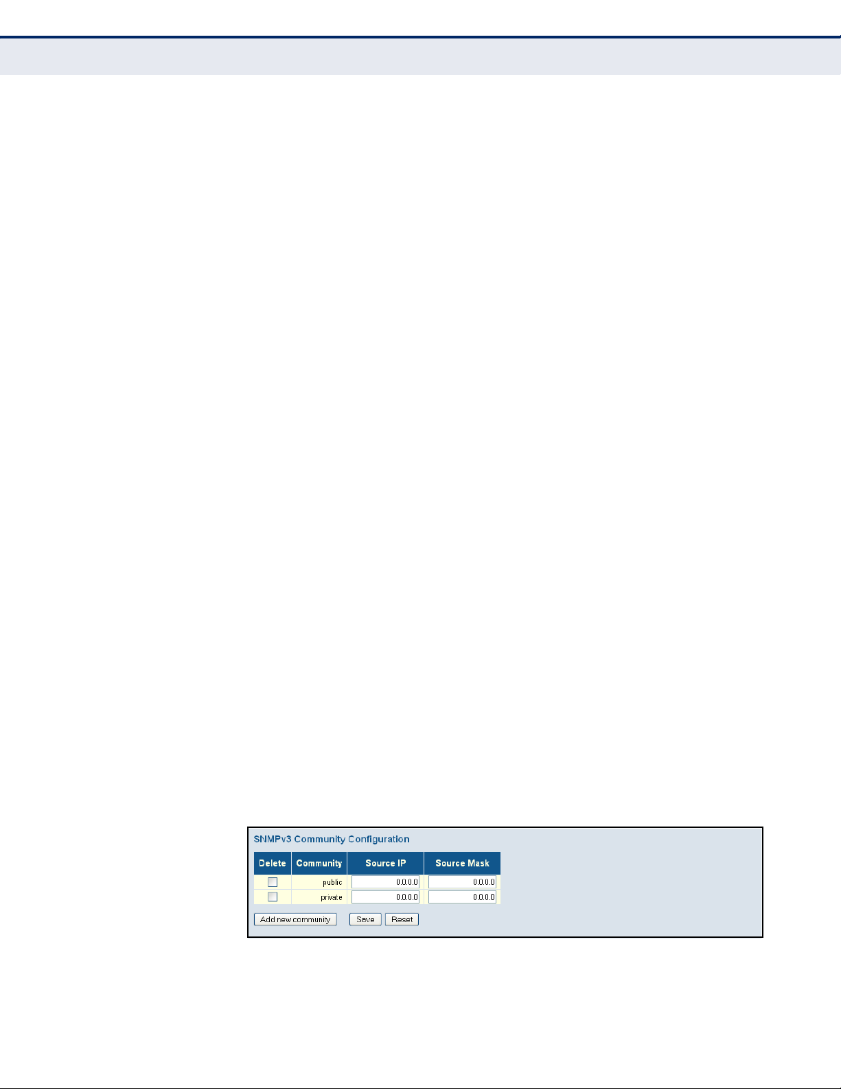
C
HAPTER
Configuring Security
4
| Configuring the Switch
SETTING SNMPV3 COMMUNITY ACCESS STRINGS
Use the SNMPv3 Community Configuration page to set community access
strings. All community strings used to authorize access by SNMP v1 and
v2c clients should be listed in the SNMPv3 Communities Configuration
table. For security reasons, you should consider removing the default
strings.
PATH
Advanced Configuration, Security, Switch, SNMP, Communities
PARAMETERS
These parameters are displayed:
◆ Community - Specifies the community strings which allow access to
the SNMP agent. (Range: 1-32 characters, ASCII characters 33-126
only; Default: public, private)
For SNMPv3, these strings are treated as a Security Name, and are
mapped as an SNMPv1 or SNMPv2 community string in the SNMPv3
Groups Configuration table (see "Configuring SNMPv3 Groups" on
page 74).
◆ Source IP - Specifies the source address of an SNMP client.
◆ Source Mask - Specifies the address mask for the SNMP client.
WEB INTERFACE
To configure SNMP community access strings:
1. Click Advanced Configuration, Security, Switch, SNMP, Communities.
2. Set the IP address and mask for the default community strings.
Otherwise, you should consider deleting these strings for security
reasons.
3. Add any new community strings required for SNMPv1 or v2 clients that
need to access the switch, along with the source address and address
mask for each client.
4. Click Save.
Figure 20: SNMPv3 Community Configuration
– 72 –
Page 73

C
HAPTER
4
| Configuring the Switch
Configuring Security
CONFIGURING SNMPV3 USERS
Use the SNMPv3 User Configuration page to define a unique name and
remote engine ID for each SNMPv3 user. Users must be configured with a
specific security level, and the types of authentication and privacy
protocols to use.
N
OTE
:
Any user assigned through this page is associated with the group
assigned to the USM Security Model on the SNMPv3 Groups Configuration
page (page 74), and the views assigned to that group in the SNMPv3
Access Configuration page (page 76).
PATH
Advanced Configuration, Security, Switch, SNMP, Users
PARAMETERS
These parameters are displayed:
◆ Engine ID - The engine identifier for the SNMP agent on the remote
device where the user resides. (Range: 10-64 hex digits, excluding a
string of all 0’s or all F’s)
To send inform messages to an SNMPv3 user on a remote device, you
must first specify the engine identifier for the SNMP agent on the
remote device where the user resides. The remote engine ID is used to
compute the security digest for authenticating and encrypting packets
sent to a user on the remote host.
SNMP passwords are localized using the engine ID of the authoritative
agent. For informs, the authoritative SNMP agent is the remote agent.
You therefore need to configure the remote agent's SNMP engine ID
before you can send proxy requests or informs to it. (See "Configuring
SNMP System and Trap Settings" on page 68.)
◆ User Name - The name of user connecting to the SNMP agent.
(Range: 1-32 characters, ASCII characters 33-126 only)
◆ Security Level - The security level assigned to the user:
■
NoAuth, NoPriv - There is no authentication or encryption used in
SNMP communications. (This is the default for SNMPv3.)
■
Auth, NoPriv - SNMP communications use authentication, but the
data is not encrypted.
■
Auth, Priv - SNMP communications use both authentication and
encryption.
◆ Authentication Protocol - The method used for user authentication.
(Options: None, MD5, SHA; Default: MD5)
◆ Authentication Password - A plain text string identifying the
authentication pass phrase. (Range: 1-32 characters for MD5, 8-40
characters for SHA)
– 73 –
Page 74

C
HAPTER
Configuring Security
4
| Configuring the Switch
◆ Privacy Protocol - The encryption algorithm use for data privacy; only
56-bit DES is currently available. (Options: None, DES; Default: DES)
◆ Privacy Password - A string identifying the privacy pass phrase.
(Range: 8-40 characters, ASCII characters 33-126 only)
WEB INTERFACE
To configure SNMPv3 users:
1. Click Advanced Configuration, Security, Switch, SNMP, Users.
2. Click “Add new user” to configure a user name.
3. Enter a remote Engine ID of up to 64 hexadecimal characters
4. Define the user name, security level, authentication and privacy
settings.
5. Click Save.
Figure 21: SNMPv3 User Configuration
CONFIGURING SNMPV3 GROUPS
Use the SNMPv3 Group Configuration page to configure SNMPv3 groups.
An SNMPv3 group defines the access policy for assigned users, restricting
them to specific read and write views as defined on the SNMPv3 Access
Configuration page (page 76). You can use the pre-defined default groups,
or create a new group and the views authorized for that group.
PATH
Advanced Configuration, Security, Switch, SNMP, Groups
PARAMETERS
These parameters are displayed:
◆ Security Model - The user security model. (Options: SNMP v1, v2c, or
the User-based Security Model – usm).
◆ Security Name - The name of a user connecting to the SNMP agent.
(Range: 1-32 characters, ASCII characters 33-126 only)
The options displayed for this parameter depend on the selected
Security Model. For SNMP v1 and v2c, the switch displays the names
configured on the SNMPv3 Communities Configuration menu (see
page 72). For USM (or SNMPv3), the switch displays the names
configured with the local engine ID in the SNMPv3 Users Configuration
– 74 –
Page 75

C
HAPTER
menu (see page 73). To modify an entry for USM, the current entry
must first be deleted.
◆ Group Name - The name of the SNMP group. (Range: 1-32 characters,
ASCII characters 33-126 only)
4
| Configuring the Switch
Configuring Security
WEB INTERFACE
To configure SNMPv3 groups:
1. Click Advanced Configuration, Security, Switch, SNMP, Groups.
2. Click “Add new group” to set up a new group.
3. Select a security model.
4. Select the security name. For SNMP v1 and v2c, the security names
displayed are based on the those configured in the SNMPv3
Communities menu. For USM, the security names displayed are based
on the those configured in the SNMPv3 Users Configuration menu.
5. Enter a group name. Note that the views assigned to a group must be
specified on the SNMP Accesses Configuration menu (see page 76).
6. Click Save.
Figure 22: SNMPv3 Group Configuration
CONFIGURING SNMPV3 VIEWS
Use the SNMPv3 View Configuration page to define views which restrict
user access to specified portions of the MIB tree. The predefined view
“default_view” includes access to the entire MIB tree.
CLI REFERENCES
"SNMP Commands" on page 330
PARAMETERS
These parameters are displayed:
◆ View Name - The name of the SNMP view. (Range: 1-32 characters,
ASCII characters 33-126 only)
– 75 –
Page 76

C
HAPTER
Configuring Security
4
| Configuring the Switch
◆ View Type - Indicates if the object identifier of a branch within the MIB
tree is included or excluded from the SNMP view. Generally, if the view
type of an entry is “excluded,” another entry of view type “included”
should exist and its OID subtree should overlap the “excluded” view
entry.
◆ OID Subtree - Object identifiers of branches within the MIB tree. Note
that the first character must be a period (.). Wild cards can be used to
mask a specific portion of the OID string using an asterisk.
(Length: 1-128)
WEB INTERFACE
To configure SNMPv3 views:
1. Click Advanced Configuration, Security, Switch, SNMP, Views.
2. Click “Add new view” to set up a new view.
3. Enter the view name, view type, and OID subtree.
4. Click Save.
Figure 23: SNMPv3 View Configuration
CONFIGURING SNMPV3 GROUP ACCESS RIGHTS
Use the SNMPv3 Access Configuration page to assign portions of the MIB
tree to which each SNMPv3 group is granted access. You can assign more
than one view to a group to specify access to different portions of the MIB
tree.
PATH
Advanced Configuration, Security, Switch, SNMP, Access
PARAMETERS
These parameters are displayed:
◆ Group Name - The name of the SNMP group. (Range: 1-32 characters,
ASCII characters 33-126 only)
◆ Security Model - The user security model. (Options: any, v1, v2c, or
the User-based Security Model – usm; Default: any)
◆ Security Level - The security level assigned to the group:
■
NoAuth, NoPriv - There is no authentication or encryption used in
SNMP communications. (This is the default for SNMPv3.)
– 76 –
Page 77

C
HAPTER
■
Auth, NoPriv - SNMP communications use authentication, but the
4
| Configuring the Switch
Configuring Security
data is not encrypted.
■
Auth, Priv - SNMP communications use both authentication and
encryption.
◆ Read View Name - The configured view for read access. (Range: 1-32
characters, ASCII characters 33-126 only)
◆ Write View Name - The configured view for write access.
(Range: 1-32 characters, ASCII characters 33-126 only)
WEB INTERFACE
To configure SNMPv3 group access rights:
1. Click Advanced Configuration, Security, Switch, SNMP, Access.
2. Click Add New Access to create a new entry.
3. Specify the group name, security settings, read view, and write view.
4. Click Save.
Figure 24: SNMPv3 Access Configuration
REMOTE MONITORING Remote Monitoring allows a remote device to collect information or
respond to specified events on an independent basis. This switch is an
RMON-capable device which can independently perform a wide range of
tasks, significantly reducing network management traffic. It can
continuously run diagnostics and log information on network performance.
If an event is triggered, it can automatically notify the network
administrator of a failure and provide historical information about the
event. If it cannot connect to the management agent, it will continue to
perform any specified tasks and pass data back to the management station
the next time it is contacted.
The switch supports mini-RMON, which consists of the Statistics, History,
Event and Alarm groups. When RMON is enabled, the system gradually
builds up information about its physical interfaces, storing this information
in the relevant RMON database group. A management agent then
periodically communicates with the switch using the SNMP protocol.
However, if the switch encounters a critical event, it can automatically send
a trap message to the management agent which can then respond to the
event if so configured.
– 77 –
Page 78

C
HAPTER
Configuring Security
4
| Configuring the Switch
CONFIGURING RMON STATISTICAL SAMPLES
Use the RMON Statistics Configuration page to collect statistics on a port,
which can subsequently be used to monitor the network for common errors
and overall traffic rates.
PATH
Advanced Configuration, Security, RMON, Statistics
COMMAND USAGE
◆ If statistics collection is already enabled on an interface, the entry must
be deleted before any changes can be made.
◆ The information collected for each entry includes: drop events, input
octets, packets, broadcast packets, multicast packets, CRC alignment
errors, undersize packets, oversize packets, fragments, jabbers,
collisions, and frames of various sizes.
PARAMETERS
The following parameters are displayed:
◆ ID - Index to this entry. (Range: 1-65535)
◆ Data Source – Port identifier.
WEB INTERFACE
To enable regular sampling of statistics on a port:
1. Click Advanced Configuration, Security, Switch, RMON, Statistics.
2. Click Add New Entry.
3. Enter the index identifier and port number.
4. Click Save.
Figure 25: RMON Statistics Configuration
CONFIGURING RMON HISTORY SAMPLES
Use the RMON History Configuration page to collect statistics on a physical
interface to monitor network utilization, packet types, and errors. A
historical record of activity can be used to track down intermittent
problems. The record can be used to establish normal baseline activity,
which may reveal problems associated with high traffic levels, broadcast
storms, or other unusual events. It can also be used to predict network
– 78 –
Page 79

C
HAPTER
4
| Configuring the Switch
Configuring Security
growth and plan for expansion before your network becomes too
overloaded.
PATH
Advanced Configuration, Security, RMON, History
COMMAND USAGE
The information collected for each sample includes: drop events, input
octets, packets, broadcast packets, multicast packets, CRC alignment
errors, undersize packets, oversize packets, fragments, jabbers, collisions,
and network utilization.
PARAMETERS
The following parameters are displayed:
◆ ID - Index to this entry. (Range: 1-65535)
◆ Data Source – Port identifier.
◆ Interval - The polling interval. (Range: 1-3600 seconds; Default: 1800
seconds)
◆ Buckets - The number of buckets requested for this entry.
(Range: 1-3600; Default: 50)
◆ Buckets Granted - The number of buckets granted.
WEB INTERFACE
To periodically sample statistics on a port:
1. Click Advanced Configuration, Security, Switch, RMON, History.
2. Click Add New Entry.
3. Enter the index identifier, port number, sampling interval, and
maximum number of buckets requested.
4. Click Save.
Figure 26: RMON History Configuration
– 79 –
Page 80

C
HAPTER
Configuring Security
4
| Configuring the Switch
CONFIGURING RMON ALARMS
Use the RMON Alarm Configuration page to define specific criteria that will
generate response events. Alarms can be set to test data over any
specified time interval, and can monitor absolute or changing values (such
as a statistical counter reaching a specific value, or a statistic changing by
a certain amount over the set interval). Alarms can be set to respond to
rising or falling thresholds. However, note that after an alarm is triggered it
will not be triggered again until the statistical value crosses the opposite
bounding threshold and then back across the trigger threshold.
PATH
Advanced Configuration, Security, RMON, Alarm
PARAMETERS
The following parameters are displayed:
◆ ID – Index to this entry. (Range: 1-65535)
◆ Interval – The polling interval. (Range: 1-2^31 seconds)
◆ Variable – The object identifier of the MIB variable to be sampled.
Only variables of the type ifEntry.n.n may be sampled.
Note that ifEntry.n uniquely defines the MIB variable, and ifEntry.n.n
defines the MIB variable, plus the ifIndex. For example,
1.3.6.1.2.1.2.2.1.1.10.1 denotes ifInOctets, plus the ifIndex of 1.
Possible variables (ifEntry.n, where n = 10-21) include: InOctets,
InUcastPkts, InNUcastPkts, InDiscards, InErrors, InUnknownProtos,
OutOctets, OutUcastPkts, OutNUcastPkts, OutDiscards, OutErrors, and
OutQLen.
◆ Sample Type – Tests for absolute or relative changes in the specified
variable.
■
Absolute – The variable is compared directly to the thresholds at
the end of the sampling period.
■
Delta – The last sample is subtracted from the current value and
the difference is then compared to the thresholds.
◆ Value – The value of the statistic during the last sampling period.
◆ Startup Alarm – The method of sampling the selected variable and
calculating the value to be compared against the thresholds. Possible
sample types include:
■
Rising – Trigger alarm when the first value is larger than the rising
threshold.
■
Falling – Trigger alarm when the first value is less than the falling
threshold.
– 80 –
Page 81

C
HAPTER
■
Rising or Falling – Trigger alarm when the first value is larger than
4
| Configuring the Switch
Configuring Security
the rising threshold or less than the falling threshold (default).
◆ Rising Threshold – If the current value is greater than the rising
threshold, and the last sample value was less than this threshold, then
an alarm will be generated. After a rising event has been generated,
another such event will not be generated until the sampled value has
fallen below the rising threshold, reaches the falling threshold, and
again moves back up to the rising threshold. (Range: -2147483647 to
2147483647)
◆ Rising Index – The index of the event to use if an alarm is triggered
by monitored variables crossing above the rising threshold. If there is
no corresponding entry in the event control table, then no event will be
generated. (Range: 1-65535)
◆ Falling Threshold – If the current value is less than the falling
threshold, and the last sample value was greater than this threshold,
then an alarm will be generated. After a falling event has been
generated, another such event will not be generated until the sampled
value has risen above the falling threshold, reaches the rising
threshold, and again moves back down to the failing threshold.
(Range: -2147483647 to 2147483647)
◆ Falling Index – The index of the event to use if an alarm is triggered
by monitored variables crossing below the falling threshold. If there is
no corresponding entry in the event control table, then no event will be
generated. (Range: 1-65535)
WEB INTERFACE
To configure an RMON alarm:
1. Click Advanced Configuration, Security, Switch, RMON, Alarm.
2. Click Add New Entry.
3. Enter an index number, the polling interval, the MIB object to be polled
(etherStatsEntry.n.n), the sample type, the alarm startup type, the
thresholds, and the event to trigger.
4. Click Save.
Figure 27: RMON Alarm Configuration
– 81 –
Page 82

C
HAPTER
Configuring Security
4
| Configuring the Switch
CONFIGURING RMON EVENTS
Use the RMON Event Configuration page to set the action to take when an
alarm is triggered. The response can include logging the alarm or sending a
message to a trap manager. Alarms and corresponding events provide a
way of immediately responding to critical network problems.
PATH
Advanced Configuration, Security, RMON, Event
PARAMETERS
The following parameters are displayed:
◆ ID – Index to this entry. (Range: 1-65535)
◆ Desc – A comment that describes this event. (Range: 0-127
characters)
◆ Type – Specifies the type of event to initiate:
■
none – No event is generated.
■
log – Generates an RMON log entry when the event is triggered.
Log messages are processed based on the current configuration
settings for event logging (see "Configuring Remote Log Messages"
on page 53).
■
snmptrap – Sends a trap message to all configured trap managers
(see "Configuring SNMP System and Trap Settings" on page 68).
■
logandtrap – Logs the event and sends a trap message.
◆ Community – A password-like community string sent with the trap
operation to SNMP v1 and v2c hosts.
Although the community string can be set on this configuration page, it
is recommended that it be defined on the SNMP trap configuration page
(see "Setting SNMPv3 Community Access Strings" on page 72) prior to
configuring it here. (Range: 0-127 characters)
◆ Last Event Time – The value of sysUpTime when an event was last
generated for this entry.
WEB INTERFACE
To configure an RMON event:
1. Click Advanced Configuration, Security, Switch, RMON, Event.
2. Click Add New Entry.
3. Enter an index number, a brief description of the event, the type of
event to initiate, and the community string to send with trap messages.
4. Click Save.
– 82 –
Page 83
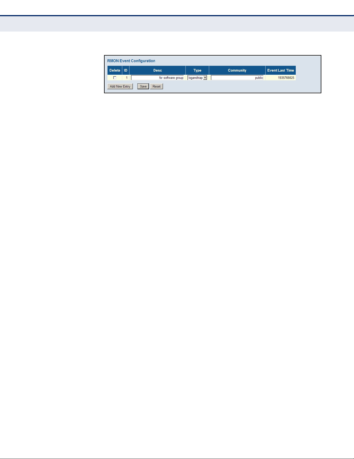
Figure 28: RMON Event Configuration
C
HAPTER
4
| Configuring the Switch
Configuring Security
CONFIGURING PORT
LIMIT CONTROLS
Use the Port Security Limit Control Configuration page to limit the number
of users accessing a given port. A user is identified by a MAC address and
VLAN ID. If Limit Control is enabled on a port, the maximum number of
users on the port is restricted to the specified limit. If this number is
exceeded, the switch makes the specified response.
PATH
Advanced Configuration, Security, Network, Limit Control
PARAMETERS
The following parameters are displayed:
System Configuration
◆ Mode – Enables or disables Limit Control is globally on the switch. If
globally disabled, other modules may still use the underlying
functionality, but limit checks and corresponding actions are disabled.
◆ Aging Enabled – If enabled, secured MAC addresses are subject to
aging as discussed under Aging Period.
With aging enabled, a timer is started once the end-host gets secured.
When the timer expires, the switch starts looking for frames from the
end-host, and if such frames are not seen within the next Aging Period,
the end-host is assumed to be disconnected, and the corresponding
resources are freed on the switch.
◆ Aging Period – If Aging Enabled is checked, then the aging period is
controlled with this parameter. If other modules are using the
underlying port security for securing MAC addresses, they may have
other requirements for the aging period. The underlying port security
will use the shortest requested aging period of all modules that use this
functionality. (Range: 10-10,000,000 seconds; Default: 3600 seconds)
Port Configuration
◆ Port – Port identifier.
◆ Mode – Controls whether Limit Control is enabled on this port. Both
this and the global Mode must be set to Enabled for Limit Control to be
in effect. Notice that other modules may still use the underlying port
security features without enabling Limit Control on a given port.
– 83 –
Page 84

C
HAPTER
Configuring Security
4
| Configuring the Switch
◆ Limit – The maximum number of MAC addresses that can be secured
on this port. This number cannot exceed 1024. If the limit is exceeded,
the corresponding action is taken.
The switch is “initialized” with a total number of MAC addresses from
which all ports draw whenever a new MAC address is seen on a Port
Security-enabled port. Since all ports draw from the same pool, it may
happen that a configured maximum cannot be granted if the remaining
ports have already used all available MAC addresses.
◆ Action – If Limit is reached, the switch can take one of the following
actions:
■
None: Do not allow more than the specified Limit of MAC addresses
on the port, but take no further action.
■
Trap: If Limit + 1 MAC addresses is seen on the port, send an SNMP
trap. If Aging is disabled, only one SNMP trap will be sent, but with
Aging enabled, new SNMP traps will be sent every time the limit is
exceeded.
■
Shutdown: If Limit + 1 MAC addresses is seen on the port, shut
down the port. This implies that all secured MAC addresses will be
removed from the port, and no new addresses will be learned. Even
if the link is physically disconnected and reconnected on the port
(by disconnecting the cable), the port will remain shut down. There
are three ways to re-open the port:
■
Boot the switch,
■
Disable and re-enable Limit Control on the port or the switch,
■
Click the Reopen button.
■
Trap & Shutdown: If Limit + 1 MAC addresses is seen on the port,
both the “Trap” and the “Shutdown” actions described above will be
taken.
◆ State – This column shows the current state of the port as seen from
the Limit Control's point of view. The state takes one of four values:
■
Disabled: Limit Control is either globally disabled or disabled on the
port.
■
Ready: The limit is not yet reached. This can be shown for all
Actions.
■
Limit Reached: Indicates that the limit is reached on this port. This
state can only be shown if Action is set to None or Trap.
■
Shutdown: Indicates that the port is shut down by the Limit Control
module. This state can only be shown if Action is set to Shutdown or
Trap & Shutdown.
◆ Re-open – If a port is shut down by this module, you may reopen it by
clicking this button, which will only be enabled if this is the case. For
other methods, refer to Shutdown in the Action section.
Note, that clicking the Reopen button causes the page to be refreshed,
so non-committed changes will be lost.
– 84 –
Page 85

C
HAPTER
4
| Configuring the Switch
Configuring Security
WEB INTERFACE
To configure port limit controls:
1. Click Advanced Configuration, Security, Network, Limit Control.
2. Set the system configuration parameters to globally enable or disable
limit controls, and configure address aging as required.
3. Set limit controls for any port, including status, maximum number of
addresses allowed, and the response to a violation.
4. Click Save.
Figure 29: Port Limit Control Configuration
CONFIGURING
AUTHENTICATION
THROUGH NETWORK
ACCESS SERVERS
Network switches can provide open and easy access to network resources
by simply attaching a client PC. Although this automatic configuration and
access is a desirable feature, it also allows unauthorized personnel to easily
intrude and possibly gain access to sensitive network data.
Use the Network Access Server Configuration page to configure IEEE
802.1X port-based and MAC-based authentication settings. The 802.1X
standard defines a port-based access control procedure that prevents
unauthorized access to a network by requiring users to first submit
credentials for authentication. Access to all switch ports in a network can
be centrally controlled from a server, which means that authorized users
can use the same credentials for authentication from any point within the
network.
– 85 –
Page 86
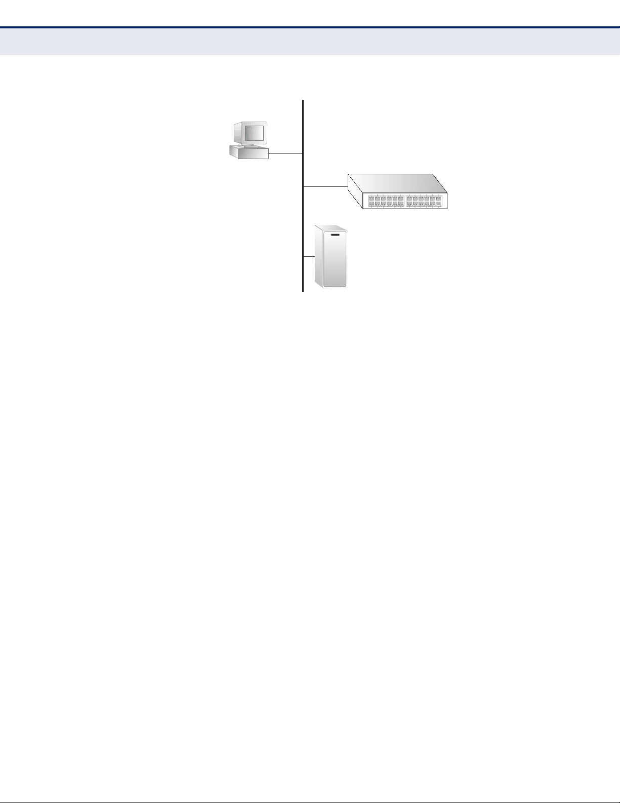
C
802.1x
client
RADIUS
server
1. Client attempts to access a switch port.
2. Switch sends client an identity request.
3. Client sends back identity information.
4. Switch forwards this to authentication server.
5. Authentication server challenges client.
6. Client responds with proper credentials.
7. Authentication server approves access.
8. Switch grants client access to this port.
HAPTER
Configuring Security
4
| Configuring the Switch
Figure 30: Using Port Security
This switch uses the Extensible Authentication Protocol over LANs (EAPOL)
to exchange authentication protocol messages with the client, and a
remote RADIUS authentication server to verify user identity and access
rights. These backend servers are configured on the AAA menu (see
page 117).
When a client (i.e., Supplicant) connects to a switch port, the switch (i.e.,
Authenticator) responds with an EAPOL identity request. The client
provides its identity (such as a user name) in an EAPOL response to the
switch, which it forwards to the RADIUS server. The RADIUS server verifies
the client identity and sends an access challenge back to the client. The
EAP packet from the RADIUS server contains not only the challenge, but
the authentication method to be used. The client can reject the
authentication method and request another, depending on the
configuration of the client software and the RADIUS server. The encryption
method used by IEEE 802.1X to pass authentication messages can be MD5
(Message-Digest 5), TLS (Transport Layer Security), PEAP (Protected
Extensible Authentication Protocol), or TTLS (Tunneled Transport Layer
Security). However, note that the only encryption method supported by
MAC-Based authentication is MD5. The client responds to the appropriate
method with its credentials, such as a password or certificate. The RADIUS
server verifies the client credentials and responds with an accept or reject
packet. If authentication is successful, the switch allows the client to
access the network. Otherwise, network access is denied and the port
remains blocked.
The operation of 802.1X on the switch requires the following:
◆ The switch must have an IP address assigned (see page 46).
◆ RADIUS authentication must be enabled on the switch and the IP
address of the RADIUS server specified. Backend RADIUS servers are
configured on the Authentication Configuration page (see page 117).
– 86 –
Page 87

C
HAPTER
4
| Configuring the Switch
Configuring Security
◆ 802.1X / MAC-based authentication must be enabled globally for the
switch.
◆ The Admin State for each switch port that requires client authentication
must be set to 802.1X or MAC-based.
◆ When using 802.1X authentication:
■
Each client that needs to be authenticated must have dot1x client
software installed and properly configured.
■
When using 802.1X authentication, the RADIUS server and 802.1X
client must support EAP. (The switch only supports EAPOL in order
to pass the EAP packets from the server to the client.)
■
The RADIUS server and client also have to support the same EAP
authentication type - MD5, PEAP, TLS, or TTLS. (Native support for
these encryption methods is provided in Windows 7, Windows Vista,
Windows XP, and in Windows 2000 with Service Pack 4. To support
these encryption methods in Windows 95 and 98, you can use the
AEGIS dot1x client or other comparable client software.)
MAC-based authentication allows for authentication of more than one user
on the same port, and does not require the user to have special 802.1X
software installed on his system. The switch uses the client's MAC address
to authenticate against the backend server. However, note that intruders
can create counterfeit MAC addresses, which makes MAC-based
authentication less secure than 802.1X authentication.
PATH
Advanced Configuration, Security, Network, NAS
USAGE GUIDELINES
When 802.1X is enabled, you need to configure the parameters for the
authentication process that runs between the client and the switch (i.e.,
authenticator), as well as the client identity lookup process that runs
between the switch and authentication server. These parameters are
described in this section.
PARAMETERS
These parameters are displayed:
System Configuration
◆ Mode - Indicates if 802.1X and MAC-based authentication are globally
enabled or disabled on the switch. If globally disabled, all ports are
allowed to forward frames.
◆ Reauthentication Enabled - Sets clients to be re-authenticated after
an interval specified by the Re-authentication Period. Re-authentication
can be used to detect if a new device is plugged into a switch port.
(Default: Disabled)
For MAC-based ports, reauthentication is only useful if the RADIUS
server configuration has changed. It does not involve communication
– 87 –
Page 88

C
HAPTER
Configuring Security
4
| Configuring the Switch
between the switch and the client, and therefore does not imply that a
client is still present on a port (see Age Period below).
◆ Reauthentication Period - Sets the time period after which a
connected client must be re-authenticated. (Range: 1-3600 seconds;
Default: 3600 seconds)
◆ EAPOL Timeout - Sets the time the switch waits for a supplicant
response during an authentication session before retransmitting a
Request Identify EAPOL packet. (Range: 1-255 seconds; Default: 30
seconds)
◆ Aging Period - The period used to calculate when to age out a client
allowed access to the switch through Single 802.1X, Multi 802.1X, and
MAC-based authentication as described below. (Range: 10-1000000
seconds; Default: 300 seconds)
When the NAS module uses the Port Security module to secure MAC
addresses, the Port Security module needs to check for activity on the
MAC address in question at regular intervals and free resources if no
activity is seen within the given age period.
If reauthentication is enabled and the port is in a 802.1X-based mode,
this is not so critical, since supplicants that are no longer attached to
the port will get removed upon the next reauthentication, which will
fail. But if reauthentication is not enabled, the only way to free
resources is by aging the entries.
For ports in MAC-based Auth. mode, reauthentication does not cause
direct communication between the switch and the client, so this will not
detect whether the client is still attached or not, and the only way to
free any resources is to age the entry.
◆ Hold Time - The time after an EAP Failure indication or RADIUS
timeout that a client is not allowed access. This setting applies to ports
running Single 802.1X, Multi 802.1X, or MAC-based authentication.
(Range: 10-1000000 seconds; Default: 10 seconds)
If the RADIUS server denies a client access, or a RADIUS server
request times out (according to the timeout specified on the AAA menu
on page 117), the client is put on hold in the Unauthorized state. In this
state, the hold timer does not count down during an on-going
authentication.
In MAC-based Authentication mode, the switch will ignore new frames
coming from the client during the hold time.
◆ RADIUS-Assigned QoS Enabled - RADIUS-assigned QoS provides a
means to centrally control the traffic class to which traffic coming from
a successfully authenticated supplicant is assigned on the switch. The
RADIUS server must be configured to transmit special RADIUS
attributes to take advantage of this feature.
The RADIUS-Assigned QoS Enabled checkbox provides a quick way to
globally enable/disable RADIUS-server assigned QoS Class
functionality. When checked, the individual port settings determine
– 88 –
Page 89

C
HAPTER
4
| Configuring the Switch
Configuring Security
whether RADIUS-assigned QoS Class is enabled for that port. When
unchecked, RADIUS-server assigned QoS Class is disabled for all ports.
When RADIUS-Assigned QoS is both globally enabled and enabled for a
given port, the switch reacts to QoS Class information carried in the
RADIUS Access-Accept packet transmitted by the RADIUS server when
a supplicant is successfully authenticated. If present and valid, traffic
received on the supplicant’s port will be classified to the given QoS
Class. If (re-)authentication fails or the RADIUS Access-Accept packet
no longer carries a QoS Class or it's invalid, or the supplicant is
otherwise no longer present on the port, the port's QoS Class is
immediately reverted to the original QoS Class (which may be changed
by the administrator in the meanwhile without affecting the RADIUSassigned setting).
This option is only available for single-client modes, i.e. port-based
802.1X and Single 802.1X.
RADIUS Attributes Used in Identifying a QoS Class
The User-Priority-Table attribute defined in RFC4675 forms the basis for
identifying the QoS Class in an Access-Accept packet.
Only the first occurrence of the attribute in the packet will be
considered. To be valid, all 8 octets in the attribute's value must be
identical and consist of ASCII characters in the range '0' - '3', which
translates into the desired QoS Class in the range 0-3.
QoS assignments to be applied to a switch port for an authenticated
user may be configured on the RADIUS server as described below:
■
The “Filter-ID” attribute (attribute 11) can be configured on the
RADIUS server to pass the following QoS information:
Table 7: Dynamic QoS Profiles
Profile Attribute Syntax Example
DiffServ service-policy-in=policy-map-name service-policy-in=p1
Rate Limit rate-limit-input=rate rate-limit-input=100
802.1p switchport-priority-default=value switchport-priority-default=2
■
Multiple profiles can be specified in the Filter-ID attribute by using a
(in units of Kbps)
semicolon to separate each profile.
For example, the attribute “service-policy-in=pp1;rate-limitinput=100” specifies that the diffserv profile name is “pp1,” and the
ingress rate limit profile value is 100 kbps.
■
If duplicate profiles are passed in the Filter-ID attribute, then only
the first profile is used.
For example, if the attribute is “service-policy-in=p1;service-policyin=p2”, then the switch applies only the DiffServ profile “p1.”
■
Any unsupported profiles in the Filter-ID attribute are ignored.
– 89 –
Page 90

C
HAPTER
Configuring Security
4
| Configuring the Switch
For example, if the attribute is “map-ip-dscp=2:3;service-policyin=p1,” then the switch ignores the “map-ip-dscp” profile.
■
When authentication is successful, the dynamic QoS information
may not be passed from the RADIUS server due to one of the
following conditions (authentication result remains unchanged):
■
The Filter-ID attribute cannot be found to carry the user profile.
■
The Filter-ID attribute is empty.
■
The Filter-ID attribute format for dynamic QoS assignment is
unrecognizable (can not recognize the whole Filter-ID attribute).
■
Dynamic QoS assignment fails and the authentication result
changes from success to failure when the following conditions
occur:
■
Illegal characters found in a profile value (for example, a nondigital character in an 802.1p profile value).
■
Failure to configure the received profiles on the authenticated
port.
■
When the last user logs off on a port with a dynamic QoS
assignment, the switch restores the original QoS configuration for
the port.
■
When a user attempts to log into the network with a returned
dynamic QoS profile that is different from users already logged on
to the same port, the user is denied access.
■
While a port has an assigned dynamic QoS profile, any manual QoS
configuration changes only take effect after all users have logged
off the port.
◆ RADIUS-Assigned VLAN Enabled - RADIUS-assigned VLAN provides
a means to centrally control the VLAN on which a successfully
authenticated supplicant is placed on the switch. Incoming traffic will
be classified to and switched on the RADIUS-assigned VLAN. The
RADIUS server must be configured to transmit special RADIUS
attributes to take advantage of this feature.
The “RADIUS-Assigned VLAN Enabled” checkbox provides a quick way
to globally enable/disable RADIUS-server assigned VLAN functionality.
When checked, the individual port settings determine whether RADIUSassigned VLAN is enabled for that port. When unchecked, RADIUSserver assigned VLAN is disabled for all ports.
When RADIUS-Assigned VLAN is both globally enabled and enabled for
a given port, the switch reacts to VLAN ID information carried in the
RADIUS Access-Accept packet transmitted by the RADIUS server when
a supplicant is successfully authenticated. If present and valid, the
port's Port VLAN ID will be changed to this VLAN ID, the port will be set
to be a member of that VLAN ID, and the port will be forced into VLANunaware mode. Once assigned, all traffic arriving on the port will be
classified and switched on the RADIUS-assigned VLAN ID.
– 90 –
Page 91

C
HAPTER
4
| Configuring the Switch
Configuring Security
If (re-)authentication fails or the RADIUS Access-Accept packet no
longer carries a VLAN ID or it's invalid, or the supplicant is otherwise no
longer present on the port, the port's VLAN ID is immediately reverted
to the original VLAN ID (which may be changed by the administrator in
the meanwhile without affecting the RADIUS-assigned setting).
This option is only available for single-client modes, i.e. port-based
802.1X and Single 802.1X.
N
OTE
:
For trouble-shooting VLAN assignments, use the Monitor > VLANs >
VLAN Membership and VLAN Port pages. These pages show which modules
have (temporarily) overridden the current Port VLAN configuration.
RADIUS Attributes Used in Identifying a VLAN ID
RFC 2868 and RFC 3580 form the basis for the attributes used in
identifying a VLAN ID in an Access-Accept packet. The following criteria
are used:
■
The Tunnel-Medium-Type, Tunnel-Type, and Tunnel-Private-GroupID attributes must all be present at least once in the Access-Accept
packet.
■
The switch looks for the first set of these attributes that have the
same Tag value and fulfil the following requirements (if Tag == 0 is
used, the Tunnel-Private-Group-ID does not need to include a Tag):
■
Value of Tunnel-Medium-Type must be set to “IEEE-802” (ordinal
6).
■
Value of Tunnel-Type must be set to “VLAN” (ordinal 13).
■
Value of Tunnel-Private-Group-ID must be a string of ASCII
characters in the range 0-9, which is interpreted as a decimal
string representing the VLAN ID. Leading '0's are discarded. The
final value must be in the range 1-4095.
The VLAN list can contain multiple VLAN identifiers in the format
“1u,2t,3u” where “u” indicates an untagged VLAN and “t” a
tagged VLAN.
◆ Guest VLAN Enabled - A Guest VLAN is a special VLAN - typically with
limited network access - on which 802.1X-unaware clients are placed
after a network administrator-defined timeout. The switch follows a set
of rules for entering and leaving the Guest VLAN as listed below.
The “Guest VLAN Enabled” checkbox provides a quick way to globally
enable/disable Guest VLAN functionality. When checked, the individual
port settings determine whether the port can be moved into Guest
VLAN. When unchecked, the ability to move to the Guest VLAN is
disabled for all ports.
When Guest VLAN is both globally enabled and enabled for a given
port, the switch considers moving the port into the Guest VLAN
according to the rules outlined below. This option is only available for
EAPOL-based modes, i.e. Port-based 802.1X, Single 802.1X, and Multi
802.1X
– 91 –
Page 92

C
HAPTER
Configuring Security
4
| Configuring the Switch
N
OTE
:
For trouble-shooting VLAN assignments, use the Monitor > VLANs >
VLAN Membership and VLAN Port pages. These pages show which modules
have (temporarily) overridden the current Port VLAN configuration.
Guest VLAN Operation
When a Guest VLAN enabled port's link comes up, the switch starts
transmitting EAPOL Request Identity frames. If the number of
transmissions of such frames exceeds Max. Reauth. Count and no
EAPOL frames have been received in the meanwhile, the switch
considers entering the Guest VLAN. The interval between transmission
of EAPOL Request Identity frames is configured with EAPOL Timeout. If
Allow Guest VLAN if EAPOL Seen is enabled, the port will now be placed
in the Guest VLAN. If disabled, the switch will first check its history to
see if an EAPOL frame has previously been received on the port (this
history is cleared if the port link goes down or the port's Admin State is
changed), and if not, the port will be placed in the Guest VLAN.
Otherwise it will not move to the Guest VLAN, but continue transmitting
EAPOL Request Identity frames at the rate given by EAPOL Timeout.
Once in the Guest VLAN, the port is considered authenticated, and all
attached clients on the port are allowed access on this VLAN. The
switch will not transmit an EAPOL Success frame after entering the
Guest VLAN.
While in the Guest VLAN, the switch monitors the link for EAPOL
frames, and if one such frame is received, the switch immediately takes
the port out of the Guest VLAN and starts authenticating the supplicant
according to the port mode. If an EAPOL frame is received, the port will
never be able to go back into the Guest VLAN if the “Allow Guest VLAN
if EAPOL Seen” is disabled.
◆ Guest VLAN ID - This is the value that a port's Port VLAN ID is set to if
a port is moved into the Guest VLAN. It is only changeable if the Guest
VLAN option is globally enabled. (Range: 1-4095)
◆ Max. Reauth. Count - The number of times that the switch transmits
an EAPOL Request Identity frame without receiving a response before
adding a port to the Guest VLAN. The value can only be changed if the
Guest VLAN option is globally enabled. (Range: 1-255)
◆ Allow Guest VLAN if EAPOL Seen - The switch remembers if an
EAPOL frame has been received on the port for the lifetime of the port.
Once the switch considers whether to enter the Guest VLAN, it will first
check if this option is enabled or disabled. If disabled (the default), the
switch will only enter the Guest VLAN if an EAPOL frame has not been
received on the port for the lifetime of the port. If enabled, the switch
will consider entering the Guest VLAN even if an EAPOL frame has been
received on the port for the lifetime of the port. The value can only be
changed if the Guest VLAN option is globally enabled.
Port Configuration
◆ Port – Port identifier.
– 92 –
Page 93

C
HAPTER
4
| Configuring the Switch
Configuring Security
◆ Admin State - If NAS is globally enabled, this selection controls the
port's authentication mode. The following modes are available:
■
Force Authorized - The switch sends one EAPOL Success frame
when the port link comes up. This forces the port to grant access to
all clients, either dot1x-aware or otherwise. (This is the default
setting.)
■
Force Unauthorized - The switch will send one EAPOL Failure
frame when the port link comes up. This forces the port to deny
access to all clients, either dot1x-aware or otherwise.
■
Port-based 802.1X - Requires a dot1x-aware client to be
authorized by the authentication server. Clients that are not dot1xaware will be denied access.
■
Single 802.1X - At most one supplicant can get authenticated on
the port at a time. If more than one supplicant is connected to a
port, the one that comes first when the port's link comes up will be
the first one considered. If that supplicant doesn't provide valid
credentials within a certain amount of time, another supplicant will
get a chance. Once a supplicant is successfully authenticated, only
that supplicant will be allowed access. This is the most secure of all
the supported modes. In this mode, the Port Security module is
used to secure a supplicant's MAC address once successfully
authenticated.
■
Multi 802.1X - One or more supplicants can get authenticated on
the same port at the same time. Each supplicant is authenticated
individually and secured in the MAC table using the Port Security
module.
In Multi 802.1X it is not possible to use the multicast BPDU MAC
address as the destination MAC address for EAPOL frames sent from
the switch towards the supplicant, since that would cause all
supplicants attached to the port to reply to requests sent from the
switch. Instead, the switch uses the supplicant's MAC address,
which is obtained from the first EAPOL Start or EAPOL Response
Identity frame sent by the supplicant. An exception to this is when
no supplicants are attached. In this case, the switch sends EAPOL
Request Identity frames using the BPDU multicast MAC address as
the destination - to wake up any supplicants that might be on the
port.
The maximum number of supplicants that can be attached to a port
can be limited using the Port Security Limit Control functionality.
■
MAC-based Auth. - Enables MAC-based authentication on the port.
The switch does not transmit or accept EAPOL frames on the port.
Flooded frames and broadcast traffic will be transmitted on the port,
whether or not clients are authenticated on the port, whereas
unicast traffic from an unsuccessfully authenticated client will be
dropped. Clients that are not (or not yet) successfully authenticated
will not be allowed to transmit frames of any kind.
The switch acts as the supplicant on behalf of clients. The initial
frame (any kind of frame) sent by a client is snooped by the switch,
which in turn uses the client's MAC address as both user name and
– 93 –
Page 94

C
HAPTER
Configuring Security
4
| Configuring the Switch
password in the subsequent EAP exchange with the RADIUS server.
The 6-byte MAC address is converted to a string on the following
form “xx-xx-xx-xx-xx-xx”, that is, a dash (-) is used as separator
between the lower-cased hexadecimal digits. The switch only
supports the MD5-Challenge authentication method, so the RADIUS
server must be configured accordingly.
When authentication is complete, the RADIUS server sends a
success or failure indication, which in turn causes the switch to open
up or block traffic for that particular client, using the Port Security
module. Only then will frames from the client be forwarded on the
switch. There are no EAPOL frames involved in this authentication,
and therefore, MAC-based Authentication has nothing to do with the
802.1X standard.
The advantage of MAC-based authentication over port-based
802.1X is that several clients can be connected to the same port
(e.g. through a 3rd party switch or a hub) and still require individual
authentication, and that the clients don't need special supplicant
software to authenticate. The advantage of MAC-based
authentication over 802.1X-based authentication is that the clients
don't need special supplicant software to authenticate. The
disadvantage is that MAC addresses can be spoofed by malicious
users - equipment whose MAC address is a valid RADIUS user can
be used by anyone. Also, only the MD5-Challenge method is
supported. The maximum number of clients that can be attached to
a port can be limited using the Port Security Limit Control
functionality.
Further Guidelines for Port Admin State
■
Port Admin state can only be set to Force-Authorized for ports
participating in the Spanning Tree algorithm (see page 135).
■
When 802.1X authentication is enabled on a port, the MAC address
learning function for this interface is disabled, and the addresses
dynamically learned on this port are removed from the common
address table.
■
Authenticated MAC addresses are stored as dynamic entries in the
switch's secure MAC address table. Configured static MAC addresses
are added to the secure address table when seen on a switch port
(see page 171). Static addresses are treated as authenticated
without sending a request to a RADIUS server.
■
When port status changes to down, all MAC addresses are cleared
from the secure MAC address table. Static VLAN assignments are
not restored.
◆ RADIUS-Assigned QoS Enabled - Enables or disables this feature for
a given port. Refer to the description of this feature under the System
Configuration section.
◆ RADIUS-Assigned VLAN Enabled - Enables or disables this feature
for a given port. Refer to the description of this feature under the
System Configuration section.
– 94 –
Page 95

C
HAPTER
4
| Configuring the Switch
Configuring Security
◆ Guest VLAN Enabled - Enables or disables this feature for a given
port. Refer to the description of this feature under the System
Configure section.
◆ Port State - The current state of the port:
■
Globally Disabled - 802.1X and MAC-based authentication are
globally disabled. (This is the default state.)
■
Link Down - 802.1X or MAC-based authentication is enabled, but
there is no link on the port.
■
Authorized - The port is in Force Authorized mode, or a singlesupplicant mode and the supplicant is authorized.
■
Unauthorized - The port is in Force Unauthorized mode, or a
single-supplicant mode and the supplicant is not successfully
authorized by the RADIUS server.
■
X Auth/Y Unauth - The port is in a multi-supplicant mode. X
clients are currently authorized and Y are unauthorized.
◆ Restart - Restarts client authentication using one of the methods
described below. Note that the restart buttons are only enabled when
the switch’s authentication mode is globally enabled (under System
Configuration) and the port's Admin State is an EAPOL-based or MACBased mode. Clicking these buttons will not cause settings changed on
the page to take effect.
■
Reauthenticate - Schedules reauthentication to whenever the
quiet-period of the port runs out (EAPOL-based authentication). For
MAC-based authentication, reauthentication will be attempted
immediately. The button only has effect for successfully
authenticated clients on the port and will not cause the clients to
get temporarily unauthorized.
■
Reinitialize - Forces a reinitialization of the clients on the port and
thereby a reauthentication immediately. The clients will transfer to
the unauthorized state while the reauthentication is in progress.
WEB INTERFACE
To configure 802.1X Port Security:
1. Click Advanced Configuration, Security, Network, NAS.
2. Modify the required attributes.
3. Click Save.
– 95 –
Page 96
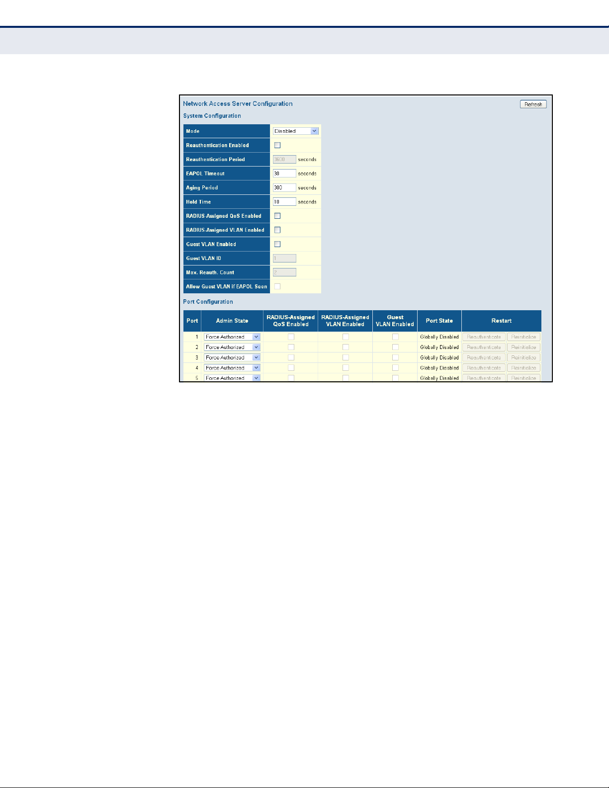
C
HAPTER
Configuring Security
4
| Configuring the Switch
Figure 31: Network Access Server Configuration
FILTERING TRAFFIC
WITH ACCESS
CONTROL LISTS
An Access Control List (ACL) is a sequential list of permit or deny
conditions that apply to IP addresses, MAC addresses, or other more
specific criteria. This switch tests ingress packets against the conditions in
an ACL one by one. A packet will be accepted as soon as it matches a
permit rule, or dropped as soon as it matches a deny rule. If no rules
match, the frame is accepted. Other actions can also be invoked when a
matching packet is found, including rate limiting, copying matching packets
to another port or to the system log, or shutting down a port.
ASSIGNING ACL POLICIES AND RESPONSES
Use the ACL Port Configuration page to define a port to which matching
frames are copied, enable logging, or shut down a port when a matching
frame is seen. Note that rate limiting (configured with the Rate Limiter
menu, page 98) is implemented regardless of whether or not a matching
packet is seen.
PATH
Advanced Configuration, Security, Network, ACL, Ports
PARAMETERS
These parameters are displayed:
◆ Port - Port Identifier.
– 96 –
Page 97

C
HAPTER
4
| Configuring the Switch
Configuring Security
◆ Policy ID - An ACL policy configured on the ACE Configuration page
(page 101). (Range: 1-8; Default: 1, which is undefined)
◆ Action - Permits or denies a frame based on whether it matches a rule
defined in the assigned policy. (Default: Permit)
◆ Rate Limiter ID - Specifies a rate limiter (page 98) to apply to the
port. (Range: 1-15; Default: Disabled)
◆ Port Redirect - Defines a port to which matching frames are re-
directed. (Range: 1-28; Default: Disabled)
To use this function, Action must be set to Deny for the local port.
◆ Mirror - Mirrors matching frames from this port. (Default: Disabled)
To use this function, the destination port to which traffic is mirrored
must be configured on the Mirror Configuration page (see "Configuring
Local Port Mirroring" on page 208).
ACL-based port mirroring set by this parameter and port mirroring set
on the general Mirror Configuration page are implemented
independently. To use ACL-based mirroring, enable the Mirror
parameter on the ACL Ports Configuration page. Then open the Mirror
Configuration page, set the “Port to mirror on” field to the required
destination port, and leave the “Mode” field Disabled.
◆ Logging - Enables logging of matching frames to the system log.
(Default: Disabled)
Open the System Log Information menu (page 223) to view any entries
stored in the system log for this entry. Related entries will be displayed
under the “Info” or “All” logging levels.
◆ Shutdown - Shuts down a port when a macthing frame is seen.
(Default: Disabled)
◆ State - Specify the port state:
■
Enabled - To reopen ports by changing the port configuration in the
ACL configuration pages. (This is the default.)
■
Disabled - To close ports by changing the volatile port
configuration of the ACL user module.
◆ Counter - The number of frames which have matched any of the rules
defined in the selected policy.
WEB INTERFACE
To configure ACL policies and responses for a port:
1. Click Advanced Configuration, Security, Network, ACL, Ports.
2. Assign an ACL policy configured on the ACE Configuration page, specify
the responses to invoke when a matching frame is seen, including the
filter mode, copying matching frames to another port, logging matching
– 97 –
Page 98
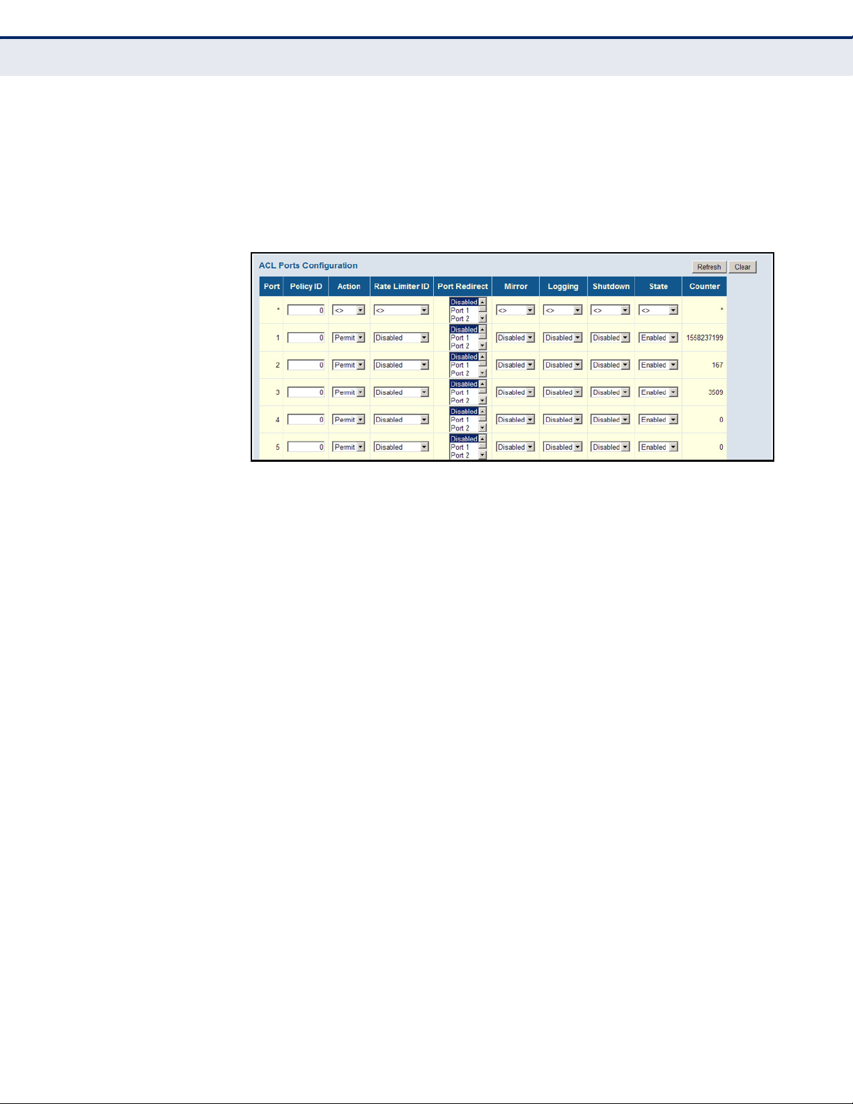
C
HAPTER
Configuring Security
4
| Configuring the Switch
frames, or shutting down the port. Note that the setting for rate limiting
is implemented regardless of whether or not a matching packet is seen.
3. Repeat the preceding step for each port to which an ACL will be applied.
4. Click Save.
Figure 32: ACL Port Configuration
CONFIGURING RATE LIMITERS
Use the ACL Rate Limiter Configuration page to define the rate limits
applied to a port (as configured either through the ACL Ports Configuration
menu (page 96) or the Access Control List Configuration menu (page 99).
PATH
Advanced Configuration, Security, Network, ACL, Rate Limiters
PARAMETERS
These parameters are displayed:
◆ Rate Limiter ID - Rate limiter identifier. (Range: 0-14; Default: 1)
◆ Rate - The threshold above which packets are dropped.
(Options: 0-100 pps, or 0, 100, 2*100, 3*100, ... 1000000 kbps)
Due to an ASIC limitation, the enforced rate limits are slightly less than
the listed options. For example: 1 Kpps translates into an enforced
threshold of 1002.1 pps.
◆ Unit - Unit of measure. (Options: pps or kbps; Default: pps)
WEB INTERFACE
To configure rate limits which can be applied to a port:
1. Click Advanced Configuration, Security, Network, ACL, Rate Limiters.
2. For any of the rate limiters, select the maximum ingress rate that will
be supported on a port once a match has been found in an assigned
ACL.
– 98 –
Page 99
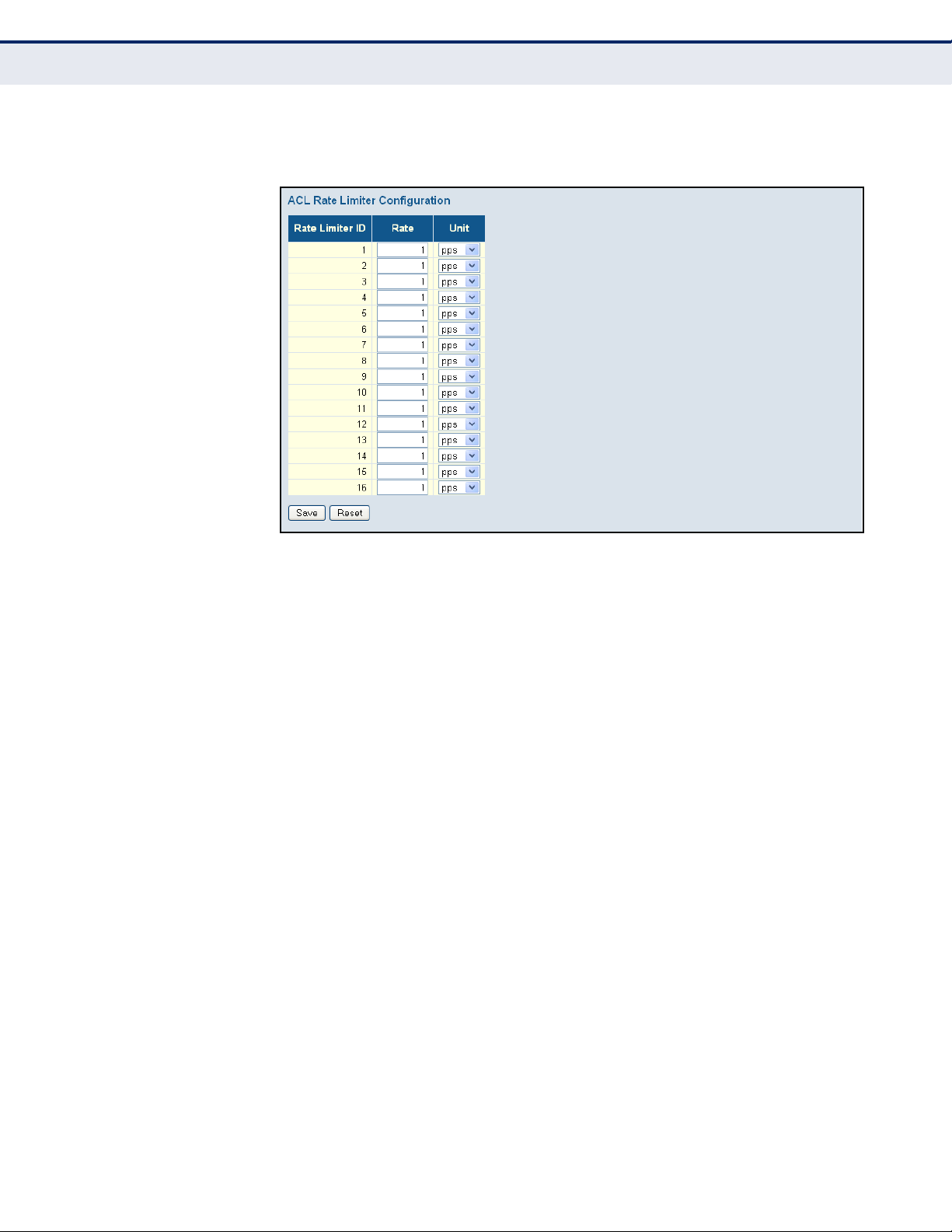
C
HAPTER
3. Click Save.
Figure 33: ACL Rate Limiter Configuration
4
| Configuring the Switch
Configuring Security
CONFIGURING ACCESS CONTROL LISTS
Use the Access Control List Configuration page to define filtering rules for
an ACL policy, for a specific port, or for all ports. Rules applied to a port
take effect immediately, while those defined for a policy must be mapped
to one or more ports using the ACL Ports Configuration menu (page 96).
PATH
Advanced Configuration, Security, Network, ACL, Access Control List
USAGE GUIDELINES
◆ Rules within an ACL are checked in the configured order, from top to
bottom. A packet will be accepted as soon as it matches a permit rule,
or dropped as soon as it matches a deny rule. If no rules match, the
frame is accepted.
◆ The maximum number of ACL rules that can be configured on the
switch is 128.
◆ The maximum number of ACL rules that can be bound to a port is 10.
◆ ACLs provide frame filtering based on any of the following criteria:
■
Any frame type (based on MAC address, VLAN ID, VLAN priority)
■
Ethernet type (based on Ethernet type value, MAC address, VLAN
ID, VLAN priority)
■
ARP (based on ARP/RARP type, request/reply, sender/target IP,
hardware address matches ARP/RARP MAC address, ARP/RARP
hardware address length matches protocol address length, matches
– 99 –
Page 100

C
HAPTER
Configuring Security
4
| Configuring the Switch
this entry when ARP/RARP hardware address is equal to Ethernet,
matches this entry when ARP/RARP protocol address space setting
is equal to IP (0x800)
■
IPv4 frames (based on destination MAC address, protocol type, TTL,
IP fragment, IP option flag, source/destination IP, VLAN ID, VLAN
priority)
PARAMETERS
These parameters are displayed:
ACCESS CONTROL LIST CONFIGURATION
◆ Ingress Port - The ingress port of the ACE:
■
All - The ACE will match all ingress ports.
■
Port - The ACE will match a specific ingress port.
◆ Policy / Bitmask - The policy number and bitmask of the ACE.
◆ Frame Type - The type of frame to match.
◆ Action - Shows whether a frame is permitted or denied when it
matches an ACL rule.
◆ Rate Limiter - Shows if rate limiting will be enabled or disabled when
matching frames are found.
◆ Port Redirect - Port to which frames matching the ACE are redirected.
◆ Mirror - Mirrors matching frames from this port. (Default: Disabled)
See "Configuring Local Port Mirroring" on page 208.
◆ Counter - Shows he number of frames which have matched any of the
rules defined for this ACL.
The following buttons are used to edit or move the ACL entry (ACE):
Table 8: QCE Modification Buttons
Button Description
Inserts a new ACE before the current row.
Edits the ACE.
Moves the ACE up the list.
Moves the ACE down the list.
Deletes the ACE.
The lowest plus sign adds a new entry at the bottom of the list.
– 100 –
 Loading...