

SMC Networks SMCGB10-Z User Manual
Copyright ©2013 SMC Networks Page 1
All Rights Reserved
I/M SMCGB10-Z rev. 1.0
8/2/2013
1 Product Introduction
The SMCGB10-Z is a wireless Glass Break
Detector that complies with the ANSI/UL 639
standard for Intrusion products. It is intended for
residential indoor dwelling unit applications and
other areas approved by the authority having
jurisdiction (AHJ). It is not intended for use in
industrial applications.
The SMCGB10-Z operates with your wireless
Touchscreen, providing a local indication. Refer
to the Touchscreen installation instructions for
revision verification details.
2 Parts List
Your SMCGB10-Z package comes with:
One SMCGB10-Z Glass Break Detector
One CR123 Lithium battery
Mounting screws and anchors
This User Guide
3 Finding a Suitable Location
The SMCGB10-Z must always be in direct line of
sight of all windows to be protected. The
SMCGB10-Z cannot consistently detect glass
breaking around corners or in other rooms. There
is no required front, back, up or down
orientation.
Wall Mount
The best wall-mount location is on the opposite
wall, assuming the glass to be protected is within
the sensor's range and line of sight. The
adjoining wall can also be used.
Ceiling Mount
Mount the SMCGB10-Z in a location that has a
direct line of sight of the glass to be protected.
Since sound travels directionally out from a
broken window, a position 8 ft. (2.4 m) into the
room provides better detection.
To determine the best mounting location, mount
the SMCGB10-Z:
At least 3.3 ft. (1 m) from the windows being
protected and at least 4 ft. (1.2 m) from
noise sources such as TVs, speakers, sinks,
and doors.
In the direct line of sight of the glass to be
protected.
In a suitable environment: temperature
between 0 and 120°F (-18 and 50°C); and
humidity between 10 and 90% noncondensing.
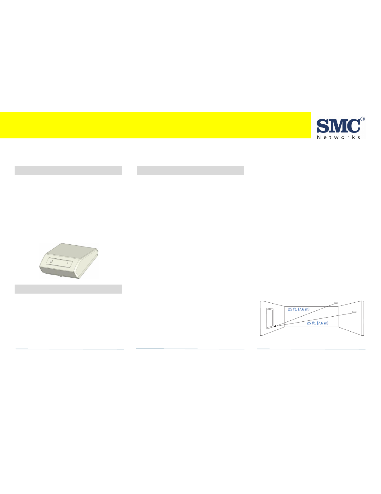
On a stable surface up to 25 ft. (7.6 m) from
the farthest point on the glass surface.
Recommended Locations and Range
The SMCGB10-Z is omni-directional, providing
360° coverage. Coverage is measured from the
SMCGB10-Z to the point on the glass farthest
from the sensor. The sensor can be mounted as
close as 3.3 ft. (1 m) from the glass. The
maximum range depends on the type of glass
being protected:
Armor-coated glass: Mount the SMCGB10-Z no
more than 12 ft. (3.6 m) from the glass.
Plate, tempered, laminated, and wired glass:
Mount the SMCGB10-Z on the ceiling or the
opposite or adjoining wall. Maximum range is
25 ft. (7.6 m).
SMCGB10-Z G l a s s Break Sens o r G u ide
Congratulations on purchasing your SMCGB10-Z Glass Break Sensor.
The SMCGB10-Z Glass Break Sensor provides excellent acoustic sensing by listening to actual patterns of breaking glass across the full audio band
while providing immunity to false alarm. This Quick Start Guide has all the information to get your SMC Glass Break Sensor up and running.
SMCGB10-Z Glass Break Sensor Guide
Copyright ©2013 SMC Networks Page 2
All Rights Reserved
I/M SMCGB10-Z rev. 1.0
8/2/2013
Locations to Avoid
Improper location can affect the sensitive
electronic components in this product. To avoid
causing damage to the product, to provide
optimum performance, and to prevent
unnecessary nuisance alarms:
Avoid rooms smaller than 10 x 10 ft. (3m x
3m).
Avoid locations where lined, insulating, or
sound-deadening drapes or closed wooden
shutters are used.
Avoid the corner of a room.
Do not install the SMCGB10-Z in humid
rooms. Excess moisture on the circuit board
can cause a short and a false alarm.
Avoid locations that expose the SMCGB10-Z
to possible false alarm sources such as:
- Glass airlocks and vestibule areas
- Kitchens
- Corner mounting
- Residential car garages
- Small utility rooms
- Stairwells
- Bathrooms
- Small acoustically live rooms.
- Locations exposed to white noise, such as
air compressors.
4 Mounting the Sensor
You can mount the SMCGB10-Z on a wall or
ceiling.
A. Disconnect alarm-notification appliances,
service-release devices, and extinguishing
systems. Test communications between the
Touchscreen and the product before
permanently mounting as follows:
- Hold the SMCGB10-Z where you plan to
install it.
- Hold the glass break tester next to the glass
break’s microphone sensor and press the test
button on the glass break tester. The product
sends a signal to the Touchscreen.
- At the Touchscreen, verify the signal was
received and RF signal strength is adequate.
If no signal is received or the RF signal is low,
relocate the product and retest.
B. Using two supplied screws and anchors,
mount the base of the product as follows:
- Remove the screw located in the front.
- Remove the top cover using a flat bladed
tool in the screw location to pry open the
top cover.
- Find the mounting location and drill holes
in the base per the mounting impression in
the base.
- Use the anchors and screws to secure the
product to the mounting surface.
C. Replace the SMCGB10-Z top cover:
- Snap the top onto the base.
- Replace the screw into the front location.
5 Basic Operation
The SMCGB10-Z is equipped with an intuitive
normal mode operation. Since the batteries are
pre-installed, remove the battery pull tab to
turn ON power. The SMCGB10-Z searches for a
networked Touchscreen with which to pair.
During this Search Mode time, the RF wireless
module transmits every ~ 5-seconds.
Not pairing or enrolling into a Touchscreen
within minutes of initial power up places a large
drain the batteries.
Failure to complete pairing results in dead
batteries after 2-3 days pass.
SMCGB10-Z Glass Break Sensor Guide
Copyright ©2013 SMC Networks Page 3
All Rights Reserved
I/M SMCGB10-Z rev. 1.0
8/2/2013
Normal Mode Operation
In normal operation, the red LED is OFF.
In wake up, the red LED flashes ON with two
quick flashes.
In alarm mode, the red LED stays ON for 4
seconds. Sends an alarm message to the
Touchscreen.
In trouble or maintenance mode, the red LED
does not activate after a wake up test.
In low battery mode, a message is sent to the
Touchscreen.
Note: Modes can be viewed from the
Touchscreen.
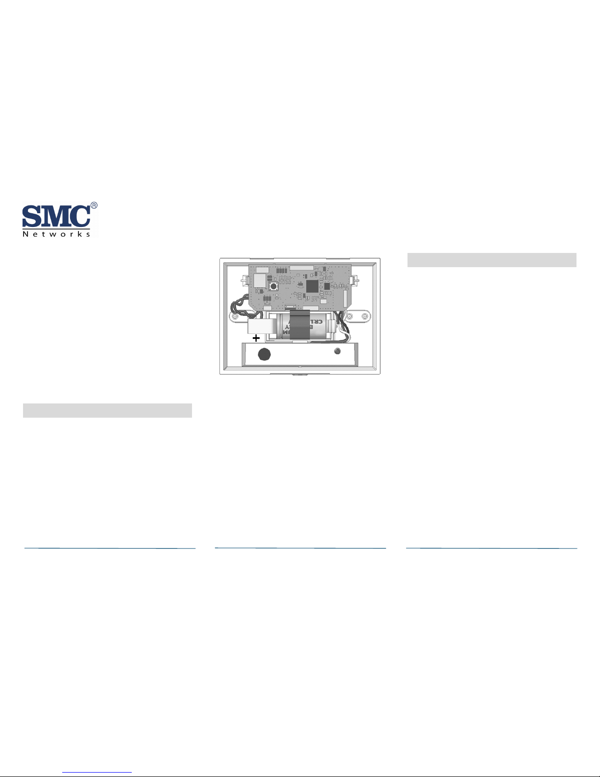
6 Installing/Replacing Battery
The SMCGB10-Z comes with one battery
preinstalled. When you need to replace the
battery, use the following procedure.
Note: Place the Touchscreen into sensor test
mode prior to replacing the batteries. Otherwise,
an alarm/tamper condition may be indicated.
A. Remove the product top cover.
B. If replacing the battery, remove the old
battery and properly dispose of it as
recommended by the battery manufacturer.
C. Install the new battery. Note the polarity
illustration in the battery compartment.
C. Replace the top cover.
D. Replace the front screw.
When replacing the battery, use one of the
following approved brands:
Duracell Ultra
Panasonic
Note: Using a different battery may have a
detrimental effect on the product's operation.
Constant exposures to high or low humidity may
reduce battery life.
After installing or changing the batteries,
reinstall the SMCGB10-Z top cover. Test your
SMCGB10-Z using a wake-up test.
7 Adding to Touchscreen
Each SMCGB10-Z is programmed with a unique ID
when manufactured. The unique ID is enrolled
into the Touchscreen at the time of installation,
allowing the SMCGB10-Z to communicate with
that specific Touchscreen.
A. Log in to the Settings app with an Installer
code.
B. In the Settings menu, tap Sensors & Zones >
Add a Sensor/Zone.
C. Place the SMCGB10-Z in Search mode and
prepare it to be added to the Touchscreen
(refer to the installation documentation for
your sensors). Available sensors meet the
following requirements:
- Defaulted.
- Not currently paired with another
Touchscreen device.
- Currently in Search mode.
D. At the Locating Wireless Sensors screen, tap
Next. A Done button appears on the screen
and the Touchscreen searches for sensors
that are available to be added. As sensors
are found, a grayed icon appears for that
sensor.
E. Fault each found sensor to pair it to the
Touchscreen. The icon for each sensor is
undarkened as it is faulted and the
Touchscreen beeps. The sensor is paired to
the Touchscreen.
 Loading...