

SMC Networks SMCCO02-Z User Manual

SMCCO02-Z Carbon Monoxide Alarm User Guide
Copyright
©
2011 SMC Networks Page 1
All Rights Reserved
I/M SMCWK01-Z rev. 1.0
4/19/11
Product Introduction
The SMCCO02-Z Is a wireless carbon monoxide (CO) alarm that monitors the levels of CO gas and provides early warning when potentially
dangerous levels exist. The SMCCO02-Z uses patented and field-proven electrochemical sensor technology. If a dangerous concentration of CO
is detected by patented and field-proven electrochemical sensor:
¾ An LED indicator on the SMCCO02-Z goes ON.
¾ An internal siren sounds in temporal 4 pattern.
¾ The SMCCO02-Z sends alarm signal to the control panel within 15 seconds of detecting dangerous concentration of CO gas. The control
panel activates its internal siren and reports the alarm condition to the central monitoring station if the system is monitored.
The SMCCO02-Z also detects low battery, wall tamper, and sensor end-of-life. These trouble codes are sent to the control panel, which reports
the condition to the central monitoring station. The alarm automatically resets when CO is no longer detected. The SMCCO02-Z does not
detect fire, smoke, or any other gas.
TheSMCCO02-Z is listed and complies with the ANSI/UL 2034 standard for CO alarms. It is intended for residential indoor dwelling unit
applications and other areas approved by the authority having jurisdiction (AHJ). It is not intended for use in industrial applications.
To help identify the date to replace the alarm, an area has been reserved on the side of the alarm. Write the “replace by” date (seven years
from power up) with a permanent marker in the area provided.
WARNING: After seven years from initial power up, this alarm beeps two times every 30 seconds to indicate it is time to replace the alarm.
Replace the alarm immediately because it will not detect CO in this condition.
About This Guide
This User Guide describes how to install your SMCCO02-Z. Notice that we refer to this document as a User Guide. This is because our intention
is for you use this guide just as you will be using your SMCCO02-Z. Keep this guide in a handy location and refer to it when you have questions
about your SMCCO02-Z , its functions and features, or if you have questions about carbon monoxide. Reading this guide is the only way to learn
how to use your SMCCO02-Z wisely and to know how to react in the event of an alarm.
SMCCO02-Z C e
Copyright
©
2011 SMC Networks Page 2
All Rights Reserved
O Alarm User Guid
¾ In dead-air spaces, such as peaks of
vaulted ceilings or gabled roofs,
where CO might not reach the
sensor in time to provide early
warning.
¾ Near deep-cell large batteries.
Large batteries have emissions that
can cause the alarm to perform at
less than optimum performance.
¾ Where drapes, furniture, or other
objects block the flow of air to the
vents.
¾ Near ceiling fans, doors, windows,
or areas directly exposed to the
weather.
¾ In areas with a large quantity of
metal or electrical wires.
¾ In areas that obstruct the vents
located on the alarm.
Selecting an improper location can affect
the sensitive electronic components in
your SMCCO02-Z. To avoid damaging the
unit, to provide optimum performance,
and to prevent unnecessary nuisance
alarms, do not install the SMCCO02-Z:
¾ In kitchens, garages, or furnace
rooms that can expose the sensor to
substances that can damage or
contaminate it.
¾ Near vents, flues, chimneys, or any
forced/unforced air ventilation
openings.
¾ Within 5 feet of heating or cooking
appliances. We recommend 15 feet
to prevent nuisance alarms.
¾ In areas where the temperature is
colder than 40°F (4.4°C) or hotter
than 100°F (37.8°C) such as crawl
spaces, attics, porches, and
garages.
¾ On metal surfaces.
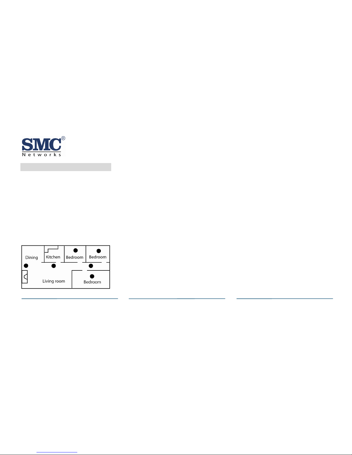
When choosing installation locations, be
sure you can hear the alarm from all
sleeping areas. If you install only one
alarm in your home, install it near bedrooms, not in the basement or furnace
room. Place the alarm out of reach of
children. Under no circumstances should
children be allowed to handle the alarm.
Mount the SMCCO02-Z alarms in or near
bedrooms and living areas. We recommend you install an alarm on each level
of your home.
1
Mounting Guidelines
Figure 1. Recommended Locations
I/M SMCWK01-Z rev. 1.0
4/19/11
SMCCO02-Z CO Alarm User Guide
B. Insert the supplied two screws and
secure the mounting plate to the
wall or ceiling surface. If mounting
in plasterboard or drywall, drill a
3/16 in. hole and use the plastic
anchors provided.
2
Mounting the Alarm
The SMCCO02-ZCO alarm can be wall
mounted or ceiling mounted.
Use the following instructions to mount
the SMCCO02-Z. Before you mount the
unit permanently, verify RF performance
(see “Running the RF Communication
Test” on page 7).
C. After the mounting plate is secured,
slide the alarm over the mounting
plate (see Figure 5 on page 4).
D. Pull out the battery pull tab to
power-up the SMCCO02-Z.
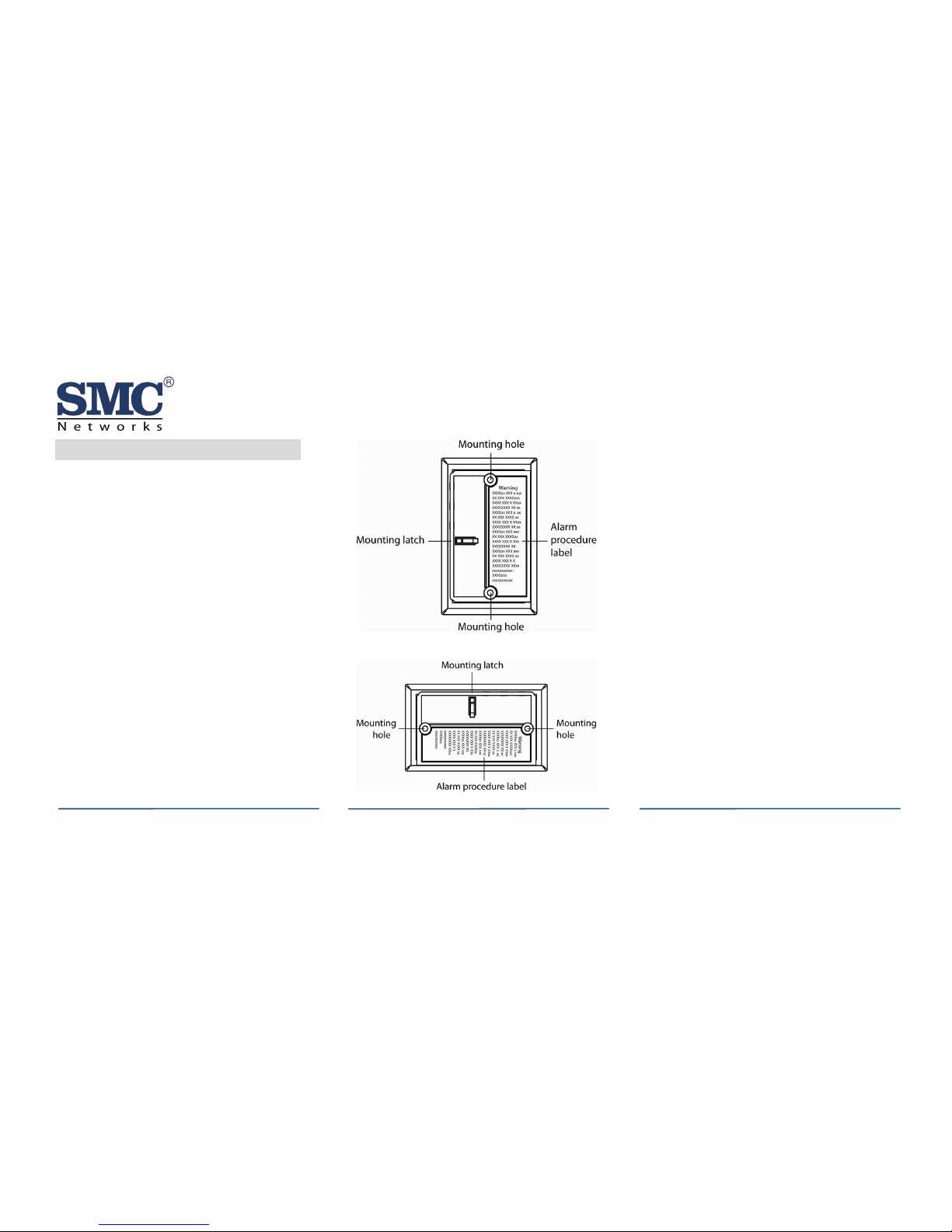
A. Slide the alarm body off the
mounting plate. Place the mounting
plate in the desired location and
mark the location of the 2 mounting
holes. Orient the mounting plate
vertically or horizontally (see Figure
2 and Figure 3).
E. Two labels are provided that have
important information on what to do
in case of an alarm. Record the
phone number of your emergency
service provider in the space
provided. Then place one label next
to the alarm after it is mounted,
and the other label near a fresh-air
source, such as a door or window.
Figure 2. Mounting the Alarm Vertically
Note: The SMCCO02-Z can also be
directly mounted to a single gang box.
Figure 3. Mounting the Alarm Horizontally
Copyright
©
2011 SMC Networks Page 3
All Rights Reserved
I/M SMCWK01-Z rev. 1.0
4/19/11
SMCCO02-Z CO Alarm User Guide
Copyright
©
2011 SMC Networks Page 4
All Rights Reserved
I/M SMCWK01-Z rev. 1.0
4/19/11
3
Installng/RepacingBatteries
The SMCCO02-Z comes with 3 batteries
preinstalled. When you need to replace
them, use the following procedure. Be
sure the SMCCO02-Z is mounted to the
wall and sits on the mounting plate
before performing this procedure.
A. Place the control panel into sensor
test mode. Otherwise, an
alarm/tamper condition may be
indicated.
B. Slide the alarm body off of the
mounting plate.
C. Remove the old batteries and
dispose of them properly, as
recommended by the battery
manufacturer.
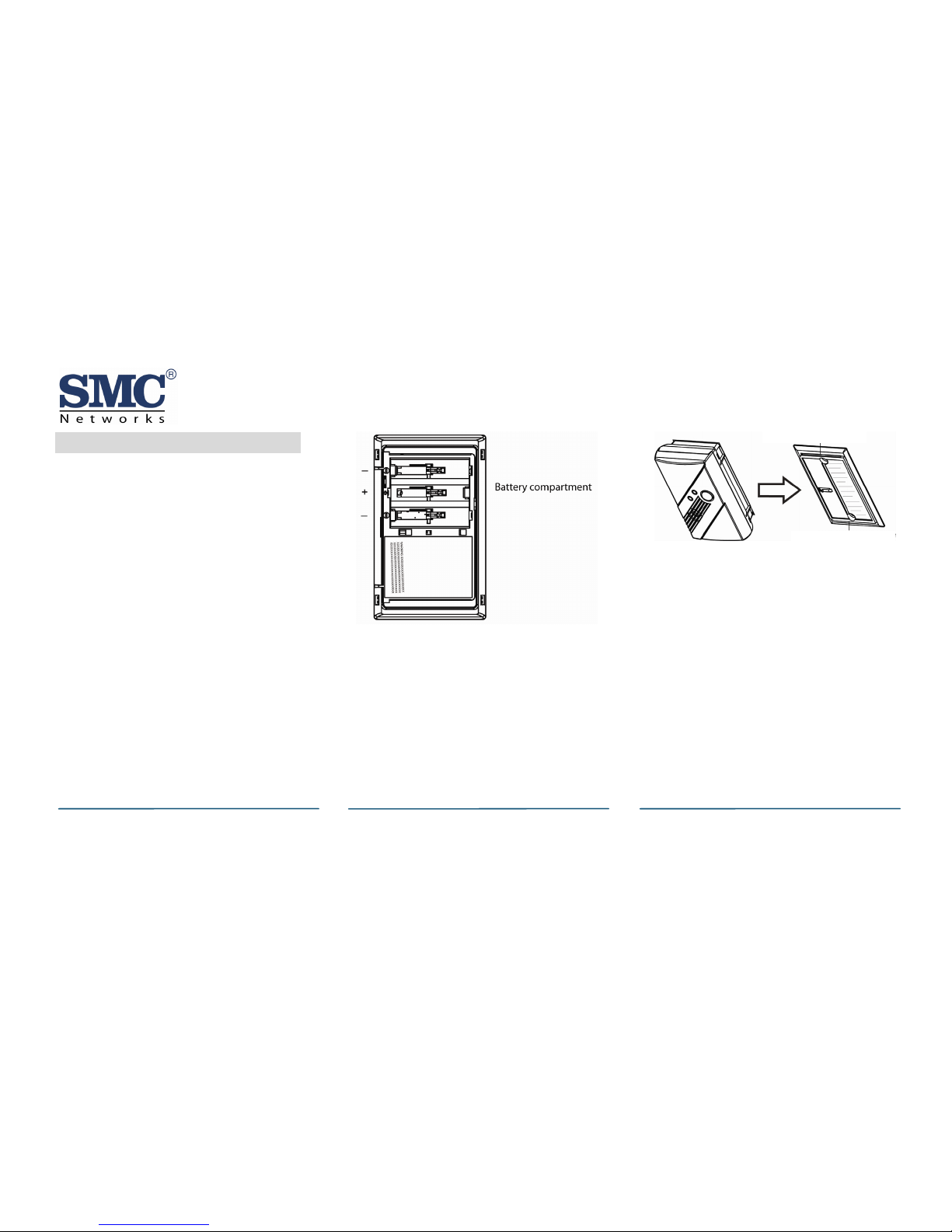
D. Install the new batteries. Note the
polarity shown in the battery
compartment (see Figure 4).
Alarm mounting guide
Alarm mounting guide
Figure 5. Sliding Alarm on Mounting Plate
F. Perform a sensor/RF test with the
control panel. See “Running the RF
Communication Test” on page 7.
G. When replacing batteries, use one
of the following approved brands,
which can be purchased at your
local hardware store:
Figure 4. Installing Batteries
E. Slide the alarm body back onto the
mounting plate.
Note: The mounting plate will not
close if all 3 batteries are not installed.
¾ Duracell MN1500 or MX1500
¾ Energizer E91
Note: Using a different battery can
affect the alarm operation detrimentally.
SMCCO02-Z CO Alarm User Guide
E. At the Locating Wireless Sensors
screen, default the SMCCO02-Z and
place it in Search mode (see se
6 ).
J. Touch the sensor icon to configure
the SMCCO02-Z. The Add
Sensor/Zone Modify screen appears.
When the SMCCO02-Z is configured
properly, touch Next. The Add
Sensor/Zon
Constant exposures to high or low
humidity may reduce battery life.
Copyright
©
2011 SMC Networks Page 5
All Rights Reserved
I/M SMCWK01-Z rev. 1.0
4/19/11
. I.H After installing or changing the
batteries, reinstall your alarm.
Use the Test/Hush
button to test
your alarm. Confirm that the green
Power LED is ON.
4
Ad
ter your
de and touch Done.
uch
a
a
ding to th
ction
Note: The SMCCO02-Z must not be
ed with another TouchScreen. If it is,
ir it (refer to the TouchScreen
llation Manual).
K.
e Modify screen appears.
L. (To modify any text field on the
TouchScreen, such as the Zone
Label, touch the field to display a
keyboard. Then
enter yo
to s
pair
unp
Inst
F. Touch Next. A Stop button appear
on the screen and the TouchScreen
searches for the SMs CCO02-Z to be
added. When the TouchScreen finds
it, a grayed icon appears.
use the keyboard to
ur changes and touch Done
ave your changes.
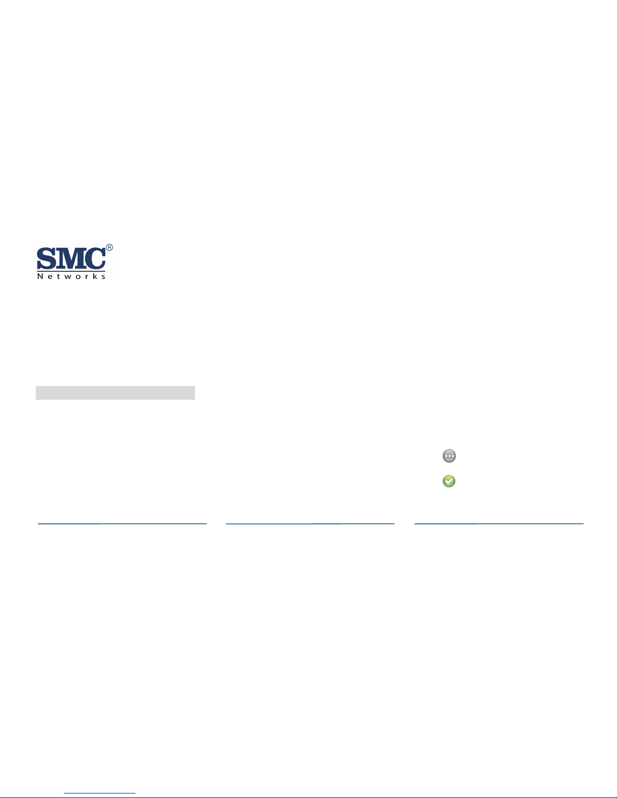
M. As the SMCCO02-Z is configured, the
circle in the top-right of the icon
changes from:
e TouchScreen
A. From the Home screen, touch the
Settings widget.
B. At the keypad, enter the Installer’s
keypad code (not the customer’s
G. Fault the SMCCO02-Z to pair it to
the TouchScreen.
Touch Stop. The Wireless Se
Master keypad code).
C. At the keyboard screen, en
Technician Co
H. nso
I.
to
When the SM
rs
Located screen shows the SMCCO02Z that was found and paired.
Touch Next. The Configure Wireless
D. At the Installer Settings Menu, to
Sensors & Zones > Add a
Sensor/Zone.
Sensors screen shows an icon for the
SMCCO02-Z that was found.
N. CCO02-Z is configured
properly, touch Next in the
Configure Wireless Sensors screen.
 Loading...