

Page 1

Barricade™
Dual WAN Port Load Balancing VPN Router
SMCBR21VPN
Page 2

Copyright
Information furnished by SMC Networks, Inc. (SMC) is believed to be accurate
and reliable. However, no responsibility is assumed by SMC for its use, nor for
any infringements of patents or other rights of third parties which may result from
its use. No license is granted by implication or otherwise under any patent or
patent rights of SMC. SMC reserves the right to change specifications at any
time without notice.
Copyright © 2008 by
SMC Networks, Inc.
20 Mason
Irvine, CA 92618
All rights reserved. Printed in Taiwan
Trademarks:
SMC is a registered trademark; and EZ Connect is a trademark of SMC Networks,
Inc. Other product and company names are trademarks or registered trademarks of
their respective holders.
Page 3

LIMITED W A RRANTY
Limited Warranty S tatement: SMC Networks, Inc. (“SMC”) warrants its products to be free
from defects in workmanship and materials, under normal use and service, for the
applicable warranty term. All SMC products carry a standard 90-day limited warranty from
the date of purchase from SMC or its Authorized Reseller. SMC may , at it s own discretion,
repair or replace any product not operating as warranted with a similar or functionally
equivalent product, during the applicable warranty term. SMC will endeavor to repair or
replace any product returned under warranty within 30 days of receipt of the product. The
standard limited warranty can be upgraded to a Limited Lifetime* warranty by registering
new products within 30 days of purchase from SMC or its Authorized Reseller. Registration
can be accomplished via the enclosed product registration card or online via the SMC
website. Failure to register will not affect the standard limited warranty . The Limited
Lifetime warranty covers a product during the Life of that Product, which is defined as the
period of time during which the product is an “Active” SMC product. A product is
considered to be “Active” while it is listed on the current SMC price list. As new
technologies emerge, older technologies become obsolete and SMC will, at its discretion,
replace an older product in its product line with one that incorporates these newer
technologies. At that point, the obsolete product is discontinued and is no longer an
“Active” SMC product. A list of discontinued products with their respective dates of
discontinuance can be found at:
http://www.smc.com/index.cfm?action=customer_service_warranty .
All products that are replaced become the property of SMC. Replacement products may
be either new or reconditioned. Any replaced or repaired product carries either a 30-day
limited warranty or the remainder of the initial warranty, whichever is longer. SMC is not
responsible for any custom software or firmware, configuration information, or memory
data of Customer contained in, stored on, or integrated with any products returned to SMC
pursuant to any warranty. Products returned to SMC should have any customer-installed
accessory or add-on components, such as expansion modules, removed prior to returning
the product for replacement. SMC is not responsible for these items if they are returned
with the product. Customers must contact SMC for a Return Material Authorization number
prior to returning any product to SMC. Proof of purchase may be required. Any product
returned to SMC without a valid Return Material Authorization (RMA) number clearly
2
Page 4

marked on the outside of the package will be returned to customer at customer’s expense.
For warranty claims within North America, please call our toll-free customer support
number at (800) 762-4968. Customers are responsible for all shipping charges from their
facility to SMC. SMC is responsible for return shipping charges from SMC to customer.
WARRANTIES EX CLUSIV E: IF AN SMC P RODUC T DOES NOT OPERATE AS
WARRANTED ABOVE, CUSTOMER’S SOLE REMEDY SHALL BE REPAIR OR
REPLACEMENT OF THE PRODUCT IN QUESTION, AT SMC’S OPTION. THE
FOREGOING WARRANTIES AND REMEDIES ARE EXCLUSIVE AND ARE IN LIEU OF
ALL OTHER WARRANTIES OR CONDITIONS, EXPRESS OR IMPLIED, EITHER IN
FACT OR BY OPERATION OF LAW, STATUTORY OR OTHERWISE, INCLUDING
WARRANTIES OR CONDITIONS OF M ERCHAN TABILITY AND FITNESS FOR A
PARTICULAR PURPOSE. SMC NEITHER ASSUMES NOR AUTHORIZES ANY OTHER
PERSON TO ASSUME FOR IT ANY OTHER LIABILITY IN CONNECTION WITH THE
SALE, INSTALLATION, MAINTENANCE OR USE OF ITS PRODUCTS. SMC SHALL
NOT BE LIABLE UNDER THIS WARRANTY IF ITS TESTING AND EXAMINATION
DISCLOSE THE ALLEGED DEFECT IN THE PRODUCT DOES NOT EXIST OR WAS
CAUSED BY
CUSTOMER’S OR ANY THIRD PERSON’S MISUSE, NEGLECT, IMPROPER
INSTALLATION OR TESTING, UNAUTHORIZED ATTEMPTS TO REP AIR, OR ANY
OTHER CAUSE BEYOND THE RANGE OF THE INTENDED USE, OR BY ACCIDENT,
FIRE, LIGHTNING, OR OTHER HAZARD.
LIMIT A TION OF LIABILITY : IN NO EVENT, WHETHER BASED IN CONTRACT OR TORT
(INCLUDING NEGLIGENCE), SHALL SMC BE LIABLE FOR INCIDENTAL,
CONSEQUENTIAL, INDIRECT, SPECIAL, OR PUNITIVE DAMAGES OF ANY KIND, OR
FOR LOSS OF REVENUE, LOSS OF BUSINESS, OR OTHER FINANCIAL LOSS
ARISING OUT OF OR IN CONNECTION WITH THE SALE, INSTALLATION,
MAINTENANCE, USE, PERFORMANCE, FAILU R E , O R I N TE R RUP T ION OF ITS
PRODUCTS, EVEN IF SMC OR ITS AUTHOR IZED RES ELLE R HAS BEE N ADVISED
OF THE POSSIBILITY O F SUC H DAMAGES. SOME STATES DO NOT ALLOW THE
EXCLUSION OF IMPLIED WARRANTIES OR THE LIMITATION OF I NC ID ENTAL OR
3
Page 5

CONSEQUENTIAL DAMAGES FOR CO NSUMER PRODUCTS, SO THE ABOVE
LIMIT ATIONS AND EXCLUSIONS MAY NOT APP LY TO YOU. THIS W ARRANTY GIVES
YOU SPECIFIC LEGAL
RIGHTS, WHICH MAY VAR Y FROM STATE TO STA TE. NOTHING IN THIS W A RRANTY
SHALL BE TAKEN TO AFFECT YOUR STATUTORY RIGHTS.
* SMC will provide warranty service for one year following discontinuance from the active
SMC price list. Under the limited lifetime warranty , internal and external power supplies,
fans, and cables are covered by a standard one-year warranty from date of purchase.
SMC Networks, Inc.
20 Mason
Irvine, CA 92618
4
Page 6

COMPLIANCES
FCC - Class A
This equipment has been tested and found to comply with the limits for a Class A digital
device, pursuant to Part 15 of the FCC Rules. These limits are designed to provide
reasonable protection against harmful interference in a residential installation. This
equipment generates, uses and can radiate radio frequency energy and, if not installed
and used in accordance with instructions, may cause harmful interference to radio
communications. However, there is n o guarantee that the interference will not occur in a
particular installation. If this equipment does cause harmful interference to radio or
television reception, which can be determined by turning the equipment off and on, the
user is encouraged to try to correct the interference by one or more of the following
measures:
• Reorient the receiving antenna
• Increase the separation between the equipment and receiver
• Connect the equipment into an outlet on a circuit different from that to which the
receiver is connected
• Consult the dealer or an experienced radio/TV technician for help
EC Conformance Declaration - Class A
SMC contact for these products in Europe is:
SMC Networks Europe,
Edificio Conata II,
Calle Fructuós Gelabert 6-8, 2o, 4a,
08970 - Sant Joan Despí,
Barcelona, Spain.
This information technology equipment complies with the requirements of the Council
Directive 89/336/EEC on the Approximation of the laws of the Member States relating to
Electromagnetic Compatibility and 73/23/EEC for electrical equipment used within
certain
voltage limits and the Amendment Directive 93/68/EEC. For the evaluation of the
compliance with these Directives, the following standards were applied:
5
Page 7

RFI Emission:
• Limit class A according to EN 55022:1998, IEC 60601-1-2 (EMC,medical)
• Limit class A for harmonic current emission according toEN 61000-3-2/1995
• Limitation of voltage fluctuation and flicker in low-voltage supply system
according to EN 61000-3-3/1995
Immunity:
• Product family standard according to EN 55024:1998
• Electrostatic Discharge according to EN 61000-4-2:1995
(Contact Discharge: ±4 kV, Air Discharge: ±8 kV)
• Radio-frequency electromagnetic field according to EN 61000-4-3:1996
(80 - 1000 MHz with 1 kHz AM 80% Modulation: 3 V/m)
• Electrical fast transient/burst according to EN 61000-4-4:1995 (AC/DC
power supply: ±1 kV, Data/Signal lines: ±0.5 kV)
• Surge immunity test according to EN 61000-4-5:1995
(AC/DC Line to Line: ±1 kV, AC/DC Line to Earth: ±2 kV)
• Immunity to conducted disturbances, Induced by radio-frequency fields:
EN 61000-4-6:1996 (0.15 - 80 MHz with
1 kHz AM 80% Modulation: 3 V/m)
• Power frequency magnetic field immunity test according to
EN 61000-4-8:1993 (1 A/m at frequency 50 Hz)
• Voltage dips, short interruptions and voltage variations immunity test
according to EN 61000-4-11:1994 (>95% Reduction @10 ms, 30%
Reduction @500 ms, >95% Reduction @5000 ms)
LVD:
• EN 60950-1:2001
6
Page 8

Please read the following safety information carefully
before installing the device:
WARNING: Installation and removal of the unit must be carried out by
qualified personnel only.
• This guide is intended for use by network administrators who are
responsible for setting up and installing network equipment;
consequently it assumes a basic working knowledge of LANs (Local Area
Networks).
• The unit must be connected to an earthed (grounded) outlet to comply with
international safety standards.
• Do not connect the unit to an A.C. outlet (power supply) without an
earth (ground) connection.
• The appliance coupler (the connector to the unit and not the wall plug)
must have a configuration for mating with an EN 60320/IEC 320
appliance inlet.
• The socket outlet must be near to the unit and easily accessible. You can only
remove power from the unit by disconnecting the power cord from the outlet.
• This unit operates under SELV (Saf ety Extra Low Voltage) conditions
according to IEC 60950. The conditions are only maintained if the
equipment to which it is connected also operates under SELV
conditions.
7
Page 9

Veuillez lire à fond l’information de la sécurité suivante avant d’installer le Device:
AVERTISSEMENT: L.installation et la dépose de ce groupe doivent être
confiés à un personnel qualifié.
• Ne branchez pas votre appareil sur une prise secteur (alimentation
électrique) lorsqu’il n’y a pas de connexion de mise à la terre (mise à la
masse).
• Vous devez raccorder ce groupe à une sortie mise à la terre (mise à la masse)
afin de respecter les normes internationales de sécurité.
• Le coupleur d.appareil (le connecteur du groupe et non pas la prise
murale) doit respecter une configuration qui permet un branchement sur une
entrée d.appareil EN 60320/IEC 320.
• La prise secteur doit se trouver à proximité de l.appareil et son accès doit être
facile. Vous ne pouvez mettre l.appareil hors circuit qu.en
débranchant son cordon électrique au niveau de cette prise.
• L.appareil fonctionne à une tension extrêmement basse de sécurité qui
est conforme à la norme IEC 60950. Ces conditions ne sont maintenues que si
l.équipement auquel il est raccordé fonctionne dans les mêmes conditions.
Bitte unbedingt vor dem Einbauen des RPU die
folgenden Sicherheitsanweisungen durchlesen:
WARNUNG: Die Installation und der Ausbau des Geräts darf nur durch
Fachpersonal erfolgen.
• Diese Anleitung ist fr die Benutzung durch Netzwerkadministratoren
vorgesehen, die fr die Installation und das einstellen von
Netzwerkkomponenten verantwortlich sind; sie setzt Erfahrung bei der Arbeit mit
LANs (Local Area Networks) voraus.
• Das Gerät sollte nicht an eine ungeerdete Wechselstromsteckdose
angeschlossen werden.
8
Page 10

• Das Gerät muß an eine geerdete Steckdose angeschlossen werden,
welche die internationalen Sicherheitsnormen erfüllt.
• Der Gerätestecker (der Anschluß an das Gerät, nicht der
Wandsteckdosenstecker) muß einen gemäß EN 60320/IEC 320
konfigurierten Geräteeingang haben.
• Die Netzsteckdose muß in der Nähe des Geräts und leicht zugänglich
sein. Die Stromversorgung des Geräts kann nur durch Herausziehen des
Gerätenetzkabels aus der Netzsteckdose unterbrochen werden.
• Der Betrieb dieses Geräts erfolgt unter den SELV-Bedingungen
(Sicherheitskleinstspannung) gemäß IEC 60950. Diese Bedingungen sind
nur gegeben, wenn auch die an das Gerät angeschlossenen Geräte unter
SELV-Bedingungen betrieben werden
Stromkabel. Dies muss von dem Land, in dem es
benutzt wird geprüft werden:
Dieser Stromstecker muß die SEV/ASE
Schweiz
1011Bestimmungen ein- halten.
Das Netzkabel muß vom Typ
Europe
HO3VVF3GO.75 (Mindestan-
forderung) sein und die Aufschrift <HAR>
oder <BASEC> tragen
Der Netzstecker muß die Norm CEE 7/7
erfüllen (.SCHUKO.).
9
Page 11

Warnings and Cautionary Messages
Warning: This product does not contain any serviceable user parts.
Warning: Installation and removal of the unit must be carried out by qualified personnel
only.
Warning: When connecting this device to a power outlet, connect the field ground lead
on the tri-pole power plug to a valid earth ground line to prevent electrical
hazards.
Caution: Wear an anti-static wrist strap or take other suitable measures to prevent
electrostatic discharge when handling this equipment.
Caution: Do not plug a phone jack connector in the RJ-45 port. This may damage this
device. Les raccordeurs ne sont pas utilisé pour le système téléphonique!
Caution: Use only twisted-pair cables with RJ-45 connectors that conform to FCC
standards.
Warnings (in German)
Achtung: Dieses Produkt enthält keine Teile, die eine Wartung vom Benutzer
benötigen.
Achtung: Installation und Deinstallation des Gerätes müssen von qualifiziertem
Servicepersonal durchgeführt werden.
Achtung: Wenn das Gerät an eine Steckdose angeschlossen wird, muß der
Masseanschluß
n Netzstecker mit Schutzerde verbunden werden, um elektrische
Gefahren zu vermeiden.
10
Page 12

Environmental Statement
The manufacturer of this product endeavours to sustain an environmentally-friendly
policy throughout the entire production process. This is achieved though the following
means:
• Adherence to national legislation and regulations on environmental production
standards.
• Conservation of operational resources.
• Waste reduction and safe disposal of all harmful un-recyclable by-products.
• Recycling of all reusable waste content.
• Design of products to maximize recyclables at the end of the product.s life span.
• Continual monitoring of safety standards.
End of Product Life Span
This product is manufactured in such a way as to allow for the recovery and disposal of
all included electrical components once the product has reached the end of its life.
Manufacturing Materials
There are no hazardous nor ozone-depleting materials in this product.
Documentation
All printed documentation for this product uses biodegradable paper that originates from
sustained and managed forests. The inks used in the printing process are non-toxic.
Purpose
This guide details the hardware features of the product, including Its physical and
performance-related characteristics, and how to install the product.
11
Page 13

Audience
The guide is intended for use by network administrators who are responsible for
installing and setting up network equipment; consequently, it assumes a basic working
knowledge of LANs (Local Area Networks).
Diese Anleitung ist für die Benutzung durch Netzwerkadministratoren vorgesehen, die
für die Installation und das einstellen von Netzwerkkomponenten verantwortlich sind;
sie setzt Erfahrung bei der Arbeit mit LANs (Local Area Networks) voraus.
12
Page 14

Contents
CHAPTER 1 ADMINISTRATOR...........................................................................................................16
ADMIN....................................................................................................................................................18
LOGOUT..................................................................................................................................................21
SOFTWARE UPDATE.................................................................................................................................22
CHAPTER 2 CONFIGURE....................................................................................................................23
SETTING..................................................................................................................................................28
DATE / TIME............................................................................................................................................34
MULTIPLE SUBNET..................................................................................................................................35
ROUTE TABLE.........................................................................................................................................38
DDNS ....................................................................................................................................................44
HOST TABLE ...........................................................................................................................................46
LANGUAGE .............................................................................................................................................47
CHAPTER 3 INTERFACE......................................................................................................................48
LAN.......................................................................................................................................................53
WAN ......................................................................................................................................................54
DMZ ...................................................................................................................................................... 62
CHAPTER 4 ADDRESS ..........................................................................................................................64
EXAMPLE................................................................................................................................................67
CHAPTER 5 SERVICE...........................................................................................................................74
CUSTOM..................................................................................................................................................78
GROUP....................................................................................................................................................82
CHAPTER 6 SCHEDULE.......................................................................................................................85
EXAMPLE................................................................................................................................................86
CHAPTER 7 QOS....................................................................................................................................88
EXAMPLE................................................................................................................................................92
13
Page 15

CHAPTER 8 AUTHENTICATION ........................................................................................................94
EXAMPLE..............................................................................................................................................100
CHAPTER 9 CONTENT BLOCKING................................................................................................104
URL .....................................................................................................................................................108
SCRIPT................................................................................................................................................111
DOWNLOAD..........................................................................................................................................113
P2P / IM ...............................................................................................................................................115
CHAPTER 10 VIRTUAL SERVER......................................................................................................118
EXAMPLE..............................................................................................................................................122
CHAPTER 11 VPN.................................................................................................................................137
EXAMPLE..............................................................................................................................................145
CHAPTER 12 POLICY.........................................................................................................................169
EXAMPLE..............................................................................................................................................175
CHAPTER 13 ALERT SETTING......................................................................................................193
INTERNET ALERT ..................................................................................................................................198
CHAPTER 14 ATTACK ALARM......................................................................................................202
INTERNAL ALARM.................................................................................................................................204
EXTERNAL ALARM ...............................................................................................................................205
CHAPTER 15 LOG.............................................................................................................................207
TRAFFIC LOG........................................................................................................................................209
EVENT LOG...........................................................................................................................................214
CONNECTION LOG ................................................................................................................................217
LOG BACKUP........................................................................................................................................220
CHAPTER 16 ACCOUNTING REPORT.........................................................................................222
OUTBOUND...........................................................................................................................................225
INBOUND ..............................................................................................................................................232
14
Page 16

CHAPTER 17 STATISTICS...............................................................................................................238
WAN STATISTICS ..................................................................................................................................240
POLICY STATISTICS ...............................................................................................................................242
CHAPTER 18 STATUS....................................................................................................................... 244
INTERFACE............................................................................................................................................245
AUTHENTICATION.................................................................................................................................247
ARP TABLE...........................................................................................................................................248
DHCP CLIENTS ....................................................................................................................................249
15
Page 17

Chapter 1 Administrator
Administration
“System” is the managing of settings such as the privileges of packets that pass
through the SMC BR21VPN and monitoring controls. The System Administrators
can manage, monitor, and configure SMC BR21VPN settings. But all
configurations are “read-only” for all users other than the System Administrator;
those users are not able to change any setting of the SMC BR21VPN.
16
Page 18

Define the required fields of Administrator
Administrator Name:
The username of Administrators and Sub Administrator for the SMC
BR21VPN. The admin user name cannot be removed; and the sub-admin
user can be removed or configure.
The default Account: admin; Password: smcadmin
Privilege:
The privileges of Administrators (Admin or Sub Admin). The username of
the main Administrator is Administrator with reading / writing privilege.
Administrator also can change the system setting, log system status, and to
increase or delete sub-administrator. Sub-Admin may be created by the
Admin by clicking
New Sub Admin
. Sub Admin have only read and
monitor privilege and cannot change any system setting value.
Configure:
Click Modify to change the “Sub-Administrator’s” password or click
Remove to delete a “Sub Administrator.”
17
Page 19

Admin
Adding a new Sub Administrator
STEP 1﹒In the Admin WebUI, click the New Sub Admin button to create a
new Sub Administrator.
STEP 2﹒In the Add New Sub Administrator WebUI (Figure 1-1) and enter the
following setting:
Sub Admin Name: sub_admin
Password: 12345
Confirm Password: 12345
STEP 3﹒Click OK to add the user or click Cancel to cancel it.
Figure1-1 Add New Sub Admin
18
Page 20

Modify the Administrator’s Password
STEP 1﹒In the Admin WebUI, locate the Administrator name you want to edit,
and click on Modify in the Configure field.
STEP 2﹒The Modify Administrator Password WebUI will appear. Enter the
following information:
Password: admin
New Password: 52364
Confirm Password: 52364 (Figure1-2)
STEP 3﹒Click OK to confirm password change.
Figure1-2 Modify Admin Password
19
Page 21
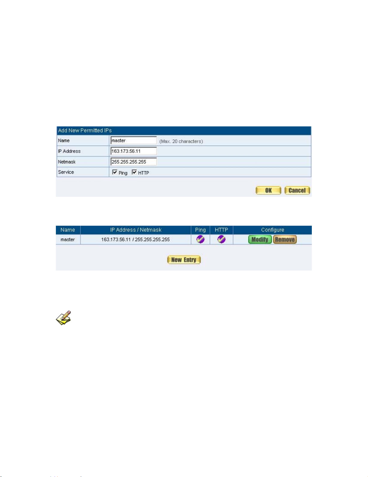
Add Remote Management IPs
STEP 1﹒Add the following setting in Permitted IPs of Administration:
(Figure1-3)
Name: Enter master
IP Address: Enter 163.173.56.11
Netmask: Enter 255.255.255.255
Service: Select Ping and HTTP
Click OK
Complete add new permitted IPs (Figure1-4)
Figure1-3 Setting Permitted IPs WebUI
Figure1-4 Complete Add New Permitted IPs
To make Permitted IPs be effective, it must cancel the Ping and WebUI selection
in the WebUI of SMC BR21VPN that Administrator enter. (LAN, WAN, or DMZ Interface)
Before canceling the WebUI selection of Interface, must set up the Permitted IPs first,
otherwise, it would cause the situation of cannot enter WebUI by appointed Interface.
20
Page 22

Logout
STEP 1﹒Click Logout in System to protect the system while Administrator are
away. (Figure1-5)
Figure1-5 Confirm Logout WebUI
STEP 2﹒Click OK and the logout message will appear in WebUI. (Figure1-6)
Figure1-6 Logout WebUI Message
21
Page 23

Software Update
STEP 1﹒Select Software Update in System, and follow the steps below:
To obtain the version number from Version Number and obt ain the
latest version from Internet. And save the latest version in the
hardware of the PC, which manage the SMC BR21VPN
Click Browse and choose the latest software version file.
Click OK and the system will update automatically. (Figure1-7)
Figure1-7 Software Update
It takes 3 minutes to update software. The system will reboot after update. During
the updating time, please don’t turn off the PC or leave the WebUI. It may cause some
unexpected mistakes. (Strong suggests updating the software from LAN to avoid
unexpected mistakes.)
22
Page 24

Chapter 2 Configure
Configure
The Configure is according to the basic setting of the SMC BR21VPN. In this
chapter the definition is Setting, Date/Time, Multiple Subnet, Route Table, DHCP,
Dynamic DNS, Hosts Table, and Language settings.
23
Page 25

Define the required fields of Settings
SMC BR21VPN Configuration:
The Administrator can import or export the system settings. Click OK to
import the file into the SMC BR21VPN or click Cancel to cancel importing.
You also can revive to default value here.
Email Settings:
Select Enable E-mail Alert Notification under E-mail Settings. This
function will enable the SMC BR21VPN to send e-mail alerts to the System
Administrator when the network is being attacked by hackers or when
emergency conditions occur. (It can be set from Settings-Hacker Alert in
System to detect Hacker Attacks)
Web Management (WAN Interface):
The System Manager can change the port number used by HTTP port
anytime. (Remote WebUI management)
After HTTP port has changed, if the administrator want to enter WebUI from WAN,
will have to change the port number of browser. (For example:
http://61.62.108.172:8080)
MTU Setting:
It provides the Administrator to modify the networking package length
anytime. Its default value is 1500 Bytes.
Link Speed / Duplex Mode:
By this function can set the transmission speed and mode of WAN Port
when connecting other device.
24
Page 26

Administration Packet Logging:
After enable this function; the SMC BR21VPN will record packet which
source IP or destination address is SMC BR21VPN. And record in Traffic
Log for System Manager to inquire about.
Define the required fields of Time Settings
Synchronize Time/Date:
Synchronizing the SMC BR21VPN with the System Clock. The
administrator can configure the SMC BR21VPN’s date and time by either
syncing to an Internet Network Time Server (NTP) or by syncing to your
computer’s clock.
GMT:
International Standard Time (Greenwich Mean Time)
Define the required fields of Multiple Subnet
Forwarding Mode:
To display the mode that Multiple Subnet use. (NAT mode or Routing Mode)
WAN Interface Address:
The IP address that Multiple Subnet corresponds to WAN.
LAN Interface Address/Subnet Netmask:
The Multiple Subnet range
25
Page 27

NAT Mode:
It allows Internal Network to set multiple subnet address and connect with
the Internet through different WAN IP Addresses. For example:The lease
line of a company applies several real IP Addresses 168.85.88.0/24, and the
company is divided into R&D department, service, sales department,
procurement department, accounting department, the company can
distinguish each department by different subnet for the purpose of
managing conveniently. The settings are as the following:
1. R&D department subnet:192.168.1.1/24(LAN) ÅÆ 168.85.88.253(W AN)
2. Service department subnet: 192.168.2.1/24(LAN) ÅÆ
168.85.88.252(WAN)
3. Sales department subnet: 192.168.3.1/24(LAN) ÅÆ
168.85.88.251(WAN)
4. Procurement department subnet
192.168.4.1/24(LAN) ÅÆ 168.85.88.250(WAN)
5. Accounting department subnet
192.168.5.1/24(LAN) ÅÆ 168.85.88.249(WAN)
The first department (R&D department) had set while setting interface IP; the
other four ones have to be added in Multiple Subnet. After completing the
settings, each department uses the different WAN IP Address to connect to the
Internet. The settings of each department are as following:
Service Sales Procurement Accounting
IP
192.168.2.2~254 192.168.3.2~254 192.168.4.2~254 192.168.5.2~254
Address
Subnet
255.255.255.0 255.255.255.0 255.255.255.0 255.255.255.0
Netmask
Gateway 192.168.2.1 192.168.3.1 192.168.4.1 192.168.5.1
Routing Mode:
It is the same as NAT mode approximately but does not have to correspond
to the real WAN IP address, which let intern al PC to ac cess to Inte rnet by its
own IP. (External user also can use the IP to connect with the Internet)
26
Page 28

Define the required fields of DHCP
Subnet:
The domain name of LAN
NetMask:
The LAN Netmask
Gateway:
The default Gateway IP address of LAN
Broadcast IP:
The Broadcast IP of LAN
Define the required fields of DDNS
Domain Name:
The domain name that provided by DDNS
WAN IP Address:
The WAN IP Address, which the domain name corresponds to.
Define the required fields of Host Table
Domain Name:
It can be set by System Manager. To let the internal user to access to the
information that provided by the host by this domain name
Virtual IP Address:
The virtual IP address respective to Host Table. It must be LAN or DMZ IP
address.
27
Page 29

Setting
System Settings- Exporting
STEP 1﹒In System Setting WebUI, click on button next to
Export System Settings to Client.
STEP 2﹒When the File Download pop-up window appears, choose the
destination place where to save the exported file and click on Save.
The setting value of SMC BR21VPN will copy to the appointed site
instantly. (Figure2-1)
Figure2-1 Select the Destination Place to Save the Exported File
28
Page 30

System Settings- Importing
STEP 1﹒In System Setting WebUI, click on the Browse button next to Import
System Settings from Client. When the Choose File pop-up window
appears, select the file to which contains the saved SMC BR21VPN
Settings, then click OK. (Figure2-2)
STEP 2﹒Click OK to import the file into the SMC BR21VPN (Figure2-3)
Figure 2-2 Enter the File Name and Destination of the Imported File
Figure 2-3 Upload the Setting File WebUI
29
Page 31

Restoring Factory Default Settings
STEP 1﹒Select Reset Factory Settings in SMC BR21VPN Configuration
WebUI
STEP 2﹒Click OK at the bottom-right of the page to restore the factory settings.
(Figure2-4)
30
Page 32

Figure2-4 Reset Factory Settings
31
Page 33

Enabling E-mail Alert Notification
STEP 1﹒Select Enable E-mail Alert Notification under E-Mail Settings.
STEP 2﹒Device Name: Enter the Device Name or use the default value.
STEP 3﹒Sender Address: Enter the Sender Address. (Required by some
ISPs.)
STEP 4﹒SMTP Server IP: Enter SMTP server’s IP address.
STEP 5﹒E-Mail Address 1: Enter the e-mail address of the first user to be
notified.
STEP 6﹒E-Mail Address 2: Enter the e-mail address of the second user to be
notified. (Optional)
STEP 7﹒Click OK on the bottom-right of the screen to enable E-mail Alert
Notification. (Figure2-5)
Figure2-5 Enable E-mail Alert Notification
Click on Mail Test to test if E-mail Address 1 and E-mail Address 2 can receive the
Alert Notification correctly.
32
Page 34

Reboot SMC BR21VPN
STEP 1﹒Reboot SMC BR21VPN:Click Reboot button next to Reboot SMC
BR21VPN Appliance.
STEP 2﹒A confirmation pop-up page will appear.
STEP 3﹒Follow the confirmation pop-up page; click OK to restart SMC
BR21VPN. (Figure2-6)
Figure2-6 Reboot SMC BR21VPN
33
Page 35

Date / Time
Date/Time Settings
STEP 1﹒Select Enable synchronize with an Internet time Server (Figure2-7)
STEP 2﹒Click the down arrow to select the offset time from GMT.
STEP 3﹒Enter the Server IP / Name with which you want to synchronize.
STEP 4﹒Set the interval time to synchronize with outside servers.
Figure2-7 System Time Setting
Click on the Sync button and then the SMC BR21VPN’s date and time will be
synchronized to the Administrator’s PC
The value of Set Offset From GMT and Server IP / Name can be looking for from
Assist.
34
Page 36

Multiple Subnet
Connect to the Internet through Multiple Subnet NAT or Routing Mode by the IP
address that set by the LAN user’s network card
Preparation
SMC BR21VPN WAN1 (10.10.10.1) connect to the ISP Router (10.10.10.2) and
the subnet that provided by ISP is 162.172.50.0/24
To connect to Internet, WAN2 IP (211.22.22.22) connects with ATUR.
35
Page 37

Adding Multiple Subnet
Add the following settings in Multiple Subnet of System function:
Click on New Entry
Alias IP of LAN Interface: Enter 162.172.50.1
Netmask:Enter 255.255.255.0
WAN1: Enter Interface IP 10.10.10.1, and choose Routing in
Forwarding Mode
WAN2:Enter Interface IP 211.22.22.22, and choose NAT in
Forwarding Mode
Click OK
Complete Adding Multiple Subnet (Figure2-8)
Figure 2-8 Add Multiple Subnet WebUI
36
Page 38

WAN1 and WAN2 Interface can use Assist to enter the data.
After setting, there will be two subnet in LAN: 192.168.1.0/24 (default LAN subnet)
and 162.172.50.0/24. So if LAN IP is:
˙192.168.1.xx, it must use NAT Mode to access to the Internet. (In Policy it only can
setup to access to Internet by WAN2. If by WAN1 Routing mode, then it cannot access
to Internet by its virtual IP)
˙162.172.50.xx, it uses Routing mode through WAN1 (The Internet Server can see your
IP 162.172.50.xx directly). And uses NAT mode through WAN2 (The Internet Server
can see your IP as WAN2 IP)(Figure2-9)
Figure 2-9 Multiple Subnet Network
The SMC BR21VPN’s Interface Status:
WAN1 IP: 10.10.10.1
WAN2 IP:211.22.22.22
LAN Port IP:192.168.1.1
LAN Port Multiple Subnet:162.172.50.1
37
Page 39

Route Table
To connect two different subnet router with the SMC BR21VPN and
makes them to connect to Internet through SMC BR21VPN
Preparation
Company A: WAN1 (61.11.11.11) connects with ATUR to Internet
WAN2 (211.22.22.22) connects with ATUR to Internet
LAN subnet: 192.168.1.1/24
The Router1 which connect with LAN (10.10.10.1, support RIPv2)
its LAN subnet is 192.168.10.1/24
Company B: Router2 (10.10.10.2, support RIPv2), its LAN subnet is
192.168.20.1/24
Company A ‘s Router1 (10.10.10.1) connect directly with Company B ‘s Router2
(10.10.10.2).
38
Page 40

Route Table
STEP 1﹒Enter the following settings in Route Table in System function:
【Destination IP】: Enter 192.168.10.1
【Netmask】: Enter 255.255.255.0。
【Gateway】: Enter 192.168.1.252
【Interface】: Select LAN
Click OK (Figure 2-10)
Figure2-10 Add New Static Route1
STEP 2﹒Enter the following settings in Route Table in System function:
【Destination IP】: Enter 192.168.20.1
【Netmask】: Enter 255.255.255.0
【Gateway】: Enter 192.168.1.252
【Interface】: Select LAN
Click OK (Figure 2-11)
Figure2-11 Add New Static Route2
39
Page 41

STEP 3﹒Enter the following setting in Route Table in System function:
【Destination IP】: Enter 10.10.10.0
【Netmask】: Enter 255.255.255.0
【Gateway】: Enter 192.168.1.252
【Interface】: Select LAN
Click OK (Figure 2-12)
Figure2-12 Add New Static Route3
40
Page 42

STEP 4﹒Adding successful. At this time the computer of 192.168.10.1/24,
192.168.20.1/24 and 192.168.1.1/24 can connect with each other and
connect to Internet by NAT (Figure 2-13)
Figure 2-13 Route Table Setting
41
Page 43

DHCP
STEP 1﹒Select DHCP in System and enter the following settings:
Domain Name:Enter the Domain Name
DNS Server 1: Enter the distributed IP address of DNS Server1.
DNS Server 2: Enter the distributed IP address of DNS Server2.
WINS Server 1: Enter the distributed IP address of WINS Server1.
WINS Server 2: Enter the distributed IP address of WINS Server2.
LAN Interface:
Client IP Address Range 1: Enter the starting and the ending
IP address dynamically assigning to DHCP clients. The default
value is 192.168.1.2 to 192.168.1.254 (it must be in the same
subnet)
Client IP Address Range 2: Enter the starting and the ending
IP address dynamically assigning to DHCP clients. But it must
in the same subnet as Client IP Address Range 1 and the
range cannot be repeated.
DMZ Interface: the same as LAN Interface. (DMZ works only if to
enable DMZ Interface)
Leased Time: Enter the leased time for Dynamic IP. The default time is
24 hours.
Click OK and DHCP setting is completed. (Figure2-14)
42
Page 44

Figure 2-14 DHCP WebUI
When selecting Automatically Get DNS, the DNS Server will lock it as LAN
Interface IP. (Using Occasion: When the system Administrator starts Authentication, the
users’ first DNS Server must be the same as LAN Interface IP in order to enter
Authentication WebUI)
43
Page 45

DDNS
Dynamic DNS Settings
STEP 1﹒Select Dynamic DNS in System function (Figure2-15). Click New
Entry button
Service providers:Select service providers.
Automatically fill in the W AN 1/2 IP :Check to automatically fill
in the WAN 1/2 IP.。
User Name:Enter the registered user name.
Password:Enter the password
Domain name:Enter Your host domain name
Click OK to add Dynamic DNS. (Figure2-16)
Figure2-15 DDNS WebUI
Figure 2-16 Complete DDNS Setting
44
Page 46

Chart
Meaning Update
successfully
Incorrect
username or
Connecting
to server
Unknown error
password
If System Administrator had not registered a DDNS account, click on Sign up then
can enter the website of the provider.
If you do not select Automatically fill in the WAN IP and then you can enter a
specific IP in WAN IP. Let DDNS to correspond to that specific IP address.
45
Page 47

Host Table
STEP 1﹒Select Host Table in Settings function and click on New Entry
Domain Name: The domain name of the server
Virtual IP Address: The virtual IP address respective to Host
Table
Click OK to add Host Table. (Figure2-17)
Figure2-17 Add New Host Table
To use Host Table, the user PC’s first DNS Server must be the same as the LAN
Port or DMZ Port IP of SMC BR21VPN. That is, the default gateway.
46
Page 48

Language
Select the Language version (English Version/ T raditional Chinese Version or
Simplified Chinese Version) and click OK. (Figure2-18)
Figure2-18 Language Setting WebUI
47
Page 49

Chapter 3 Interface
Interface
In this section, the Administrator can set up the IP addresses for the office
network. The Administrator may configure the IP addresses of the LAN
network, the WAN 1/2 network, and the DMZ network. The Netmask and
gateway IP addresses are also configured in this section.
48
Page 50

Define the required fields of Interface
LAN:
Using the LAN Interface, the Administrator can set up the LAN network of
SMC BR21VPN.
Ping:
Select this function to allow the LAN users to ping the Interface IP Address.
HTTP:
Select to enable the user to enter the WebUI of SMC BR21VPN from
Interface IP.
WAN:
The System Administrator can set up the WAN network of SMC BR21VPN.
Balance Mode:
Auto: The SMC BR21VPN will adjust the WAN 1/2 utility rate automatically
according to the downstream/upstream of WAN. (For users who are using
various download bandwidth)
Round-Robin: The SMC BR21VPN distributes the WAN 1/2 download
bandwidth 1:1, in other words, it selects the agent by order. (For users who
are using same download bandwidths)
By Traffic: The SMC BR21VPN distributes the WAN 1/2 download
bandwidth by accumulative traffic.
By Session: The SMC BR21VPN distributes the WAN 1/2 download
bandwidth by saturated connections.
By Packet: The SMC BR21VPN distributes the WAN 1/2 download
bandwidth by accumulated packets and saturated connection.
49
Page 51

Connect Mode:
Display the current connection mode:
PPPoE (ADSL user)
Dynamic IP Address (Cable Modem User)
Static IP Address
Saturated Connections:
Set the number for saturation whenever session numbers reach it, the SMC
BR21VPN switches to the next agent on the list.
Priority:
Set priority of WAN for Internet Access.
Connection Test:
To test if the WAN network can connect to Internet or not. The testing ways
are as following:
ICMP:To test if the connection is successful or not by the Ping IP you
set.
DNS:To test if the connection is successful or not by checking Domain
Name.
Upstream/Downstream Bandwidth:
The System Administrator can set up the correct Bandwidth of WAN
network Interface here.
Auto Disconnect:
The PPPoE connection will automatically disconnect after a length of idle
time (no activities). Enter the amount of idle time before disconnection in the
field. Enter “0” if you do not want the PPPoE connection to disconnect at all.
50
Page 52

DMZ:
The Administrator uses the DMZ Interface to set up the DMZ network.
The DMZ includes:
NAT Mode:In this mode, the DMZ is an independent virtual subnet.
This virtual subnet can be set by the Administrator but cannot be the
same as LAN Interface.
Transparent Mode: In this mode, the DMZ and WAN Interface are in
the same subnet.
51
Page 53

We set up four Interface Address examples in this chapter:
No. Suitable
Situation
Ex1
Ex2
Ex3
Ex4
LAN
WAN
DMZ
DMZ
Example Page
Modify LAN Interface Settings
Setting WAN Interface Address
Setting DMZ Interface Address (NAT Mode)
Setting DMZ Interface Address (Transparent
41
42
50
51
Mode)
52
Page 54

LAN
Modify LAN Interface Settings
STEP 1﹒Select LAN in Interface and enter the following setting:
Enter the new IP Address and Netmask
Select Ping and HTTP
Click OK (Figure3-1)
Figure3-1 Setting LAN Interface WebUI
The default LAN IP Address is 192.168.1.1. After the Administrator setting the
new LAN IP Address on the computer , he/she have to restart the System to make the
new IP address effective. (when the computer obtain IP by DHCP)
Do not cancel WebUI selection before not setting Permitted IPs yet. It will cause
the Administrator cannot be allowed to enter the SMC BR21VPN’s WebUI from LAN.
53
Page 55

WAN
Setting WAN Interface Address
STEP 1﹒Select WAN in Interface and click Modify in WAN1 Interface.
The setting of WAN2 Interface is almost the same as WAN1. The difference is that
WAN2 has a selection of Disable. The System Administrator can close WAN2 Interface
by this selection. (Figure3-2)
Figure3-2 Disable WAN2 Interface
54
Page 56

STEP 2﹒Setting the Connection Service (ICMP or DNS way):
ICMP:Enter an Alive Indicator Site IP (can select from Assist)
(Figure3-3)
DNS:Enter DNS Server IP Address and Domain Name (can
select from Assist) (Figure3-4)
Setting time of seconds between sending alive packet.
Figure3-3 ICMP Connection
Figure 3-4 DNS Service
Connection test is used for SMC BR21VPN to detect if the WAN can connect or
not. So the
be able to use permanently. Or it will cause judgmental mistakes of the device.
Alive Indicator Site IP, DNS Server IP Address, or Domain Name must
55
Page 57

STEP 3﹒Select the Connecting way:
PPPoE (ADSL User) (Figure3-5):
1. Select PPPoE
2. Enter User Name as an account
3. Enter Password as the password
4. Select Dynamic or Fixed in IP Address provided by ISP . If you
select Fixed, please enter IP Address, Netmask, and Default
Gateway.
5. Enter Max. Downstream Bandwidth and Max. Upstream
Bandwidth. (According to the flow that user apply)
6. Select Ping and HTTP
7. Click OK (Figure3-6)
56
Page 58

Figure3-5 PPPoE Connection
Figure3-6 Complete PPPoE Connection Setting
If the connection is PPPoE, you can choose Service-On-Demand for WAN
Interface to connect automatically when disconnect; or to set up Auto Disconnect if
idle (not recommend)
57
Page 59

Dynamic IP Address (Cable Modem User) (Figure3-7):
1. Select Dynamic IP Address (Cable Modem User)
2. Click Renew in the right side of IP Address and then can obtain
IP automatically.
3. If the MAC Address is required for ISP then click on Clone MAC
Address to obtain MAC IP automatically.
4. Hostname: Enter the hostname provided by ISP.
5. Domain Name: Enter the domain name provided by ISP.
6. User Name and Password are the IP distribution method
according to Authentication way of DHCP+ protocol (like ISP in
China)
7. Enter Max. Downstream Bandwidth and Max. Upstream
Bandwidth (According to the flow that user apply)
8. Select Ping and HTTP
9. Click OK (Figure3-8)
58
Page 60

Figure3-7 Dynamic IP Address Connection
Figure3-8 Complete Dynamic IP Connection Setting
59
Page 61

Static IP Address (Figure3-9)
1. Select Static IP Address
2. Enter IP Address, Netmask, and Default Gateway that
provided by ISP
3. Enter DNS Server1 and DNS Server2
In WAN2, the connecting of Static IP Address does not need to set DNS Server
4. Enter Max. Downstream Bandwidth and Max. Upstream
Bandwidth (According to the flow that user apply)
5. Select Ping and HTTP
6. Click OK (Figure3-10)
Figure3-9 Static IP Address Connection
60
Page 62

Figure3-10 Complete Static IP Address Connection Setting
When selecting Ping and WebUI on WAN network Interface, users will be able to
ping the SMC BR21VPN and enter the WebUI WAN network. It may influence network
security. The suggestion is to Cancel Ping and WebUI after all the settings have
finished. And if the System Administrator needs to enter UI from WAN, he/she can use
Permitted IPs to enter.
61
Page 63

DMZ
Setting DMZ Interface Address (NAT Mode)
STEP 1﹒Click DMZ Interface
STEP 2﹒Select NAT Mode in DMZ Interface
Select NAT in DMZ Interface
Enter IP Address and Netmask
STEP 3﹒Select Ping and HTTP
STEP 4﹒Click OK (Figure3-11)
Figure3-11 Setting DMZ Interface Address (NAT Mode) WebUI
62
Page 64

Setting DMZ Interface Address (Transparent Mode)
STEP 1﹒Select DMZ Interface
STEP 2﹒Select Transparent Mode in DMZ Interface
Select DMZ_Transparent in DMZ Interface
STEP 1﹒Select Ping and HTTP
STEP 2﹒Click OK (Figure3-12)
Figure 3-12 Setting DMZ Interface Address (Transparent Mode) WebUI
In WAN, the connecting way must be Static IP Address and can choose
Transparent Mode in DMZ.
63
Page 65

Chapter 4 Address
Address
The SMC BR21VPN allows the Administrator to set Interface addresses of the
LAN network, LAN network group, WAN network, WAN network group, DMZ and
DMZ group.
An IP address in the Address Table can be an address of a computer or a sub
network. The Administrator can assign an easily recognized name to an IP
address. Based on the network it belongs to, an IP address can be an LAN IP
address, WAN IP address or DMZ IP address. If the Administrator needs to
create a control policy for packets of different IP addresses, he can first add a
new group in the LAN Group or the WAN Group and assign those IP addresses
into the newly created group. Using group addresses can greatly simplify the
process of building control policies.
With easily recognized names of IP addresses and names of address groups
shown in the address table, the Administrator can use these names as the source
address or destination address of control policies. The address table should be setup
before creating control policies, so that the Administrator can pick the names of correct
IP addresses from the address table when setting up control policies.
64
Page 66

Define the required fields of Address
Name:
The System Administrator set up a name as IP Address that is easily
recognized.
IP Address:
It can be a PC’s IP Address or several IP Address of Subnet. Different
network area can be: Internal IP Address, External IP Address, and DMZ IP
Address.
Netmask:
When correspond to a specific IP, it should be set as: 255.255.255.255.
When correspond to several IP of a specific Domain. Take 192.168.100.1 (C
Class subnet) as an example, it should be set as: 255.255.255.0.
MAC Address:
Correspond a specific PC’s MAC Address to its IP; it can prevent users
changing IP and accessing to the net service through policy without
authorizing.
Get Static IP address from DHCP Server:
When enable this function and then the IP obtain from DHCP Server
automatically under LAN or DMZ will be distributed to the IP that correspond
to the MAC Address.
65
Page 67

We set up two Address examples in this chapter:
No Suitable
Situation
Ex1
Ex2
LAN
LAN Group
WAN
Example Page
Under DHCP circumstances, assign the specific IP
55
to static users and restrict them to access FTP net
service only through policy.
Set up a policy that only allows partial users to
58
connect with specific IP (External Specific IP)
66
Page 68

Example
Under DHCP situation, assign the specific IP to static users and
restrict them to access FTP net service only through policy
STEP 1﹒Select LAN in Address and enter the following settings:
Click New Entry button (Figure4-1)
Name: Enter Rayearth
IP Address: Enter 192.168.3.2
Netmask: Enter 255.255.255.255
MAC Address : Enter the user’s MAC Address
(00:B0:18:25:F5:89)
Select Get static IP address from DHCP Server
Click OK (Figure4-2)
Figure 4-1 Setting LAN Address Book WebUI
Figure4-2 Complete the Setting of LAN
67
Page 69

STEP 2﹒Adding the following setting in Outgoing Policy: (Figure4-3)
Figure 4-3 Add a Policy of Restricting the Specific IP to Access to Internet
STEP 3﹒Complete assigning the specific IP to static users in Outgoing Policy
and restrict them to access FTP net service only through policy:
(Figure4-4)
Figure 4-4 Complete the Policy of Restricting the Specific IP to Access to Internet
68
Page 70

When the System Administrator setting the Address Book, he/she can choose
the way of clicking on
user’s MAC Address automatically.
to make the SMC BR21VPN to fill out the
In LAN of Address function, the SMC BR21VPN will default an Inside Any
address represents the whole LAN network automatically. Others like WAN, DMZ also
have the Outside Any and DMZ Any default address setting to represent the whole
subnet.
The setting mode of WAN and DMZ of Address are the same as LAN; the only
difference is WAN cannot set up MAC Address.
69
Page 71

Setup a policy that only allows partial users to connect with specific
IP (External Specific IP)
STEP 1﹒Setting several LAN network Address. (Figure4-5)
Figure4-5 Setting Several LAN Network Address
70
Page 72

STEP 2﹒Enter the following settings in LAN Group of Address:
Click New Entry (Figure 4-6)
Enter the Name of the group
Select the users in the Available Address column and click Add
Click OK (Figure 4-7)
Figure4-6 Add New LAN Address Group
Figure4-7 Complete Adding LAN Address Group
The setting mode of WAN Group and DMZ Group of Address are the same as
LAN Group.
71
Page 73

STEP 3﹒Enter the following settings in WAN of Address function:
Click New Entry (Figure4-8)
Enter the following data (Name, IP Address, Netmask)
Click OK (Figure4-9)
Figure4-8 Add New WAN Address
Figure4-9 Complete the Setting of WAN Address
72
Page 74

STEP 4﹒To exercise STEP1~3 in Policy (Figre4-10, 4-11)
Figure4-10 To Exercise Address Setting in Policy
Figure4-11 Complete the Policy Setting
The Address function really take effect only if use with Policy.
73
Page 75

Chapter 5 Service
Service
TCP and UDP protocols support varieties of services, and each service consists
of a TCP Port or UDP port number, such as TELNET (23), SMTP (21), SMTP
(25), POP3 (110), etc. The SMC BR21VPN includes two services: Pre-defined
Service and Custom Service.
The common-use services like TCP and UDP are defined in the Pre-defined
Service and cannot be modified or removed. In the custom menu, users can
define other TCP port and UDP port numbers that are not in the pre-defined
menu according to their needs. When defining custom services, the client port
ranges from 1024 to 65535 and the server port ranges from 0 to 65535
In this chapter, network services are defined and new network services can be
added. There are three sub menus under Service which are: Pre-defined,
Custom, and Group. The Administrator can simply follow the instructions below
to define the protocols and port numbers for network communication
applications. Users then can connect to servers and other computers through
these available network services.
How to use Service?
The Administrator can add new service group names in the Group option under
Service menu, and assign desired services into that new group. Using service
group the Administrator can simplify the processes of setting up control policies.
For example, there are 10 different computers that want to access 5 different
services on a server, such as HTTP, FTP, SMTP, POP3, and TELNET. Without
the help of service groups, the Administrator needs to set up 50 (10x5) control
policies, but by applying all 5 services to a single group name in the Service field,
74
Page 76

it takes only one control policy to achieve the same effect as the 50 control
policies.
75
Page 77

Define the required fields of Service
Pre-defined WebUI’s Chart and Illustration:
Chart Illustration
Any Service
TCP Service, For example:FTP, FINGER, HTTP, HTTPS ,
IMAP, SMTP, POP3, ANY, AOL, BGP, GOPHER, Inter
Locator, IRC, L2TP, LDAP, NetMeeting, NNTP, PPTP, Real
Media, RLOGIN, SSH, TCP ANY, TELNET, VDO Live, WAIS,
WINFRAME, X-WINDOWS, …etc.
UDP Service, For example:IKE, DNS, NTP, IRC, RIP, SNMP,
SYSLOG, TA LK, TFTP, UDP-ANY, UUCP,…etc.
ICMP Service, Foe example:PING, TRACEROUTE…etc.
New Service Name:
The System Manager can name the custom service.
Protocol:
The protocol type to be used in connection for device, such as TCP and
UDP mode
Client Port:
The port number of network card of clients. (The range is 1024~65535,
suggest to use the default range)
Server Port:
The port number of custom service
76
Page 78

We set up two Service examples in this chapter:
No Suitable
Situation
Ex1
Ex2
Custom
Group
Example Page
Allow external user to communicate with internal
65
user by VoIP through policy. (VoIP Port: TCP
1720, TCP 15325-15333, UDP 15325-15333)
Setting service group and restrict the specific
69
users only can access to service resource that
provided by this group through policy. (Group:
HTTP, POP3, SMTP, DNS)
77
Page 79

Custom
Allow external user to communicate with internal user by VoIP
through policy. (VoIP Port: TCP 1720, TCP 15328-15333, UDP
15328-15333)
STEP 1﹒Set LAN and LAN Group in Address function as follows: (Figure5-1,
5-2)
Figure5-1 Setting LAN Address Book WebUI
Figure5-2 Setting LAN Group Address Book WebUI
78
Page 80

STEP 2﹒Enter the following setting in Custom of Service function:
Click New Entry (Figure5-3)
Service Name: Enter the preset name VoIP
Protocol#1 select TCP, need not to change the Client Port, and
set the Server Port as: 1720:1720
Protocol#2 select TCP, need not to change the Client Port, and
set the Server Port as: 15328:15333
Protocol#3 select UDP, need not to change the Client Port, and
set the Server Port as: 15328:15333
Click OK (Figure5-4)
Figure5-3 Add User Define Service
Figure5-4 Complete the Setting of User Define Service of VoIP
79
Page 81

Under general circumstances, the range of port number of client is 1024-65535.
Change the client range in Custom of is not suggested.
If the port numbers that enter in the two spaces are different port number, then
enable the port number under the range between the two different port numbers (for
example: 15328:15333). And if the port number that enter in the two space are the same
port number, then enable the port number as one (for example: 1720:1720).
80
Page 82

STEP 3﹒Compare Service to Virtual Server. (Figure5-5)
Figure5-5 Compare Service to Virtual Server
STEP 4﹒Compare Virtual Server to Incoming Policy. (Figure5-6)
Figure5-6 Complete the Policy for External VoIP to Connect with Internal VoIP
STEP 5﹒In Outgoing Policy, complete the setting of internal users using VoIP
to connect with external network VoIP: (Figure5-7)
Figure5-7 Complete the Policy for Internal VoIP to Connect with External VoIP
Service must cooperate with Policy and Virtual Server that the function can take
effect
81
Page 83

Group
Setting service group and restrict the specific users only can access
to service resource that provided by this group through policy (Group:
HTTP, POP3, SMTP, DNS)
STEP 1﹒Enter the following setting in Group of Service:
Click New Entry (Figure 5-8)
Name: Enter Main_Service
Select HTTP, POP3, SMTP, DNS in Available Service and click
Add
Click OK (Figure 5-9)
Figure5-8 Add Service Group
82
Page 84

Figure5-9 Complete the setting of Adding Service Group
If you want to remove the service you choose from Selected Service, choose the
service you want to delete and click Remove.
83
Page 85

STEP 2﹒In LAN Group of Address function, Setting an Address Group that
can include the service of access to Internet. (Figure5-10)
Figure5-10 Setting Address Book Group
STEP 3﹒Compare Service Group to Outgoing Policy. (Figure5-11)
Figure5-11 Setting Policy
84
Page 86

Chapter 6 Schedule
Schedule
In this chapter, the SMC BR21VPN provides the Administrator to configure a
schedule for policy to take effect and allow the policies to be used at those
designated times. And then the Administrator can set the st art time and stop time
or VPN connection in Policy or VPN. By using the Schedule function, the
Administrator can save a lot of management time and make the network system
most effective.
How to use the Schedule?
The system Administrator can use schedule to set up the device to carry out the
connection of Policy or VPN during several different time division automatically.
85
Page 87

Example
To configure the valid time periods for LAN users to access to
Internet in a day
STEP 1﹒Enter the following in Schedule:
Click New Entry (Figure6-1)
Enter Schedule Name
Set up the working time of Schedule for each day
Click OK (Figure6-2)
Figure6-1 Setting Schedule WebUI
Figure6-2 Complete the Setting of Schedule
86
Page 88

STEP 2﹒Compare Schedule with Outgoing Policy (Figure6-3)
Figure6-3 Complete the Setting of Comparing Schedule with Policy
The Schedule must compare with Policy .
87
Page 89

Chapter 7 QOS
QoS
By configuring the QoS, you can control the OutBound and InBound
Upstream/Downstream Bandwidth. The administrator can configure the
bandwidth according to the WAN bandwidth.
Downstream Bandwidth : To configure the Guaranteed Bandwidth and
Maximum Bandwidth.
Upstream Bandwidth:To configure the Guaranteed Bandwidth and Maximum
Bandwidth.
QoS Priority:To configure the priority of distributing Upstream/Downstream and
unused bandwidth.
The SMC BR21VPN configures the bandwidth by different QoS, and selects the
suitable QoS through Policy to control and efficiently distribute bandwidth. The
SMC BR21VPN also makes it convenient for the administrator to make the
Bandwidth to reach the best utility. (Figure7-1, 7-2)
Figure7-1 the Flow Before Using QoS
88
Page 90

Figure7-2 the Flow After Using QoS (Max. Bandwidth: 400Kbps, Guaranteed Bandwidth: 200Kbps)
89
Page 91

Define the required fields of QoS
WAN:
Display WAN1 and WAN2
Downstream Bandwidth:
To configure the Guaranteed Bandwidth and Maximum Bandwidth
according to the bandwidth range you apply from ISP
Upstream Bandwidth:
To configure the Guaranteed Bandwidth and Maximum Bandwidth
according to the bandwidth range you apply from ISP
Priority:
To configure the priority of distributing Upstream/Downstream and unused
bandwidth.
Guaranteed Bandwidth:
The basic bandwidth of QoS. The connection that uses the IPSec Autokey
of VPN or Policy will preserve the basic bandwidth.
Maximum Bandwidth:
The maximum bandwidth of QoS. The connection that uses the IPSec
Autokey of VPN or Policy, which bandwidth will not exceed the amount you
set.
90
Page 92

We set up two QoS examples in this chapter:
No Suitable
Situation
Ex1
QoS
Example Page
Setting a policy that can restrict the user’s
79
downstream and upstream bandwidth.
91
Page 93

Example
Setting a policy that can restrict the user’s downstream and upstream
bandwidth
STEP 1﹒Enter the following settings in QoS:
Click New Entry (Figure7-3)
Name: The name of the QoS you want to configure.
Enter the bandwidth in WAN1, WAN2
Select QoS Priority
Click OK (Figure7-4)
Figure7-3 QoS WebUI Setting
Figure7-4 Complete the QoS Setting
92
Page 94

STEP 2﹒Use the QoS that set by STEP1 in Outgoing Policy. (Figure7-5, 7-6)
Figure7-5 Setting the QoS in Policy
Figure7-6 Complete Policy Setting
When the administrator are setting QoS, the bandwidth range that can be set is the
value that system administrator set in the WAN of Interface. So when the System
Administrator sets the downstream and upstream bandwidth in WAN of Interface,
he/she must set up precisely.
93
Page 95

Chapter 8 Authentication
Authentication
By configuring the Authentication, you can control the user’s connection
authority. The user has to pass the authentication to access to Internet.
The SMC BR21VPN configures the authentication of LAN’s user by setting
account and password to identify the privilege.
94
Page 96

Define the required fields of Authentication
Authentication Management
Provide the Administrator the port number and valid time to setup SMC
BR21VPN authentication. (Have to setup the Authentication first)
Authentication Port: The internal user have to pass the authentication
to access to the Internet when enable SMC BR21VPN.
Re-Login if Idle: When the internal user access to Internet, can setup
the idle time after passing authentication. If idle time exceeds the time
you setup, the authentication will be invalid. The default value is 30
minutes.
URL to redirect when authentication succeed: The user who had
passes Authentication have to connect to the specific website. (It will
connect to the website directly which the user want to login) The default
value is blank.
Messages to display when user login: It will display the login
message in the authentication WebUI. (Support HTML) The default
value is blank (display no message in authentication WebUI)
z Add the following setting in this function: (Figure8-1)
Figure8-1 Authentication Setting WebUI
95
Page 97

z When the user connect to external network by Authentication, the
following page will be displayed: (Figure8-2)
Figure8-2 Authentication Login WebUI
96
Page 98

z It will connect to the appointed website after passing Authentication:
(Figure8-3)
Figure8-3 Connecting to the Appointed Website After Authentication
If the user ask for authentication positively, can enter the LAN IP by the
Authentication port number. And then the Authentication WebUI will be displayed.
97
Page 99

Auth-User Name:
The user account for Authentication you want to set.
Password:
The password when setting up Authentication.
Confirm Password:
Enter the password that correspond to Password
98
Page 100

We set up four Authentication examples in this chapter:
No Suitable
Situation
Ex1
Auth User
Auth Group
Example Page
Setting specific users to connect with external
87
network only before passing the authentication
of policy.
(Adopt the built-in Auth User and Auth Group
Function)
99
 Loading...