

Page 1

Page 2

Copyright
Information furnished by SMC Networks, Inc. (SMC) is believed to be accurate and reliable. However, no
responsibility is assumed by SMC for its use, or for any infringements of patents or other rights of third
parties which may result from its use. No license is granted by implication or otherwise under any patent or
patent rights of SMC. SMC reserves the right to change specifications at any time without notice.
The products and programs described in this User Guide are licensed products of SMC. This User Guide
contains proprietary information protected by copyright, and this User Guide and all accompanying
hardware and documentation are copyrighted.
SMC does not warrant that the hardware will work properly in all environments and applications, and
makes no warranty and representation, either implied or expressed, with respect to the quality,
performance, merchantability, or fitness for a particular purpose.
Information in this User Guide is subject to change without notice and does not represent a commitment on
the part of SMC. SMC assumes no responsibility for any inaccuracies that may be contained in this User
Guide.
SMC makes no commitment to update or keep current the information in this User Guide, and reserves the
right to make changes to this User Guide and/or product without notice.
No part of this manual may be reproduced or transmitted in any form or by any means, electronic or
mechanical, including photocopying, recording, or information storage and retrieval systems, for any
purpose other than the purchaser's personal use, without the express written permission of SMC.
Copyright © 2004 by
SMC Networks, Inc.
38 Tesla
Irvine, California 92618
All rights reserved.
Trademarks
SMC® is a registered trademark; and EZ-Stream, EZ Connect, Barricade and EZ Hub are trademarks of
SMC Networks, Inc. Other product and company names are trademarks or registered trademarks of their
respective holders.
ii
Page 3

Compliances
FCC - Class B
This equipment has been tested and found to comply with the limits for a Class B digital device, pursuant
to Part 15 of the FCC Rules. These limits are designed to provide reasonable protection against harmful
interference in a residential installation. This equipment generates uses and can radiate radio frequency
energy and, if not installed and used in accordance with instructions, may cause harmful interference to
radio communications. However, there is no guarantee that the interference will not occur in a particular
installation. If this equipment does cause harmful interference to radio or television reception, which can be
determined by turning the equipment off and on, the user is encouraged to try to correct the interference by
one or more of the following measures:
• Reorient the receiving antenna
• Increase the separation between the equipment and receiver
• Connect the equipment into an outlet on a circuit different from that to which the receiver is connected
• Consult the dealer or an experienced radio/TV technician for help
FCC Caution: To assure continued compliance, (for example - use only shielded interface cables when
connecting to computer or peripheral devices). Any changes or modifications not expressly approved by the
party responsible for compliance could void the user’s authority to operate this equipment.
This device complies with Part 15 of the FCC Rules. Operation is subject to the following two conditions:
(1) This device may not cause harmful interference, and (2) this device must accept any interference
received, including interference that may cause undesired operation.
CAUTION STATEMENT:
FCC Radiation Exposure Statement
This equipment complies with FCC radiation exposure limits set forth for an uncontrolled environment.
This equipment should be installed and operated with a minimum distance of 5 centimeters between the
radiator and your body. This transmitter must not be co-located or operating in conjunction with any other
antenna or transmitter. Note: In order to maintain compliance with the limits of a Class B digital device,
SMC requires that you use a quality interface cable when connecting to this device. Changes or
modifications not expressly approved by SMC could void the user’s authority to operate this equipment.
Attach unshielded twisted-pair cable (UTP) to the RJ-45 port and shielded USB cable to the USB port.
iii
Page 4

EC Conformance Declaration – Class B
SMC contact for these products in Europe is:
SMC Networks Europe,
Edificio Conata II
Calle Fructuos Gelabert 6-8, 2o, 4a
08970 – Sant Joan Despi
Barcelona, Spain
This equipment complies with the requirements relating to electromagnetic compatibility, EN 55022/A1
Class B, and EN 50082-1. This meets the essential protection requirements of the European Council
Directive 89/336/EEC on the approximation of the laws of the member states relation to electromagnetic
compatibility.
Important Safety Notices
• Unplug this product from the AC power before cleaning. Do not use liquid cleaners or aerosol
cleaners. Use a dry cloth for cleaning.
• Route the power supply cords so that they are not likely to be walked on or pinched by items
placed upon or against them. Pay particular attention to cords at plugs, convenience receptacles,
and the point where they exit from the product.
• Situate the product away from heat sources such as radiators, heat registers, stoves, and other
products that produce heat.
• To prevent fire or shock hazard, do not expose this unit to rain or moisture. Do not allow water or
any foreign objects to enter the interior. This may cause a fire or electric shock. In the event that
water or other foreign objects get into the product, immediately unplug the AC adapter from the
electrical outlet and contact Customer Service for inspection and/or repair/replacement options.
• Do not take apart the equipment. This may cause fire, electric shock or other injuries.
• Do not overload wall outlets and extension cords as this can result in a fire or electric shock.
• This product is for use with the AC adapter that comes with it. Use with any other AC power is
strongly discouraged as it may cause fire, electric shock, or damage to the equipment.
iv
Page 5

TABLE OF CONTENTS
1 | SYSTEM REQUIREMENTS 8
2 | EQUIPMENT CHECKLIST 8
3 | FUNCTIONS AND FEATURES 9
4 | PANEL LAYOUT 10
5 | HARDWARE INSTALLATION 11
6 | NETWORK SETTINGS AND SOFTWARE INSTALLATION 12
6.1 | Installing TCP/IP 12
6.2 | Setting up TCP/IP 12
6.3 | Obtaining an IP Address 13
6.4 | Configuring a Macintosh Computer 13
6.5 | Verifying Your TCP/IP Connection 14
7 | CONFIGURING YOUR BROADBAND ROUTER 15
7.1 | Browser Configuration 15
7.2 | Web Management 15
7.3 | Setup Wizard 16
7.3.1 | Time Zone 16
7.3.2 | Broadband Type
16
7.3.4 | Cable Modem 17
7.3.5 | Fixed-IP xDSL 17
7.3.6 | PPPoE xDSL 18
7.3.7 | PPTP 19
v
Page 6

7.3.8 | BigPond 19
7.3.9 | L2TP 20
7.4 | Advanced Setup – SYSTEM 21
7.4.1 | Time Zone 21
7.4.2 | Password Settings 22
7.4.3 | Remote Management 22
7.4.4 | Syslog Server 23
7.5 | Advanced Setup - WAN 24
7.5.1 | Dynamic IP 24
7.5.2 | PPPoE 25
7.5.3 | PPTP 26
7.5.4 | Static IP 27
7.5.6 | BigPond 27
7.5.7 | L2TP 28
7.6 | Advanced Setup - LAN 29
7.7 | Advanced Setup - NAT 30
7.7.1 | Virtual Server 30
7.7.2 | Special Applications
31
7.8 | Advanced Setup - FIREWALL 32
7.8.1 | Network Filters
32
7.8.2 | URL Blocking
33
7.8.3 | MAC Filter
34
7.8.4 | Schedule Rule
35
7.8.5 | Advanced
36
7.8.6 | DMZ
37
vi
Page 7

7.9 | Advanced Setup - SNMP 37
7.10 | Advanced Setup - ROUTING 38
7.11 | Advanced Setup - MISCELLANEOUS 39
7.12 | Advanced Setup – DISPLAY STATUS 40
7.13 | DDNS (Dynamic DNS) 40
7.14 | UPnP (Universal Plug-and-Play) 41
7.15 | Tools 41
7.16 | Status 42
8 | LPR PRINTING GUIDE 43
8.1 | Installing a LPR Print Server on Windows XP and Windows 2000 43
8.2 | Installing the Printe Server Monitor for Windows XP, 2000, NT 49
8.3 | Installing the Printer Server on Windows 98/SE/ME 53
8.4 | Installing an LPR Print Server on Linux 58
8.5 | Installing an LPR Print Server on Mac OS 9 62
8.6 | Installing an LPR Print Server on Mac OS X 10.3 64
9 | TROUBLESHOOTING 66
10 | TERMINOLOGY 68
11 | TECHNICAL SPECIFICATIONS 72
12 | COMPLIANCES 73
13 | LEGAL INFORMATION AND CONTACTS 75
vii
Page 8

1 | System Requirements
• Internet access from your local telephone company or Internet Service Provider (ISP) using
a DSL modem, cable modem, Dial-Up modem, or ISDN modem
• A PC using a fixed IP address or dynamic IP address assigned via DHCP, as well as a
Gateway server address and DNS server address from your service provider
• A computer equipped with a 10 Mbps, 100 Mbps, or 10/100 Mbps Fast Ethernet card, or a
USB-to-Ethernet converter
• TCP/IP network protocol installed on each PC that needs to access the internet
• A Java-enabled web browser, such as Microsoft Internet Explorer 5.0 or above, or Netscape
Communicator 4.0 or above installed on one PC at your site for configuring the router.
2 | Equipment Checklist
After unpacking the Barricade™ Cable/DSL Broadband Router, check the contents of the box to be sure
you have received the following components:
• 1 Barricade™ Cable/DSL Broadband Router
• 1 EZ Installation Wizard and Documentation CD
• 1 Ethernet (CAT5-UTP/Straight-Through) Cable
• 1 Power Adapter
• 1 Quick Installation Guide
Immediately inform your dealer in the event of any incorrect, missing or damaged parts. If possible, please
retain the carton and original packing materials in case there is a need to return the product.
Please register this product and upgrade the product warranty at SMC's Web site:
http://www.smc.com
8
Page 9

3 | Functions and Features
Broadband Modem and NAT Router
Connects multiple computers to a broadband (cable or DSL)
modem, and/or Ethernet router to access the Internet.
10/100 Mbps Ethernet Interface
Auto-sensing Ethernet Switch
Printer sharing
WAN type supported
Firewall
DHCP Server Supported
Web-based Configuration
Network Filter Supported
Universal Plug and Play (UPnP)
Supported
Virtual Server Supported
Provides a 10/100 Base-TX interface to connect to a DSL or cable
modem for broadband Internet access.
Equipped with a 4-port auto-sensing Ethernet switch.
Embedded a print server to allow all of the networked computers
to share one printer.
Built-in USB(parallel) host to connect to USB (parallel)printer for
printer sharing
The router supports some WAN types, Static ,Dynamic, PPPOE
,PPTP , Dynamic IP with Road Runner.
All unwanted packets from outside sources are blocked to protect
your intranet.
All networked computers can retrieve TCP/IP settings
automatically from this device.
Configurable by any networked computer’s Web browser using
Netscape or Internet Explorer.
The Packet Filter lets you control access to a network by analyzing
the incoming and outgoing packets; this lets you pass or halt
packets based on the IP address or the source and destination.
Enables devices such as PCs, routers and printers to be plugged
into a network and ensure automatic recognition.
Lets you make your Website, FTP site, and other services on your
LAN accessible to Internet users.
User Defined Application Sensing
Tunnel
DMZ Host Supported
SNMP Supported
System Time Supported
Virtual Computers Supported
URL Blocking Supported
Schedule Rule
Lets you define the attributes to support special applications that
require multiple connections like Internet gaming, video
conferencing, Internet telephony, and so on. This device can sense
the application type and opens a multi-port tunnel for it.
Enables a computer to be fully accessible to the Internet. This
function is used when the special application sensing tunnel
feature is insufficient to allow an application to function correctly.
SNMP (Simple Network Management Protocol) is a protocol that
lets users remotely manage a computer network by polling and
setting terminal values, and monitoring network events.
Lets you synchronize system time with the network time server.
The virtual computer lets you use the original NAT feature, which
lets you setup the one-to-one mapping of multiple global and local
IP addresses.
Lets you block hundreds of Website connections by simply
entering a keyword.
Lets you set a time schedule for different services.
9
Page 10
Routing Table Supported
Allows you to determine which physical interface address to use
for outgoing IP data grams. If you have more than one router and
subnet, enable the routing table to allow packets to find the proper
routing path and the different subnets to communicate with each
other.
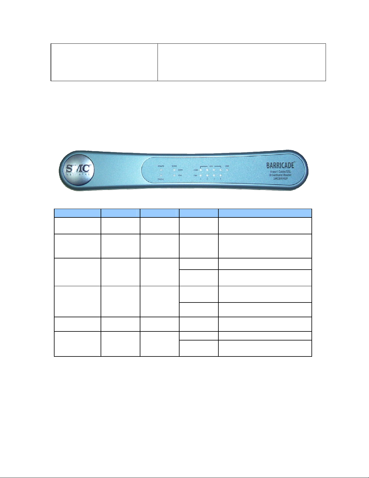
4 | Panel Layout
The following figure shows the front panel layout, which is followed by a table describing in detail the
status and function of each LED.
SMCBR14UP
LED Function Color Status Description
Power Power
indicator
M1 System
status
indicator
activity
Link/Act. 1–4 Link status Green
Speed 10/100 Data rate Green Steady Data is transmitted at 100 Mbps
Green Steady Power is being applied to this
device
Orange Blinking
Green
Steady The WAN port is connected WAN Wan port
Blinking
Steady An active station is connected to
Blinking
M1 is flashing once every
second to indicate that the
system has power
The WAN port is sending or
receiving data
the LAN port
The corresponding LAN port is
sending of receiving data
USB USB port
activity
SMCBR14UP Rear Panel: 4 LAN, 1 WAN, 1 USB, 1 PRINTER
Green
10
On The USB port is linked.
The USB port is sending or
Blinking
receiving data.
Page 11

Port Type Description
5 VDC Receptor for power adapter:
5 VDC, 2 A (minimum)
WAN This is the connection for the Ethernet cable to the
Ethernet port on the cable or DSL modem
Port 1–4 These are the connections for Ethernet cables to your
Ethernet enabled computers
USB USB Ports for USB printer
PRINTER DB25 Printer Port
5 | Hardware Installation
The router can be placed anywhere in your office or home. No special wiring or cooling
requirements are necessary. However, you should comply with the following guidelines:
• Place your router on a flat, horizontal surface
• Be sure to place your router away from any heating devices
• Avoid dusty and/or humid areas
1) Setup LAN Connection: Connect an Ethernet cable from your computer’s Ethernet port to one of
the LAN ports of the router.
2) Step WAN Connection: Insert one end of the Ethernet cable into the WAN port on the back panel
of your router, and the other end to the cable/DSL modem. You may connect an analog modem
(optional) to function as a backup connection.
3) Power Up: The router automatically enters the self-testing phase once the power cord is plugged
into a wall outlet. When in self-testing phase, the M1 indicator LED illuminates for about five
seconds to indicate proper connection. The M1 LED flashes twice as soon as the self-testing phase
is completed. After the completion of the self-testing phase, the M1 LED should flash once per
second to indicate that the router is functioning properly.
11
Page 12

6 | Network Settings and Software Installation
IP Address
Subnet Mask
Administrator Password
User Password
You must first verify that the TCP/IP communication protocol is properly installed and the computer is
configured to get its IP address via the DHCP Server that is built-into this router. If you have not previously
installed TCP/IP protocols on your client PCs, refer to the following section.
Default Settings
192.168.2.1
255.255.255.0
smcadmin
password
6.1 Installing TCP/IP
Windows 95/98/Me
1. Click Start/Settings/Control Panel.
2. Double-click the Network icon and select the Configuration tab in the Network window.
3. Click the Add button.
4. Double-click Protocol.
5. Select Microsoft in the manufacturers list. Select TCP/IP in the Network Protocols list. Click the
OK button to return to the Network window.
6. The TCP/IP protocol will be listed in the Network window.
7. Click OK. The operating system may prompt you to restart your system. Click Yes and the
computer will shut down and restart.
Windows 2000/XP
1. Click the Start button and choose Settings, then click the Network and Dial-up Connections icon.
2. Double-click the Local Area Connection icon, and click the Properties button on the General tab.
3. Click the install button.
4. Double-click Protocol.
5. Choose Internet Protocol (TCP/IP). Click the OK button to return to the Network window.
6. The TCP/IP protocol will be listed in the Network window. Click OK to complete the installation
procedure.
6.2 | Setting up TCP/IP
Windows 95/98/Me
You may find that the instructions here do not exactly match your version of Windows. This is because
these steps and screenshots were created in Windows 98. Windows 95 and Windows Millennium
Edition are very similar, but not identical, to Windows 98.
1. From the Windows desktop, click Start/Settings/Control Panel.
2. In the Control Panel, locate and double-click the Network icon.
3. On the Network window Configuration tab, double-click the TCP/IP entry for your network card.
4. Click the IP Address tab.
5. Click the “Obtain an IP address” option.
6. Next click on the Gateway tab and verify the Gateway field is blank. If there are IP addresses listed
in the Gateway section, highlight each one and click Remove until the section is empty.
7. Click the OK button to close the TCP/IP Properties window.
8. On the Network Properties Window, click the OK button to save these new settings. Note:
Windows may ask you for the original Windows installation disk or additional files. Check for the
files at c:\windows\options\cabs, or insert your Windows CD-ROM into your CDROM drive and
check the correct file location, e.g., D:\win98, D:\win9x. (if D: is the letter of your CD-ROM drive).
9. Windows may prompt you to restart the PC. If so, click the Yes button. If Windows does not prompt
you to restart your computer, do so to insure your settings.
12
Page 13

Windows NT
1. From the Windows desktop click Start/Settings/Control Panel.
2. Double-click the Network icon.
3. Click on the Protocols tab.
4. Double-click TCP/IP Protocol.
5. Click on the IP Address tab.
6. In the Adapter drop-down list, be sure your Ethernet adapter is selected.
7. Click on “Obtain an IP address from a DHCP server.”
8. Click OK to close the window.
9. Windows may copy files and will then prompt you to restart your system. Click Yes and your
computer will shut down and restart.
Windows 2000/XP
1. Access your Network settings by clicking Start, then choose Settings and then select Control
Panel.
2. In the Control Panel, locate and double-click the Network and Dial-up Connections icon.
3. Locate and double-click the Local Area Connection icon for the Ethernet adapter that is
connected to the Router. When the Status dialog box window opens, click the Properties button.
4. In the Local Area Connection Properties box, verify the box next to Internet Protocol (TCP/IP) is
checked. Then highlight the Internet Protocol (TCP/IP), and click the Properties button.
5. Select “Obtain an IP address automatically” to configure your computer for DHCP. Click the
OK button to save this change and close the Properties window.
6. Click the OK button again to save these new changes.
7. Reboot your PC.
6.3 | Obtaining an IP Address
Windows 95/98/Me
1. Click Start/Run.
2. Type WINIPCFG and click OK.
3. From the drop-down menu, select your network card. Click Release and then Renew.
Verify that your IP address is now 192.168.2.xxx, your Subnet Mask is 255.255.255.0 and your
Default Gateway is 192.168. 2.1. These values confirm that the Router is functioning. Click OK to
close the IP Configuration window.
Windows 2000/XP
1. On the Windows desktop, click Start/Programs/Command Prompt.
2. In the Command Prompt window, type IPCONFIG /RELEASE and press the <ENTER> key.
3. Type IPCONFIG /RENEW and press the <ENTER> key. Verify that your IP Address is now
192.168.2.xxx, your Subnet Mask is 255.255.255.0 and your Default Gateway is 192.168.2.254.
These values confirm that the Router is functioning
4. Type EXIT and press <ENTER> to close the Command Prompt window.
6.4 | Configuring a Macintosh Computer
You may find that the instructions here do not exactly match your screen. This is because these steps and
screen shots were created using Mac OS 10.2. Mac OS 7.x and above are all very similar, but may not be
identical to Mac OS 10.2.
1. Pull down the Apple Menu. Click System Preferences and select Network.
2. Make sure that Built-in Ethernet is selected in the Show field.
3. On the TCP/IP tab, select Using DHCP in the Configure field.
4. Close the TCP/IP dialog box.
13
Page 14

6.5 | Verifying Your TCP/IP Connection
After installing the TCP/IP communication protocols and configuring an IP address in the same network
as the Router, use the ping command to check if your computer has successfully connected to the Router.
The following example shows how the ping procedure can be executed in an MS-DOS window. First,
execute the ping command:
Ping 192.168.2.1
If a message similar to the following appears:
Pinging 192.168.2.1 with 32 bytes of data:
Reply from 192.168.2.1: bytes=32 time=2ms TTL=64
…a communication link between your computer and the Router has been successfully
established.
If you get the following message:
Pinging 192.168.2.1 with 32 bytes of data: Request
timed out.
…there may be something wrong in your installation procedure.
Check the following items in sequence:
1. Is the Ethernet cable correctly connected between the Router and the computer? The LAN LED on the
Router and the Link LED of the network card on your computer must be on.
2. Is TCP/IP properly configured on your computer? If the IP address of the Router is 192.168.2.1, the IP
address of your PC must be from 192.168.2.2 - 254 and the default gateway must be 192.168.2.1. If you
can successfully ping the Router you are now ready to connect to the Internet!
14
Page 15

7 | Configuring Your Broadband Router
Before you attempt to log into the web-based Administration, please verify the following.
1. Your browser is configured properly (see below).
2. Disable any firewall or security software that may be running.
3. Confirm that you have a good link LED where your computer is plugged into the Router. If you
don’t have a link light, then try another cable until you get a good link.
7.1 | Browser Configuration
Confirm your browser is configured for a direct connection to the Internet using the Ethernet cable that is
installed in the computer. This is configured through the options/preference section of your browser.
You will also need to verify that the HTTP Proxy feature of your web browser is disabled. This is so that
your web browser will be able to view the Router configuration pages. The following steps are for Internet
Explorer and for Netscape. Determine which browser you use and follow the appropriate steps.
Internet Explorer 5 or above (For Windows)
1. Open Internet Explorer. Click Tools, and then select Internet Options.
2. In the Internet Options window, click the Connections tab.
3. Click the LAN Settings button.
4. Clear all the check boxes and click OK to save these LAN settings changes.
5. Click OK again to close the Internet Options window.
Internet Explorer (For Macintosh)
1. Open Internet Explorer. Click Explorer/Preferences.
2. In the Internet Explorer Preferences window, under Network, select Proxies.
3. Uncheck all check boxes and click OK.
7.2 | Web Management
To access the Router’s management interface, enter the Router IP address in your web browser
http://192.168.2.1.
Note that there are two different Web user interfaces, one for general users and one for the system
administrator. To log on as an administrator, enter the system password (default password is smcadmin)
and click the LOGIN button. If you typed the password correctly, the left panel of the Web user interface
changes to the administrator configuration mode as shown in the following figures.
15
Page 16

7.3 | Setup Wizard
7.3.1 Time Zone
After logging into the web management, click on SETUP WIZARD on the top left navigation panel. The
first item is Time Zone. For accurate timing of client filtering and log events, you need to set the time zone.
Select your time zone from the drop-down list.
7.3.2 Broadband Type
The following screen lets you select a WAN type. Click one of the five options and then click [Next].
16
Page 17

7.3.4 Cable Modem
The cable modem option allows you to configure a host name and MAC Address. The Host Name is
optional, but may be required by some ISPs. The default MAC address is set to the WAN’s physical
interface on the Router. Use this address when registering for Internet service, and do not change it unless
required by your ISP. If your ISP used the MAC address of an Ethernet card as an identifier when first
setting up your broadband account, only connect the PC with the registered MAC address to the Router and
click the Clone MAC Address button. This will replace the current Router MAC address with the already
registered Ethernet card MAC address. If you are unsure of which PC was originally set up by the
broadband technician, call your ISP and request that they register a new MAC address for your account.
Register the default MAC address of the Router.
7.3.5 Fixed-IP xDSL
Some xDSL Internet Service Providers may assign a fixed (static) IP address. If you have been provided
with this information, choose this option and enter the assigned IP address, gateway IP address, DNS IP
addresses, and subnet mask.
17
Page 18

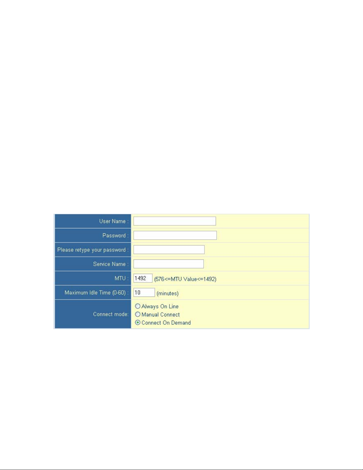
7.3.6 PPPoE xDSL
Enter the PPPoE User Name and Password assigned by your Service Provider. The Service Name is
normally optional, but may be required by some service providers. Leave the Maximum Transmission Unit
(MTU) at the default value unless you have a particular reason to change it. Enter a Maximum Idle Time
(in minutes) to define a maximum period of time for which the Internet connection is maintained during
inactivity. If the connection is inactive for longer than the Maximum Idle Time, it will be dropped.
(Default: 10) Configure the Connect mode option to the desired settings. “Always On Line” signifies that
the broadband router will maintain your Internet connection consistently and automatically connect to the
Internet after any disconnection. “Manual Connect” signifies that the broadband router will establish an
Internet connection only when the administrator logs into the web management and manually presses the
“Connect” button. While using the “Connect On Demand” option, if the connection is inactive for longer
than the Maximum Idle Time, it will be dropped and will automatically re-establish the connection as soon
as you attempt to access the Internet again.
18
Page 19

7.3.7 PPTP
Point-to-Point Tunneling Protocol is a common connection method used for xDSL connections in Europe.
It can be used to join different physical networks using the Internet as an intermediary. If you have been
provided with the information as shown on the screen, enter the assigned IP address, subnet mask, default
gateway IP address, user ID and password, and PPTP Gateway. Configure the Connect mode option to the
desired settings. “Always On Line” signifies that the broadband router will maintain your Internet
connection consistently and automatically connect to the Internet after any disconnection. “Manual
Connect” signifies that the broadband router will establish an Internet connection only when the
administrator logs into the web management and manually presses the “Connect” button. While using the
“Connect On Demand” option, if the connection is inactive for longer than the Maximum Idle Time, it will
be dropped and will automatically re-establish the connection as soon as you attempt to access the Internet
again.
7.3.8 BigPond
If you use the BigPond Internet Service which is available in Australia, enter your username and password
and apply the changes.
19
Page 20

7.3.9 L2TP
Layer 2 Tunneling Protocol is a common connection method used for xDSL connections in Europe. It can
be used to join different physical networks using the Internet as an intermediary. If you have been provided
with the information as shown on the screen, enter the assigned IP address, subnet mask, default gateway
IP address, user ID and password, and L2TP Gateway. Configure the Connect mode option to the desired
settings. “Always On Line” signifies that the broadband router will maintain your Internet connection
consistently and automatically connect to the Internet after any disconnection. “Manual Connect” signifies
that the broadband router will establish an Internet connection only when the administrator logs into the
web management and manually presses the “Connect” button. While using the “Connect On Demand”
option, if the connection is inactive for longer than the Maximum Idle Time, it will be dropped and will
automatically re-establish the connection as soon as you attempt to access the Internet again.
20
Page 21

7.4 | Advanced Setup – SYSTEM
7.4.1 Time Zone
Use the section below to configure the Barricade's system time. Select your time zone and configure
the daylight savings option based on your location. This information is used for the time/date parental
rules you can configure with the Barricade's Advanced Firewall. This information is also used for your
network logging.
Once you set you time zone, you can automatically update the Barricade's internal clock by synchronizing
with a public time server over the Internet. To configure this setting, choose one of the options below - each
option allows a different method of updating.
21
Page 22

7.4.2 Password Settings
Use this section to configure the 2 password accounts and idle time-out setting for your Barricade Router.
There are 2 levels of admin access for this Router:
The Administrator account has Read/Write permission to view and change any settings. The default
password for this account is "smcadmin".
The User account has Read-Only permissions to view but not change the settings. The default password
for this account is "password".
7.4.3 Remote Management
Use this section to configure the remote management feature of your Barricade Router so the webmanagement can be accessed from the Internet (WAN). You can restrict access to a single IP or a range of
IP addresses. If the specified IP address is 0.0.0.0, any host can connect to the router to perform these tasks.
You can use the subnet mask bits’ /nn notation to specify a group of trusted IP addresses. For example,
10.1.2.0/24. You can also change the remote port that the administrator uses to gain access to the web
management.
22
Page 23

7.4.4 Syslog Server
The Syslog Server tool will automatically download the Barricade log to the server IP address specified by
the user. Enter the Server LAN IP Address and select the Enable radio button to enable this function. The
broadband router is also able to send the log files to a specific email address. Simply enter the IP address of
your mail server in the SMTP Server box, enter the email addresses of the recipients who will receive the
email log, and put in your username and password. Note that you can also customize the subject title of the
email! Check to be sure the radio button for Enable is checked and then submit the changes.
23
Page 24

7.5 | Advanced Setup - WAN
7.5.1 Dynamic IP
The cable modem option allows you to configure a host name and MAC Address. The Host Name is
optional, but may be required by some ISPs. The default MAC address is set to the WAN’s physical
interface on the Router. Use this address when registering for Internet service, and do not change it unless
required by your ISP. If your ISP used the MAC address of an Ethernet card as an identifier when first
setting up your broadband account, only connect the PC with the registered MAC address to the Router and
click the Clone MAC Address button. This will replace the current Router MAC address with the already
registered Ethernet card MAC address. If you are unsure of which PC was originally set up by the
broadband technician, call your ISP and request that they register a new MAC address for your account.
Register the default MAC address of the Router.
24
Page 25
7.5.2 PPPoE
Enter the PPPoE User Name and Password assigned by your Service Provider. The Service Name is
normally optional, but may be required by some service providers. Leave the Maximum Transmission Unit
(MTU) at the default value unless you have a particular reason to change it. Enter a Maximum Idle Time
(in minutes) to define a maximum period of time for which the Internet connection is maintained during
inactivity. If the connection is inactive for longer than the Maximum Idle Time, it will be dropped.
(Default: 10) Configure the Connect mode option to the desired settings. “Always On Line” signifies that
the broadband router will maintain your Internet connection consistently and automatically connect to the
Internet after any disconnection. “Manual Connect” signifies that the broadband router will establish an
Internet connection only when the administrator logs into the web management and manually presses the
“Connect” button. While using the “Connect On Demand” option, if the connection is inactive for longer
than the Maximum Idle Time, it will be dropped and will automatically re-establish the connection as soon
as you attempt to access the Internet again.
25
Page 26

7.5.3 PPTP
Point-to-Point Tunneling Protocol is a common connection method used for xDSL connections in Europe.
It can be used to join different physical networks using the Internet as an intermediary. If you have been
provided with the information as shown on the screen, enter the assigned IP address, subnet mask, default
gateway IP address, user ID and password, and PPTP Gateway. Configure the Connect mode option to the
desired settings. “Always On Line” signifies that the broadband router will maintain your Internet
connection consistently and automatically connect to the Internet after any disconnection. “Manual
Connect” signifies that the broadband router will establish an Internet connection only when the
administrator logs into the web management and manually presses the “Connect” button. While using the
“Connect On Demand” option, if the connection is inactive for longer than the Maximum Idle Time, it will
be dropped and will automatically re-establish the connection as soon as you attempt to access the Internet
again.
26
Page 27

7.5.4 Static IP
Some Internet Service Providers may assign a fixed (static) IP address. If you have been provided with this
information, choose this option and enter the assigned IP address, gateway IP address, DNS IP addresses,
and subnet mask.
7.5.6 BigPond
If you use the BigPond Internet Service which is available in Australia, enter your username and password
and apply the changes.
27
Page 28

7.5.7 L2TP
Layer 2 Tunneling Protocol is a common connection method used for xDSL connections in Europe. It can
be used to join different physical networks using the Internet as an intermediary. If you have been provided
with the information as shown on the screen, enter the assigned IP address, subnet mask, default gateway
IP address, user ID and password, and L2TP Gateway. Configure the Connect mode option to the desired
settings. “Always On Line” signifies that the broadband router will maintain your Internet connection
consistently and automatically connect to the Internet after any disconnection. “Manual Connect” signifies
that the broadband router will establish an Internet connection only when the administrator logs into the
web management and manually presses the “Connect” button. While using the “Connect On Demand”
option, if the connection is inactive for longer than the Maximum Idle Time, it will be dropped and will
automatically re-establish the connection as soon as you attempt to access the Internet again.
28
Page 29

7.6 | Advanced Setup - LAN
This is the local IP address of the router. All networked computers must use the LAN IP address of the
router as their default Gateway. However, if necessary, it can be changed. Here you can configure the LAN
IP address for the router and enable/disable the DHCP server for dynamic client address allocation. You
can change the lease time if necessary as well. By default this is set to “One Week”. The other options are
Half Hour, One Hour, Two Hours, Half Day, One Day, Two Days, and Forever. “Forever” signifies that
there is no time limit on the IP address lease.
For the IP address pool, a dynamic IP address range may be specified (Default: 192.168.2.100-199). Once
the IP addresses, e.g. 192.168.2.100–199, have been assigned, these IP addresses will be part of the
dynamic IP address pool. IP addresses from 192.168.2.2–99, and 192.168.2.200–254 will be available as
static IP addresses. Remember not to include the address of the Router in the client address pool. Also
remember to configure your client PCs for dynamic IP address allocation. Lastly, you can enter a local
domain suffix in the Domain Name field.
You also have the option to configure more advanced settings by clicking the “More” button. You can
configure the router’s DHCP server to give out specific Primary and Secondary DNS, Primary and
Secondary WINS, and an alternate Gateway (in the event that the router is not the Internet gateway).
29
Page 30

Clicking on the “Client List” link brings up the DHCP Client Table, showing all the clients that have
obtained DHCP addresses from the router:
7.7 | Advanced Setup - NAT
7.7.1 | Virtual Server
The firewall of the router filters out unrecognized packets to protect your intranet. This means that all
network hosts are invisible to the outside world. However, some of the hosts can be made accessible by
enabling the Virtual Server mapping. A virtual server is defined as a Service Port. All requests to this port
will be redirected to the computer specified by the Server IP. The virtual server can work with scheduling
rules as well. This gives you more flexibility for access control.
30
Page 31

For example, if you have an FTP server (port 21) at 192.168.123.1, a Web server (port 80) at
192.168.123.2, and a server at 192.168.123.6, you need to specify the following virtual server mapping as
shown in the table below:
Service Port Server IP Enable
21 192.168.123.1 X
80 192.168.123.2 X
1723 192.168.123.6 X
The “IP Address” section should contain the IP of the server computer in the LAN network that will be
providing the virtual services. The “Public Port” is the port number or port range on the WAN side that
will be used to access the virtual service. The “Private Port” is the port number of the service used by the
server computer. “Data Type” can be User Datagram Protocol (UDP), Transmission Control Protocol
(TCP) or both. This depends on the type of service you are running. TCP is connection-oriented protocol
and UDP is connectionless. Since most services are connection-oriented, you will most likely need to
select TCP. For example, FTP and HTTP are connection-oriented services while DNS and many
streaming radio servers are connectionless.
7.7.2 | Special Applications
Some applications require multiple connections, such as Internet games, video conferencing, and
Internet telephony. These applications cannot work with a pure NAT router because of the
firewall function. However, the Special Applications feature allows some of these applications to
work with the router. Should the Special Applications feature fail to make an application work,
you can try setting your computer as a DMZ host.
Trigger: This is the outbound port number issued by the application.
Incoming Ports: When the trigger packet is detected, the inbound packets sent to specified
port numbers are allowed to pass through the firewall.
31
Page 32
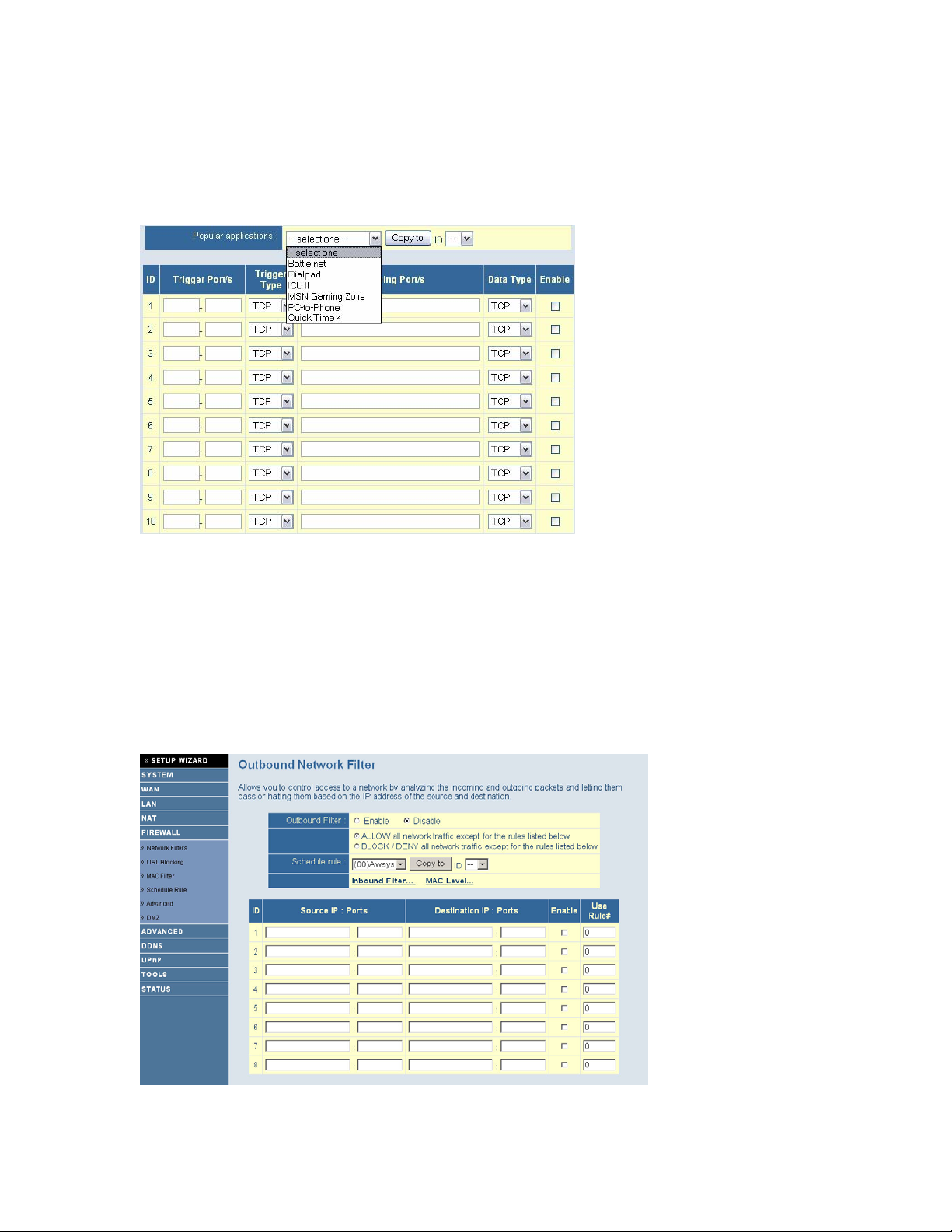
The router provides some predefined settings. To add a predefined setting to your list, select an
application and click “Copy to”.
Note: Only one computer can use the Special Application tunnels at any given time.
For a full list of ports and the services that run on them, see http://www.iana.org/assignments/port-numbers
7.8 | Advanced Setup - FIREWALL
7.8.1 | Network Filters
The Broadband Router firewall includes comprehensive Outbound and Inbound Network Packet Filters.
The firewall does not significantly affect system performance. The packet filter lets you control which
packets are allowed to pass through the router. The Outbound Filter applies to all outbound packets. The
Inbound Filter applies only to packets addressed to a virtual server or DMZ host.
You can select one of the two filtering policies:
• Allow all to pass except those that match the specified rules
• Deny all to pass except those that match the specified rules
32
Page 33

You can apply up to 8 rules for each direction, inbound or outbound. For each rule you can define
the following:
• Source IP address
• Source port address
• Destination IP address
• Destination port address
• Protocol: TCP or UDP, or both
• Use Rule #
You can define a single IP address (4.3.123.254) or a range of IP addresses (4.3.123.254 – 4.3.2.254) for
the source or destination IP address. A blank IP implies that all IP addresses are included. You can define a
single port (80) or a range of ports (1000 – 1999) for the source or destination port. Specify the TCP or
UDP protocol by adding the prefix T or U. Not adding a prefix implies all ports. Each rule can be enabled
or disabled.
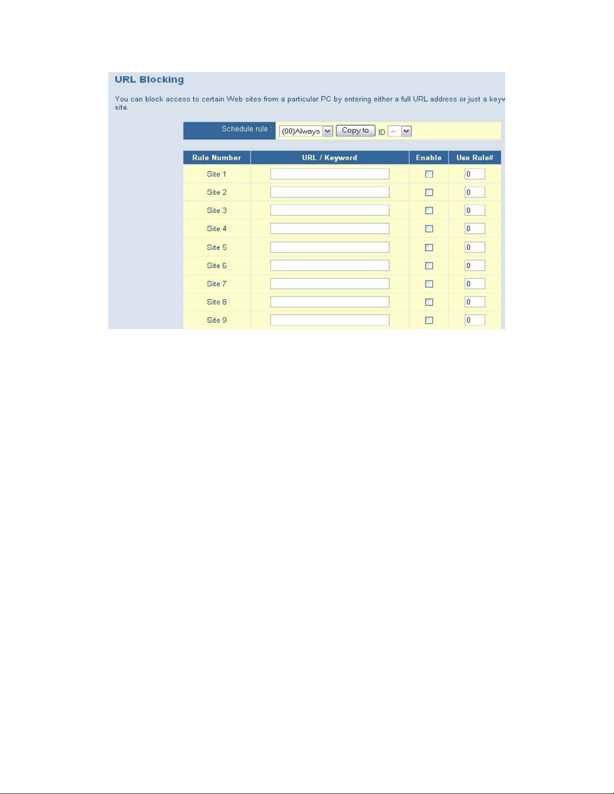
7.8.2 | URL Blocking
URL Blocking blocks LAN computers from accessing pre-defined Websites. The difference between the
Domain Filter and URL Blocking is that the Domain filter requires you to enter a suffix (.com or .org),
while URL Blocking requires you to enter only a keyword. In other words, the Domain Filter can block
specific Websites, while URL Blocking can block hundreds of Websites simply by using a keyword.
• URL Blocking: Check the box next to Enable if you want to enable the URL Blocking option.
• URL / Keyword: If any part of a Website’s URL matches the pre-defined word you have
entered here, the connection will be blocked. For example, if you type the word “firewall” into
the URL text field, all URLs containing that word will be blocked.
• Enable: Check the box to enable the rules.
• Use Rule #: Applies a configured schedule rule
33
Page 34
7.8.3 | MAC Filter
MAC Address Filtering allows you assign different access rights to various users and you can also assign a
specific IP address to a certain MAC address.
Select the Enable radio button to enable the MAC Address Control. All of the settings on this screen take
effect when Enable is checked.
• MAC Address: This is the unique address of a specific client.
• IP Address: Expected IP address of the corresponding client. You can keep this text field blank if
you do not know the address.
The DHCP pull-down menu lets you select specific clients.
Select clients from the DHCP clients list and click “Copy to”, to copy the MAC addresses to the
selected ID, chosen from the ID pull-down menu.
• Previous Page / Next Page: Use these links to navigate to different pages. The router
supports up to 32 MAC filters.
34
Page 35

7.8.4 | Schedule Rule
Set scheduled times to be used to control what time of day a service or set of services is enabled. Use this
section to configure up to 10 Schedule Rules to limit network access based on time and day. To create a
schedule rule click the [Add Schedule Rule...] link below.
Enter a rule name into the text field next to “Name of Rule 1”. Click Save Settings to save your settings.
35
Page 36

The Schedule Rule screen appears. It now shows your setting for Rule 1. If you need to make changes to
your setting, click the Edit button. If you want to delete Rule 1, click the Delete button.
7.8.5 | Advanced
In this section you can enable/disable Stateful Packet Inspection (SPI), Discard Ping from WAN, and PPTP
and IPSec Passthrough types.
When Discard Ping From WAN is enabled, computers on the Internet will not get a reply back from the
Broadband Router when it is being “ping”ed. This may help to increase security.
When SPI is enabled, the router will extensively record specific packet information passed through the
router such as IP address, port address, ACK, and so on. The router will also check every incoming packet
to detect its validity.
36
Page 37
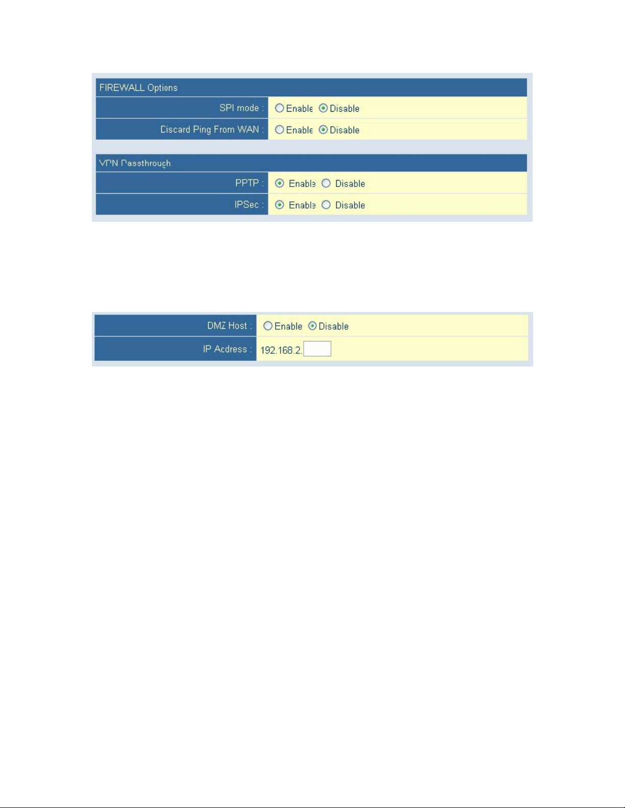
7.8.6 | DMZ
If you have a local client PC that cannot run an Internet application properly from behind the NAT firewall,
then you can open the client up to unrestricted two-way Internet access by defining a Virtual DMZ Host.
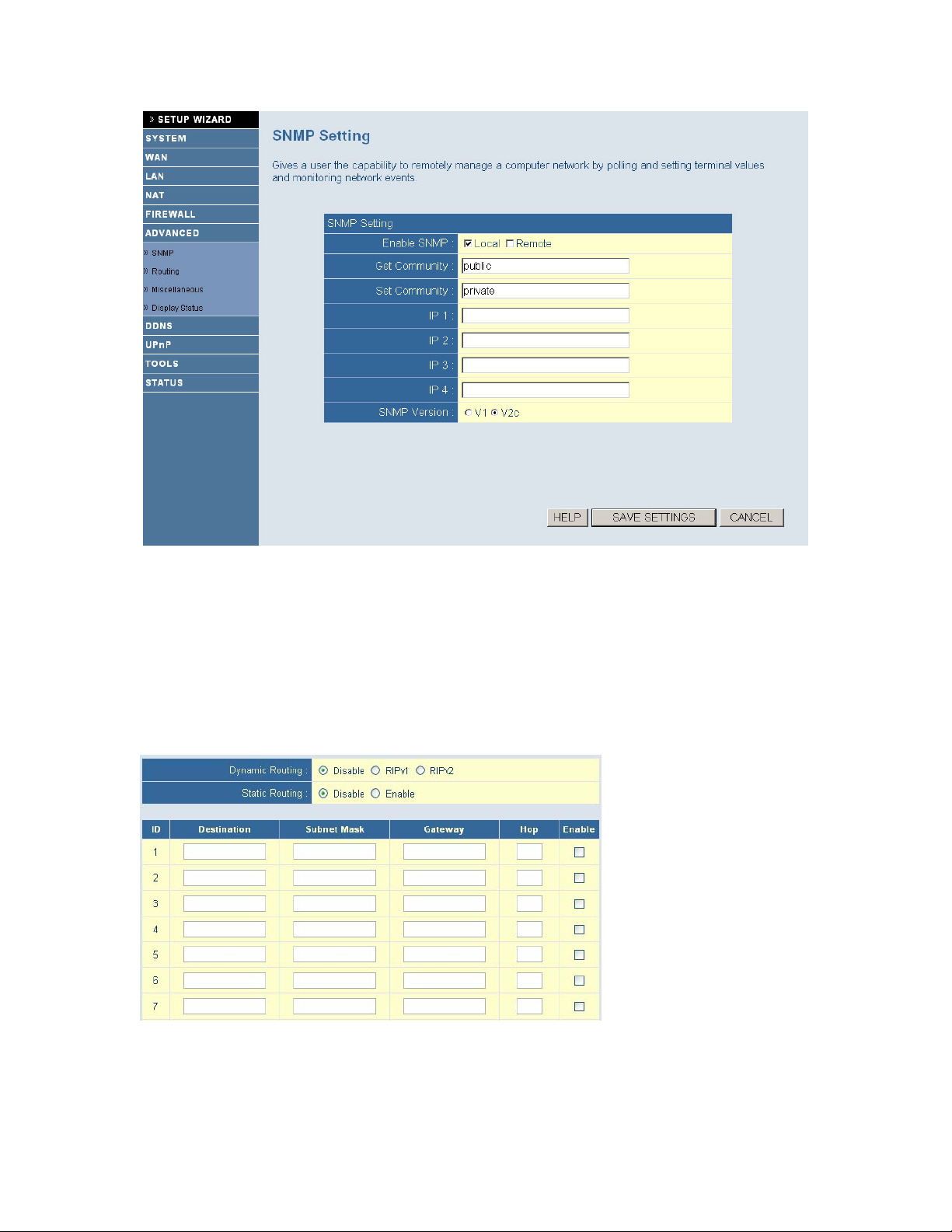
7.9 | Advanced Setup - SNMP
The Simple Network Management Protocol (SNMP) lets you manage a computer network remotely by
polling and setting terminal values and monitoring network events.
• Enable SNMP: You can check Local, Remote, or both options to enable the SNMP function.
{ If Local is checked, the router responds only to requests from the LAN.
{ If Remote is checked, the router responds only to requests from the WAN.
• Get Community: Setting this option allows the router respond to a request.
• Set Community: Setting this option allows your router to accept a request.
37
Page 38
7.10 | Advanced Setup - ROUTING
The Routing Table lets you determine which physical interface address to use for outgoing IP data grams.
If you have more than one router and subnet, you will have to enable the routing table to allow packets to
find the routing path. This allows different subnets to communicate with each other. The settings in the
routing table are used to support static and dynamic routing functions. RIPv1 is a protocol where the IP
address is routed through the Internet. RIPv2 is an enhanced version of RIP v1 with added features such as
Authentication, Routing Domain, Next Hop Forwarding, and Subnet Mask Exchange.
Enable Static Routing by selecting the radio button next to Enable.
• Static Routing: Allows you to specify up to 8 routing rules. You can enter the destination IP
address, subnet mask, gateway, hop for each routing rule, and then enable or disable the rule by
toggling the Enable check box. Once the routing table settings are configured, click Save.
38
Page 39
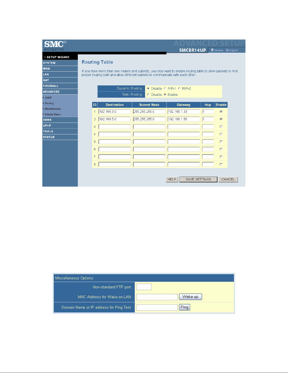
Example:
7.11 | Advanced Setup - MISCELLANEOUS
If you experience difficulties accessing an FTP server that is running on a port other than 21, you can enter
that port in the “Non-standard FTP port” and apply the changes.
Wake-on-LAN is a technology that lets you power up a networked router remotely. To use this feature,
the target network adapter must be Wake-on-LAN enabled and you have to know the MAC address of
the adapter. The address should look similar to this: 00-11-22-33-44-55. Depressing the “Wake up”
button tells the router to send the wake-up frame to the target adapter.
The ping diagnostics feature allows you to configure an IP address to ping from the router. You can ping a
specific IP or domain to test whether the router is active.
39
Page 40
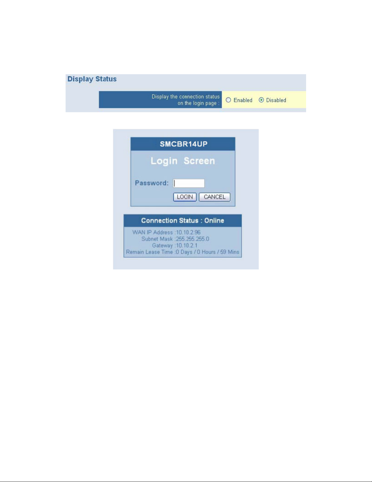
7.12 | Advanced Setup – DISPLAY STATUS
Enable the Display Status option to view the WAN connectivity settings on the login page.
When this is enabled, the login page appears as follows:
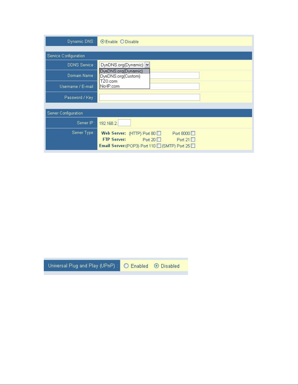
7.13 | DDNS (Dynamic DNS)
Dynamic DNS provides users on the Internet a method to tie their domain name(s) to computers or servers.
DDNS allows your domain name to follow your IP address automatically by having your DNS records
changed when your IP address changes. Before you can enable the Dynamic DNS, you need to register an
account with one of the Dynamic DNS servers that are listed in the Provider field.
40
Page 41
7.14 | UPnP (Universal Plug-and-Play)
The Universal Plug and Play architecture offers pervasive peer-to-peer network connectivity of PCs of all
form factors, intelligent appliances, and wireless devices. UPnP enables seamless proximity networking in
addition to control and data transfer among networked devices in the home, office and everywhere in
between.
Enable UPnP by checking ON in the screen above. UPnP allows the device to automatically:
• dynamically join local network
• obtain an IP address
• convey its capabilities and learn about the presence and capabilities of other devices.
Dynamically open ports for UPnP aware software, such MSN messenger advanced features (voice, remote
control).
7.15 | Tools
The Toolbox menu allows you to view your system logs, upgrade firmware, backup settings, restore
settings to defaults, reboot the router, and access miscellaneous settings.
41
Page 42

7.16 | Status
You can use the Status screen to see the connection status for Barricade's WAN/LAN interfaces, firmware
and hardware version numbers, any illegal attempts to access your network, as well as information on all
DHCP client PCs currently connected to your network.
42
Page 43

8 | LPR Printing Guide
8.1 | Installing a LPR Print Server on Windows XP and Windows 2000
NOTE
• These instructions assume that the printer has previously been installed on the computer. This is
necessary to ensure that the printer drivers have been installed and are working correctly.
• Screen shots shown have been taken from Windows XP but differ only slightly from those used in
Windows 2000. The instructions will highlight any important differences.
Step 1 – Printers and Faxes Dialogue
First display the Printers and Faxes dialogue by selecting Start->Control Panel->Printers and Faxes. Use
Start->Settings->Control Panel->Printers and Faxes if you are using Windows 2000 or Windows XP in
Classic mode.
Next, in Windows XP, select Add a Printer from the left hand pane of the window or Right Click on the
right hand pane and select Add Printer. In Windows 2000 you must double-click on the Add Printer icon.
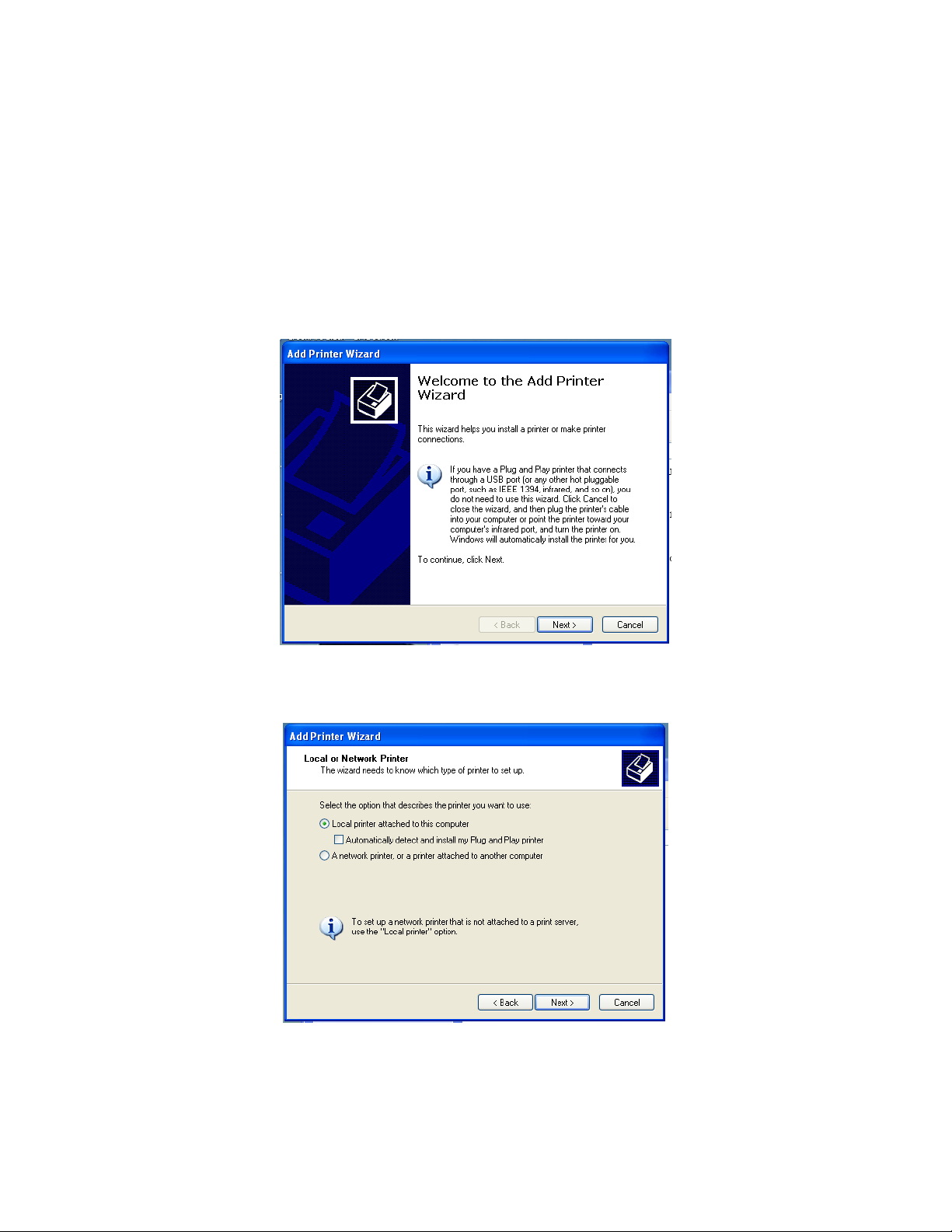
The following dialogue will be displayed:
Press Next to move to the next step.
43
Page 44

Step 2 – Select Local Printer
Select Local Printer and make sure Automatically detect and install my Plug and Play printer is NOT
selected.
Press Next to move on.
Step 3 – Create a new printer port
This dialogue is critical to the operation of the Print Server. The Windows 2000 page looks very different
but provides exactly the same options.
Select Create a new port and select Standard TCP/IP Port from the Type of Port list.
Press Next to launch the wizard that sets up the TCP/IP port.
44
Page 45

Press Next again.
Step 4 – Add Port
The Add Port dialogue will appear:
Enter the IP address of the Print Server in the Printer Name or IP Address field. The default address of
your router should be 192.168.2.1 as shown on the dialogue above. The Port Name is automatically
generated as the IP Address is entered but it can be changed to something more meaningful.
Press Next
45
Page 46

Step 5 – Custom Settings
he Additional Port Information dialogue will appear. Select Custom and then press the Settings... button.
T
he following dialogue will appear to allow you to set the protocol and Queue Name.
T
The Queue should be entered as LP for a DB25 (parallel) printer or LPUSB for a USB printer.
Check the LPR Byte Counting
Press OK to continue.
46
Page 47

This will return you to Additional Port Information dialogue. Press Next to display the following:
Press Finish to close t
he wizard.
tep 6 – Select Printer Driver
S
A page will be di er for
e printer.
th
splayed similar to that shown below which allows the selection of the correct driv
47
Page 48
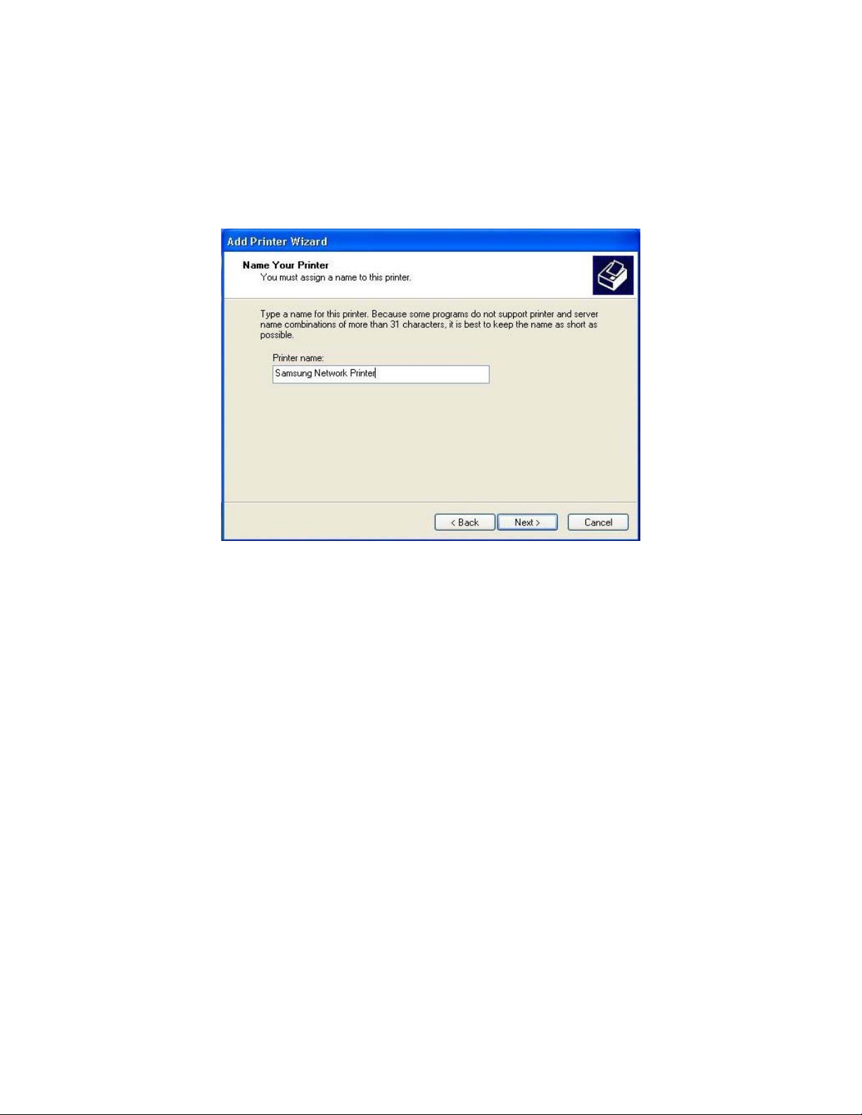
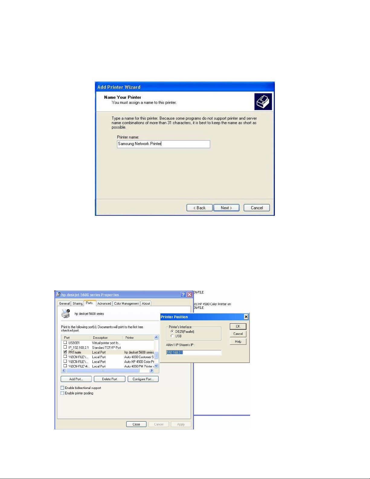
Step 7 – Changing the Printer Name.
When the correct driver has been selected or installed from disk, pressing Next will step through to the
Printer Name screen.
Selecting a mem
ress Next will step through the rest of the wizard.
P
orable name for the printer is recommended.
tep 8 - Finishing and printing a test page
S
ther pages should be left as the values that appear automatically however it is strongly recommended that
O
you print a Test Page.
Pressing Finish at the end of the wizard will finish the installation and a test page will be printed if that was
selected.
NOTE – If the test page does not print, please restart your computer and try again.
48
Page 49
8.2 | Installing the Print Server Monitor for Windows XP, 2000, NT
OTE
N
• These instructions assume that the printer has previously been installed on the computer. This is
necessary to ensure that the printer drivers have been installed and are working
• Screen shots shown have been taken from Windows XP but differ only slightly
indows 2000. The instructions will highlight any important differences.
W
correctly.
from those used in
Inst li
al ng the Printer Monitor Software
Step 1 –
O
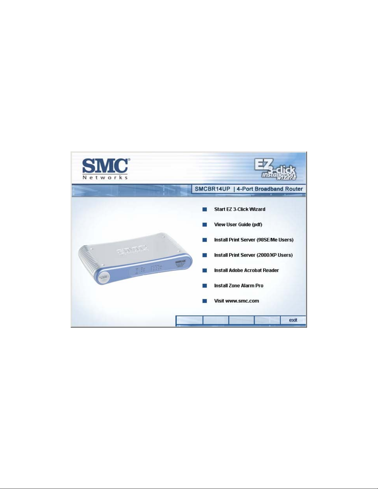
Insert the CD
nce inserted the CD will load automatically and display a screen similar to that shown below.
Step 2 – Select Install Printer Drivers
Select Install Printer Server (2000/XP Users). This will load another window.
This will load the printer port software required to op ate the print server from Windows XP, 2000, NT.
er
Step 3 – Installing the Software
Follow the three simple pages of the installation wizard. No information is required to be entered.
Press Finish on the last screen to comp
lete the wizard and return to the previous screen.
Step 4 – Restart your computer
49
Page 50
Adding a new printer
Step 1 – Printers and Faxes Dial
ogue
First display the Printers an
Start->Settings->Control P
lassic mode.
C
Next, in Windows XP, select Add a Printer f
ght hand pane and select Add Printer. In Windows 2000 you must double-click on the Add Printer icon.
ri
The following dialogue will be displayed:
d Faxes dialogue by selecting Start->Control Panel->Printers and Faxes. Use
anel->Printers and Faxes if you are using Windows 2000 or Windows XP in
rom the left hand pane of the window or Right Click on the
Press Next to move to the next step.
Step 2 – Select Local Printer
Select Local Printer and make sure Automatically detect and install my Plug and Play printer is NOT
selected.
Press Next to move on.
50
Page 51

Step 3 Select PTR mate port
Step 4 – Select Printer Driver
A page will be displayed similar to that shown below which allows the selection of the correct driver for
the printer.
51
Page 52
Step 5 – Changing the Printer Name.
When the correct driv
Printer Name screen.
er has been selected or installed from disk, pressing Next will step through to the
Selecting a memorable name for the printer is recommended.
Press Next will step thro
ugh the rest of the wizard.
Step 6: Choose appropriate printing method
Go to Start->Settin rinter. If the
default IP address of t
gs->Printers and configure the PRT mate port for your USB or parallel p
he router (192.168.2.1) has changed, please modify it accordingly.
52
Page 53

8.3 | Installing the Printer Server on Windows 98/SE/ME
NOTE
• These instructions assume that the printer has previously been installed on the computer.
• This is necessary to ensure that the printer drivers have been installed and are working correctly.
• Screen shots shown have been taken from Windows Me. Windows 98 and Windows SE screens
may differ slightly from those shown
Installing the Printer Monitor Software
Step 1 – Insert the CD
Once inserted the CD will automatically load and display a screen similar to that shown below.
Step 2 – Select Install Printer Drivers
Select Install Print Server (98SE/ME Users). This will load another window.
This will load the printer port software required to operate the print server from Windows 98/ME/SE.
Step 3 – Installing the Software
Follow the three simple pages of the installation wizard. No information is required to be entered.
Press Finish on the last screen to complete the wizard and return to the previous screen.
Step 4 – Restart your computer.
53
Page 54
Adding a new printer
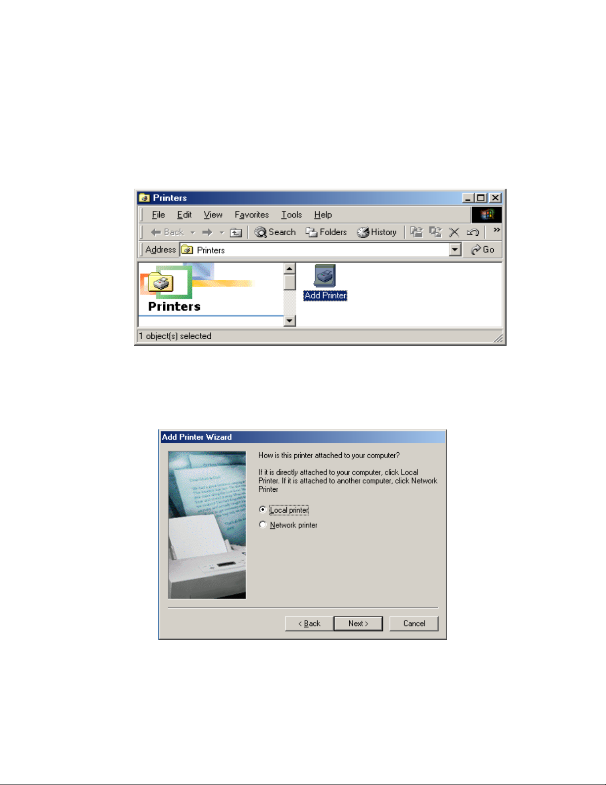
Step 1 - Display Printers
Display the Printers dialogue by selecting Start->Settings->Control Panel->Printers
An example of this window is shown below.
Step 2 – Add Printer
Click on Add Printer. This will load a wizard which ill install a new printer on the computer.
Press Next on the first screen and then the scre
w
en below will be displayed.
elect Local printer and then press Next to move on.
S
54
Page 55
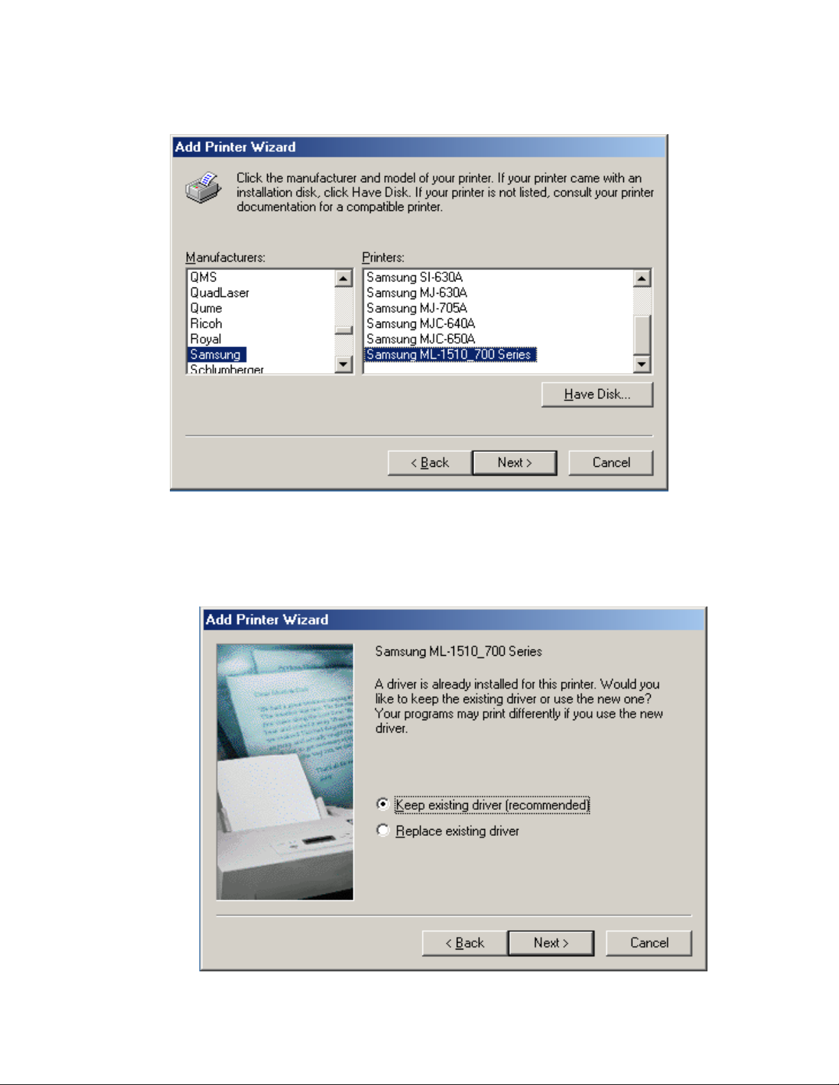
Step 3 – Select printer
Select the co
Since the printe e correct
driver. The exist
rrect driver for the printer and then press Next to move on.
r should have been previously installed the wizard will confirm that this is th
ing driver should be kept and then Next should be pressed.
55
Page 56
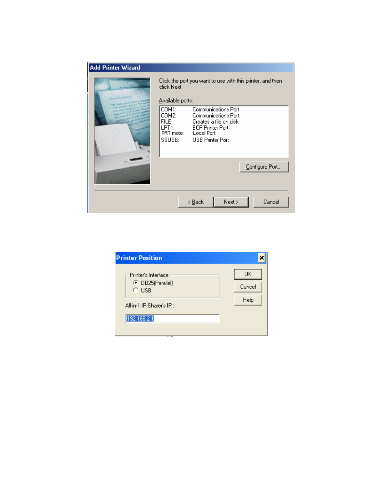
Step 4 – Port selection
fter installing the Printer Port Monitor at the start of this guide a PTR mate Port will now be available. A
Select the PTR mate Port and then press Configure Port...
tep 5 – Configure Port S
The IP Addres
Press OK to
move on.
56
s should be 192.168.2.1 (default) and the appropriate printer interface for your printer.
Page 57

Step 6 – Printer Name
nter a memorable Printer name. Press Next to move on. E
Step 7 – Print a Test Page
is recommended that a test page is printed.
It
ress Finish to complete the printer setup and this will also send the test page to the printer.
P
NOTE – If the test page d
document.
oes not print restart your computer before reading the troubleshooting
57
Page 58

8.4 |
Installing an LPR Print Server on Linux
NOTE – The rent Linux
distributions formation
that you will
Que
Que
Host:
screenshots shown below were produced on the KDE desktop of SuSE 9.1. Diffe
will have different screens but the functionality will be similar. In summary, the in
have to provide is as follows
ue type: LPD
ue name: LP for DB25 (parallel) printer or LPUSB for USB printer
192.168.2.1
NOTE – ng the
installation. do the
installation.
Printers MUST be installed by user ROOT so you must login as ROOT before starti
If no ROOT access is available then you must ask your system administrator to
Detailed step
s for Print Server Installation
Step 1 - Starting the Printer Configuration
Open
the Control Center, select Peripherals then select Printers.
Select Add Printer from within the window that appears.
Step 2 - Add Printer Wizard
After selecting Add Prin
ter the following screen will appear:
58
Page 59
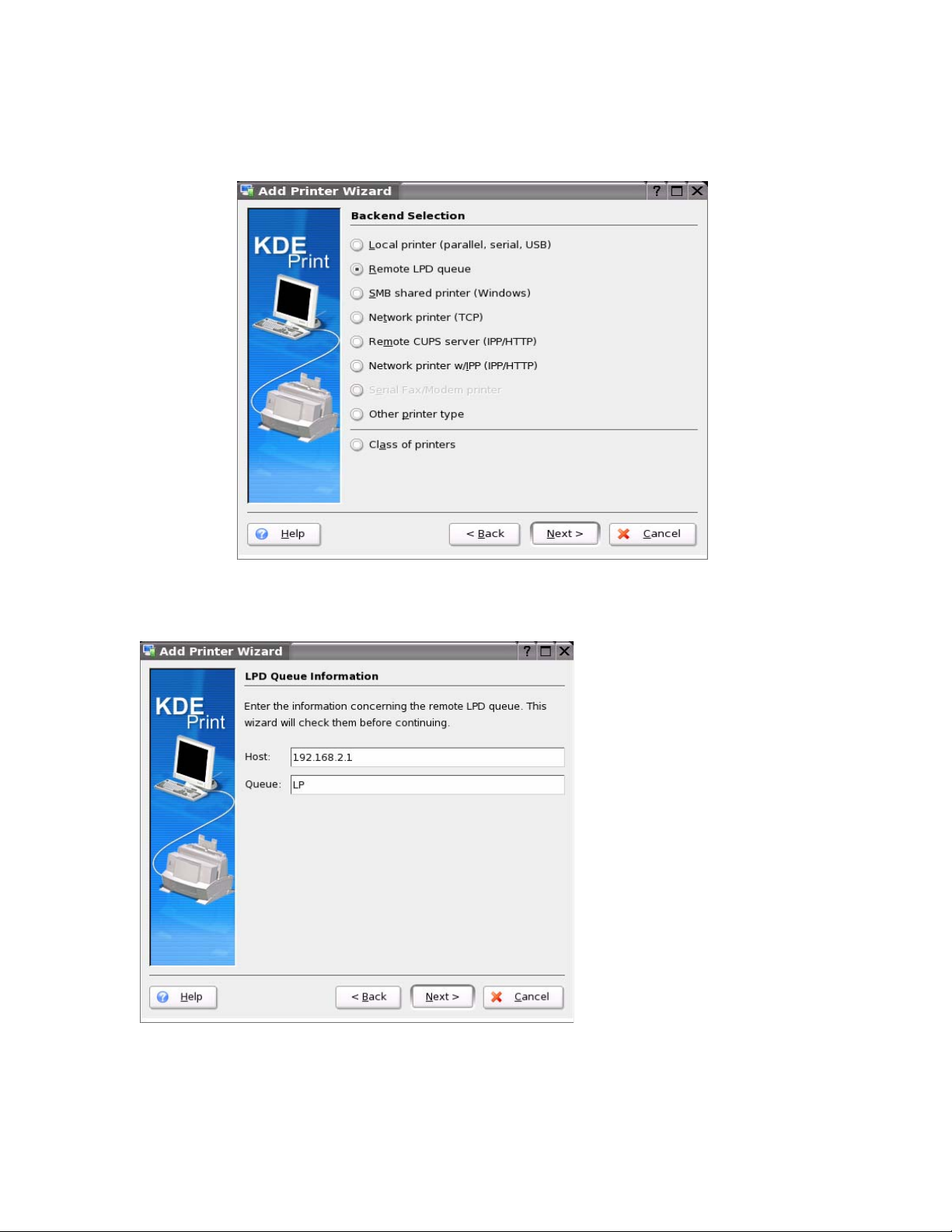
Step 3 – Select Queue type
The following screen will appear:
Select Remote LPD Queue as shown above then press Next to continue
Step 4 – Enter Hos t and Queue information
The IP of the Print Server is the Host (default=192.168.2.1). The Queue should be entered as LP for
a DB25 (parallel) printer or LPUSB for a USB printer.
Press Next to continue
59
Page 60

Step 5 – Select Printer Driver
Select the c played, contact
the prin
Pr
ess Next to continue
orrect printer driver for your printer. If the driver for you printer is not dis
ter manufacturer to obtain it.
tep 6 – Test the Printer
S
60
It is recommended that you press Test to print a test page. Once the test page has printed press
Next to step through the rest of the screens in the wizard.
Page 61

Step 7 – Complete the Wizard
The remaining screens in the wi
below.
zard require no changes with the exception of the page shown
You mu applications and
when the printer queue is displayed. Location and Description are optional but recommended.
Press Next to display the last page of the wizard.
st enter a Name for the printer as this will be used to select the printer by
tep 8
S – Finished
The last screen be configured. Check
the information
of the wizard gives a summary of the configuration that is about to
and then press Finish. Your printer is now installed.
61
Page 62

8.5 | In
stalling an LPR Print Server on Mac OS 9
NOTE – These instructions assume
Step 1
– Desktop Printer Utility
that the printer has previously been installed on the computer.
lick on the desktop printer utility which is usually located in the Utilities folder within the Applications
C
folder.
Step 2 – Select Printer Ty
pe
After a few seconds the following window will appear.
elect Printer (LPR) and press OK.
S
tep 3 – Modify Printer Settings
S
The following page is important and requires two stages of configuration.
Select Change... from within the PostScript Printer Description (PPD) file section
62
Page 63

Select the printer that is attached to the printer server from the list.
Press Select to return to the previous window
Now select Change... from within the LPR Printer Selection section
Now enter the the IP address of the Printer Server as the Printer Address. This is normally 192.168.2.1
unless you have changed it something else.
The Queue should be entered as LP for a DB25 (parallel) printer or LPUSB for a USB printer.
Now press Verify. This will confirm that the computer can communicate with the printer server.
NOTE – This does not verify that the printer is actually working only that the IP address is correct.
Once verified then press OK to return to the previous window
Step 4 – Create the printer
Press Create... in the bottom right hand corner of the window
The computer will now prompt for the printer name and location to save the configuration.
Enter the name and location and press OK to create the new printer.
63
Page 64
8.6 |
Installing an LPR Print Server on Mac OS X 10.3
NOTE – These instructions stalled on the computer.
assume that the printer has previously been in
Step 1 – Print Center
Click on Printer Setup Utility e Applications folder.
which is located in the Utilities folder within th
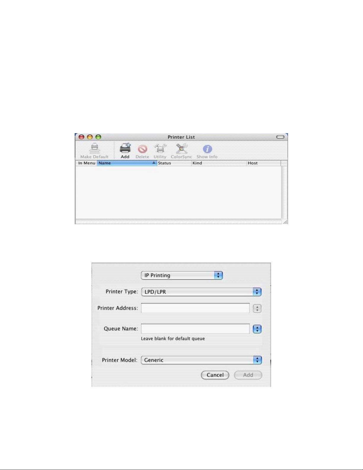
Step 2 – Add Printer
After a few seconds the wi
ndow shown below will appear.
Select Add and the wind
ow shown below will be displayed.
Step 3 – Select printer ty
pe and driver
Select IP Printing
Enter the IP address of the Printer Server in the Printer Address field. This is normally 192.168.2.1 unless
you have changed it to something else.
64
Page 65

The Queue should be entered as LP for a DB25 (parallel) printer or LPUSB for a USB printer
Then select the prin ter that is attached to the printer server from the list.
Now press Add to create the new printer.
After pressing Add the Printer List screen will be displayed and should include the new printer.
Step 4 – Test the printer
he new printer should be tested by trying to print a page from the computer. T
65
Page 66

9 | Troubleshooting
. Verifying your connection to the router A
If you are unable to access t
connected or configured.
To determine your TCP/IP configuration status please follow the steps below:
. Click Start then choose Run.
1
2. Type cmd or command
. In the DOS window, type ipconfig and verify the information that is displayed.
3
4. If your computer is set up for DHCP, then your TCP/IP co
information displayed:
•
•
• e next
section.
IP Address: 192.168.2.x (x is number between 100 and 199 by default.)
Subnet: 255.255.255.0
Gateway: 192.168.2.1 If you have an IP address that starts with 169.254.xxx.xxx then see th
If you have another IP address configured, then see section C.
B. I am getting an IP Address that starts with 169.254.xxx.xxx
If you are g uter.
etting this IP Address, then you need to check that you are properly connected to the Ro
he Router’s web-based administration pages, then you may not be properly
to open a DOS prompt.
nfiguration should be similar to the
Confirm not,
please try a
If you ha d type
ip
If you are still unable to get an IP Address from the Router, r
efer to your adapter manual for information on how to do thr
that you have a good link light on the Router for the port this computer is connected to. If
nother cable.
ve a good link light, please open up a DOS window as described in the previous section an
config/renew.
einstall your network adapter. Please
is.
C. My computer’s IP Address is incorrect
If you have anot ion. Once
you have confir ow.
1. Open a DOS
2. Type ipconfi
3. Then type ipco
her IP address listed then the PC may not be configured for a DHCP connect
med your computer is configured for DHCP, then please follow the steps bel
window as described above.
g/release.
nfig/renew.
D. The 10/100 LED does not light after a connection is made.
1. Check that th
2. Be sure the
3. Verify that of any
cable does n
4. Check the ne
5. The 10BASE
E. I can’t get an Internet
If you are havi y, you can
expose the PC to seful when an
plication requires too many ports or when you are not sure which ports to use. See section 7.8.6 to
ap
ccessfully configure this option
su
e host computer and the Router are both powered on.
network cable is connected to both devices.
Category 5 cable is used if you are operating at 100 Mbps, and that the length
ot exceed 100 m (328 ft).
twork card connections.
-T/100BASE-TX port, network card, or cable may be defective.
game, server, or application to work.
ng an issue getting any Internet server, application or game to function properl
the Internet using the DeMilitarized Zone (DMZ) function. This option is u
66
Page 67

F. I am having problems establishing a PPPoE xDSL WAN connection
Some ISP’s require you to enter the domain name in addition to your username and password. For
instance, for SBC Global, enter username@sbcglobal.net. For Ameritech users
username@ameritech.net. BellSouth users may need to enter username@
bscribers enter username@mindspring.com. Lastly, Earthlink subscribers should enter either
su
username@earthlink.net or ELN/username@earthlink.net.
, enter
bellsouth.net and Mindspring
G. Can I use this router with AOL DSL?
This is true in most scenarios. Please verify with AOL that your particular connection type is PPPoE. If
yes, then the SMC Broadband Router should work with your WAN connection. Follow the normal
procedures as described in Section 7.3 of this manual, but while doing so, set the MTU value to 1400.
AOL DSL does not allow for anything higher than 1400.
H. I forgot my password and can no longer log into the router
You should restore your router to factory defaults via its hardware reset button. Locate the reset button (to
the right of the power input). While the device is powered on, use a paper clip to depress this button for
about 5-7 seconds and then release. Now you have completed the reset to factory defaults.
I. Upgrading the firmware
New firmware revisions will be made available as necessary when new product features or functionality is
released. You should check http://www.smc.com on a periodic basis for these updates. If a new version is
available, check the release notes to be sure of what has been changed/added and then you can decide if
you wish to complete the upgrade. Then download and unzip the firmware file. Log into the web-based
administration of the SMC Router, click TOOLS, then click FIRMWARE UPGRADE and browse to the
new firmware file. Then click the “BEGIN UPGRADE” button to upload the firmware to he SMC Router.
Once this is completed, be sure to reset the router to factory defaults and reconfigure you WAN
connection before continuing to use it.
t
r
67
Page 68

10 | Terminology
10BaseT - Physical Layer Specification for Twisted-Pair Ethernet using Unshielded Twisted Pair wire at
0Mbps. This is the most popular type of LAN cable used today because it is very cheap and easy to
1
install. It uses RJ-45 connectors and has a cable len
STP (Shielded Twisted Pair) which is more expensive and UTP (Unshielded Twisted Pair), the most
popular cable. These cables
Category 3, 4 and 5. CAT 3 TP (Twisted Pair) cable has a network data transfer rate of up to 10Mbps.
CAT 4 TP cable has a network data transfer rate of up to 16Mbps. CAT 5 TP ca
transfer rate of up to 100Mbps.
Access Point - A device that is able to receive wireless signals and transmit them to the wired
Ad Hoc - An ad hoc wireless LAN is a group of computers, each with LAN adapters, connected as an
independent wireless LAN.
Adapter - A device used to connect end-user nodes to the network; each contains an interface to a specific
Auto-Negotiation - A signaling method that allows each node to define its operational mode (e.g., 10/100
Mbps and half/full duplex) and to detect the operational mode of the adjacent node.
Backbone - The core infrastructure of a network. The portion of the network that transports information
from one central location to another central location where it is unloaded onto a local system.
come in 5 different categories. However, only 3 are normally used in LANs,
gth span of up to 100 meters. There are two versions,
ble has a network data
network, and vice versa - thereby creating a connection between the wireless and wired networks.
etc. type of computer or system bus, e.g. EISA, ISA, PCI, PCMCIA, CardBus,
Base Station - In mobile telecommunications, a base station is the central radio transmitter/receiver that
maintains communications with the mobile radiotelephone sets within its range. In cellular and perso
communications applications, each cell or micro-cell has its own base station; each base station in t
interconnected with other cells' bases.
Bitmap – A Windows and OS/2 bitmapped graphics file format. Bitmap files provide formats for 2, 16,
256, or 16 million colors. It uses the extension .BMP.
BSS - BSS stands for "Basic Service Set". It is an Access Point and all the LAN PCs that are
associated with it.
CHAP - When authenticating using Challenge Handshake Authentication
of the password, rather than the password itself is what is sent by the c
te client useRouter sends the remote client a challenge string. The remo
password, and creates a Message Digest-5 (MD5) hash which is then forwarded to the server. The se
ompares the result with the hash sent by the client. If they mcomputes the same hash calculation and c
the remote client is considered an authentic
SMA/CA
C - Carrier Sense Multiple Access with Collision Avoidance
DES - Data Encryption Standard. A cryptographic encryption algorithm that is part of many
standards.
DHCP - Dynamic Host Configuration Protocol. This protocol automatically configures the TCP/IP
settings of every computer on your home network.
user.
Protocol (CHAP), the knowledge
lie
nt. With CHAP, the Broadband
s the challenge string and the
nal
urn is
rver
atch,
68
Page 69

DMZ - Allows a networked computer to be fully exposed to the Internet. This function is used when the
. special application sensing tunnel feature is insufficient to allow an application to function correctly
DNS - DNS stands for Domain Name System, which allows Internet host computers to have a domain
name (such as www.smc.com) and one or more IP addresses (such as 192.34.45.8). A DNS serv
database of host computers and their respective domain name
name is requested (as in typing " www.smc.com" into your Internet browser), the user is sent to the proper
omputers on your home network is the location of the IP address. The DNS server address used by the c
DNS server your ISP has assigned.
DSL - DSL stands for Digital Subscriber Line. A DSL modem uses your existing phone lines to
transmit data at high speeds.
Ethernet - A standard for computer networks. Ethernet networks are connected by special cables and hubs,
and move data around at up to 10 million bits per second (Mbps).
ESS - ESS (ESS-ID, SSID) stands for "Extended Service Set". More than one BSS is configured to
become an Extended Service Set. LAN mobile users can roam between different BSSs in an ESS (ESSID, SSID).
Fast Ethernet NIC - Network interface card that is in compliance with the IEEE 802.3u standard. This
card functions at the media access control (MAC) layer, using carrier sense multiple access with collision
detection (CSMA/CD).
s and IP addresses, so that when a domain
er keeps a
Fixed IP – (see Static IP)
Full-Duplex - Transmitting and receiving data simultaneously. In pure digital networks, this is
achieved with two pairs of wires. In analog networks, or digital networks using carriers, it is achieved
by dividing the bandwidth of the line into two frequencies, one for sending, one for receiving.
ubH - Central connection device for shared media in a star topology. It may add nothing to the
ansmission (passive hub) or may contain electronics that regenerate signals to boost strength as well as
tr
onitor activity (active/intelligent hub). Hubs may be added to bus topologies; for example, a hub can
m
rn an Ethernet network into a star topology to improve troubleshooting.
tu
3
ID – The data fields in an MP3 that hold the artist name, track titles, album titles, genre, etc are known as
3 tags.
ID
Address
IP - IP stands for Internet Protocol. An IP address consists of a series of four numbers
parated by periods, that identifies an single, unique Internet computer host. Example: 192.34.45.8.
se
Security
IP - Provides IP network-layer encryption. IPSec can support large encryption networks (such as
e Internet) by using digital certificates for device authentication.
th
AKMP
IS - Internet Security Association and Key Manangement Protocol. The basis for IKE.
P - Internet Service Provider. An ISP is a business that provides connectivity to the Internet for
IS
viduals and other businesses or organizations.
indi
PEG
J – Joint Photographic Experts Group. JPEG is a standard for compressing still images and it
rovides compression with ratios up to 100:1. File extensions are .JPG or .JPEG.
p
69
Page 70

LAN - A communications network that serves users within a confined geographical area. It is made up of
servers, workstations, a network operating system and a communications link. Servers are high-speed
machines that hold programs and data shared by network users. The workstations (clients) are the users'
personal computers, which perform stand-alone processing and access the network servers as required.
Diskless and floppy-only workstations are sometimes used, which retrieve all software and data from the
server. Increasingly, "thin client" network computers (NCs) and Windows terminals are also used. A
printer can be attached locally to a workstation or to a server and be shared by network users. Small LANs
can allow certain workstations to function as a server, allowing users access to data on another user's
machine. These peer-to-peer networks are often simpler to install and manage, but dedicated se
provide better performance and can handle higher transaction volume. Multiple servers are used in l
networks.
rvers
arge
The message transfer is mana
transmission of data is performed by the access method (Ethernet, Token Ring, etc.), which is
implemented in the network adapters that are plugged into the machines. The actual communications
path is the cable (twisted pair, coax, optical fiber) that interconnects each networ
MAC Address - MAC (Media Access Control) A MAC address is the hardware address of a device
connected to a network.
MDI / MDI-X - Medium Dependent Interface - Also called an "uplink port," it is a port on a network
hub or switch used to connect to other hubs or switches without requiring a crossover cable. The MDI
port does not cross the transmit and receive lines, which is done by the regular ports (MDI-X ports) that
connect to end stations. The MDI port connects to the MDI-X port on the other device. There are
typically one or two ports on a device that can be toggled between MDI (not crossed) and MDI-X
(crossed).
Medium Dependent Interface – X (crossed) - A port on a network hub or switch that crosses the transmit
lines coming in to the receive lines going out.
MP3 – MPEG Audio Layer 3. This is an audio compression technology that is included in the MPEG-1
MPEG – Moving Pictures Experts Group. MPEG is a standard for compressing video. MPEG-1 can
provide resolution of 352x240 at 30 frames/second (fps) with 24-bit color and CD-quality sound. MPEG-2
can provide resolution of 704x480. MPEG uses the same intraframe coding as JPEG for individual frames
but also uses interframe coding which can help to further compress the video data, thereby reducing the
overall size of the video.
ged by a transport protocol such as TCP/IP and NetBEUI. The physical
k adapter.
of 12. and -2 specifications. MP3 encoding can allow you to compress CD-quality sound by a factor
,
NAT – (Network Address Translation) This process allows all of the computers on your home network to
use one IP address. The NAT capability of the Barricade, allows you to access the Internet from any
computer on your home network without having to purchase more IP add
Address Translation can be used to give multiple users access to the Internet with a single user account, or
to map the local address for an IP server (such as Web or FTP) to a public address. This secur
network from direct attack by hackers, and provides more flexible management by allowing y
internal IP addresses without affecting outside access to your network. NAT must be enabled to prov
multi-user access to the Internet or to use the Virtual Server function.
resses from your ISP. Network
es your
ou to change
ide
70
Page 71

Packet Binary Convulational Code (tm) (PBCC) - A modulation technique developed by Texas
Instruments Inc. (TI) that offers data rates of up to 22Mbit/s and is fully backward compatible with
existing 802.11b wireless networks.
PAP - This is a simple authentication protocol where the username and password data are both handled
in a cleartext or unencrypted format. We do not recommend using PAP because your passwords are
easily readable from the Point-to-Point Protocol (PPP) packets exchanged during the authentication
process.
PCI - Peripheral Component Interconnect - Local bus for PCs from Intel that provides a high-spe
path between the CPU and up t
supports 32-bit and 64-bit data paths, and bus mastering.
PPPoE - Point-to-Point Protocol over Ethernet. Point-to-Point Protocol is a method of secure data
transmission originally created for dial-up connections. PPPoE is for Ethernet connections.
PPTP - PPTP stands for Point-to-Point Tunneling Protocol. It provides a means for tunneling IP traffic i
Layer 2. For n instance, it allows you to establish a connection to a corporate network and share files or other
data as if your machine were actually on that local network.
Roaming - A function that allows your to move through a particular domain without losing
network connectivity.
SNMP - Format used for network management data. Data is passed between SNMP agents (processes that
monitor activity in hubs, switches, etc.) and the workstation used to oversee the network. SNMP uses
Management Information Bases (MIBs), which are databases that define what information is ob
from a networked device and what can be controlled (turned off, on, etc.).
Static IP
subnet mask and the gateway address provided by your service provider.
SPI - Stateful Packet Inspection ensures that the data coming into your network was requested by an en
node computer on your LAN. The Barricade examines the incoming data and d compares it to a database of
trusted information. As traffic leaves the network it is defined by certain characteristics. Incoming
information is then compared to these sets of characteristics. If the incoming data matches the predefined
set of chara
- If your Service Provider has assigned a fixed IP address; enter the assigned IP address,
cteristics the incoming traffic is allowed. If no match is found the incoming traffic is discarded.
o 10 peripherals (video, disk, network, etc.). The PCI bus runs at 33MHz,
ed data
tainable
Subnet Mask - A subnet mask, which may be a part of the TCP/IP information provided by you
a set of four numbers configured like an IP address. It is used to create IP address numbers used only
within a particular network (as opposed to valid IP address numbers recognized by the Internet.
TCP/IP - Transmission Control Protocol/Internet Protocol. This is the standard protocol for data
transmission over the Internet.
TCP - Transmission Control Protocol - TCP and UDP (User Datagram Protocol) are the two tran
protocols in TCP/IP. TCP ensures that a message is sent accurately and in its entirety. However, fo
time voice and video, there is really no time or reason to correct e
UDP - User Datagram Protocol - A protocol within the TCP/IP protocol suite that is used in place o
when a reliable delivery is not required. For example, UDP is used for real-time au
where lost packets are simply ignored, because there is no time to retransmit. If UDP is used and a reliable
elivery is required, packet sequence checking and error notification must be written into the applications. d
rrors, and UDP is used instead.
dio and video traffic
r ISP, is
sport
r real-
f TCP
71
Page 72

11 | Technical Specifications
Standards:
IEEE 802.3 10Base-T Ethernet IEEE 802.3u 100Base-TX Fast Ethernet
Hardware / Ports:
LAN Port 4x RJ45, 10/100 Mbps with Auto-MDI/MDIX (BR14UP)
WAN Port 1x RJ45, 10/100 Mbps with Auto-MDI/MDIX
USB Port 1 x USB Jack (type A), USB 1.1 Compliant
Printer Port 1 x DB25 (female)
Input Power DC 5V2A
LEDs:
Power 1x Green LED for Power
WAN 1x Amber LED for 10Mbps link / Green LED for 100Mpbs link
Blinking LED when data is transmitted
LAN (4 port) 4x Amber LED for 10Mbps connection
4x Green LED for 100Mbps connection
Blinking LED when data is transmitted
Key management: IKE, Manual Aggressive/Main mode for Remote gateway FQDN support Dynam
support Encryption algorithm: DES, 3DES, AES Authentication algorithm: MD5, SHA-1 PFS supp
Keying Mode:
Routing:
Static Route Dynamic Route (RIP1/2)
Power:
Input Power 5V 2A
AC power consumption →11Watts max (AC 0.1A/110Volt)
Pre-Shared Key Enabled NetBIOS Broadcast
Operating Temperature:
0~40oC Humidity: 10%~90% non-condensing
ic
ort
Storage Temperature:
-20~70oC, Humidity: 0~95% non-condensing
Dimensions
235mm(L)x135mm(W)x 38 mm(H) (9 .25x5.31x1.49 in)
Weight
350g
Compliances:
FCC CE VCCI UL
72
Page 73

12 | COMPLIANCES FCC Interference Statement
This equipment has been tested and found to comply with the limits for a Class B digital device pursuant to Par
the FCC Rules. These limits are designed t
environment. This equipment can generate, use and radiate radio frequency energy and, if not installed and used in
accordance with the instructions in this manual, may cause harmful interference to radio communications. Operation of
this equipment in a residential area is likely to cause interference, in which case the user, at his own expense, wi
required to take whatever measures are necessary to correct the interference.
o provide reasonable protection against radio interference in a commercial
Industry Canada – Class B
t 15 of
ll be
This digital apparatus does not exceed the Class B limits for radio noise emissions from digital apparatus as set out in
the interference-causing equipment standard entitled “Digital Apparatus” ICES-003 of the Department of
Communications.
Cet appareil numérique respecte les limites de bruits radioélectriques applicables aux appareils numériques de
prescrites dans la norme sur le matériel brouilleur: « Appareils Numériques » NMB-003 édictée par le ministèr
Communications.
Classe B
e des
EC Conformance Declaration – Class B
SMC contact for these products in Europe is:
SMC Networks Europe,
Edificio Conata II,
Calle Fructuós Gelabert 6-8, 2o, 4a,
08970 - Sant Joan Despí,
Barcelona, Spain.
This product complies with the requirements of theCouncil Directive 89/336/EEC
on the Approximation of the laws of the Member States relating to Electromagnetic
Compatibility and 73/23/EEC for electrical equipment used within certain voltage
limits and the Amendment Directive 93/68/ EEC. For the evaluation of the
compliance with these Directives, the following standards were applied:
Emission:
EN 5022: 1998+A1:2000
EN 61000-3-2: 2000, EN 61000-3-3: 1995+A1:2000
Immunity
EN 55024:1998+A1:2001,
EN 61000-4-2, 61000-4-3, 61000-4-4, 61000-4-5
EN 61000-4-6, 61000-4-11
Safety Test:
UL 1950
EN60950
CSA 22.2 No. 950
73
Page 74

Safety Compliance
Wichtige Sicherheitshinweise (Germany)
1.Bitte lesen Sie diese Hinweise sorgf
2.Heben Sie diese Anleitung für den späteren Gebrauch auf.
3.Vor jede
Aerosolreiniger. Ambesten eignet sich ein angefeuchtetes Tuch zur Reinigu
4.Die Netzanschlußsteckdose soll nahe dem Gerät angebracht und leicht zugä
5.Das Gerät ist vor Feu
6.Bei der Aufstellu
hervorrufen.
7.Die Be
diese Ö
8.Beacht nschluß an das Stromnetz die Anschlußwerte.
9.Verlegen zanschlußleitung so, da
abgestell
10. Alle Hin ungen, d
11. W
F
12. D
13. Öffnen Sie niemals ktrischen Sicherheit nur von authorisiertem
das Gerät. Das Gerät darf aus Gründen der ele
Servicepersonal geöffnet werden.
. 14. Wenn folgende Situ
Servicestell
a. Netzkabel oder Ne
b.Flüssigkeit ist in da
s Gerät eingedrungen.
c.Das Gerät war Feuchtigkeit ausgesetzt.
d.Wenn das Gerät nicht der Bedienungsanleitung entsprechend funktioniert oder Sie mit Hilfe dieser Anleitu
keine Verbesserung erzielen.
. e.Das Gerät ist gefallen und/oder das Gehäuse ist beschädigt.
f.Wenn das Gerät deutliche Anzeichen eines Defektes aufweis
15. Stell
Stromversorgung sollten die Werte von A
Strom von 1A nicht unterschreiten. Der
70dB(A) oder weniger.
m Reinigen ist das Gerät vom Stromnetz zu trennen. Verwenden Sie keine Flüssig- oder
chtigkeit zu schützen.
ng des Gerätes ist auf sicheren Stand zu achten. Ein Kippen oder Fallen könnte Beschädigungen
lüftungsöffnu ützt. Sorgen Sie dafür, daß
ffnungen nich
en Sie beim A
Sie die Net ß niemand darüber fallen kann. Es sollte auch nichts auf der Leitung
t werden.
weise und Warn ie sich am Gerät befinden, sind zu beachten.
ird das Gerät über inen längeren Zeitraum nicht benutzt, sollten Sie es vom Stromnetz trennen. Somit wird im
lle einer Überspan ieden.
a
urch die Lüftungsö . Dies könnte
inen Brand bzw. el
en Sie sicher, daß die Stromversorgung dieses Gerätes nach der EN60950 geprüft ist. Ausgangswerte der
ngen dienen der Luftzirkulation, die das Gerät vor Üb
t abgedeckt werden.
e
nung eine Beschädigung verm
ffnungen dürfen niemals Gegenstände oder Flüssigkeiten in das Gerät gelangen
ektrischen Schlag auslösen. e
ationen auftreten ist das Gerät vom Stromnetz
e zu übe
rprüfen:
tzstecker sind beschädigt.
ältig durch.
ng.
nglich sein.
erhitzung sch
zu trennen und von einer qualifizierten
t.
C 7,5-8V, 50-60Hz nicht über- oder unterschreiten sowie den minimalen
arbeitsplatzbezogene Schalldruckpegel nach DIN 45 635 Teil 1000 beträgt
ng
74
Page 75

13 | LEGAL INFORMATION AND CONTACTS
SMC's Limited Warranty Statemen
SMC Networks Europe ("SMC") warrants its products to be free from defects in workmanship and materials, under
normal use and service, for the applicable warranty term. All SMC products carry a standard 2 year limited warranty
from the date of purchase from SMC or its Authorized Reseller. SMC may, at its own discretion, repair or replace an
product not operating as warranted with a similar or functionally equivalent product, during the applicable warranty
term. SMC will endeavor to repair or replace any product returned under warranty within 30 days of receipt of the
product. As new technologies emerge, older technologies become obsolete and
older product in its product line with one that incorporates these newer technologies.
The standard limited warranty can
within 30 days of purchase from SMC or its Authorized Reseller. Registration can be accomplished via the enclosed
product registration card or online via the SMC web site. Failure to register will not affect the standard limited
warranty. The Limited Lifetime warranty covers a product during the Life of that Product, which is defined as a period
of 5 years from the date of purchase of the product from SMC or its authorized reseller.
All products that are replaced become the property of SMC. Replacement products may be either new or reconditioned.
Any replaced or repaired product carries, either a 30-day limited warranty or the remainder of the initial warranty,
whichever is longer. SMC is not responsible for any custom software or firmware, configuration information, or
memory data of Customer contained in
warranty. Products returned to SMC should have any customer-installed accessory or add-on components, such as
expansion modules, removed prior to returning th
they are returned with the product.
Customers must contact SMC for a Return Ma
Proof of purchase may be required. Any produ
(RMA) number clearly m
Customers are responsible for all shipping ch
shipping charges from SMC to custom
WARRANTIES EXCLUS
CUSTOMER'S SOLE REMED
QUESTION, AT S
ND ARE IN LIEU OF ALL OTHER WARRANTIES OR CONDITIONS, EXPRESSED OR IMPLIED,
A
EITHER IN FACT OR BY OPERATION OF LAW, STATUTORY OR OTHERWISE,
WARRANTIES OR CONDITIONS OF MERCHANTABILITY AND FITNESS FO
PURPOSE. SMC NEITHER ASSUMES NOR AUTHORIZES ANY OTHER PERS
ANY OTHER LIABILITY IN CONNECTION WITH THE SALE, INSTALLATIO
USE OF ITS PRODUCTS. SMC SHALL NOT BE LIABLE UNDER THIS
AND EXAMINATION DISCLOSE THE ALLEGED DEFECT IN THE P
AS CAUSED BY CUSTOMER'S OR ANY THIRD PERSON'S MISUSE, NEGLECT, IMPROPER
W
INSTALLATION OR TESTING, UNAUTHORIZED ATTEMPTS TO REPAIR, OR ANY OTHER CAUSE
BEYOND THE RANGE OF THE INTENDED USE, OR BY ACCIDENT, FIRE, LIGHTNING, OR OTHER
H
AZARD.
LIMITATION OF LIABILITY: IN NO EVENT, WHETHER BASED IN CONTRACT OR TORT (INCLUDING
NEGLIGENCE), SHALL SMC BE LIABLE FOR INCIDENTAL, CONSEQUENTIAL, INDIRECT, SPECIAL, OR
PUNITIVE DA Y KIND, OR FOR LOSS OF REVENUE, LOSS OF BUSINESS, OR OTHER
F NNECTION WITH THE SALE, INSTALLATION,
INANCIAL LOSS ARISING OUT OF OR IN CO
M RE, OR INTERRUPTION OF ITS PRODUCTS, EVEN IF SMC
AINTENANCE, USE, PERFORMANCE, FAILU
OR ITS AUTHORIZED RESELLER HAS BEEN ADVISED OF THE POSSIBILITY OF SUCH DAMAGES.
SOME COUNTRIES DO NOT ALLOW THE EXCLUSION OF IMPLIED WARRANTIES OR THE LIMITATION
OF INCIDENTAL OR CONSEQUENTIAL DAMAGES FOR CONSUMER PRODUCTS, SO THE ABOVE
LIMITATIONS AND EXCLUSIONS MAY NOT APPLY TO YOU. THIS WARRANTY GIVES YOU SPECIFIC
LEGAL RIGHTS, WHICH MAY VARY FROM COUNTRY TO COUNTRY. NOTHING IN THIS WARRANTY
SHALL BE TAKEN TO AFFECT YOUR STATUTORY RIGHTS.
* time warranty, internal and external power supplies, fans, and cables are covered by a
Under the limited life
standard one-year warranty from date of purchase.
MAGES OF AN
arked on the outside of the package will be returned to customer at customer's expense.
IVE: IF A SMC PRODUCT DOES NOT OPERATE AS WARRANTED ABOVE,
Y SHALL BE REPAIR OR REPLACEMENT OF THE PRODUCT IN
MC'S OPTION. THE FOREGOING WARRANTIES AND REMEDIES ARE EXCLUSIVE
t
y
SMC will, at its discretion, replace an
be upgraded to a 5 year Limited Lifetime * warranty by registering new products
, stored on, or integrated with any products returned to SMC pursuant to any
e product for replacement. SMC is not responsible for these items if
terial Authorization number prior to returning any product to SMC.
ct returned to SMC without a valid Return Material Authorization
arges from their facility to SMC. SMC is responsible for return
er.
INCLUDING
R A PARTICULAR
ON TO ASSUME FOR IT
N, MAINTENANCE OR
WARRANTY IF ITS TESTING
RODUCT DOES NOT EXIST OR
75
Page 76

Full Installation Manual
F nstallation CD-Rom. Manuals in other languages than those
ull installation manuals are provided on the I
i uded on the CD-Rom are provided on www.smc.com (section support).
ncl
Firmware and Drivers
For latest driver, technical information and bug-fixes please
visit www.smc.com
(section support).
Contact SMC
Contact details for your relevant countries are available on www.smc.com.
Statement of Conditions
In line with our continued efforts to improve internal design, operational function, and/or reliability, SMC
reserves the right to make changes to the product(s) described in this document without notice. SMC does
not assume any liability that may occur due to the use or application of the pro
order to obtain the most accurate knowledge of installation, bug-fixes and other product related information
we advise to visit the relevant product support page at www before you start installing the
equipment. All information is subject to change without notice.
.smc.com
duct(s) described herein. In
Limitation of Liability
In no event, whether based in contract or tort (including negligence), shall SMC be liable for incidental
consequential, indirect, special or punitive damage
or other financial loss arising out of or in conne
performance, failure or interruption of its prod
advised of the possibility of such damages.
s of any kind, or for loss of revenue, loss of business
ction with the sale, installation, maintenance, use,
ucts, even if SMC or its authorized reseller has been
,
Copyright
Information furnished by SMC Networks, Inc. (SMC) is believed to be accurate and reliable. However,
no
responsibility is assumed by SMC for its use, nor for any infringements of patents or other rights of
thi
rd parties which may result from its use. No license is granted by implication or otherwise under any
pat C. SMC reserves the right to change specifications at any time without
ent or patent rights of SM
otice.
n
rademarks
T
MC is a registered trademark and EZ Connect is a trademark of SMC Networks, Inc. Other product and
S
ompany names are trademarks or registered trademarks of their respective holders.
c
76
Page 77

FOR TECHNICAL SUPPORT, CALL:
From U.S.A. and Canada (24 hours a day, 7 days a week)
(800) SMC-4-YOU; Phn: (949) 679-8000; Fax: (949) 679-1481
From Europe : Contact details can be found on www.smc.com
INTERNET
E-mail address:
techsupport@smc.com
Driver updates:
http://www.smc.com/index.cfm?action=tech_support_drivers_downloads
World Wide Web:
http://www.smc.com/
For Literature or Advertising Response, Call:
U.S.A. and Canada: (800) SMC-4-YOU Fax (949) 679-1481
Spain: 34-91-352-00-40 Fax 34-93-477-3774
UK: 44 (0) 871 277 98 02 Fax 44 (0) 1234 831 413
France: 33 (0) 1 55 64 04 55 Fax 33 (0) 1 45 34 68 58
Italy: 39 02 739 12 68 Fax 39 02 739 14 17
Benelux: 31 (0) 654 776 790 Fax 31 (0) 172 242 393
Central Europe: 49 (0) 89 92861-0 Fax 49 (0) 89 92861-230
Nordics and Baltics: 45 (0) 566 622 83 Fax 45 (0) 566 622 86
Eastern Europe: 420 266 794 421 Fax 420 266 794 423
Sub-Saharan Africa: 27 012 661 02 32 Fax 34 93 477 3774
North West Africa: 34 93 477 4920 Fax 34 93 477 3774
CIS: 34 93 477 4920 Fax 34 93 477 3774
PRC: 86-10-6235-4958 Fax 86-10-6235-4962
Taiwan: 886-2-87978006 Fax 886-2-87976288
Asia Pacific: (65) 238 6556 Fax (65) 238 6466
Korea: 82-2-553-0860 Fax 82-2-553-7202
Japan: 81-45-224-2332 Fax 81-45-224-2331
Australia:
61-2-8875-7887 Fax 61-2-8875-7777
India: 91-22-8204437 Fax 91-22-8204443
If you are looking for further contact information, please visit www.smc.com.
Model Number: SMCBR14UP
38 Tesla
Irvine, CA 92618
Phone: (949) 679-8000
 Loading...