

Page 1

INSTALLATION GUIDE
Installationsanleitung
SMC8124PL2
TigerSwitch 10/100/1000
24-Port Managed Switch with PoE
TM
Page 2

Page 3

TigerSwitch 10/100/1000
Installation Guide
From SMC’s Tiger line of feature-rich workgroup LAN solutions
20 Mason
Irvine, CA 92618
Phone: (949) 679-8000
Pub. # 150200061500A
May 2007
E052007-DT-R01
Page 4

Information furnished by SMC Networks, Inc. (SMC) is believed to be accurate and
reliable. However, no responsibility is assumed by SMC for its use, nor for any
infringements of patents or other rights of third parties which may result from its use. No
license is granted by implication or otherwise under any patent or patent rights of SMC.
SMC reserves the right to change specifications at any time without notice.
Copyright © 2007 by
SMC Networks, Inc.
20 Mason
Irvine, CA 92618
All rights reserved. Printed in Taiwan
Trademarks:
SMC is a registered trademark; and EZ Switch, TigerStack and TigerSwitch are
trademarks of SMC Networks, Inc. Other product and company names are trademarks or
registered trademarks of their respective holders.
Page 5

Limited Warranty
Limited Warranty Statement: SMC Networks, Inc. (“SMC”) warrants its products to be
free from defects in workmanship and materials, under normal use and service, for the
applicable warranty term. All SMC products carry a standard 90-day limited warranty from
the date of purchase from SMC or its Authorized Reseller. SMC may , at its own discretion,
repair or replace any product not operating as warranted with a similar or functionally
equivalent product, during the applicable warranty term. SMC will endeavor to repair or
replace any product returned under warranty within 30 days of receipt of the product.
The standard limited warranty can be upgraded to a Limited Lifetime* warranty by
registering new products within 30 days of purchase from SMC or its Authorized Reseller.
Registration can be accomplished via the enclosed product registration card or online via
the SMC Web site. Failure to register will not affect the standard limited warranty. The
Limited Lifetime warranty covers a product during the Life of that Product, which is
defined as the period of time during which the product is an “Active” SMC product. A
product is considered to be “Active” while it is listed on the current SMC price list. As new
technologies emerge, older technologies become obsolete and SMC will, at its discretion,
replace an older product in its product line with one that incorporates these newer
technologies. At that point, the obsolete product is discontinued and is no longer an
“Active” SMC product. A list of discontinued products with their respective dates of
discontinuance can be found at:
http://www.smc.com/index.cfm?action=customer_service_warranty.
All products that are replaced become the property of SMC. Replacement products may
be either new or reconditioned. Any replaced or repaired product carries either a 30-day
limited warranty or the remainder of the initial warranty, whichever is longer. SMC is not
responsible for any custom software or firmware, configuration information, or memory
data of Customer contained in, stored on, or integrated with any products returned to
SMC pursuant to any warranty. Products returned to SMC should have any
customer-installed accessory or add-on components, such as expansion modules,
removed prior to returning the product for replacement. SMC is not responsible for these
items if they are returned with the product.
Customers must contact SMC for a Return Material Authorization number prior to
returning any product to SMC. Proof of purchase may be required. Any product returned
to SMC without a valid Return Material Authorization (RMA) number clearly marked on
the outside of the package will be returned to customer at customer’s expense. For
warranty claims within North America, please call our toll-free customer support number
at (800) 762-4968. Customers are responsible for all shipping charges from their facility to
SMC. SMC is responsible for return shipping charges from SMC to customer.
WARRANTIES EXCLUSIVE: IF AN SMC PRODUCT DOES NO T OPERATE AS
WARRANTED ABOVE, CUSTOMER’S SOLE REMEDY SHALL BE REPAIR OR
REPLACEMENT OF THE PRODUCT IN QUESTION, AT SMC’S OPTION. THE
FOREGOING WARRANTIES AND REMEDIES ARE EXCLUSIVE AND ARE IN LIEU OF
ALL OTHER WARRANTIES OR CON DITIONS, EXPRESS OR IMPLIED, EITH ER I N
FACT OR BY OPERATION OF LAW, STATUTORY OR OTHERWISE, INCLUDING
WARRANTIES OR CONDITIONS OF MERCHANTABILITY AND FITNESS FOR A
PAR TICULAR PURPOSE. SMC NEITHER ASSUMES NOR AUTHORIZES ANY OT HER
PERSON TO ASSUME FOR IT ANY OTHER LIABILITY IN CONNECTION WITH THE
SALE, INSTALLATION, MAINTENANCE OR USE OF ITS PRODUCTS. SMC SHALL
v
Page 6

NOT BE LIABLE UNDER THIS WARRANTY IF ITS TESTING AND EXAMINATION
DISCLOSE THE ALLEGED DEFECT IN THE PRODUCT DOES NOT EXIST OR WAS
CAUSED BY CUSTOMER’S OR ANY THIRD PERSON’S MISUSE, NEGLECT,
IMPROPER INSTALLATION OR TESTING, UNAUTHORIZED ATTEMPTS TO REPAIR,
OR ANY OTHER CAUSE BEYOND THE RANGE OF THE INTENDED USE, OR BY
ACCIDENT, FIRE, LIGHTNING, OR OTHER HAZARD.
LIMITATION OF LIABILITY: IN NO EVENT, WHETHER BASED IN CONTRACT OR
TORT (INCLUDING NEGLIGENCE), SHALL SMC BE LIABLE FOR INCIDENTAL,
CONSEQUENTIAL, INDIRECT , S PECIAL, OR PUNITIVE DAMAGES OF ANY KIND, OR
FOR LOSS OF REVENUE, LOSS OF BUSINESS, OR OTHER FINANCIAL LOSS
ARISING OUT OF OR IN CONNECTION WITH THE SALE, I N STALLAT ION,
MAINTENANCE, USE, PERFORMANCE, FAILURE, OR INTERRUPTION OF ITS
PRODUCTS, EVEN IF SMC OR ITS AUTHORIZED RESELLER HAS BEEN ADVISED
OF THE POSSIBILITY OF SUCH DAMAGES.
SOME STATES DO NOT ALLOW THE EXCLUSION OF IMPLIED WARRANTIES OR
THE LIMITATION OF INCIDENTAL OR CONSEQUENTIAL DAMAGES FOR
CONSUMER PROD UCTS, SO THE ABOVE LIMITATIONS AND EXCL USIONS MAY
NOT APPLY T O YOU. THIS WARRANTY GIVES YOU SPECIFIC LEGAL RIGHTS,
WHICH MAY VARY FROM STATE TO STATE. NOTHING IN THIS WARRANTY SHALL
BE TAKEN T O AFFECT YOUR STATUTORY RIGHTS.
* SMC will provide warranty service for one year following discontinuance from the active
SMC price list. Under the limited lifetime warranty, internal and external power supplies,
fans, and cables are covered by a standard one-year warranty from date of purchase.
SMC Networks, Inc.
20 Mason
Irvine, CA 92618
vi
Page 7

Compliances and Safety Warnings
FCC - Class A
This equipment has been tested and found to comply with the limits for a Class A digital
device, pursuant to part 15 of the FCC Rules. These limits are designed to provide
reasonable protection against harmful interference when the equipment is operated in a
commercial environment. This equipment generates, uses, and can radiate radio
frequency energy and, if not installed and used in accordance with the instruction manual,
may cause harmful interference to radio communications. Operation of this equipment in
a residential area is likely to cause harmful interference in which case the user will be
required to correct the interference at his own expense.
You are cautioned that changes or modifications not expressly approved by the party
responsible for compliance could void your authority to operate the equipment.
You may use unshielded twisted-pair (UTP) for RJ-45 connections - Category 3 or better
for 10 Mbps connections, Category 5 or better for 100 Mbps connections, Category 5, 5e,
or 6 for 1000 Mbps connections. For fiber optic connections, you may use 50/125 or 62.5/
125 micron multimode fiber or 9/125 micron single-mode fiber.
Industry Canada - Class A
This digital apparatus does not exceed the Class A limits for radio noise emissions from
digital apparatus as set out in the interference-causing equipment standard entitled
“Digital Apparatus,” ICES-003 of the Department of Communications.
Cet appareil numérique respecte les limites de bruits radioélectriques applicables aux
appareils numériques de Classe A prescrites dans la norme sur le matériel brouilleur:
“Appareils Numériques,” NMB-003 édictée par le ministère des Communications.
Japan VCCI Class A
vii
Page 8

CE Mark Declaration of Conformance for EMI and Safety (EEC)
This information technology equipment complies with the requirements of the Council
Directive 89/336/EEC on the Approximation of the laws of the Member States relating to
Electromagnetic Compatibility and 73/23/EEC for electrical equipment used within certain
voltage limits and the Amendment Directive 93/68/EEC. For the evaluation of the
compliance with these Directives, the following standards were applied:
RFI Emission: Limit class A according to EN 55022:1998
Limit class A for harmonic current emission according to EN 61000-3-2/1995
Limitation of voltage fluctuation and flicker in low-voltage supply system according to
EN 61000-3-3/1995
Immunity: Product family standard according to EN 55024:1998
Electrostatic Discharge according to EN 61000-4-2:1995 (Contact Discharge: ±4 kV,
Air Discharge: ±8 kV)
Radio-frequency electromagnetic field according to EN 61000-4-3:1996 (80 - 1000
MHz with 1 kHz AM 80% Modulation: 3 V/m)
Electrical fast transient/burst according to EN 61000-4-4:1995 (AC/DC power supply:
±1 kV, Data/Signal lines: ±0.5 kV)
Surge immunity test according to EN 61000-4-5:1995
(AC/DC Line to Line: ±1 kV, AC/DC Line to Earth: ±2 kV)
Immunity to conducted disturbances, Induced by radio-frequency fields:
EN 61000-4-6:1996 (0.15 - 80 MHz with
1 kHz AM 80% Modulation: 3 V/m)
Power frequency magnetic field immunity test according to EN 61000-4-8:1993 (1 A/m
at frequency 50 Hz)
Voltage dips, short interruptions and voltage variations immunity test according to
EN 61000-4-11:1994 (>95% Reduction @10 ms, 30% Reduction @500 ms, >95%
Reduction @5000 ms)
LVD: EN 60950-1:2001
Caution: Do not plug a phone jack connector in the RJ-45 port. This may damage this
Attention:Les raccordeurs ne sont pas utilisés pour le système téléphonique!
device.
viii
Page 9

Safety Compliance
Warning: Fiber Optic Port Safety
CLASS I
LASER DEVICE
When using a fiber optic port, never look at the tra nsmit laser while it is
powered on. Also, nev er look d irectly at the f iber T X port and fiber c able
ends when they are powered on.
Avertissment: Ports pour fibres optiques - sécurité sur le plan optique
DISPOSITIF LASER
DE CLASSE I
Ne regardez jamais le laser tant qu'il est sous tension. Ne regardez
jamais directement le port TX (Transmission) à fibres optiques et les
embouts de câbles à fibres optiques tant qu'ils sont sous tension.
Warnhinweis: Faseroptikanschlüsse - Optische Sicherheit
LASERGER
DER KLASSE I
Niemals ein Übertragungslaser betrachten, während dieses
ÄT
eingeschaltet ist. Niemals direkt auf den Faser-TX-Anschluß
und auf die Faserkabelenden schauen, während diese
eingeschaltet sind.
Power Cord Safety
Please read the following safety information carefully before installing this switch:
Warning: Installation and removal of the unit must be carried out by qualified personnel
only.
• The unit must be connected to an earthed (grounded) outlet to comply with international
safety standards.
• Do not connect the unit to an A.C. outlet (power supply) without an earth (ground)
connection.
• The appliance coupler (the connector to the unit and not the wall plug) must have a
configuration for mating with an EN 60320/IEC 320 appliance inlet.
• The socket outlet must be near to the unit and easily accessible. You can only remove
power from the unit by disconnecting the power cord from the outlet.
• This unit operates under SELV (Safety Extra Low Voltage) conditions according to
IEC 60950. The conditions are only maintained if the equipment to which it is connected
also operates under SELV conditions.
France and Peru only
This unit cannot be powered from IT
must be powered by 230 V (2P+T) via an isolation transformer ratio 1:1, with the
secondary connection point labelled Neutral, connected directly to earth (ground).
†
Impédance à la terre
†
supplies. If your supplies are of IT type, this unit
ix
Page 10

Important! Before making connections, make sure you have the correct cord set. Check
it (read the label on the cable) against the following:
Power Cord Set
U.S.A. and Canada The cord set must be UL-approved and CSA certified.
The minimum specifications for the flexible cord are:
- No. 18 AWG - not longer than 2 meters, or 16 AWG.
- Type SV or SJ
- 3-conductor
The cord set must have a rated current capacity of at least 10 A
The attachment plug must be an earth-grounding type with NEMA 5-15P (15 A,
125 V) or NEMA 6-15P (15 A, 250 V) configuration.
Denmark The supply plug must comply with Section 107-2-D1, Standard DK2-1a or
Switzerland The supply plug must comply with SEV/ASE 1011.
U.K. The supply plug must comply with BS1363 (3-pin 13 A) and be fitted with a 5 A
Europe The supply plug must comply with CEE7/7 (“SCHUKO”).
DK2-5a.
fuse which complies with BS1362.
The mains cord must be <HAR> or <BASEC> marked and be of type
HO3VVF3GO.75 (min imu m) .
The mains cord must be <HAR> or <BASEC> marked and be of type
HO3VVF3GO.75 (min imu m) .
IEC-320 receptacle.
Veuillez lire à fond l'information de la sécurité suivante avant
d'installer le Switch:
AVERTISSEMENT: L’installation et la dépose de ce groupe doivent être confiés à un
personnel qualifié.
• Ne branchez pas votre appareil sur une prise secteur (alimentation électrique) lorsqu'il
n'y a pas de connexion de mise à la terre (mise à la masse).
• Vous devez raccorder ce groupe à une sortie mise à la terre (mise à la masse) afin de
respecter les normes internationales de sécurité.
• Le coupleur d’appareil (le connecteur du groupe et non pas la prise murale) doit
respecter une configuration qui permet un branchement sur une entrée d’appareil EN
60320/IEC 320.
• La prise secteur doit se trouver à proximité de l’appareil et son accès doit être facile.
Vous ne pouvez mettre l’appareil hors circuit qu’en débranchant son cordon électrique
au niveau de cette prise.
• L’appareil fonctionne à une tension extrêmement basse de sécurité qui est conforme à
la norme IEC 60950. Ces conditions ne sont maintenues que si l’équipement auquel il
est raccordé fonctionne dans les mêmes conditions.
France et Pérou uniquement:
x
Page 11

Ce groupe ne peut pas être alimenté par un dispositif à impédance à la terre. Si vos
alimentations sont du type impédance à la terre, ce groupe doit être alimenté par une
tension de 230 V (2 P+T) par le biais d’un transformateur d’isolement à rapport 1:1, avec
un point secondaire de connexion portant l’appellation Neutre et avec raccordement
direct à la terre (masse).
Cordon électrique - Il doit être agréé dans le pays d’utilisation
Etats-Unis et Canada: Le cordon doit avoir reçu l’homologation des UL et un certificat de la CSA.
Les spécifications minimales pour un cable flexible sont AWG No. 18, ouAWG
No. 16 pour un cable de longueur inférieure
- type SV ou SJ
- 3 conducteurs
Le cordon doit être en mesure d’acheminer un courant nominal d’au moins 10
A.
La prise femelle de branchement doit être du type à mise à la terre (mise à la
masse) et respecter la configuration NEMA 5-15P (15 A, 125 V) ou NEMA
6-15P (15 A, 250 V).
Danemark: La prise mâle d’alimentation doit respecter la section 107-2 D1 de la norme
Suisse: La prise mâle d’alimentation doit respecter la norme SEV/ASE 1011.
Europe La prise secteur doit être conforme a ux normes CEE 7/7 (“SCHUKO”)
DK2 1a ou DK2 5a.
LE cordon secteur doit porter la mention <HAR> ou <BASEC> et doit être de
type HO3VVF3GO.75 (minimum).
à
2 métres.
Bitte unbedingt vor dem Einbauen des Switches die folgenden
Sicherheitsanweisungen durchlesen:
WARNUNG: Die Installation und der Ausbau des Geräts darf nur durch Fachpersonal
erfolgen.
• Das Gerät sollte nicht an eine ungeerdete Wechselstromsteckdose angeschlossen
werden.
• Das Gerät muß an eine geerdete Steckdose angeschlossen werden, welche die
internationalen Sicherheitsnormen erfüllt.
• Der Gerätestecker (der Anschluß an das Gerät, nicht der Wandsteckdosenstecker) muß
einen gemäß EN 60320/IEC 320 konfigurierten Geräteeingang haben.
• Die Netzsteckdose muß in der Nähe des Geräts und leicht zugänglich sein. Die
Stromversorgung des Geräts kann nur durch Herausziehen des Gerätenetzkabels aus
der Netzsteckdose unterbrochen werden.
• Der Betrieb dieses Geräts erfolgt unter den SELV-Bedingungen
(Sicherheitskleinstspannung) gemäß IEC 60950. Diese Bedingungen sind nur gegeben,
wenn auch die an das Gerät angeschlossenen Geräte unter SELV-Bedingungen
betrieben werden.
xi
Page 12

Stromkabel. Dies muss von dem Land, in dem es benutzt wird geprüft werden:
Schweiz Dieser Stromstecker muß die SEV/ASE 1011Bestimmungen einhalten.
Europe Das Netzkabel muß vom Typ HO3VVF3GO.75 (Mindestanforderung) sein und
die Aufschrift <HAR> oder <BASEC> tragen.
Der Netzstecker muß die Norm CEE 7/7 erfüllen (”SCHUKO”).
Warnings and Cautionary Messages
Warning: This product does not contain any serviceable user parts.
Warning: Installation and removal of the unit must be carried out by qualified
personnel only.
Warning: When connecting this device to a power outlet, connect the field
Warning: This switch uses lasers to transmit signals over fiber optic cable. The
Caution: Wear an anti-static wrist strap or take other suitable measures to
Caution: Do not plug a phone jack connector in the RJ-45 port. This may
Caution: Use only twisted-pair cables with RJ-45 connectors that conform to
ground lead on the tri-pole power plug to a valid earth ground line to
prevent electrical hazards.
lasers are compliant with the requirements of a Class 1 Laser
Product and are inherently eye safe in normal operation. However,
you should never look directly at a transmit port when it is powered
on.
prevent electrostatic discharge when handling this equipment.
damage this device. Les raccordeurs ne sont pas utilisé pour le
système téléphonique!
FCC standards.
Warnings (in German)
Achtung: Dieses Produkt enthält keine Teile, die eine Wartung vom Benutzer
Achtung: Installation und Deinstallation des Gerätes müssen von qualifiziertem
Achtung: Wenn das Gerät an eine Steckdose angesc hlossen wird, muß der
Achtung: Dieses Gerät nutzt Laser zur Signalübertragung über Glasfasern. Die
xii
benötigen.
Servicepersonal durchgeführt werden.
Masseanschluß am dreipoligen Netzstecker mit Schutzerde
verbunden werden, um elektrische Gefahren zu vermeiden.
Laser entsprechen den Anforderungen an eine Lasereinrichtung der
Klasse 1 und sind durch ihre Bauart im normalen Betrieb sicher für die
Augen. Trotzdem sollte niemals direkt in den einen
Übertragungskanal geblickt werden, wenn er eingeschaltet ist.
Page 13

Environmental Statement
The manufacturer of this product endeavours to sustain an environmentally-friendly policy
throughout the entire production process. This is achieved though the following means:
• Adherence to national legisl at ion and regulations on env iron mental production
standards.
• Conservation of operational resources.
• Waste reduction and safe di sposal of all harmful un-recyclable by-produ cts.
• Recycling of all reusable wa st e content.
• Design of products to maximi ze recyclables at the end of t he pr oduct’s life span.
• Continual monitoring of sa fety sta ndards.
End of Product Life Span
This product is manufactured in such a way as to allow for the recovery and disposal of all
included electrical components once the product has reached the end of its life.
Manufacturing Materials
There are no hazardous nor ozone-depleting materials in this product.
Documentation
All printed documentation for this product uses biodegradable paper that originates from
sustained and managed forests. The inks used in the printing process are non-toxic.
Purpose
This guide details the hardware features of this switch, including Its physical and
performance-related characteristics, and how to install the switch.
Audience
This guide is for system administrators with a working knowledge of network
management. You should be familiar with switching and networking concepts.
Zielgruppe Dieser Anleitung ist fuer Systemadministratoren mit Erfahrung im
Netzwerkmangement. Sie sollten mit Switch- und Netzwerkkonzepten vertraut sein.
Related Publications
The following publication gives specific information on how to operate and use the
management functions of this switch:
The SMC8124PL2 Management Guide
Also, as part of both switches firmware, there is an online web-based help that describes
all management related features.
xiii
Page 14

xiv
Page 15

Contents
Chapter 1: About the TigerSwitch 10/100/1000 1-1
Overview 1-1
Switch Architecture 1-1
Power-over-Ethernet Capability 1-2
Network Management Options 1-2
Description of Hardware 1-2
10/100/1000BASE-T Ports 1-2
SFP Slots 1-3
Port and System Status LEDs 1-3
Power Supply Socket 1-4
Features and Benefits 1-4
Connectivity 1-4
Expandability 1-5
Performance 1-5
Management 1-5
Chapter 2: Network Planning 2-1
Introduction to Switching 2-1
Application Examples 2-1
Collapsed Backbone 2-1
Network Aggregation Plan 2-2
Remote Connections with Fib er Cable 2-3
Making VLAN Connections 2-3
Application Notes 2-4
Chapter 3: Installing the Switch 3-1
Selecting a Site 3-1
Ethernet C abling 3-1
Equipment Checklist 3-2
Package Contents 3-2
Optional Rack-Mounting Equipment 3-2
Mounting 3-3
Rack Mounting 3-3
Desktop or Shelf Mounting 3-4
Installing an SFP Transceiver 3-5
Connectin g to a Power Source 3-6
Connecting to the Console Port 3-6
Wiring Map for Serial Cable 3-7
xv
Page 16

Contents
Chapter 4: Making Network Connections 4-1
Connecting Network Devices 4-1
Twisted-Pair Devices 4-1
Power-ov er-Ethernet Connecti ons 4-1
Cabling Guidelines 4-1
Connecting to PCs, Servers, Hubs and Switches 4-2
Network Wi ring Connections 4-2
Fiber Optic SFP De vices 4-3
Connectivity Rules 4-5
1000BASE-T Cable Requirements 4-5
1000 Mbps Gigabit Ethernet Collision Domain 4-5
100 Mbps Fast Ethernet Collision Domain 4-6
10 Mbps Ethernet Collision Dom ai n 4-6
Cable Labeling and Connection Records 4-6
Appendix A: Troubleshooting A-1
Diagnosing Switch Indicators A-1
Power and Cooling Problems A-1
Installation A-1
In-Band Access A-2
Appendix B: Cables B-1
Twisted-Pair Cable and Pin Assignments B-1
10BASE-T/100BASE-TX Pin Assignments B-1
Straight-Through Wiring B-2
Crossover Wiring B-3
1000BASE-T Pin Assignments B-3
Cable Testing for Existing Category 5 Cable B-4
Adjusting Existing Category 5 Cabling to Run 1000BASE-T B-4
Fiber Standards B-4
Appendix C: Specifications C-1
Physical Characteristics C-1
Switch Features C-2
Management Features C-2
Standards C-2
Compliances C-3
Warranty C-3
xvi
Page 17

Contents
Appendix D: German Instructions D-1
Eine Site Auswählen (Selecting a Site) D-1
Montage (Rack Mounting Instructions) D-1
Rack-Montage D-1
Appendix E: Ordering Information E-1
Glossary
Index
xvii
Page 18

Contents
xviii
Page 19

Tables
Table 1-1 Port Status LEDs 1-3
Table 1-2 System Status LEDs 1-4
Table 3-1 Serial Cable Wiring 3-7
Table 4-1 Maximum 1000BASE-T Gigabit Ethernet Cable Length 4-5
Table 4-2 Maximum 1000BASE-SX Fiber Optic Cable Length 4-5
Table 4-3 Maximum 1000BASE-LX Fiber Optic Cable Length 4-6
Table 4-4 Maximum 1000BASE-ZX Fiber Optic Cable Length 4-6
Table 4-5 Maximum Fast Ethernet Cable Length 4-6
Table 4-6 Maximum Ethernet Cable Length 4-6
Table A-1 Troubleshooting Chart A-1
Table B-1 10/100BASE-TX MDI and MDI-X Port Pinouts B-2
Table B-2 1000BASE-T MDI and MDI-X Port Pinouts B-3
Table E-1 TigerSwitch 10/100/1000 Products and Accessories E-1
xix
Page 20

Figures
Figure 1-1 Front Panel 1-1
Figure 1-2 Rear Panel 1-1
Figure 1-3 Port and Sy stem LEDs 1-3
Figure 1-4 Power Supply Sockets 1-4
Figure 2-1 Collapsed Backbone 2-2
Figure 2-2 Network Aggregation Plan 2-2
Figure 2-3 Remote Connections with Fiber Cable 2-3
Figure 2-4 Making VL AN Connections 2-4
Figure 3-1 RJ-45 Connections 3-2
Figure 3-2 Attaching the Brackets 3-3
Figure 3-3 Installing the Switch in a Rack 3-4
Figure 3-4 Attaching the Adhesive Feet 3-4
Figure 3-5 Inserting an SFP Transceiver into a Slot 3-5
Figure 3-6 Power Socket 3-6
Figure 3-7 Serial Port (DB-9 DTE) Pin-Out 3-6
Figure 4-1 Making Twisted-Pair Connections 4-2
Figure 4-2 Wiring Closet Connections 4-3
Figure 4-3 Making Connections to SFP Transceivers 4-4
Figure B-1 RJ-45 Connector Pin Numbers B-1
Figure B-2 Straight-through Wiring B-2
Figure B-3 Crossover Wiring B-3
xx
Page 21
Chapter 1: About the
Overview
TigerSwitch 10/100/1000
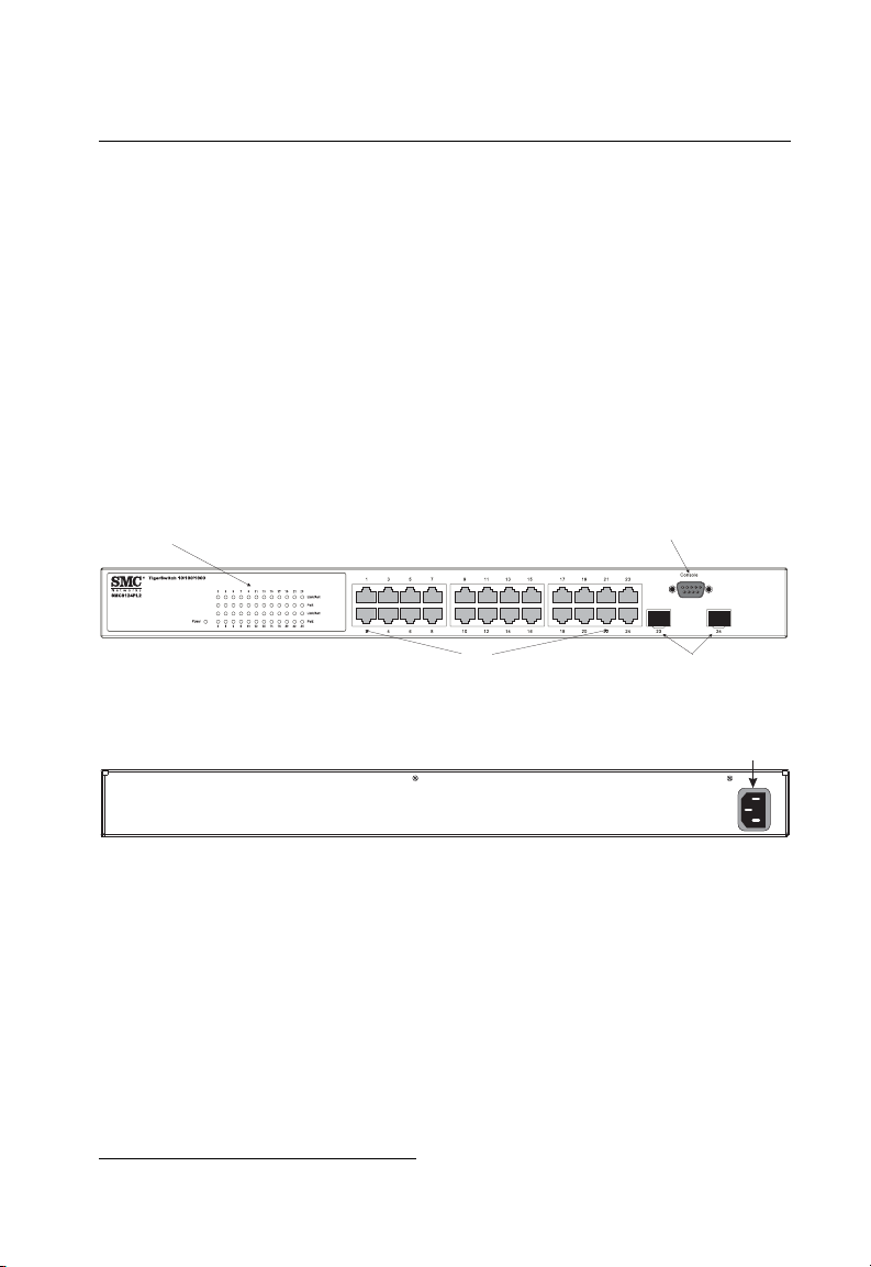
SMC’s TigerSwitch 10/100/1000 SMC8124PL2 is an intelligent Laye r 2 PoE sw itc h
with 24 10/100/1000BASE-T ports, two of which are combination ports
*
that are
shared with two SFP transceiver slots (see Figure 1-1, Ports 23-24).
The switch includes an SNM P-based management ag ent em bedded on the main
board, which supports both i n- band and out-of-band management access.
It can easily enhance yo ur net w or k wi th fu ll su pport for Spanning Tree Protocol,
multicast switching, and virt ual LANs. It brings order to po orly performing networks
by segregating them into separate broadcas t dom ains with IEEE 802.1Q compliant
VLANs, and empowers m ul t ime di a applications with multicas t swi tchi ng and CoS
services.
Port Status LEDs
10/100/1000 Mbps RJ-45 Ports
Figure 1-1 Front Panel
Figure 1-2 Rear Panel
Console Port
SFP Slots
Power Socket
100-240V~
3A50-60Hz
Switch Architecture
This Gigabit Ethernet swi t ch employs a wire-spee d, non-blocking switching fa br ic .
This permits simultaneous wire-speed transport of multiple packets at low latency on
all ports. The switch also features full-duplex capability on all ports, which effectively
doubles the bandwidth of each connection.
For communications wi t hi n th e sa me VLAN, the switch uses st ore-and-forward
switching to ensure maximum data integrity. The entire packet must be received into
* If an SFP transceiver is plugged in, the corresponding RJ-45 port is disabled for ports 23-24.
1-1
Page 22

About the TigerSwitch 10/100/1000
1
a buffer and checked for validity b ef or e bei ng forwarded. This prevents errors from
being propagated throug hout the network.
Power-over-Ethernet Capability
The switch’s 24 10/100/1000 Mbps ports support the IEEE 802.3a f
Power-over-Ethernet (PoE) standard that enables DC pow e r t o be s upplied to
attached devices using wire s i n th e connecting Ethernet cab le . An y 80 2. 3af
compliant device attached to a port can directly draw power from the switch over the
Ethernet cable without requiring its own separate power source. This capability gives
network administrators centralized power control for devices such as IP phones and
wireless access points, w hi ch tr ans l at es i nt o gr eater network availabi lity.
For each attached 802.3af-c ompliant device, the switch automatically senses the
load and dynamically supplies the required po wer. The switch del iver s power to a
device using wire pairs in the UTP or STP cable. Each port can provide up to 15.4 W
of power at the standard -48 VD C vol tage.
Network devices su ch as IP phones, wireless acc ess points, and network cameras,
typically consume less t han 10 W of power, so they are ideal for
Power-over-Ethernet applications.
Network Management Options
The switch contains a comprehensive array of LEDs for “at-a-glance” monitoring of
network and port status. It also i ncludes a management agent that allows you to
configure or monitor the swi tc h using its embedded manage m ent software, or via
SNMP appli cations. To manage the switch, you can m ake a direct c onnection to t he
console port (out-of- ban d), or you can manage it through a network connect io n
(in-band) using Telnet, the on-board web agent, or SNMP- based network
management software.
For a detailed description of the sw it ch’s ad vanced features, refer to the
Management Guide .
Description of Hardware
10/100/1000BASE-T Ports
The switch contains 24 RJ-45 ports that operate at 10 Mbps or 100 Mbps, half or full
duplex, or at 1000 Mbps, full duplex. Because all ports on the switch support
automatic MDI/MDI-X operation, you can use straight- through cables for all network
connections to PCs or servers, or to other switches or hubs. (See “1000BASE-T Pin
Assignments” on page B-3.)
1-2
Page 23

Description of Hardware
Each of these ports support auto-negotiation, so the opt i m um transmission mode
(half or full duplex), and data rate (10, 100, or 1000 Mbps) can be selected
automatically
†
.
SFP Slots
The Small Form Factor Pluggable (SFP) transceiver slots are shared with two of the
RJ-45 ports (ports 23-24). In its default co nf i gur at i on, i f an SF P t ran sc ei ver
(purchased separately) is in stalled i n a sl ot and has a valid link on its port, the
associated RJ-45 port is dis abl e d and cannot be used. The swit ch can also be
configured to force the use of an RJ-45 port or SFP slot, as required.
Port and System Status LEDs
The switch includes a display panel for key system and port indications that simplify
installation and network trou bl eshooting. The LEDs, which are located on the front
panel for easy viewing, are sh ow n b elow and described in the following tables.
RJ-45 Port Status LEDs
1
Power LED
Figure 1-3 Port and System LEDs
Table 1-1 Port Status LEDs
LED Condition Status
1-24
(Link/Activity/
Speed)
PoE Amber A PoE device is connected.
† The 1000BASE-T standard does not support forced mode. Auto-negotiation must always be
used to establish a connection over any 1000BASE-T port or trunk.
On/Flashing Amber Port has a valid link at 10 or 100 Mbps. Flashing
indicates activity.
On/Flashing Green Port has a valid link at 1000 Mbps. Flashing indicates
activity.
Off There is no link on the port.
Amber Blinking A PoE device is connected and data is being
transmitted.
Off No PoE device connected.
1-3
Page 24

About the TigerSwitch 10/100/1000
1
Table 1-2 System Status LEDs
LED Condition Status
Power Green Internal power is operating normally.
Amber Internal power supply fault.
Off Power off.
Power Supply Socket
The power socket on the rear panel of the switch must be connected to an AC power
source.
Figure 1-4 Power Supply Sockets
Features and Benefits
Connectivity
• 24 10/100/1000 Mbps ports for easy Gigabit Ethernet integration and for protection
of your investment in lega cy LAN equipment.
• Auto-negotiation enables each RJ-45 port to automat i cal ly select the optimum
communication mode (half or full duplex)
• RJ-45 10/100/1000BASE-T ports sup por t aut o M DI /MDI-X pinout selection.
• Unshielded (UTP) cable supported on all RJ-45 ports: Category 3 or better for
10 Mbps connect i ons, Category 5 or better for 100 Mbps connection s, and
Category 5, 5e, 6 or better for 1000 Mbps connections .
• IEEE 802.3-2005 Ethernet, Fast Ethernet, and Gigabit Ethern et com pliance
ensures compatibilit y w i th sta ndards-based hubs, net w or k cards and switches
from any vendor.
‡ 1000BASE-T ports do not support forced mode.
1-4
‡
.
Page 25

Features and Benefits
Expandability
• Supports 1000BASE-SX, 1000BASE-LX an d 1000BASE-ZX SFP transceivers.
Performance
• Transparent bridging.
• Aggregate duplex bandwidt h of up to 48 Gbps.
• Switching table with a total of 8K M AC ad dress entries.
• Provides store-and-forward switching for intra-VLAN traffic.
• Supports wire-speed switching.
Management
• “At-a-glance” LEDs for easy troubleshooting.
• Network management ag ent
• Manages switch (or entire stack) in-band or out-of-band
• Supports console, Telnet, SSH, SNMP v1/ v2c, RMON (4 grou ps) and
web-based interface
1
1-5
Page 26

About the TigerSwitch 10/100/1000
1
1-6
Page 27

Chapter 2: Network Planning
Introduction to Switching
A network switch allows simultaneous transmission of multiple packets via
non-crossbar switching. This means that it ca n parti tion a net w ork more efficiently
than bridges or routers. The switch has, therefor e, been recognized as one of th e
most important building blocks for today’s networking tec hnology.
When performance bottlenecks are caused by congestion at the network access
point (such as the network c ard for a high-volume file server), the device
experiencing congest i on (server, power user or hub) can be attached dir ect l y to a
switched port. And, by using full-duplex mode, the bandwidth of the dedicated
segment can be doubl ed t o m ax im ize throughput.
When networks are bas ed on repeater (hub) technology, the distance between end
stations is limited by a maxim um hop count. However, a switch turns the ho p count
back to zero. So subdividi ng the network into smalle r an d m or e m anageable
segments, and linking them to the larger network by means of a switch, removes this
limitation.
A switch c an be ea sil y co nfig ured in an y Et hern et, Fast Ether net , or Giga bit Ether net
network to significantly boost bandwidth while using conventional cabling an d
network card s.
Application Examples
The TigerSwitch 10/100/1000 is no t on ly designed to segment yo ur net wor k, but
also to provide a wide range of options in setting up netw o rk connections. Some
typical applications are described below.
Collapsed Backbone
The TigerSwitch 10/100/1000 is an exce l le nt choice for mixed Ethernet, Fa st
Ethernet, and Gigabit Ether net installations where signifi can t growth is expected in
the near future. In a basic stand-alone configuration, it can provide direct full-duplex
connections for up to 24 w or kstati ons or servers. You can easily build on this basic
configuration, adding direct full-duplex connections to workstations or servers. When
the time comes for further expansion, just connect to anot her hub or switch using
one of the Gigabit Ethernet ports built into the front panel, or a Gigabit Ethernet port
on a plug-i n SF P transceiver.
In the following figure, the 24-port switch is operating as a collapsed backbone for a
small LAN. It is providing de di cat ed 10 Mbps full-duplex connections to
2-1
Page 28

Network Planning
2
workstations, 100 Mbps full-duplex connections to pow e r us ers, and 1 Gbps
full-duplex connections to servers. In addition, connected IP phones and wir el es s
access points are receiving PoE power from the switch.
...
Servers
1 Gbps
Full Duplex
...
Workstations
100 Mbps
Full Duplex
...
Workstations
10 Mbps
Full Duplex
Power-over-Ethernet Devices
10/100 Mbps
Full Duplex
Figure 2-1 Collapsed Backbone
Network Aggregation Plan
With 24 parallel bridging por ts (i.e., 24 distinct collision domai ns), a Gigabit switch
can collapse a complex network down into a single efficient bridged node, increasing
overall bandwidth and throu gh put .
In the figure below, the 10/100/1000BASE-T por ts are pr ovi ding 1000 Mbps
connectivity through cascaded switches. In ad dition, the switches are also
connecting severa l se rv er s at 1 G bps.
Server Farm
10/100/1000 Mbps Segments
...
...
2-2
Figure 2-2 Network Aggregation Plan
Page 29

Application Examples
Remote Connections with Fiber Cable
Fiber optic technology allo w s fo r longer cabling than any oth er me dia ty pe. A
1000BASE-SX (MMF) link can conn ect to a site up to 550 meter s awa y, a
1000BASE-LX (SMF) link up to 5 km, and a 1000BASE-ZX link up to 100 km. This
allows a switch to serve as a collapsed backbone, providing direct connectivity for a
widespread LAN.
A 1000BASE-SX SFP transceiver can be used for a high-speed connection between
floors in the same building. For long-haul connections, a 1000 BASE-ZX SFP
transceiver can be used to reach another site up to 10 0 kil om et er s away.
The figure below illustra tes t hree TigerSwitch 10/100/1000 units int erc onnecting
multiple segments with fiber cable.
Headquarters
Warehouse
45 46 47 48
45 46 47 48
TigerSwitch10/100/1000
8048L2
PWR
46 48
45
47
RPS
48
Diag
46
Console
TigerSwitch10/100/1000
8048L2
PWR
46 48
45
47
RPS
48
Diag
46
Console
Server Farm
Remote Switch
12 3 4 56 7 891011 12 13 1415 16 1718 1920 21 22 23 24 373839 40 4142 4344 45 4647 482526 2728 29 30 31 32 33 34 3536
...
1000BASE-SX MMF
(500 meters)
Remote Switch
StackMaster
Pwr
RPS
TigerStackII
10/100/1000
Module
Diag
8848M
Master
StackID
Console
Select
StackLink
45 464748
12 3 4 56 7 891011 12 13 1415 16 1718 1920 21 22 23 24 373839 40 4142 4344 45 4647 482526 2728 29 30 31 32 33 34 3536
10/100/1000 Mbps Segments
1000BASE-LX SMF
(5 kilometers)
StackMaster
Pwr
RPS
TigerStackII
10/100/1000
Module
Diag
8848M
Master
StackID
Console
Select
StackLink
45 464748
...
1000BASE-LX SMF
(5 kilometers)
...
Research & Development
2
...
Figure 2-3 Remote Connections with Fiber Cable
Making VLAN Connections
This switch supports VLANs which can be used to organize any group of network
nodes into separate broadcast domains . VLANs confine br oadcast traffic to the
originating group, and can eliminate broadcast storms in large networks. This
provides a more secure and cleaner network environment.
VLANs can be based on untagg ed port groups, or traffic can be explicitly tagged t o
identify the VLAN group to which it belongs. Untagged VLANs can be used for small
networks attached to a single sw i tch. However, tagged VLANs should be used for
larger networks, and all th e VLANs assigned to the int er -s w itc h links.
2-3
Page 30

Network Planning
2
R&D
VLAN 1
Tagged
Testing
VLAN 2
Ports
Finance
VLAN 3
VLAN 4
Untagged Ports
Marketing
VLAN
unaware
switch
Finance
VLAN 3
Tagged Port
VLAN 1
R&D
VLAN 2
Figure 2-4 Making VLAN Connections
Note: When connecting to a switch that does not support IEEE 802.1Q VLAN tags, use
untagged ports.
Application Notes
1. Full-duplex operation only applies to point-to-point access (such as when a
switch is attached to a workstation, server or another switch). When the switch
is connected to a hub, both devices must operate i n hal f-duplex mode.
2. For network applications that require routing between dissimilar network types,
you can attach these switch es directly to a multi-proto col ro ut er.
VLAN
aware
switch
Testing
3. As a general rule, the length of fiber optic cable for a single switched link should
not exceed:
• 1000BASE-SX: 550 m (1805 ft) for multimode fiber
• 1000BASE-LX: 10 km (3.1 miles) for single-mode fiber
• 1000BASE-ZX: 80 km (62.1 miles) for single-mode fiber
However, power budget constraints must al so be considered when ca lc ul at ing the
maximum cable length for your specific environment.
2-4
Page 31

Chapter 3: Installing the Switch
Selecting a Site
TigerSwitch 10/100/1000 units can be mounted in a standard 19-inch equipment
rack or on a flat surface. Be sur e t o fo llo w the gui delines below when choosing a
location.
• The site should:
• be at the center of all the devices you want to l in k an d near a power outlet.
• be able to maintain its temperature within 0 t o 45 °C (32 to 113 °F) and its
humidity within 10% to 90 % , n on- condensing
• provide adequate space (approximately five centimete rs or tw o i nches) on all
sides for proper air flow
• be accessible for installing, cabling and maintaining the devices
• allow the status LEDs to be clearly visible
• Make sure twisted-pair cable is always routed away from power lines, fluorescent
lighting fixtures and other sources of electrical interf er ence, such as radios and
transmitters.
• Make sure that the unit is connec ted t o a separate grounded pow er out l et th at
provides 100 to 240 VAC, 50 to 60 Hz, is within 2 m (6.6 feet) of each device and
is powered from an independent circuit bre aker. As with any equipment, usi ng a
filter or surge suppressor is re com mended.
Ethernet Cabling
To en su re proper operation whe n i nstalli ng t he switch in a network, mak e sure that
the current cables are suitable for 10BASE-T, 100BASE-TX or 1000BASE-T
operation. Check the fol l owi ng criteria against the curr ent in stallat i on of your
network:
• Cable type: Unshielded twisted pair (UTP) or shielded twisted pair (STP) cables
with RJ-45 connectors; Category 3 or better for 10BASE-T, Categ ory 5 or better
for 100BASE-TX, and Category 5, 5e or 6 for 1000BASE-T.
• Protection from radio frequency interference emissions
• Electrical surge suppression
• Separation of electrical wires (switch related or other) and electromagnetic fields
from data based networ k w iring
• Safe connections with no damaged cables, conne ctors or shields
3-1
Page 32

Installing the Switch
3
RJ-45 Connector
Figure 3-1 RJ-45 Connections
Equipment Checklist
After unpacking the TigerSwitch 10/100/1000 unit, check the contents to be sure you
have received all the com ponents. Then, before begin ning the installation, be sure
you have all other necess ar y i nsta llati on equipment.
Package Contents
• TigerSwitch 10/100/1000 unit (SM C8124PL2)
• Four adhesive foot pads
• Bracket Mounting Kit containing two brackets and eight screws for attaching the
brackets to the switch
• Power cord—either US, Continental Europe or UK
• Console cable (RS-232)
• This Installation Guide
• Documentation CD
• SMC Warranty Registrati on C ard
Optional Rack-Mounting Equipment
If you plan to rack-mount the switch, be sure to have the following equipment
available:
• Four mounting screws for each device you plan to install in a rack—these are not
included
• A screwdriver (Phillips or flathe ad, depending on the type of scr ew s used)
3-2
Page 33

Mounting
Mounting
A TigerSwitch 10/100/1000 unit can be mounted in a standard 19-inc h equipment
rack or on a desktop or shelf. Mounting instructions for each type of site follow.
Rack Mounting
Before rack mounting th e swi t ch, pay particular attention to the foll owi ng factors:
• Temperature: Since the temperature within a rack as se mbly may be higher than
the ambient room temper at ur e, check that the rack-envi ro nm ent temperature is
within the specified oper at in g te m pe rature range (see page -1).
• Mechanical Loading: Do not place any equipment on to p of a rack-mounted unit.
• Circuit Overloading: Be sure that the supply circuit to the rack assembly is not
overloaded.
• Grounding: Rack-mounted equipment should be prop erly grounded. Particular
attention should be give n t o sup pl y connections other than direct connections to
the mains.
To rack-mount devices:
1. Attach the brackets to the dev i ce us i ng t he screws provided in the Bra ck et
Mounting Kit.
3
Figure 3-2 Attaching the Brackets
2. Mount the dev ice i n th e ra ck, using four rack-mount i ng screws (not provided).
3-3
Page 34

Installing the Switch
3
Figure 3-3 Installing the Switch in a Rack
3. If installing a single swit ch only, turn to “Connecting to a Power Source” at the
end of this chapter.
4. If installing multiple switches, mount them in the rack, one below the other, in
any order.
Desktop or Shelf Mounting
1. Attach the four adhesive feet to the bottom of the first switch.
Figure 3-4 Attaching the Adhesive Feet
3-4
Page 35

Installing an SFP Transceiver
2. Set the device on a f la t surf ac e near an AC power source, making sure there
are at least two inches of spac e on al l si des for proper air flow.
3. If installing a single swit ch only, go to “Connecting to a Power Source” at the
end of this chapter.
4. If installing multiple switches, attach four adhesive feet to each one. Place each
device squarely on top of t he one below, in any order.
Installing an SFP Transceiver
3
Figure 3-5 Inserting an SFP Transceiver into a Slot
The switch support the following optional transceivers:
• 1000BASE-SX (SMC1GSFP-SX)
• 1000BASE-LX (SMC1GSFP-LX)
• 1000BASE-ZX (SMC1GSFP-ZX)
To install an SFP transceiver, do the following:
1. Consider network and cabling requirements to select an appropriate transceiver
type. Refer to “Connect ivi t y R ules” on page 4-5.
2. Insert the transceiver with the optical co nnector facing outward and the slot
connector facing down. N ot e th at SFP t ransceivers are keyed so the y can only
be installed in one orientation.
3. Slide the transcei ve r int o t he slot until it clicks into place.
Note: SFP transceivers are hot-swappable. The switch does not need to be powered off
before installing or removing a transceiver. However, always first disconnect the
network cable before removing a transceiver.
3-5
Page 36

Installing the Switch
3
Connecting to a Power Source
To connect a device to a power source:
1. Insert the pow er cabl e plug directly into the socket located at the back of the
device.
Figure 3-6 Power Socket
2. Plug the other end of the c abl e int o a gr ounded, 3-pin, AC power s our ce.
Note: For international use, you may need to change the AC line cord. You must use a
line cord set that has been approved for the socket type in your country.
3. Check the front- panel LED s as t he device is powered on to be sur e the Power
LED is on. If not, check that the power cable is correctly plugged in.
Connecting to the Console Port
The DB-9 serial port on the switch’s rear panel is used to connect to the switch for
out-of-band console configuration. The comm and-line-driven confi gur at ion program
can be accessed from a terminal or a PC running a terminal emulation program. The
pin assignments used to connect to the serial port are provided in the following table.
1
6 9
Figure 3-7 Serial Port (DB-9 DTE) Pin-Out
3-6
5
Page 37

Connecting to the Console Port
Wiring Map for Serial Cable
Table 3-1 Serial Cable Wiring
Switch’s 9-Pin
Serial Port
2 RXD (receive data) <---------------------------- 3 TXD (transmit data)
3 TXD (transmit data) ----------------------------> 2 RXD (receive data)
5 SGND (signal ground) ------------------------------ 5 SGND (signal ground)
No other pins are used.
The serial port’s configuration requirements are as follows:
• Default Baud rate—9,600 bps
• Character Size—8 Characters
• Parity—None
• Stop bit—One
• Data bits—8
• Flow co nt rol—none
Null Modem PC’s 9-Pin
DTE Port
3
3-7
Page 38

Installing the Switch
3
3-8
Page 39

Chapter 4: Making Network Connections
Connecting Network Devices
The TigerSwitch 10/100/1000 units are designed to interconnect multiple segments
(or collision domains). It can be connected to network cards in PCs and servers, as
well as to hubs, switche s or routers. It may also be co nnected to devices usin g
optional SFP transceivers.
Twisted-Pair Devices
Each device requires an unshielded twisted-pair (UTP) cable with RJ-45 connectors
at both ends. Use Category 5, 5e or 6 cable for 1000BASE-T connections, Category
5 or better for 100BASE-TX connections, and Categ ory 3 or better for 10B ASE- T
connections.
Power-over-Ethernet Connections
The PoE switch automa tic al ly det ects an 802.3af-compliant device by its
authenti cated PoE signature and senses its required l oad before turning on DC
power to the port. This detection mechanism prevents damage to other network
equipment that is not 802. 3af compliant.
Note: Power-over-Ethernet connections work with all existing Category 3, 4, 5, 5e or 6
network cabling, including patch cables and patch-panels, outlets, and other
connecting hardware, without requiring modification.
The switch delivers power to a device using wire pairs in the connecting UTP or STP
cable. The switch can pro vi de up to 15.4 W of power conti nuously on each port.
However, taking into account some power loss over the cable run, the amount of
power that can be delivered to a terminal device is 1 2.95 W.
The switch controls the po wer and data on a port independently. Power can be
requested from a device that already has a data link to the switch. Also, the swit ch
can supply power to a dev ic e ev en i f the port’s data connection has been di sa bl ed.
The power on a port is continuousl y monitored by the switch and it w ill be tu rn ed off
as soon as a device connection is removed.
Cabling Guidelines
The RJ-45 ports on the switch support automatic MDI/MDI-X pinout configuration, so
you can use standard straig ht -through twisted-pair cables to connect to any other
network device (PCs, servers, switches, router s, or hubs).
4-1
Page 40

Making Network Connections
4
See Appendix B: for further information on cabling.
Caution: Do not plug a phone jack connector into an RJ-45 por t . Th is will
damage the switch. Use only twisted-pair cables wit h R J- 45 connectors
that conform to FCC standards.
Connecting to PCs, Servers, Hubs and Switches
1. Attach one end of a twis ted-pair cable segment to the de vi ce’s RJ -4 5
connector.
Figure 4-1 Making Twisted-Pair Connections
2. If the device is a PC card and the switch is in the wiring closet, attach the other
end of the cable segment to a modular wall outlet that is connected to the wiring
closet. ( S ee “Network Wir ing Connections” on page4- 2.) Otherwis e, attach the
other end to an available po rt on the switch.
3. Make sure each twisted pair cable does not exceed 100 meters (328 ft) in
length.
4. As each connec tio n is ma de, the Link LED (on the switch) cor re sponding to
each port will light green (1000 Mbps) or amber (10/100 Mbps) to indicate that
the connection is valid .
Network Wiring Connections
To day, the punch-down bl ock is an integral part of many of the ne w er equipment
racks. It is actually part of the patch panel. Instructions for making connections in the
wiring closet with this type of equipment follows.
4-2
Page 41

Fiber Optic SFP Devices
witch10/100
6724L3
1. Attach one end of a patch cable to an available port on the switch, and the other
end to the patch panel.
2. If not already in place, attach one end of a cable seg m ent t o th e back of the
patch panel where the punch-down block is located, and the other end to a
modular wall outlet.
3. Label the cables to sim plify future troubleshoo ting . See “ Cable Labeling and
Connection Records ” on page 4-6.
Equipment Rack
(side view)
Network Switch
4
2
5
4
S
E
C
Punch-Down Block
Patch Panel
4
Wall
Figure 4-2 Wiring Closet Connections
Fiber Optic SFP Devices
An optional Gigabit SFP transceiver (1000BASE-SX, 1000BASE-LX or
1000BASE-ZX) can be used for a bac kbone connection between sw itch es, or for
connecting to a high-speed server.
Each single-mode fiber port requires 9/125 micron single-mode fiber optic cable with
an LC connector at both ends. Each multimode fiber optic port requires 50/125 or
62.5/125 micron multi m ode fiber optic cabling with an LC connector at both ends.
4-3
Page 42

Making Network Connections
4
Caution: This switch uses lasers to transmit signals over fiber optic cable. The lasers are
compliant with the requirements of a Class 1 Laser Product and are inherently
eye safe in normal operation. However, you should never look directly at a
transmit port when it is powered on.
Note: When selecting a fiber SFP device, considering safety, please make sure that it
can function at a temperature that is not less than the recommended maximum
operational temperature of the product. You must also use an approved Laser
Class 1 SFP transceiver.
Note: Bei der Wahl eines Glasfasertransceivers muß für die Beurteilung der
Gesamtsicherheit beachtet werden, das die maximale Umgebungstemperatur des
Transceivers für den Betrieb nicht niedriger ist als die für dieses Produkts. Der
Glasfasertransceiver muß auch ein überprüftes Gerät der Laser Klasse 1 sein.
1. Remove and keep the LC port’s rubber cover. When not conn ect ed to a fiber
cable, the rubber cove r sh oul d be replaced to protect the op t ic s.
2. Check that th e fiber terminators are clean. You can clean the cable plugs by
wiping them gently with a cl ean tissue or cotton ball m oist ened with a little
ethanol. Dirty fiber term inat or s on fiber cables will impair the qu al ity of the light
transmitted through th e cable and lead to degraded performance on the port .
3. Connect one end of the cable to the LC port on the switch and the other end to
the LC port on the other device . Since LC connectors are ke yed, the cable can
be attached in only one orientation .
4.
Figure 4-3 Making Connections to SFP Transceivers
5. As a connection is made, check the Link LED on t he switch corresponding t o
the port to be sure that the connection is valid.
4-4
Page 43

Connectivity Rules
The 1000BASE-SX, 1000BASE- LX an d 1000BASE-ZX fiber optic ports operate at
1 Gbps full duplex. The m aximum length for fiber op tic c abl e operating at Gigabit
speed will depend on the fiber type as listed under “1000 Mbps Gigabit Ethernet
Collision Domain” on page 4-5.
Connectivity Rules
When adding hubs (re peaters) to your network, pl ease follow the connecti vi ty ru le s
listed in the manuals for these products. However, note that because switches break
up the path for connected devices into separate collision domains, you should not
include the switch or connected cabling in your ca lc ul at ions for cascade length
involving other device s.
1000BASE-T Cable Requirements
All Category 5 UTP cables that are used for 100BASE-TX connections should also
work for 1000BASE-T, providing that all four wire pairs are connected. However, it is
recommended tha t for all cr itical connections, or any new cable installations,
Category 5e (enhanced Category 5) or Categor y 6 c abl e should be used. The
Category 5e specifica tio n in cl udes test parameters that are only recommendation s
for Category 5. Therefor e, the firs t ste p in pr eparing existing Category 5 cabling for
running 1000BASE-T is a sim pl e t est of th e cable installation to be sure that it
complies with the IEEE 802. 3- 2005 standards.
4
1000 Mbps Gigabit Ethernet Collision Domain
Table 4-1 Maximum 1000BASE-T Gigabit Ethernet Cable Length
Cable Type Maximum Cable Length Connector
Category 5, 5e, 6 100-ohm UTP or STP 100 m (328 ft) RJ-45
Table 4-2 Maximum 1000BASE-SX Fiber Optic Cable Length
Fiber Diameter Fiber Bandwidth Ca ble Length Range Connector
62.5/125 micron multimode
fiber (MMF)
50/125 micron multimode fiber
(MMF)
160 MHz/km 2-220 m (7-722 ft) LC
200 MHz/km 2-275 m (7-902 ft) LC
400 MHz/km 2-500 m (7-1641 ft) LC
500 MHz/km 2-550 m (7-1805 ft) LC
4-5
Page 44

Making Network Connections
4
Table 4-3 Maximum 1000BASE-LX Fiber Optic Cable Length
Fiber Diameter Fiber Bandwidth Cable Length Range Connector
9/125 micron single-mode fiber N/A 2 m - 5 km
Table 4-4 Maximum 1000BASE-ZX Fiber Optic Cable Length
Fiber Diameter Fiber Bandwidth Cable Length Range Connector
9/125 micron single-mode fiber N/A 70* - 100 km
* For link spans exceeding 70 km, you may need to use premium single mode fiber or dispersion
shifted single mode fiber
(7 ft - 3.2 miles)
(43.5 - 62.1 miles)
100 Mbps Fast Ethernet Collision Domain
Table 4-5 Maximum Fast Ethernet Cable Length
Type Cable Type Maximum Cable Length Connector
100BASE-TX Category 5 or better 100-ohm
UTP or STP
100 m (328 ft) RJ-45
10 Mbps Ethernet Collision Domain
LC
LC
Table 4-6 Maximum Ethernet Cable Length
Type Cable Type Maximum Length
10BASE-T Categories 3, 4, 5 or better
100-ohm UTP
100 m (328 ft) RJ-45
Connector
Cable Labeling and Connection Records
When planning a network installation, it is essential to la bel th e op posing ends of
cables and to record where each cable is connected. Doing so will enable you to
easily locate inter-con nected devices, isolate f aul ts an d cha nge your topology
without need for unnecessary time consumpt ion.
To best m anage the physical impl em e ntat ions of your network, follow th ese
guidelines:
• Clearly label the opposing ends of ea ch cable.
• Using your building’s floor plans, dr aw a m ap of the location of all
network-connected equipment. For each piece of equipment, identify the devices
to which it is connected.
4-6
Page 45

Cable Labeling and Connection Records
• Note the length of each cable and the maximum cable length supported by the
switch ports.
• For ease of understanding, use a location-based ke y w he n assigning prefixes to
your cable labeling.
• Use sequential numbers for c ables that originate from the sam e equipment.
• Differentiate between racks by naming accordingly.
• Label each separate piece of equipment.
• Display a copy of your equipment map, including keys to all abbreviations at each
equipment rack.
4
4-7
Page 46

Making Network Connections
4
4-8
Page 47

Appendix A: Troubleshooting
Diagnosing Switch Indicators
Table A-1 Troubleshooting Chart
Symptom Action
Power LED is Off • Check connections between the switch, the power cord, and the wall
outlet.
• Contact your dealer for assistance.
• Contact SMC Technical Support.
Power LED is Amber • Internal power supply has failed. Contact your local dealer for
assistance.
Link LED is Off • Verify that the switch and attached device are powered on.
• Be sure the cable is plugged into both the switch and corresponding
device.
• Verify that the proper cable type is used and its length does not exceed
specified limits.
• Check the adapter on the attached device and cable connections for
possible defects. Replace the defective adapter or cable if necessary.
Power and Cooling Problems
If the power indicator does not turn on when the powe r c or d is pl ugg ed i n, you may
have a problem with the pow er outlet, power cord, or inter nal power supply.
However, if the unit powers off after running for a while, check for loose power
connections, power lo sses or surges at the power out l et , an d verify that the fans on
the unit are unobs tr ucte d and runn ing pri or to shu td own. If y ou s ti ll c annot is olat e t he
problem, then the intern al pow er supply may be defec tiv e.
Installation
Verify that all system components have bee n pr operly installed. If one or more
components appear to be malfunctioning (such as the power cord or network
cabling), test them in an alternate environment where you ar e sur e th at all the oth er
components are functioning properly.
A-1
Page 48

A
Troubleshooting
In-Band Access
You can access the m an agement agent in the sw itch from anywhere within the
attached network using Telnet, a Web browser, or other network management
software tools. However, you must first co nf ig ur e t he switch with a valid IP address,
subnet mask, and defau lt gateway. If you have trouble establishing a link to the
management agent, check to see if you have a valid net w or k connection. Then
verify that you entered the correct IP address. Also, be sure the port through which
you are connecting to th e swi t ch has not been disabled. If it ha s not been disabled,
then check the network cabling that runs between your remote location and the
switch.
Caution: The management agent can accept up to four simultaneous Telnet
sessions. If the maximum number of sessions already exists, an additional
Telnet connection will not be ab l e to lo g into th e system.
A-2
Page 49

Appendix B: Cables
Twisted-Pair Cable and Pin Assignments
For 10BASE-T/100BASE-TX conne ctions, a twisted-pair cable must have two pairs
of wires. For 1000BASE-T connections the twisted-pair cable must have four pairs of
wires. Each wire pair is identifie d by two different colors. For exampl e, one wire
might be green and the othe r, green with white stri pes . Also, an RJ-45 connector
must be attached to both ends of the cable.
Caution: Each wire pair must be attached to the RJ-45 connectors in a specific
orientation.
Caution: DO NOT plug a phone jack connector into any RJ-45 port. Use only
Figure B-1 illustrates how the pins on the RJ-45 connector are numbered. Be sure to
hold the connectors in the sam e orientation when attaching the w ires to the pins.
twisted-pair cables with RJ-45 connectors that conform with FCC standards.
8
1
Figure B-1 RJ-45 Connector Pin Numbers
8
1
10BASE-T/100BASE-TX Pin Assignments
Use unshielded twisted-pair (UTP) or shielded twisted-pair (STP) cable for RJ-45
connections: 100-oh m Ca te gory 3 or better cable for 10 M bps connections, or
100-ohm Category 5 or better cable for 100 Mbps connections. Also be sure that the
length of any twisted-pair connection does not exceed 100 meters (328 feet).
The RJ-45 ports on the switch base unit support automatic MDI/MDI-X operation, so
you can us e s trai ght -thr ough ca bles for all net wor k con nec tion s to PCs or s erve rs, or
to other switches or hubs. In straight-through cable, pins 1, 2, 3, and 6, at one end of
the cable, are connected straight through to pins 1, 2, 3, and 6 at the oth er end of
the cable. When using any R J-45 port on the switch, y ou ca n use either
straight-through or c ro ssover cable.
B-1
Page 50

B
Cables
Table B-1 10/100BASE-TX MDI and MDI-X Port Pinouts
Pin MDI Signal Name MDI-X Signal Name
1 Receive Data plus (RD+)
2 Receive Data minus (RD-) and
and GND (Positive V
and GND (Positive V
port
port
)
)
3 Transmit Data plus (TD+)
and -48V feeding power (Negative V
6 Transmit Data minus (TD-)
and -48V feeding power (Negative V
Transmit Data plus (TD+)
and -48V feeding power (Negative V
Transmit Data minus (TD-)
and -48V feeding power (Negative V
Receive Data plus (RD+)
)
and GND (Positive V
port
Receive Data minus (RD-)
)
and GND (Positive V
port
port
port
port
port
)
)
4, 5, 7, 8 not used not used
Note: The “+” and “-” signs represent the polarity of the wires that make up each wire pair.
Straight-Through Wiring
If the twisted-pair cable is to join two ports and only one of the ports has an int er nal
crossover (MDI-X), th e two pairs of wires must be straigh t- t hr ough. (When
auto-negotiation is enabled for any RJ-45 port on t his sw i t ch , yo u can use either
straight-through or c ro ssover cable to connect to an y device type.)
You must connect all fou r wi r e pairs as shown in the following diagra m to support
Gigabit Ethernet connec tions.
)
)
B-2
End A
EIA/TIA 568B RJ-45 WiringStandard
10/100BASE-TX Straight-through Cable
White/Orange Stripe
Orange
1
2
3
4
5
6
7
8
White/Green Stripe
Blue
White/Blue Stripe
Green
White/Brown Stripe
Brown
Figure B-2 Straight-through Wiring
1
2
3
4
5
6
7
8
End B
Page 51

Twisted-Pair Cable and Pin Assignments
B
Crossover Wiring
If the twisted-pair cable is to join two ports and either both ports are labe led w i th an
“X” (indicating MDI-X) or neither port is labeled with an “X” (which indicates MDI), a
crossover must be implemented in the wiring. (When auto-negotiation is enabled for
any RJ-45 port on this switch, you can use either straight-through or crossover cable
to connect to any device type.)
You must connect all fou r wi r e pairs as shown in the following diagra m to support
Gigabit Ethernet connec tions.
EIA/TIA 568B RJ-45 Wiring Standard
10/100BASE-TX Crossover Cable
White/Orange Stripe
Orange
End A
1
2
3
4
5
6
7
8
White/Green Stripe
Blue
White/Blue Stripe
Green
White/Brown Stripe
Brown
Figure B-3 Crossover Wiring
1
2
3
4
5
6
7
8
End B
1000BASE-T Pin Assignments
All 1000BASE-T ports support automatic MDI/MDI-X operation, so yo u ca n use
straight-through cab les f or all net work connections to PCs or se rv er s, or to ot her
switches or hubs.
The table below shows the 1000BASE-T MDI and MDI-X port pinouts. These ports
require that all four pairs of wires be connected. Note that for 1000BASE-T
operation, all four pairs of wires ar e used for both transmit and r eceive.
Use 100-ohm Category 5, 5e or 6 unshielded twiste d- pair (UTP) or shielded
twisted-pair (STP) cable for 1000BASE-T connections. Also be sure that the length
of any twisted-pair connection does not exceed 100 m et er s (3 28 feet).
Table B-2 1000BASE-T MDI and MDI-X Port Pinouts
Pin MDI Signal Name MDI-X Signal Name
1 Bi-directional Data Two Plus (BI_D2+) Bi-directional Data One Plus (BI_D1+)
2 Bi-directional Data Two Minus (BI_D2-) Bi-directional Data One Minus (BI_D1-)
3 Bi-directional Data One Plus (BI_D1+) Bi-directional Data Two Plus (BI_D2+)
B-3
Page 52

B
Cables
Table B-2 1000BASE-T MDI and MDI-X Port Pinouts
Pin MDI Signal Name MDI-X Signal Name
4 Bi-directional Data Four Plus (BI_D4+) Bi-directional Data Three Plus (BI_D3+)
5 Bi-directional Data Four Minus (BI_D4-) Bi-directional Data Three Minus (BI_D3-)
6 Bi-directional Data One Minus (BI_D1-) Bi-directional Data Two Minus (BI_D2-)
7 Bi-directional Data Three Plus (BI_D3+) Bi-directional Data Four Plus (BI_D4+)
8 Bi-directional Data Three Minus (BI_D3-) Bi-directional Data Four Minus (BI_D4-)
Cable Testing for Existing Category 5 Cable
Installed Category 5 cabling must pass tests for Attenuation, Near-End Crosstalk
(NEXT), and Far-End Crosstalk (FEXT). This cable testing information is specified in
the ANSI/TIA/EIA-TSB-67 standard. Additionally, cables must also pass test
parameters for Return Loss and Equal-Level Far-End Crosstalk (ELFEXT). These
tests are specified in the ANSI/TIA/EI A- TSB-95 Bulletin, “The Addition al
Transmission Performance Guidelines for 100 Ohm 4-Pair Category 5 Cabling.”
Note that when testing your cable installation, be sure to inc l ude all patch cables
between switches and end devices.
Adjusting Existing Category 5 Cabling to Run 1000BASE-T
If your existing Category 5 installation does not meet on e of th e te st parameters for
1000BASE-T, there are basically three measures that can be applied to try and
correct the problem:
1. Replace any Category 5 patch cables with hig h- per f or m ance Category 5e or
Category 6 cables.
2. Reduce the number of connectors used in the link.
3. Reconnect so m e of th e connectors in the link.
Fiber Standards
The current TIA (Telecommunications Industry Association) 568-A specification on
optical fiber cabling consists of one recognized cable type for horizontal subsystems
and two cable types for backbone subsystems.
Horizontal 62.5/125 micron multim ode (two fibers per outlet).
Backbone 62.5/125 micron multimode or single mode.
TIA 568-B will allow the use of 50/125 micron multimode optical fiber in both the
horizontal and backbone in ad di tion to the types listed above. All opt ical fiber
components and installation pra ct ices must meet applicab le buil di ng and safety
codes.
B-4
Page 53

Appendix C: Specifications
Physical Characteristics
Ports
22 10/100/1000BASE-T, with auto-negotiation
2 10/100/1000BASE-T shared w ith 2 SFP transceiver slots.
Network Interface
Ports 1-24: RJ-45 connector, auto MDI/X
10BASE-T: RJ-45 (100-ohm, UTP cable; Category 3 or better )
100BASE-TX: RJ-45 (100-ohm, UTP cable; Category 5 or better)
1000BASE-T: RJ-45 (100-ohm, UTP or STP cable; Categor y 5, 5e, or 6)
*Maximum Cable Length - 100 m (328 ft)
Buffer Architecture
768 Kbytes
Aggregate Bandwidth
48 Gbps
Switching Database
8K MAC address entries, 1K sta tic MA C a ddr esses
LEDs
System: Power
Port: Status (link, speed, activity); PoE
Weight
4.33 kg (9.53 lbs)
Size
44 x 32 x 4.3 cm (17.3 x 12.6 x 1.7 i n. )
Temperature
Operating: 0 to 45 °C (32 to 113 °F)
Storage: -40 to 70 °C (-40 to 158 °F)
Humidity
Operating: 10% to 90% (n on- condensing)
C-1
Page 54

C
Specifications
AC Input
100 to 240 V, 50-60 Hz, 3A
Power Supply
Internal, auto-rangin g transformer: 100 to 240 VAC, 47 to 63 Hz
Power Consumption
45 W (switch system)
180 W (Power over Ethernet)
Switch Features
Forwarding Mode
Store-and-forward
Throughput
Wire speed
Management Features
In-Band Management
Web, Telnet, SSH, or SNMP manager
Out-of-Band Management
RS-232 RJ-45 console port
Software Loading
TFTP in-band, or XModem ou t-of- band
Standards
IEEE 802.3-2005
Ethernet, Fast Ethernet, Gigabit Ethernet
IEEE 802.1D Spanning Tree Protocol
IEEE 802.1w Rapid Spanning Tree Protocol
IEEE D802.1Q Virtual LAN
ISO/IEC 8802-3
C-2
Page 55

Compliances
CE Mark
Emissions
FCC Class A
Industry Canada Clas s A
EN55022 (CISPR 22) Class A
EN 61000-3-2/3
VCCI Class A
C-Tick - AS/NZS 3548 (1995) Class A
Immunity
EN 61000-4-2/3/4/5/6/8/11
Safety
UL (No. 60950-1 & UL 60905- 1)
CB (IEC/EN 60950-1)
Warranty
Limited Lifetime
Compliances
C
C-3
Page 56

C
Specifications
C-4
Page 57

Appendix D: German Instructions
Eine Site Auswählen (Selecting a Site)
Die Schalter können in ein Standard-19-Zoll-Ausrüstungsgestell oder auf eine flache
Ebene montiert werden.
Zum Auswählen eines Standortes beachten Sie bitte die nachstehenden Richtlinien.
• Die Site sollte:
• Sich in der Mitte aller anzuschließenden Geräte sowie in der Nähe einer
Netzsteckdose befin den;
• Imstande sein, eine Temperatur zwischen 0 und 45 °C (32 und 113 °F) und eine
Feuchtigkeit innerhalb von 10% bis 90% (nichtkondensierend) beizubehalten;
• In einem genügend weiten Abstan d (u ngefähr 5 cm oder zwei Zoll) vo n al l en
Seiten fur eine ausreichende Beluftung aufgestellt werden;
• Für das Installieren, die Kabelverlegung und für Wartungen und Reparatur en
leicht zugänglich sein.
• Die LED-Statusanzeigedioden mussen stets klar un d l ei cht si chtbar sein.
• Sicherstellen, dass das verdr eh t e Kabel stets weg von andere n St ro m kabeln,
Neonleuchteinrihtun gen und anderen Quelle n von moglichen elektrischen
Storungen verlegt wird, wi e z. B. vo n R adios und Transmittern.
• Sicherstellen, dass das Gerat an ei ne separate Stromquelle mit Erd ans chlus mit
einer Netzspannung von 1 00 bi s 240 V AC (Wechselstroms pannung), 50 bis
60 Hz, und innerh alb i n ei nem Abstand von 2,44 m ( 8 Fus ) zu je dem G erat
installiert wird und on einem separaten Trennschalter bzw. Leistungsschalter mit
Strom versorgt wird. Fur alle Ger at e wi r d em pf oh l en, ei ne n Fi lter od er e in en
Überspannungsschutz zu verwenden.
Montage (Rack Mounting Instructions)
Switch-Einheiten können an ein standardmäßiges 19-Zoll Einrichtungsrack, einen
Arbeitstisch oder ein Regal mon tier t werd en. Folgend finden Sie die
Montageanweisungen für je den Positionstyp.
Rack-Montage
Beachten Sie die folgende n Faktoren, bevor Sie die Rack- M ontag e beginnen:
• Temperatur: Da die Temperatur innerhalb einer Rackeinheit höher als die
D-1
Page 58

D
German Instructions
Raumumgebungste m peratur sein kann, stellen Si e bit te si che r, das s di e
Rackumgebungstemperatur innerhalb des angegebenen
Betriebstemperaturbe re ichs liegt. (Siehe "Temperatu r" au f Seite C-1. )
• Mechanische Last: Stellen Sie kein G er ät auf ei ne Ra ck-Montageeinheit.
• Stromüberlastung: Stellen S ie si cher, dass der Netzkreis de r Rackeinheit nicht
überlastet wird.
• Erdung: Die Rack-Montageeinheit muss richtig geerdet werden. Besondere Acht
sollten Sie bei Verbindungen geben, die nicht direkt zum N e tz fü hre n.
So montieren Sie Geräte an ein Rack:
1. Befestigen Sie die Metallwinkel mit den im Metallwinkel-Montageset
erhältlichen Schraube n an dem Gerät.
2. Befestigen Sie d as Gerät mit vier Rackmontage sc hr auben (nicht beigelegt) an
dem Rack.
3. Wenn Sie nur einen Switch installier en, dann springen Sie bitte über zu
"Verbinden mit einer Stromquelle" auf Seite 3-6 am Ende dieses Ka pi te ls.
4. Wenn Sie mehrere Switc hes installieren möchten, dann m on t ie re n Sie si e
untereinander in einer beliebigen Reihenfolge.
D-2
Page 59

Appendix E: Ordering Information
Table E-1 TigerSwitch 10/100/1000 Products and Accessories
Product Numb er Description
SMC8124PL2 24-port 10/100/1000 managed PoE switch
SMC1GSFP-SX 1-port 1000BASE-SX Small Form Pluggable (SFP)
SMC1GSFP-LX 1-port 1000BASE-LX Small Form Pluggable (SFP)
SMC1GSFP-ZX 1-port 1000BASE-ZX Small Form Pluggable (SFP)
* Also available in models for Continental Europe and the UK.
mini-GBIC transceiver
mini-GBIC transceiver
mini-GBIC transceiver
E-1
Page 60

E
Ordering Information
E-2
Page 61

Glossary
10BASE-T
IEEE 802.3 specification for 10 Mbps Ethernet over two pairs of Category 3 or better
UTP cable.
100BASE-TX
IEEE 802.3u specification for 10 0 M bps Fast Ethernet over two pairs of Categ or y 5
or better UTP cable.
1000BASE-LX
IEEE 802.3z specificatio n for Gi gabit Ethernet over two strand s of
50/125, 62.5/125 or 9/125 micron core fiber cable.
1000BASE-SX
IEEE 802.3z specificatio n for Gi gabit Ethernet over two strand s of
50/125 or 62.5/125 micr on core fiber cable.
1000BASE-T
IEEE 802.3ab specification for Gigabit Ethernet over 100-ohm Category 5 or 5e
twisted-pair cable (using all fo ur wire pair s) .
1000BASE-ZX
Specification for long-haul Gigabit Ethe rn et over two strands of 9/125 mic ron core
fiber cable.
Auto-Negotiation
Signalling method allow ing each node to select its optimum operational mode (e.g.,
speed and duplex mode ) ba sed on the capabilities of the node to which it is
connected.
Bandwidth
The difference between the hi ghest and lowest frequenci es available for network
signals. Also synonymous with wire speed, the ac tu al speed of the data
transmission along the cable.
Collision
A condition in which packets transmitted over the cable interfe re wit h each other.
Their inte r ference makes both signals unintelligibl e.
Collision Domain
Single CSMA/CD LAN segment.
Glossary-1
Page 62

Glossary
CSMA/CD
CSMA/CD (Carrier Sense Multiple Access/Collision Detect) is the communication
method employed by Ethe rn et , Fa st Eth er net , or Giga bi t Eth er net .
End Station
A workstation, server, or other device that does no t for w ar d traffic .
Ethernet
A network communication system developed and standardized by DEC, Intel, and
Xerox, using baseban d transmission, CSMA/C D ac cess, logical bus topol ogy, and
coaxial cable. The successor IEEE 802.3 standard provides for integration into t he
OSI model and extends the physical layer and media with repeaters and
implementations that oper at e on fiber, thin coax and twisted-pair cable.
Fast Ethernet
A 100 Mbps network communication system base d on Ethernet and the CSMA/C D
access method.
Full Duplex
Transmission method that allows t w o network devices to trans m it and receive
concurrently, effectively doubling the bandwidth of t hat link .
Gigabit Ethernet
A 1000 Mbps network communication system based on Ethernet and the CSMA/CD
access method.
IEEE
Institute of Electrical and Electronic Engineer s.
IEEE 802.3
Defines carrier sense multiple access with collision detection (CSMA/CD) access
method and physica l lay er specifications.
IEEE 802.3ab
Defines CSMA/CD ac cess method and physical layer specifications for
1000BASE-T Gigabit Ethernet. (Now incorporated in IEEE 802.3-2005.)
IEEE 802.3u
Defines CSMA/CD ac cess method and physical layer specifications for
100BASE-TX Fast Ethernet. (Now i nc or por at ed in IEEE 802.3-2005.)
Glossary-2
Page 63

Glossary
IEEE 802.3x
Defines Ethernet frame star t and st op requests and timers used fo r flo w control on
full-duplex links. (Now incorporated in IEEE 802.3-2005.)
IEEE 802.3z
Defines CSMA/CD access method and physica l layer specifications for 1000BASE
Gigabit Ethernet. (Now incorporated in IEEE 802.3-2005.)
LAN Segment
Separate LAN or collision domain.
Layer 2
Data Link layer in the ISO 7-Layer Data Communications Protocol. This is related
directly to the hardware interface for network devices and passes on traffic based on
MAC addresses.
LED
Light emitting diode use d for monitoring a device or netw o rk condition.
Link Segment
Length of twisted-pair or fiber cable joining a pair of repeaters or a rep eat er and a
PC.
Local Area Network (LAN)
A group of interconnected com puters and support dev ic es .
Management Information Base (MIB)
An acronym for Manage m ent Info rm a t io n Base. It is a set of database objects that
contains information about the device.
Media Access Control (MAC)
A portion of the networking pr ot ocol that governs access t o t he t ra nsmission
medium, facilitating the exchange of data between netw or k nodes.
Modal Bandwidth
Bandwidth for multimode fiber is referred to as modal bandwidth because it varies
with the modal field (or core dia m et er ) o f the f ib er. Modal bandw idth is specified in
units of MHz per km, which indicates the amount of bandwidth supported by the fiber
for a one km distance.
Network Diameter
Wire distance between two end stations in the same collision domain.
Glossary-3
Page 64

Glossary
RJ-45 Connector
A connector for twisted-pair wiring.
Switched Ports
Ports that are on separate collision do mains or LAN segments.
TIA
Telecommunications Industry Association
Transmission Control Protocol/Internet Protocol (TCP/IP)
Protocol suite that include s TCP as the primary transport pr ot oc ol , an d IP as t he
network layer protocol.
UTP
Unshielded twisted-pair cable.
Virtual LAN (VLAN)
A Virtual LAN is a collection of network nodes that share the same collision domain
regardless of their physi cal l oca tion or connection point in the net w o rk . A VL AN
serves as a logical work gr oup with no physical barrier s, allowing users to share
information and resourc es as though located on the sam e LAN.
Glossary-4
Page 65

Index
Numerics
10 Mbps connectivit y ru le s 4-6
100 Mbps connectivity r ules 4-6
1000 Mbps connecti vity ru le s 4-5
1000BASE-LX fiber cable lengths 4-6
1000BASE-SX fiber cable lengths 4-5
1000BASE-T
pin assignments B-3
ports 1-2
1000BASE-ZX fiber cable lengths 4-6
100BASE-TX
cable lengths 4-6
ports 1-2
10BASE-T ports 1-2
10BASE-T/100BASE-TX pin
assignments B-1
A
accessories, ordering E-1
adhesive feet, attaching 3-4
air flow requirements 3-1
applications
collapsed backbone 2-1
network aggregation 2-2
remote connections 2-3
VLAN connections 2-3
B
brackets, attaching 3-3
buffer size C-1
C
cable
Ethernet cable compatibility 3-1
labeling and connectio n re cords 4- 6
lengths 4-6
cleaning fiber terminators 4-4
compliances
EMC C-3
safety C-3
connectivity rules
10 Mbps 4-6
100 Mbps 4-6
1000 Mbps 4-5
console port
pin assignments 3-6
console port, pin assi gnm ents 3-6
contents of package 3-2
cooling pr oblems A-1
cord sets, international 3-6
D
desktop mounting 3-4
device connections 4-1
E
electrical interference, avoiding 3-1
equipment check lis t 3-2
Ethernet connecti vi ty rules 4-5, 4-6
F
Fast Ethernet connec tivi ty ru l es 4-6
features C-2
management 1-5
full-duplex connectivity 2-1
G
grounding for racks 3-3
I
IEEE 802.3 Ethernet 1-5
IEEE 802.3ae 10 Gigabit Ether ne t 1-5
IEEE 802.3u Fast Ethernet 1-5
IEEE 802.3z Gigabit Ethernet 1-5
indicators, LED 1-3
installation
connecting devices to the switch 4-2
desktop or shelf mou nt ing 3-4
port connections 4-1
power requirements 3-1
problems A-1
rack mounting 3-3
site requirements 3-1, D-1
wiring closet conne ct ion s 4-6
Index-1
Page 66

Index
L
laser safety 4-4
LC port connections 4-3
LED indicators
Diag 1-4
Power 1-4
problems A-1
location requiremen ts 3-1, D-1
M
management
agent 1-2
features 1-5, C-2, C-3
out-of-band 1-2
SNMP 1-2
web-based 1-2
mounting the switch
in a rack 3-3
on a desktop or shelf 3-4
N
network
connections 4-1
examples 2-1
O
ordering information E-1
out-of-band manage m ent 1-2
P
package contents 3-2
pin assignments B-1
1000BASE-T B-3
100BASE-TX/10BASE-T B-1
console port 3-6
DB-9 3-6
ports, connecting to 4-1
power, connecting to 3-6
problems, troubleshooting A-1
rubber foot pads, atta chi ng 3-4
S
screws for rack mounting 3-2
site selelction 3-1
SNMP agent 1-2
specifications
compliances C-2, C-3
environmental C-1
physical C-1
power C-2
standards
compliance C-3
IEEE C-2
status LEDs 1-3
surge suppressor, using 3- 1
switch architecture 1-1
switching, introduction to 2-1
T
temperature within a rack 3-3
troubleshooting
in-band access A-2
power and cooling problems A-1
switch indicators A-1
Telnet A-2
twisted-pair connect i on s 4-1
V
VLANs
tagging 2-3
W
web-based management 1-2
R
rack mounting 3-3
RJ-45 port 1-2
connections 4-1
pinouts B-3
Index-2
Page 67

Page 68

SMC8124PL2
 Loading...