

Page 1

EZ Connect N
Draft 11n Wireless USB2.0 Adapter
ADSL2 BARRICADE ™
4-Ports Wireless Annex A ADSL/ADSL2 Modem Router
SMC7904WBRA4
Page 2

Contents
1 Introduction ............................................................................................................................................................. 1
1.1 Packing List............................................................................................................................................. 1
1.2 Safety Cautions........................................................................................................................................ 1
1.3 LED and Interface ................................................................................................................................... 1
1.4 System Requirements .............................................................................................................................. 3
1.5 Features ................................................................................................................................................... 3
2 Hardware Installation .............................................................................................................................................. 5
3 About the Web Configuration.................................................................................................................................. 7
3.1 How to Access the Router ....................................................................................................................... 7
3.2 Setup Wizard ........................................................................................................................................... 7
3.3 Status ..................................................................................................................................................... 17
3.3.1 System ........................................................................................................................................... 17
3.3.2 LAN............................................................................................................................................... 17
3.3.3 WLAN ........................................................................................................................................... 18
3.3.4 WAN.............................................................................................................................................. 18
3.3.5 Port Mapping................................................................................................................................. 19
3.3.6 Statistic .......................................................................................................................................... 19
3.3.7 ARP Table...................................................................................................................................... 20
3.4 LAN....................................................................................................................................................... 20
3.4.1 LAN Settings................................................................................................................................. 21
3.4.2 DHCP Settings............................................................................................................................... 21
3.5 WLAN................................................................................................................................................... 24
3.5.1 Basic Settings ................................................................................................................................ 25
3.5.2 Security.......................................................................................................................................... 26
3.5.3 Advance Settings........................................................................................................................... 28
3.5.4 Access Control .............................................................................................................................. 29
3.5.5 WDS Settings ................................................................................................................................ 30
3.6 WAN...................................................................................................................................................... 31
3.6.1 WAN Interface............................................................................................................................... 31
3.6.2 ADSL Settings............................................................................................................................... 34
3.7 Advance................................................................................................................................................. 35
3.7.1 DNS............................................................................................................................................... 35
3.7.2 Firewall.......................................................................................................................................... 37
3.7.3 Virtual Server ................................................................................................................................ 39
3.7.4 Routing .......................................................................................................................................... 41
3.7.5 IP QoS ........................................................................................................................................... 43
3.7.6 Anti-dos ......................................................................................................................................... 44
3.7.7 Port Mapping................................................................................................................................. 44
xvi
Page 3

3.7.8 Other.............................................................................................................................................. 45
3.8 Admin.................................................................................................................................................... 48
3.8.1 Remote Access .............................................................................................................................. 48
3.8.2 Commit/Reboot ............................................................................................................................. 48
3.8.3 Password........................................................................................................................................ 49
3.8.4 Backup/Restore ............................................................................................................................. 50
3.8.5 Upgrade Fireware .......................................................................................................................... 50
3.8.6 Time Zone ..................................................................................................................................... 51
3.8.7 System Log.................................................................................................................................... 52
3.8.8 SNMP ............................................................................................................................................ 52
3.8.9 TR069............................................................................................................................................ 53
3.8.10 ACL............................................................................................................................................... 54
3.9 Diagnostic.............................................................................................................................................. 55
3.9.1 Ping................................................................................................................................................ 55
3.9.2 ATM Loopback.............................................................................................................................. 56
3.9.3 ADSL............................................................................................................................................. 56
3.9.4 Diagnostic...................................................................................................................................... 57
Appendix A Questions & Answers..................................................................................................................... 58
Appendix B Technical Specifications................................................................................................................. 60
Appendix C GPL Anouncement ......................................................................................................................... 62
xvii
Page 4

1 Introduction
The SMC7904WBRA4 supports multiple line modes. It provides four 10/100 base-T Ethernet interfaces at the user
end. The device provides high-speed ADSL broadband connection to the Internet or Intranet for high-end users,
such as net bars and office users. The device provides high performance access to the Internet, downlink up to 24
Mbps and uplink up to 1 Mbps.
The device supports WLAN access, as WLAN AP or WLAN router, to the Internet. It complies with IEEE 802.11,
802.11b/g specifications, and WEP, WPA and WPA2 security specifications.
1.1 Packing List
1 x SMC7904WBRA4
1 x external splitter
1 x power adapter
2 x telephone cables (RJ-11)
1 x Ethernet cable (RJ-45)
1 x Quick Installation Guide (QIG)
1 x driver and utility software CD
1.2 Safety Cautions
Follow the following instructions to protect the device from risks and damage caused by fire or electric power:
Use volume labels to mark the type of power.
Use the power adapter that is packed within the device package.
Pay attention to the power load of the outlet or prolonged lines. An overburden power outlet or damaged lines
and plugs may cause electric shock or fire accident. Check the power cords regularly. If you find any damage,
replace it at once.
Proper space left for heat dissipation is necessary to avoid any damage caused by overheating to the device.
The long and thin holes on the device are designed for heat dissipation to make sure the device works normally.
Do not cover these heat radiant holes.
Do not put this device close to a place where a heat source exits or high temperature occurs. Avoid the device
from direct sunshine.
Do not put this device close to a place where is over damp or watery. Do not spill any fluid on this device.
Do not connect this device to any PC or electronic product, unless our customer engineer or your broadband
provider instructs you to do this, because any wrong connection may cause any power or fire risk.
Do not place this device on an unstable surface or support.
1.3 LED and Interface
1
Page 5

The following table describes the LEDs of the device.
LED Status Color Description
On The device is powered on and the initialization is normal.
Off
Green
The device is powered off.
On The device is initializing.
Power
Blinks
Red
The firmware is upgrading.
On The Internet connection is normal.
Blinks Data is being transmitted on the Internet.
Link
Off
Blue
The Internet connection is failed.
On The WLAN connection is established.
Blinks Data is being transmitted through the WLAN interface.
WLAN
Off
Green
The WLAN connection is failed.
On The LAN connection is normal and active.
Blinks Data is being transmitted through the Ethernet interface.
LAN4/LAN3/LAN2
/LAN1
Off
Green
The LAN connection is failed.
Rear panel
The following table describes the interfaces of the device.
Interface Function
Power switch, power on or power off the device.
Reset
Resets to the factory defaults. To restore factory defaults, keep the device powered on and
push a paper clip into the hole. Press down the button over 5 seconds, then release.
Power Power interface, for connecting to the power adapter of 12 V DC, 1 A.
LAN1/LAN2/LAN3
/LAN4
RJ-45 interface, for connecting to the Ethernet interface of the PC or the Ethenet devices with
the cable.
Line
RJ-11 interface, for connecting to the ADSL interface or a splitter through the telephone
cable.
2
Front panel
Page 6

Interface Function
The button of the antenna.
1.4 System Requirements
Recommended system requirements are as follows:
A 10/100 base-T Ethernet card is installed on your PC
A hub or Switch. (attached to several PCs through one of Ethernet interfaces on the device)
Operating system: Windows 98SE, Windows 2000, Windows ME, Windows XP or Windows Vista
Internet Explorer V5.0 or higher, Netscape V4.0 or higher, or firefox 1.5 or higher
1.5 Features
The device supports the following features:
Various line modes
External PPPoE dial-up access
Internal PPPoE and PPPoA dial-up access
Leased line mode
Zero installation PPP bridge mode (ZIPB)
1483B, 1483R, and MER access
Multiple PVCs (eight at most) and these PVCs can be isolated from each other
A single PVC with multiple sessions
Multiple PVCs with multiple sessions
Binding of ports with PVCs
802.1Q and 802.1P protocol
DHCP server
NAT and NAPT
Static route
Firmware upgrade: Web, TFTP, and FTP
Reset to factory default
DNS relay
Virtual server
DMZ
IP address mapping
Two-level passwords and user names and six accounts (at most)
Web interface
Telnet CLI
System status display
3
Page 7

PPP session PAP and CHAP
IP filter
IP QoS
Remote access control
Line connection status test
Remote management (telnet and HTTP)
backup and restore of configuration file
Ethernet interface supports crossover detection, auto-correction and polarity correction
UPnP
4
Page 8
Note:
Use twisted-pair cables to connect with the hub or switch.
Step 3 Plug one end of the power adapter to the wall outlet and connect the other end to the PWR
interface of the
device.
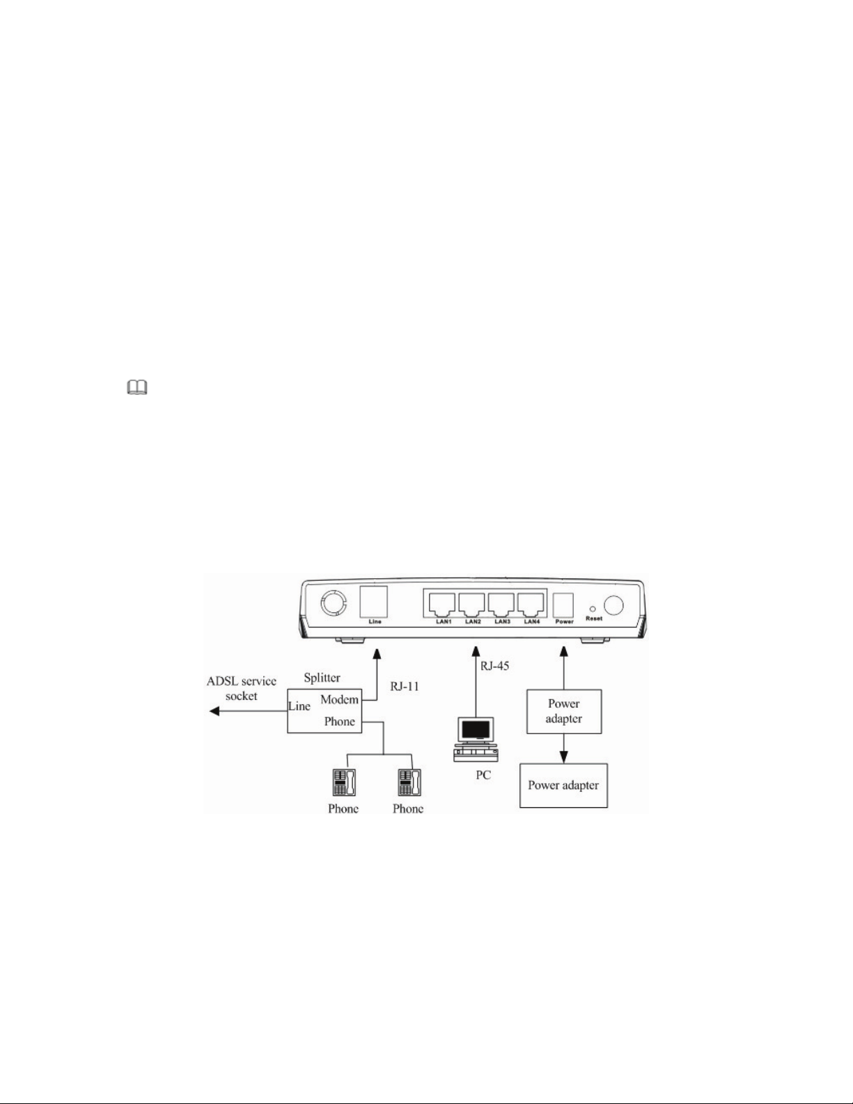
Connection 1
Figure 1 displays the application diagram for the connection of the router, PC, splitter and the telephone sets, when
no telephone set is placed before the splitter.
Figure 1 Connection Diagram (without connecting telephone sets before the splitter)
Connection 2
Figure 2 displays the application diagram for the connection of the router, PC, splitter and the telephone sets, when
a telephone set is placed before the splitter.
5
2 Hardware Installation
Step 1 Connect the Line interface of the device and the Modem interface of the splitter through a telephone cable.
Connect the phone to the Phone interface of the splitter through a cable. Connect the incoming line to the
Line interface of the splitter.
The splitter has three interfaces:
– Line: Connect to a wall phone jack (RJ-11 jack)
– Modem: Connect to the ADSL jack of the device
– Phone: Connect to a telephone set.
Step 2 Connect the LAN interface of the device to the network card of the PC through an Ethernet cable
(MDI/MDIX).
I
Page 9
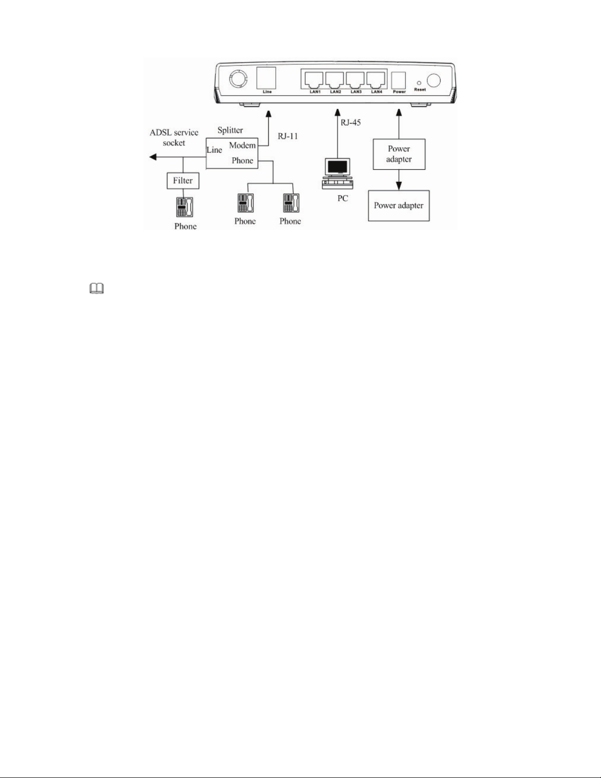
Figure 2 (with a telephone set before the splitter)
In the actual application, connection 1 is recommended.
I
Note:
When connection 2 is used, the filter must be installed close to the telephone lines. Do not use the splitter instead of the filter.
Installing a telephone directly before the splitter may lead to a failure of connection between the device and the
office central, or cannot access into the Internet, or slow the connection speed. If you really need to add a telephone
set before the splitter, you have to add a microfilter before connecting to a telephone set. Do not connect several
telephones before the splitter. Do not connect several telephones with the microfilter.
6
Page 10
If you log in as the super user, the page shown in the following figure appears. You can check, configure and
modify all the settings.
If you log in as a common user, you can check the status of the router, but can not change the most of the settings.
3.2 Setup Wizard
7
3 About the Web Configuration
This chapter describes how to configure the router by using the Web-based configuration utility.
3.1 How to Access the Router
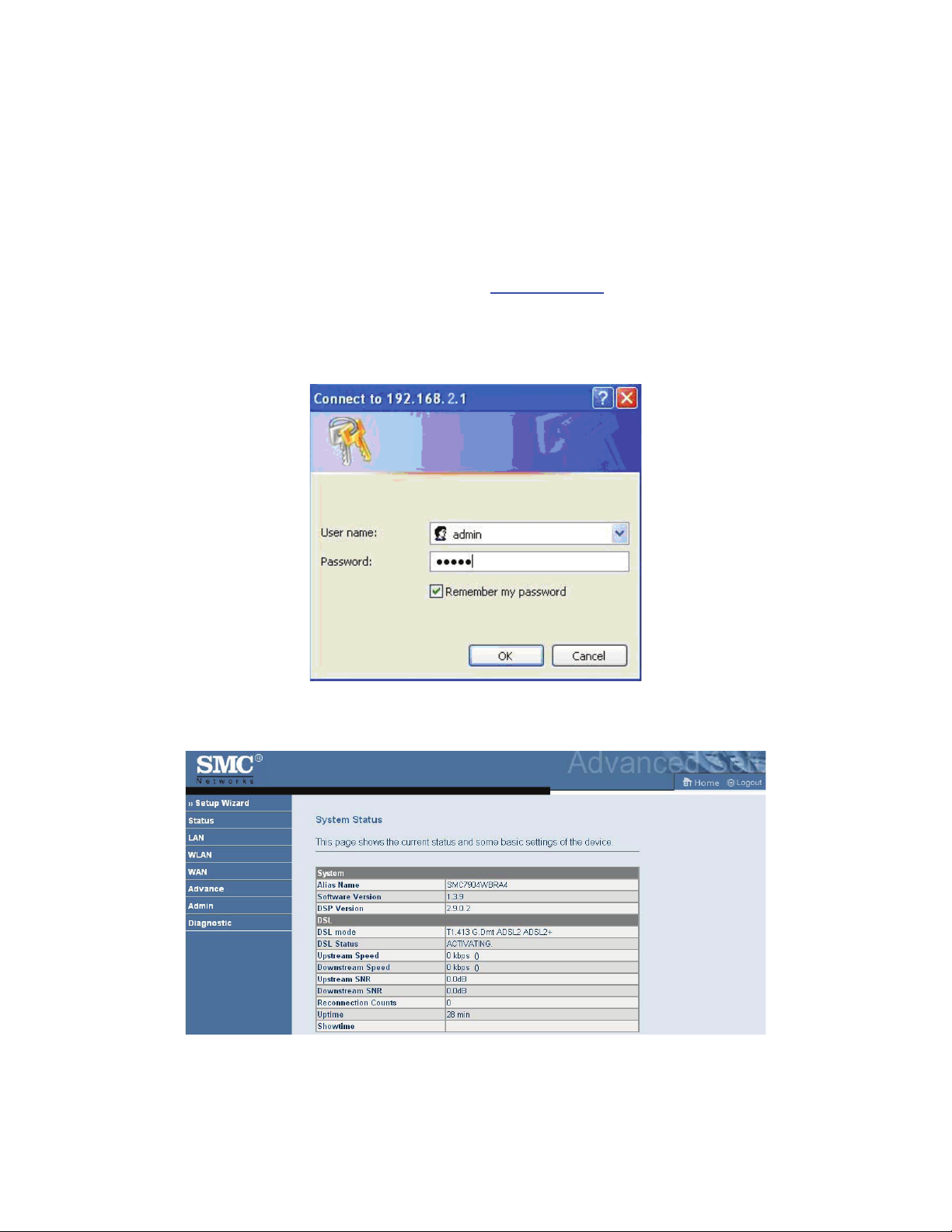
The following is the detailed description of accesing the router for the first time.
Step 1 Open the Internet Explorer (IE) browser and enter
Step 2 In the LOGIN page that is displayed, enter the username and password.
– The username and password of the super user are admin and smcadmin.
– The username and password of the common user are user and user.
http://192.168.2.1
.
Page 11
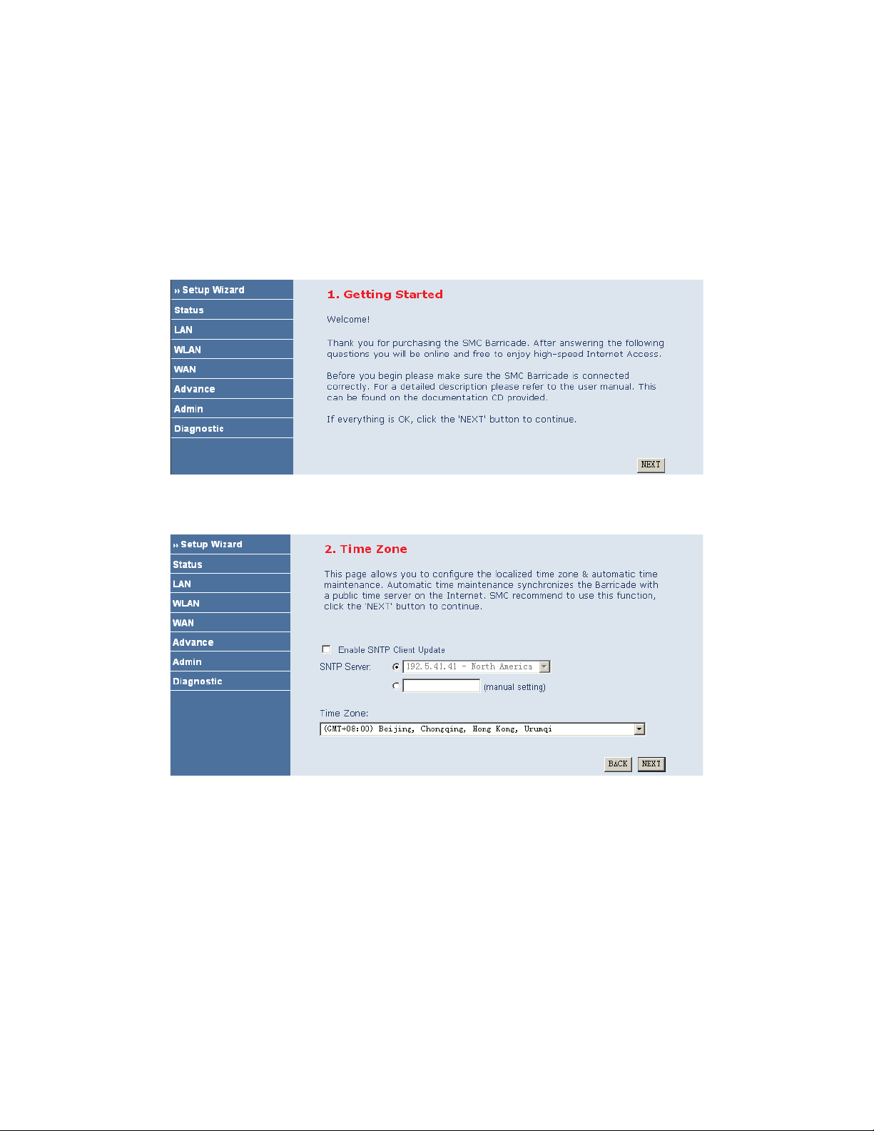
Click NEXT, the page shown in the following page appears. In this page, you can set the system time manually or
get the system time from the time server.
Click NEXT, the page shown in the following page appears. In this page, you can configure the wireless SSID,
wireless mode and channel number.
8
In the navigation bar, choose Setup Wizard. In the Setup Wizard page, you can configure the VPI/VCI number.
The Setup Wizard page guides fast and accurate configuration of the Internet connection and other important
parameters. The following sections describe these various configuration parameters. Whether you configure these
parameters or use the default ones, click NEXT to enable your Internet connection.
When subscribing to a broadband service, you should be aware of the method by which you are connected to the
Internet. Your physical WAN device can be either PPP, ADSL, or both. The technical information about the
properties of your Internet connection is provided by your Internet Service Provider (ISP). For example, your ISP
should inform you whether you are connected to the Internet using a static or dynamic IP address, and the protocol
that you use to communicate on the Internet.
Page 12
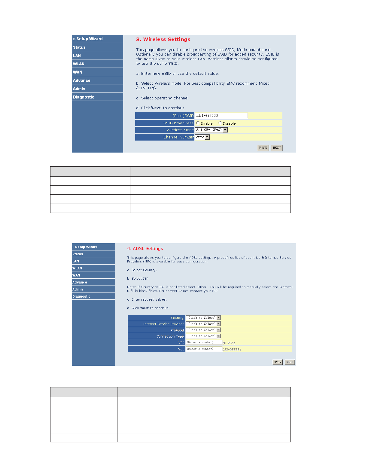
The following table describes the parameters of this page.
Field Description
(Root) SSID
SSID BroadCase
Wireless Mode
Channel Number
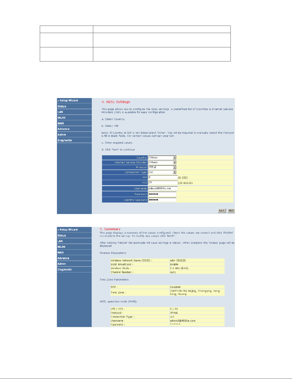
After configuring the wireless settings, click NEXT. The page shown in the following figure appears. In this page,
you can configure the ADSL settings.
The following table describes the parameters and buttons in this page.
Field
Description
Country Select the country in which you are in.
Internet Service Provider Select your ISP.
Protocol
Select the protocol. You can choose PPPoE, PPPoA, Dynamic IP, Static IP,
Bridge, or 1483 Route.
Connection Type Select the connection type provided by your ISP from the drop-down list box.
9
Page 13
After finishing the settings, click NEXT. The page shown in the following figure appears.
If you ensure the configuration is correct, click FINISH. Then the configuration takes effect. You can check the
configuration in the WAN page.
10
You can choose LLC or VC-Mux.
VPI
VCI
The virtual path between two points in an ATM network, and its valid value is
from 0 to 255.
The virtual channel between two points in an ATM network, ranging from 32 to
65535 (0 to 31 is reserved for local management of ATM traffic).
Before you configure the protocol, you must select the country in which you are in and your ISP.
PPPoE
If the uplink equipment supports the PPPoE protocol, you can set the device to initiate the PPPoE dialup.
Page 14
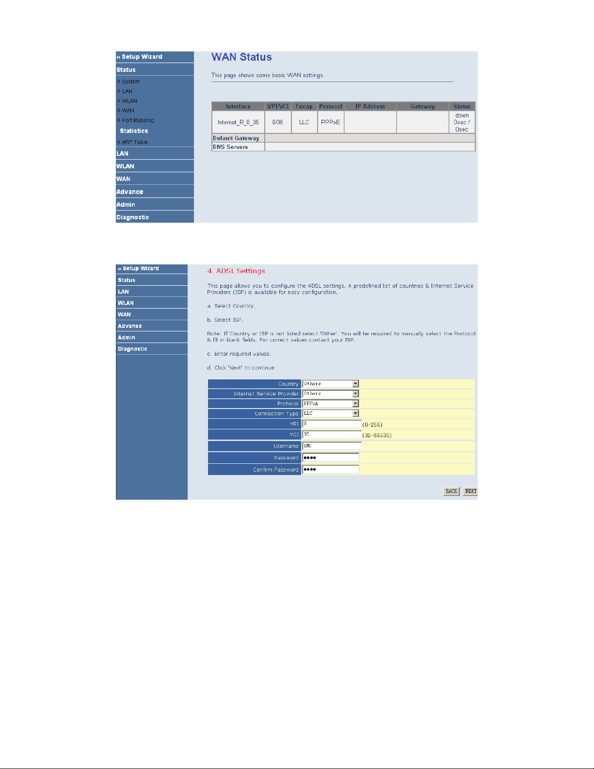
PPPoA
If the uplink equipment supports the PPPoA encapsulation, you can set the device to initiate the PPPoA dialup.
After finishing the settings, click NEXT. The page shown in the following figure appears.
11
Page 15
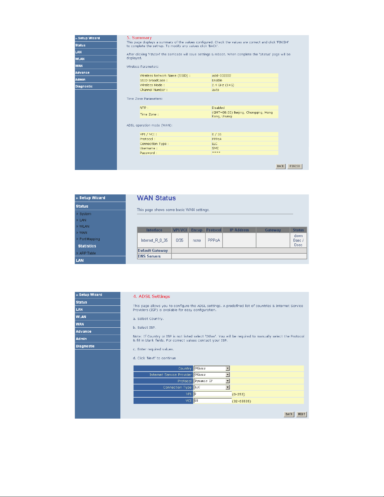
If you ensure the configuration is correct, click FINISH. Then the configuration takes effect. You can check the
configuration in the WAN page.
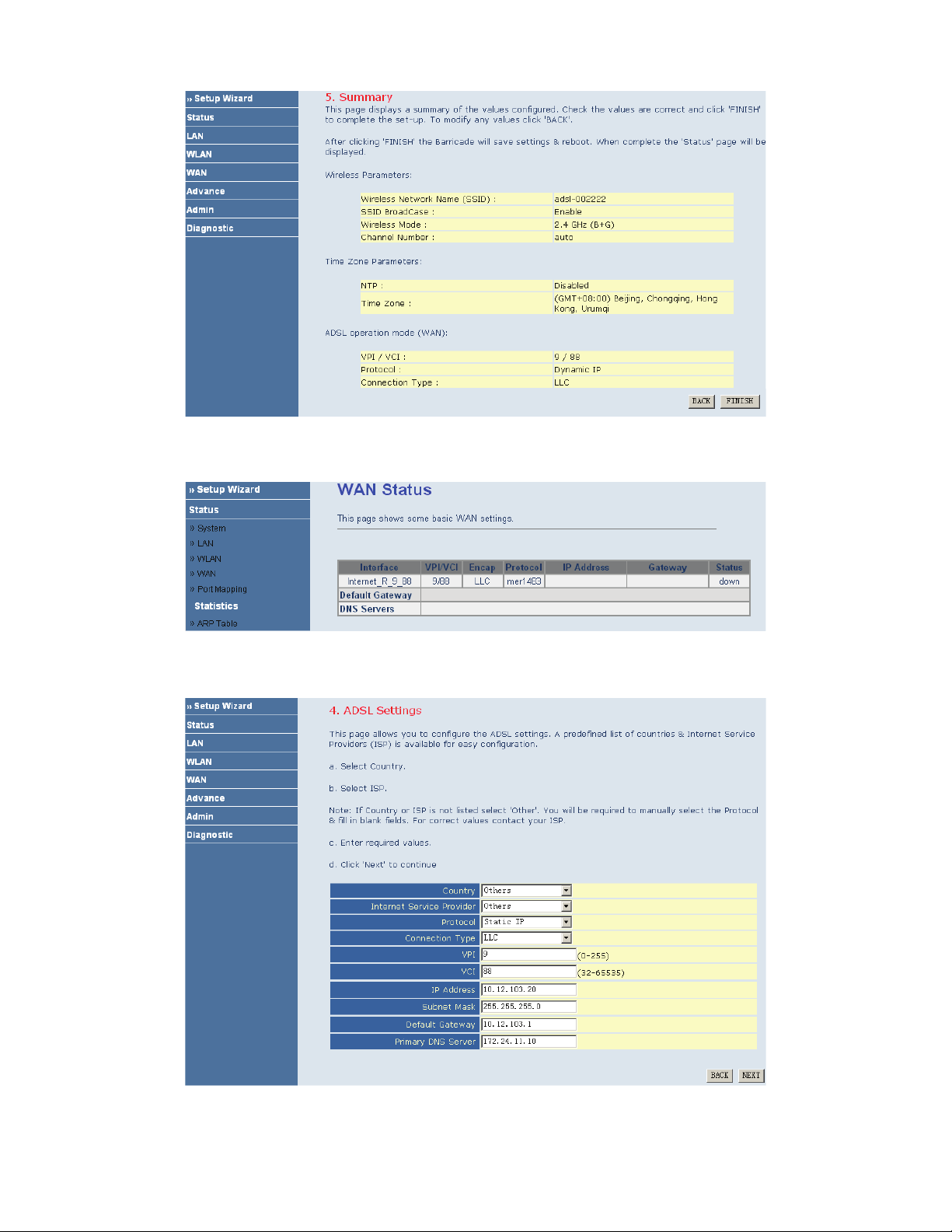
Dynamic IP
If the uplink equipment supports the Dynamic IP protocol, you can set the device to initiate the dynamic IP dialup.
After finishing the settings, click NEXT. The page shown in the following figure appears.
12
Page 16
If you ensure the configuration is correct, click FINISH. Then the configuration takes effect. You can check the
configuration in the WAN page.
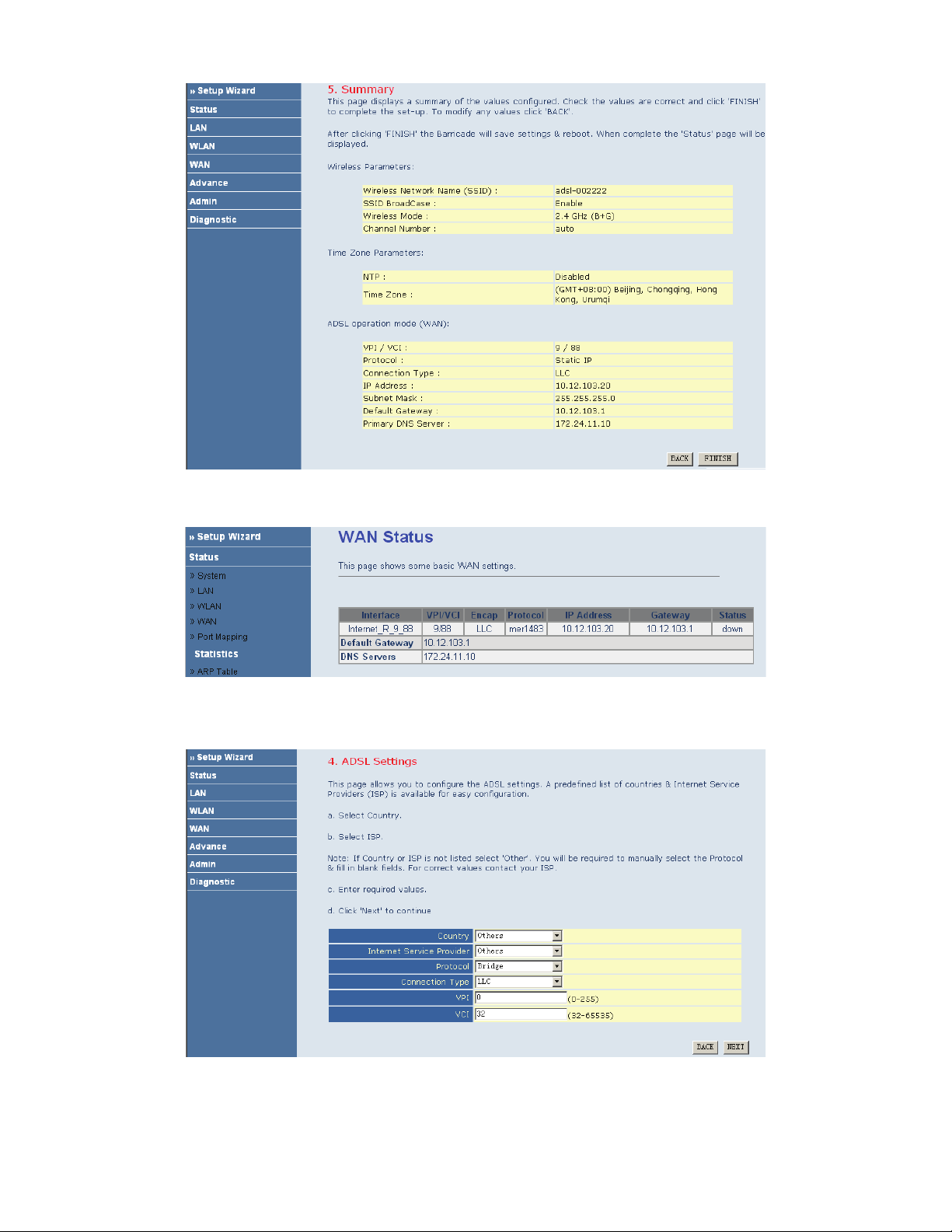
Static IP
If the uplink equipment supports the Static IP protocol, you can set the device to initiate the static IP dialup.
After finishing the settings, click NEXT. The page shown in the following figure appears.
13
Page 17
If you ensure the configuration is correct, click FINISH. Then the configuration takes effect. You can check the
configuration in the WAN page.
Bridge
If the uplink equipment supports the Bridge protocol, you can set the device to initiate the bridge dialup.
After finishing the settings, click NEXT. The page shown in the following figure appears.
14
Page 18
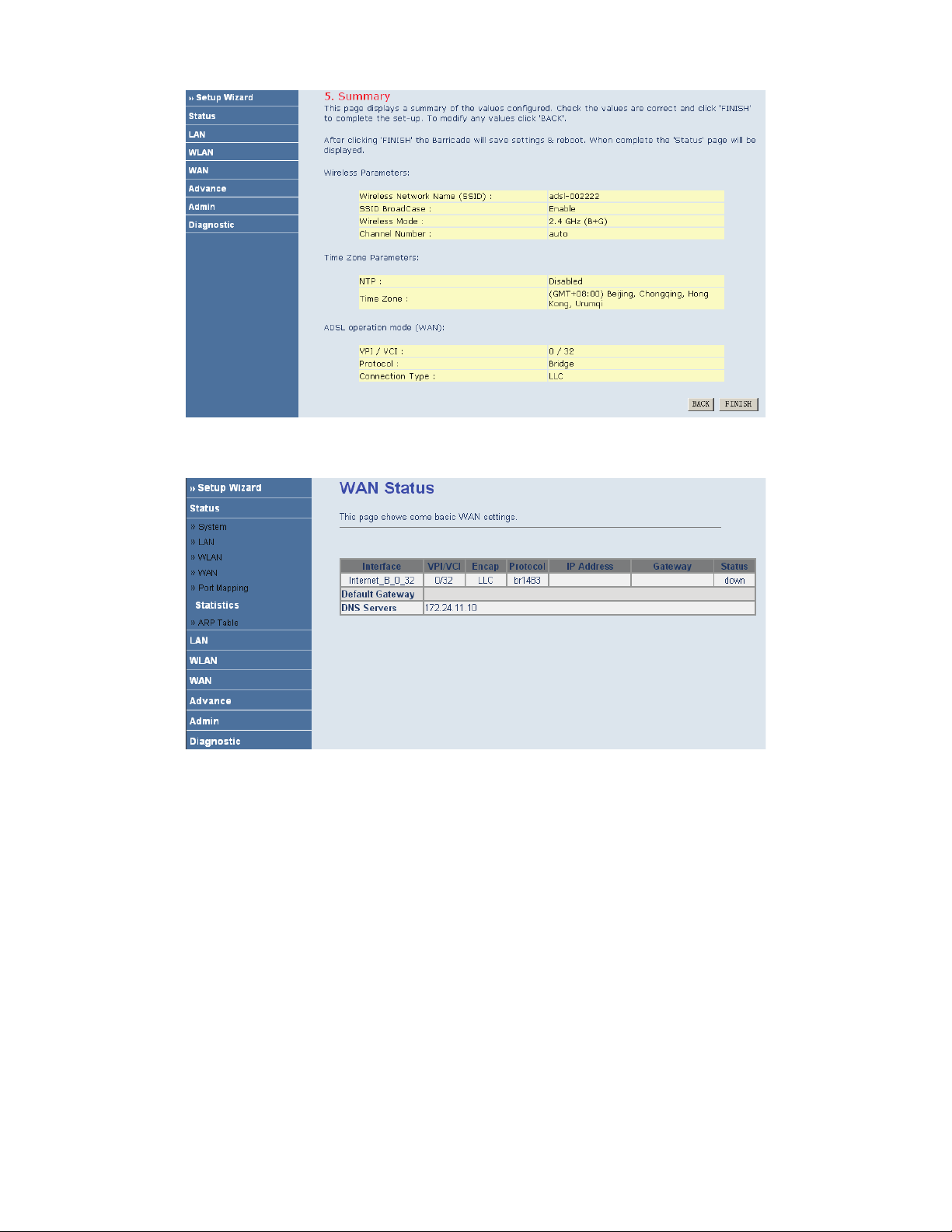
If you ensure the configuration is correct, click FINISH. Then the configuration takes effect. You can check the
configuration in the WAN page.
1483 Route
If the uplink equipment supports the 1483 Route protocol, you can set the device to initiate the 1483 route dialup.
15
Page 19
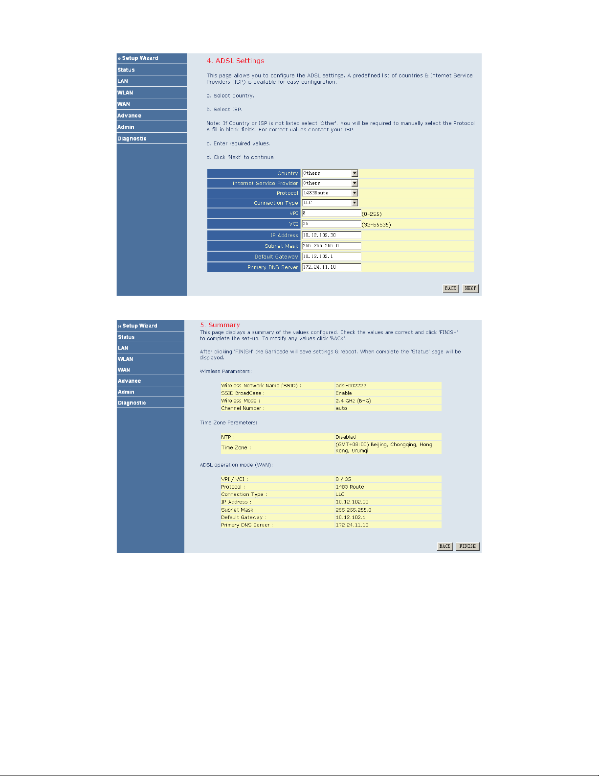
After finishing the settings, click NEXT. The page shown in the following figure appears.
If you ensure the configuration is correct, click FINISH. Then the configuration takes effect. You can check the
configuration in the WAN page.
16
Page 20
I
Note:
After you select the country in which you are in and the correct ISP, the ADSL settings, such as protocol, connection type, VPI, and VCI
appears. It is recommended to use the default values.
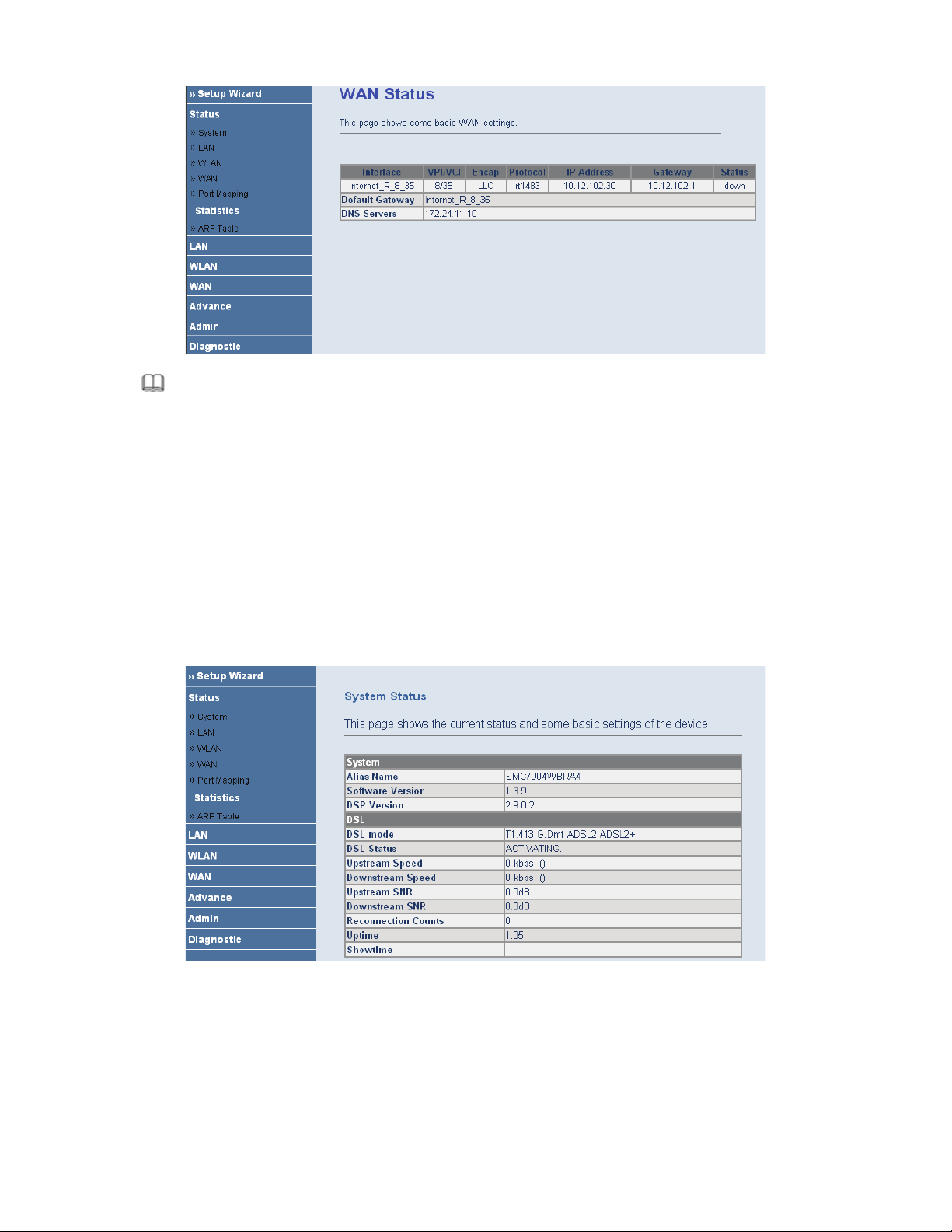
3.3 Status
In the navigation bar, choose Status. In the Status page that is displayed contains: System, LAN, WLAN, WAN,
Port Mapping, Statistic, and ARP Table.
3.3.1 System
Choose Status > System. The page that is displayed shows the current status and some basic settings of the router,
such as software version, DSL mode, upstream speed, downstream speed, and uptime.
3.3.2 LAN
Choose Status > LAN. The page that is displayed shows some basic LAN settings of the router. In the LAN page,
you can view the LAN IP address, DHCP server status, MAC address, and DHCP client table. If you want to
configure the LAN network, refer to Chapter 3.4.1 LAN Settings.
17
Page 21
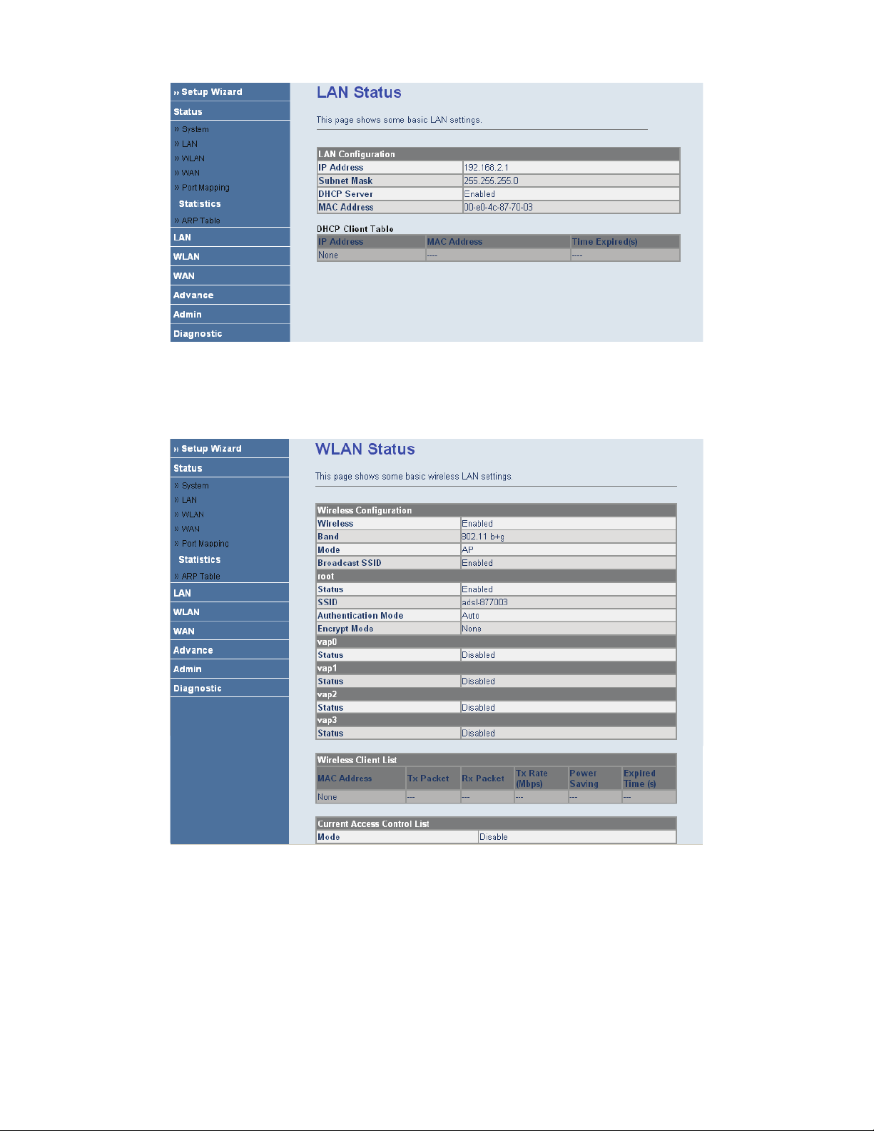
3.3.3 WLAN
Choose Status > WLAN. The page that is displayed shows some basic wirless LAN settings of the router.
3.3.4 WAN
Choose Status > WAN. In the WAN page, you can view basic status of WAN, default gateway, DNS server. If you
want to configure the WAN network, refer to the chapter3.6.1 WAN Interface.
18
Page 22
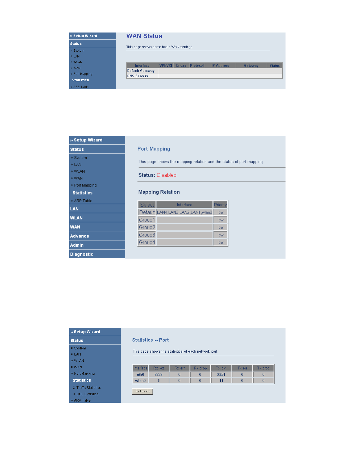
3.3.5 Port Mapping
Choose Status > Port Mapping. In the Port Mapping page, you can view the mapping relation and the status of
port mapping.
3.3.6 Statistic
Choose Status > Statistic. The Statistic page that is displayed contains Traffic Statistic and DSL Statistic.
3.3.6.1 Traffic Statistic
Choose Traffic Statistic in the left pane. The page shown in the following figure appears. In this page, you can
view the statistics of each network port.
19
Page 23

3.3.7 ARP Table
Choose Status > ARP Table. In the ARP Table page, you can view the table which shows a list of learned MAC
addresses.
3.4 LAN
In the navigation bar, choose LAN. The LAN page that is displayed contains LAN Settings and DHCP Settings.
In this page, you can use the LAN configuration to define an IP address for the router and configure the DHCP
server.
20
3.3.6.2 DSL Statistic
Choose DSL Statistic in the left pane. The page shown in the following figure appears. In this page, you can view
the ADSL line statistics, downstream rate, upstream rate, and other information.
Page 24

The following table describes the parameters and buttons of this page.
Field Description
IP Address
Enter the IP of LAN interface. It is recommended to use an address from a
block that is reserved for private use. This address block is 192.168.2.2-
192.168.2.254.
Subnet Mask
Enter the subnet mask of LAN interface. The range of subnet mask is from
255.255.0.0-255.255.255.254.
Secondary IP
Select it to enable the secondary LAN IP. The two LAN IP address must be in
the different network.
Apply Changes Save the settings of this page.
3.4.2 DHCP Settings
Choose LAN > DHCP Settings.
Dynamic Host Configuration Protocol (DHCP) allows the individual PC to obain the TCP/IP configuration from
the centralized DHCP server. You can configure this router as a DHCP server or disable it. The DHCP server can
assign IP address, IP default gateway and DNS server to DHCP clients. This router can also act as a surrogate
DHCP server (DHCP proxy) where it relays IP address assignment from an actual real DHCP server to clients. You
can enable or disable DHCP server or DHCP proxy.
Select Disable in the DHCP Server Setup page. The page shown in the following figure appears.
21
3.4.1 LAN Settings
Choose LAN > LAN Settings. In the LAN Settings page, you can configure the LAN network. In this page, you
can change IP address of the router. The default IP address is 192.168.2.1. This is the private IP address of the
router. This is the address under which the router can be reached in the local network. It can be freely assigned from
the block of available addresses.
Page 25

Select DHCP Proxy in the DHCP Server Setup page. The page shown in the following figure appears.
The following table describes the parameters of this page.
Field Description
DHCP Proxy
Select it, the router acts a surrogate DHCP Server and relays the DHCP requests and
reponses between the remote server and the client.
DHCP Server Address Enter the IP address of the actual, remote DHCP server.
Select DHCP Server in the DHCP Server Setup page. The page shown in the following figure appears.
22
Page 26

Field Description
DHCP Server
If set to DHCP Server, the router can assign IP addresses, IP default gateway and
DNS Servers to Windows95, Windows NT and other systems that support the DHCP
client.
IP Pool Range It specifies the first and the last of contiguous IP address of the IP address pool.
Show Client
Click it, the Active DHCP Client Table page appears. It shows the assigned IP
address of the clients.
Max Lease Time
The lease time determines the period that the PCs retain the assigned IP addresses
before the IP addresses change.
Domain Name
Enter the domain name if you know. If you leave this blank, the domain name
obtained by DHCP from the ISP is used. You must enter host name (system name) on
each individual PC. The domain name can be assigned from the router through the
DHCP server.
Gateway Address Enter the IP default gateway of the IP address pool.
MAC-based Assignment
Click it, the Static IP Assignment Table page appears. It allows you assign IP
addresses on the LAN to specify individual PCs based on their MAC address.
Click Show Client in the DHCP Server Setup page. The page shown in the following figure appears. In this page,
you can view the IP address assigned to each DHCP client.
The following table describes the parameters and buttons in this page.
Field
Description
IP Address It displays the IP address relative to the MAC address.
MAC Address
It displays the MAC address of the PC.
Each Ethernet device has a unique MAC address. The MAC address is assigned
at the factory and it consists of six pairs of hexadecimal character, for example,
00-A0-C5-00-02-12.
Time Expired (s) It shows the lease time. The lease time determines the period that the PCs retain
23
The following table describes the parameters in this page.
Page 27

Description
Field
the assigned IP addresses before the IP addresses change.
Refresh Refresh the page.
Close Close the page.
Click MAC-based Assignment in the DHCP Server Setup page. The page shown in the following figure appears.
In this page, you can assign the IP addresses on the LAN to the specific individual PCs based on their MAC
address.
The following table describes the parameters and buttons of this page.
Field Description
Host MAC Address Enter the MAC address of a PC on the LAN.
Assigned IP Address It specifies the IP address of the IP address pool.
Assign IP After entering the host MAC address and assigned IP address, click it. A row will
be added in the MAC-base assignment table.
Modify Assigned IP Select a row in the MAC-base assignment table. The MAC address and IP
address appear. After modifying the MAC address and IP address, click it to save
the settings.
Delete Assigned IP Select a row in the MAC-base assignment table, then click it, this row is deleted.
Close Close the page.
MAC-based Assignment Table It shows the assigned IP address based on the MAC address.
3.5 WLAN
In the navigation bar, choose WLAN. The WLAN page that is displayed contains Basic Settings, Security,
Advance Settings, Access Control, and WDS Settings. This page introduces the wireless LAN and some basic
configurations. Wireless LANs can be as simple as two computers with wireless LAN cards communicating in a
pear-to-pear network or as complex as a number of computers with wireless LAN cards communicating through
access points which bridge network traffic to wired LAN.
24
Page 28

The following table describes the parameters and buttons of this page.
Field Description
Disable Wireless LAN
Interface
By default, the wireless LAN is enabled. Select it to disable the wireless LAN.
(Root) SSID
The service set identification (SSID) is a unique name to identify the router in the
wireless LAN. Wireless stations associating to the router must have the same
SSID. Enter a desciptive name.
Set VSSID
Click it, the Virtual SSID Setting page appears. In this page, you can enable 4
VSSIDs at most.
SSID You can enable or disnable SSID.
Country/Area Select the region which you are in.
Channel Number
A channel is the radio frequency used by 802.11b/g wireless device. Channels
available depend on your geographical area. You may have a choice of channels
(for your region) and you should use a different channel from an adjacent AP to
reduce the interference. Interference and degrading performance occurs when
radio signal from diffirent APs overlap.
Select a channel from the drop-down list box.
Apply Changes Save the settings of this page.
Click Set VSSID, the page shown in the following figure appears.
25
3.5.1 Basic Settings
Choose WLAN > Basic Settings. The page shown in the following figure appears. In this page, you can configure
the parameters for wireless LAN clients that may connect to your access point.
Page 29

The following table describes the parameters and buttons of this page.
Field Description
Vap
SSID The service set identification (SSID) is a unique name to identify the router in
the wireless LAN
Auth Type
You can choose Open System, Shared Key, or Auto.
If you select Open System, you can
If you select Shared Key, you can
If you select Auto, you can
Apply Chnages Save the settings of this page.
Undo Refresh this page.
3.5.2 Security
Choose WLAN > Security. The page shown in the following figure appears. Wireless security is vital to your
network. It protects the wireless communication among the wireless stations, access points and the wireless
network.
26
Page 30

The following table describes the parameters and buttons of this page.
Field Description
SSID Type Select the SSID.
Encryption
You can choose None, WEP, WPA (TKIP), WPA2 (AES), or WPA2 Mixed.
Wired equivalent privacy (WEP) entrypts data frames before transmitting over
the wireless network.
Wi-Fi protected access (WPE) is a subset of the IEEE802.11i security
specification draft. Key differences between WPA and WEP are user
authentication and improved data encryption.
Set WEP Key
It is available when you set to WEP. Click it, the Wireless Wep Key Setup page
appears.
Authentication RADIUS
Server
RADIUS is based on a client-server model that supports authentication,
authorization and accounting. The access point is client and the server is
RADIUS server. RADIUS is a simple package exchange in which your router
acts as a message relay between the wireless station and the network RADIUS
server.
Port
The default port of the RADIUS server for authentication is 1812. You need not
change this value unless your network administrator instructs you to do so with
additional information.
IP Address Enter the IP address of the RADIUS server.
Password
Enter a password as the key to be shared between the external authentication
server and the access point. The key is not send over the network. This key must
be the same on the external authentication server and your router.
Apply Changes Save the the changes of this page.
Click Set WEP Key, the page shown in the following figure appears.
27
Page 31

The following table describes the parameters and buttons of this page.
Field Description
SSID TYPE Select the SSID.
Key Length Select 64-bit or 128-bit to use data encryption.
Key Format
If you choose 64-bit, you can choose ASCII (5 characters) or Hex (10
characters).
If you choose 128-bit, you can choose ASCII (13 characters) or Hex (26
characters).
Default Tx Key Select the default encryption key.
Encryption Key 1 to 4
The Encryption keys are used to encrypt the data. Both router and wireless stations
must use the same encryption key for data transmission.
If you choose 64-bit and ASCII (5 characters), enter any 5 ASCII characters.
If you choose 64-bit and Hex (10 characters), enter any 10 hexadecimal
characters.
If you choose 128-bit and ASCII (13 characters), enter any 13 ASCII
characters.
If you choose 128-bit and Hex (26 characters), enter any 26 hexadecimal
characters.
Apply Changes Save the changes of this page.
Close Close this page.
Undo Refresh this page.
3.5.3 Advance Settings
Choose WLAN > Advance Settings. The page shown in the following figure appears. These settings are only for
more technically advanced users who have a sufficient knowledge about wireless LAN. These settings should not
be changed unless you know the effect of the changes on your AP.
28
Page 32

The following table describes the parameters of this page.
Field Description
Fragment Threshold
This is the maximum data fragment size (between 256 and 2346bytes) that can be sent
in the wireless network before the router fragments the packet into smaller data frames.
RTS Threshold
Request to send (RTS) is designed to prevent collisions due to hidden node. A RTS
defines the biggest size data frame you can send before a RTS handshake invoked. The
RTS threshold value is between 0 and 2347.
If the RTS threshold value is greater than the fragment threshold value, the RTS
hankshake do not occur. Because the data frames are fragmented before they reach the
RTS size.
3.5.4 Access Control
Choose WLAN > Access Control. The page shown in the following figure appears. In this page, you can configure
the wireless access control.
29
Page 33

The following table describes the parameters and buttons of this page.
Field Description
Select Access Control
Mode
You can choose Disable, Allow Listed, or Deny Listed.
Select Allow Listed, only the clients whose MAC address is listed can access the
router.
Select Deny Listed, the clients whose MAC address is listed are denied to access
the router.
Apply Changes Save the changes of selecting the access control mode.
MAC Addr
Enter the MAC address of the wireless station that are allowed or denied access to
your router in this address field.
Apply Changes Save the changes of MAC Addr.
Reset Refresh the MAC address.
Current Access Control
List
The MAC address in this table is allowed or denied to access to the router.
Delete Delete the row you select in the current access control list.
Delete All Delete all rows in the current access control list.
Reset Refresh the current access control list.
3.5.5 WDS Settings
Choose WLAN > WDS Settings. The page shown in the following figure appears.
30
Page 34

The following table describes the fields of this screen.
Label Description
Enable WDS Select it to enable the WDS function. Otherwise, you can not
configure the settings of this page.
MAC Addr Enter the MAC address (in XX-XX-XX-XX-XX-XX format) of the
AP.
Comment Enter the comment to describe the AP of the MAC address.
Apply Change
Click it to add the MAC Addr with the Comment to Current WDS
AP List.
Reset
Click it to refresh the MAC Addr and Comment.
Current WDS AP List This table shows all APs of the WDS.
Delete
Click it to delete the row of the Current WDS AP List.
Delete All
Click it to delete all rows of the Current WDS AP List.
3.6 WAN
In the navigation bar, choose WAN. The WAN page that is displayed contains WAN Interface and ADSL Settings.
3.6.1 WAN Interface
Choose WAN > WAN Interface. The page shown in the following figure appears. In this page, you can configure
WAN interface of your router.
31
Page 35

The following table describes the parameters of this page.
Field Description
Current ATM VC Table
This table shows the existed PVCs. It shows the Interface name, channel mode,
VPI/VCI, encapsulation mode, local IP address, remote IP address and other
information. The maximum item of this table is eight.
Click it, the IP Interface-Modify page appears. You can modify the PVCs’
parameters.
VPI
The virtual path between two points in an ATM network, ranging from 0 to
255.
VCI
The virtual channel between two points in an ATM network, ranging from 32
to 65535 (1 to 31 are reserved for known protocols)
Encapsulation
You can choose LLC and VC-Mux.
Channel Mode
You can choose 1483 Bridged, 1483 MER, PPPoE, PPPoA, or 1483 Routed.
Admin Status Select Disable, this PVC is unusable.
Enable NAPT
Select it to enable the NAPT function of the router. If you do not select it and
you want to access the Internet normally, you must add a router on the uplink
equipment. Otherwise, the access to the Internet fails. Normally, it is required
to enable NAPT.
Login Name The correct user name that your ISP has provided to you.
Password The correct password that your ISP has provided to you.
Connection Type
You can choose Continuous, Connect on Demand, or Manual.
Idle Time(min)
If select connect on demand, you need to enter the idle timeout time. Within
the preset minutes, if the router does not detect the flow of the user
continuously, the router automatically disconnects the PPPoE connection.
WAN IP Settings
Type
You can choose Fixed IP or Use DHCP.
If select Fixed IP, you should enter the local IP address, remote IP address
and subnet mask.
32
Page 36

Field Description
If select Use DHCP, the router is a DHCP client, the WAN IP address is
assigned by the remote DHCP server.
Local IP Address It is the IP address of WAN interface which is provided by your ISP.
Remote IP Address This is the gateway IP address which is provided by your ISP.
Subnet Mask It is the subnet mask of the local IP address.
Unnumbered Select this checkbox to enable IP Unnumbered function.
Default Route
Add
After configuring the parameters of this page, click it to add a new PVC into
the current ATM VC table.
Modify
Select a PVC in the current ATM VC table, then modify the parameters of this
PVC. After finishing, click it to apply the change of this PVC.
Delete Select a PVC in the current ATM VC table, then click it to delete this PVC.
Undo Click it to refresh the page.
ATM Settings
Click it, the ATM Settngs page appears. You can configure the parameters of
the ATM for the router, including Qos type, PCR, CDVT, SCR and MBS.
Click
in the 1483 Routed mode. The page shown in the following figure appears. In this page, you can
configure parameters of this 1480 routed PVC.
Click ATM Setting in the WAN Interface page. The page shown in the following figure appears. In this page, you
can configure the parameters of the ATM for your ADSL router, including QoS type, PCR, CDVT, SCR and MBS.
33
Page 37

The following table describes the parameters and buttons of this page.
Field Description
3.6.2 ADSL Settings
Choose WAN > ADSL Settings. The page shown in the following figure appears. In this pae, you can select the
DSL modulation. Mostly, you need to remain this factory default settings. The router supports these modulations:
G.lite, G.Dmt, T1.413, ADSL2, ADSL2+, AnnexL, and AnnexM. The router negotiates the modulation modes
with the DSLAM.
34
Page 38

3.7 Advance
In the navigation bar, choose Advance. The Advance page that is displayed contains DNS, Firewall, Virtual
Server, Routing, IP QOS, Anti-DOs, Port Mapping, and Other.
3.7.1 DNS
Choose Advance > DNS. The DNS page that is displayed contains DNS Server and DDNS.
3.7.1.1 DNS Server
Choose DNS Server in the left pane. The page shown in the following figure appears.
Domain name system (DNS) is an Internet service that translates the domain name into IP address. Because the
domain name is alphabetic, it is easier to remember. The Internet, however, is based on IP addresses. Every time
you use a domain name, a DNS service translates the name into the corresponding IP address. For example, the
domain name www.example.com might translate to 198.105.232.4. The DNS system has its own network. If one
DNS server does not know how to translate a particular domain name, it asks another one, and so on, until the
correct IP address is returned.
35
Page 39

The following table describes the parameters and buttons of this page.
Field Description
Obtain DNS
Automatically
Select it, the router accepts the first received DNS assignment from one of the PPPoA,
PPPoE or MER enabled PVC(s) during the connection establishment.
Set DNS Manually Select it, enter the primary and optional secondary DNS server IP addresses.
Apply Changes Save the settings of this page.
Reset Selected Refresh this page.
3.7.1.2 DDNS
Choose DDNS in the left pane. The page shown in the following figure appears.
The following table describes the parameters and buttons of this page.
Field Description
36
Page 40

Click Apply Changes to save the settings of this page.
Click Add Rule to add a new rule of the IP/Port filter.
The following table describes the parameters and buttons of this page.
37
3.7.2 Firewall
Choose Advance > Firewall. The Firewall page that is displayed contains IP/Port Fileter, MAC Filter, and URL
Blocking.
3.7.2.1 IP/Port Filter
Choose IP/Port Filter in the left pane. The page shown in the following figure appears. Entries in this table are
used to restrict certain types of data packets through the gateway. These filters are helpful in securing or restricting
your local network.
Page 41

Field Description
3.7.2.2 MAC Filter
Choose MAC Filter in the left pane. The page shown in the following figure appears. Entries in this table are used
to restrict certain types of data packets from your local network to Internet through the gateway. These filters are
helpful in securing or restricting your local network.
Click Apply Changes to save the settings of this page.
Click Add Rule to add a new rule of the MAC filter.
The following table describes the parameters and buttons of this page.
Field Description
38
Page 42

Field Description
3.7.2.3 URL Blocking
Choose URL Blocking in the left pane. The page shown in the following figure appears. This page is used to block
a fully qualified domain name (FQDN), such as tw.yahoo.comand and filtered keyword. You can add or delete
FQDN and filtered keyword.
The following table describes the parameters and buttons of this page.
Field Description
3.7.3 Virtual Server
Choose Advance > Virtual Server. The page shown in the following figure appears. The page that is displayed
contains Services and DMZ Settings.
3.7.3.1 Services
Choose Services in the left pane. The page shown in the following figure appears. This page is used to enable the
servers in the local network.
39
Page 43

Click Add to add a virtual server. The page shown in the following figure appears.
The following table describes the parameters and buttons of this page.
Field Description
3.7.3.2 DMZ Settings
Choose DMZ Settings in the left pane. The page shown in the following figure appears. A demilitarized zone is
used to provide Internet services without sacrificing unauthorized access to its local private network. Typically, the
DMZ host contains devices accessible to Internet traffic, such as web (HTTP) servers, FTP servers, SMTP (e-mail)
servers and DNS servers.
Step 1 Select Enable DMZ to enable this function.
Step 2 Enter an IP address of the DMZ host.
Step 3 Click Apply Changes to save the settings of this page.
40
Page 44

3.7.4 Routing
Choose Advance > Routing. The page shown in the following figure appears. The page that is displayed contains
Static Route and RIP.
3.7.4.1 Static Route
Choose Static Route in the left pane. The page shown in the following figure appears. In this page, you can
configure the routing information. You can add or delete IP routes.
The following table describes the parameters and buttons of this page.
Field Description
Click Show Routes. The table shown in the following figure appears. The table shows a list of destination routes
commonly accessed by your network.
41
Page 45

3.7.4.2 RIP
Choose RIP in the left pane. The page shown in the following figure appears. If you are using this device as a
RIP-enabled router to communicate with others who is using the Routing Information Protocol (RIP), enable the
RIP. This page is used to select the interfaces on your devices that use RIP, and the version of the protocol used.
The following table describes the parameters and buttons of this page.
Field Description
42
Page 46

Click Add Rule, the page shown in the following figure appears.
The following table describes the parameters and buttons of this page.
Field Description
43
3.7.5 IP QoS
Choose Advance > IP QOS. The page shown in the following figure appears. Entries in this table are used to
assign the precedence for each incoming packet based on physical LAN port, TCP/UDP port number, and
source/destination IP address/subnet masks.
Page 47

Click Apply Changes to save the settings of this page.
3.7.7 Port Mapping
Choose Advance > Port Mapping. The page shown in the following figure appears. In this page, you can bind the
WAN interface and the LAN interface to the same group.
The procedure for manipulate a mapping group is as follows:
Step 1 Select Enable to enable this function.
Step 2 Select a group from the table.
Step 3 Select interfaces from the WAN and LAN interface list and add them to the grouped interface list using the
arrow buttons to manipulate the required mapping of the ports.
Step 4 Click Apply Changes to save the changes.
44
3.7.6 Anti-dos
Choose Advance > Anti-Dos. The page shown in the following figure appears. Denial-of-service attack (DoS
Attack) is a type of attack on a network that is designed to bring the network to its knees by flooding it with useless
traffic. In this page, you can prevent DoS attacks.
Page 48

3.7.8 Other
Choose Advance > Other. In the Other page that is displayed contains IGMP Proxy, UPNP, Bridge, and IP
PassThrough.
3.7.8.1 IGMP Proxy
Choose IGMP Proxy in the left pane. The page shown in the following figure appears. IGMP proxy enables the
system to issue IGMP host messages on behalf of hosts that the system discovered through standard IGMP
interfaces. The system acts as a proxy for its hosts afteryou enable it.
45
Page 49

Click Apply Changes to save the settings of this page.
3.7.8.2 UPNP
Choose UPNP in the left pane. The page shown in the following figure appears. This page is used to configure
UPnP. The system acts as a daemon after you enable it.
Click Apply Changes to save the settings of this page.
3.7.8.3 Bridge
Choose Bridge in the left pane. The page shown in the following figure appears. This page is used to configure the
bridge parameters. In this page, you can change the settings or view some information in the bridge mode and its
attached ports.
46
Page 50

The following table describes the parameters and buttons of this page.
Field Description
Click Show MACs. The page shown in the following figure appears. This table shows a list of learned MAC
addresses for this bridge.
3.7.8.4 IP PassThrough
Choose IP Pass Through in the left pane. The page shown in the following figure appears. IP passthrough is also
known as ZIPB or IP extension. In this page, you can enable and configure IP passthrough.
47
Page 51

3.8 Admin
In the navigation bar, choose Admin. The Admin page that is displayed contains Remote Access, Commit/Reboot,
Password, Backup/Restore, Upgrade Fireware, Time Zone, System Log, SNMP, TR069, ACL, and Logout.
3.8.1 Remote Access
Choose Admin > Remote Access. The page shown in the following figure appears. You can enable or disable the
services which are used by the remote host. For example, if TELNET service is enabled and the port is 23, the
remote host can access this router by telnet through the port 23.
3.8.2 Commit/Reboot
Choose Admin > Commit/Reboot. The page shown in the following figure appears. In this page, you can set the
router reset to the default settings or set the router to commit the current settings.
48
Page 52

The following table describes the parameters of this page.
Field Description
reset to default settings Select it to reset the router to the default settings.
commit current settings Select it to save the current settings and reboot the router.
Reboot Reboot the router.
3.8.3 Password
Choose Admin > Password. The page shown in the following figure appears. In this page, you can change the
password of the user, including admin and user. By default, the super user name and password are admin and
smcadmin. The common user name and password are user and user.
The following table describes the parameters of this page.
Field Description
User Name
You can choose admin or user.
Old Password After selecting the user name, enter the corresponding old password of the
49
Page 53

Field Description
user.
New Password Enter the password to which you want to change the old password.
Confirmed Password Enter the new password again.
3.8.4 Backup/Restore
Choose Admin > Backup/Restore. The page shown in the following figure appears. In this page, you can backup
the current settings to a file and restore the settings from the file which was saved previously.
Note:
Do not turn off your router or press the Reset button while these procedures are in progress.
The following table describes the parameters and buttons of this page.
Field Description
Save Settings to File
Click it and select the path. Then you can save the configuration file of the
router.
Load Settings from File
Click Browse to select the configuration file.
Upload
Select the configuration file of the router. Click Upload to begin restoring the
router configuration.
3.8.5 Upgrade Fireware
Choose Admin > Upgrade Firmware. The page shown in the following figure appears. In this page, you can
upgrade the firmware of the router.
I
Note:
Do not turn off your router or press the Reset button while this procedure is in progress.
50
Page 54

The following table describes the parameters and buttons of this page.
Field Description
Select File
Click Browse to select the firmware file.
Upload
Select the firmware file and click Upload to begin upgrading the firmware.
Reset Click it to begin selecting the firmware file.
3.8.6 Time Zone
Choose Admin > Time Zone. The page shown in the following figure appears. In this page, you can set the system
time manually or get the system time from the time server.
The following table describes the parameters of this page.
Field Description
51
Page 55

The following table describes the parameters and buttons of this page.
Field Description
System Log You can enable or disable the system log function.
Apply Changes Save the settings of this page.
Refresh Refresh the system log shown in the textfield.
3.8.8 SNMP
Choose Admin > SNMP. The page shown in the following figure appears. In this page, you can set the SNMP
parameters.
52
Refresh Refresh the system shown in the page.
You can choose Time Server or Manual.
Time Mode
Enable SNTP Client Update Select it, you can choose the correct SNTP server which you want.
SNTP Server Choose the SNTP server from the drop-down list box.
Time Zone Select the time zone in which area you are.
Select Time Server, the router gets the system time from the time server.
Select Manual, you should configure the system time manually.
3.8.7 System Log
Choose Admin > System Log. The page shown in the following figure appears. In this page, you can enable or
disable the system log function. You can also view the system log.
Page 56

The following table describes the parameters and buttons of this page.
Field Description
Trap IP Address Enter the IP address of trap IP. The trap information is sent to the host.
Community name (read-only)
The network administrators must use this password to read the information of
this router.
Community name (write-only)
The network administrators must use this password to configure the
information of the router.
3.8.9 TR069
Choose Admin > TR069. The page shown in the following page appears. In this page, you can configure the
TR-069 of the router.
53
Page 57

The following table describes the parameters and buttons of this page.
Field Description
3.8.10 ACL
Choose Admin > ACL. The page shown in the following figure appears. In this page, you can configure the IP
address in the access control list. If ACL is enabled, only the effective IP adresses in ACL can access the ADSL
router.
54
Page 58

Step 1 Select Enable and click take effect.
Step 2 Configure the ACL.
Step 3 Click take effect to take the configuration effect.
I
Note:
If you select Enable in ACL Capability, ensure that your host IP address is in ACL list before it takes effect.
3.9 Diagnostic
In the navigation bar, choose Diagnostic. The Diagnostic page that is displayed contains Ping, ATM Loopback,
ADSL, and Diagnostic.
3.9.1 Ping
Choose Diagnostic > Ping. The page shown in the following figure appears.
The following table describes the parameters and buttons in this page.
55
Page 59

Field Description
Host Address Enter the IP address.
Go ! Click it to begin to Ping the host address.
3.9.2 ATM Loopback
Choose Diagnostic > ATM Loopback. The page shown in the following figure appears. In this page, you can use
VCC loopback function to check the connectivity of the VCC.
3.9.3 ADSL
Choose Diagnostic > ADSL. The page shown in the following figure appears. It is used for ADSL tone diagnostics.
Click Go! to begin ADSL tone diagnostics.
56
Page 60

Click Run Diagnostic Test to begin testing.
3.9.4 Diagnostic
Choose Diagnostic. The page shown in the following figure appears. In this page, you can test the DSL connection.
57
Page 61

Appendix A
Questions & Answers
This section describes common problems you may encounter and possible solutions to them. The
Barricade can be easily monitored through panel indicators to identify problems.
1. Question: Why all LED indicators are off?
Answer:
Check the connection between the power adaptor and the power socket
Check the power switch is on or not
2. Question: Why LAN LED is not lighting?
Answer:
Check the connection between the ADSL modem and your computer or Hub/Switch
Check your PC or Hub/Switch running status and make sure them are working normally.
3. Question: Why ADSL LED is not lighting?
Answer: Check the connection between the ADSL “line” port and the wall jack.
4. Question: Why cannot visit Internet with ADSL LED is on?
Answer: Make sure following information has been input correctly:
VPI/VCI
User/password.
5. Question: Why cannot open the Modem configuring web page?
Answer:
Follow below steps to check the communication between the computer and Modem:
58
Page 62

Click start -> run (input ping demands)-> Ping 192.168.2.1 (MODEM IP address).
If cannot reach the modem, please check following configuration:
The type of the network cable
The connection between the modem and computer
You computer’s TCP/IP configuration
6. Question: How to load the default setting after incorrect configuration?
Answer:
Press “reset” button 5s-10s to load the default configuration. The modem’s default IP address:
192.168.2.1/255.255.255.0,
Username/password: admin/smcadmin
59
Page 63

Appendix B
Technical Specifications
External Connectors
1 push power switch
1 DC power jack
1 factory reset button
4 LAN 10/100M Auto MDI/MDIX RJ45 ports
1 WAN RJ11 DSL port
Protocol Feature
Bridging/Routing
RFC 1483 Bridge
IEEE 802.1D transparent bridging
Bridge Filtering
RFC 1483 Router
RIP 1 & 2 supported
DHCP (RFC1541) Server, Relay
Network Address Translation (NAT)/ Network Address Port Translation (NAPT)
DNS relay
IGMP v1 and v2
Encapsulation
RFC 1483 router/bridge
PPPoA
PPPoE
MER
ADSL Feature
Support ANSI T1.413 Issue2
Support ITU G.992.1(G.dmt) Annex A
Support ITU G.992.2 (G.lite) Annex A
Support ITU G.992.3 ADSL2(G.dmt.bis) Annexs A, L, M
Support ITU G.992.4 ADSL2(G.lite.bis)
Support ITU G.992.5 ADSL2plus
60
Page 64

Ethernet Feature
Fully compliant with IEEE802.3/802.3u auto-negotiation function
Support 10base-T, 100base-TX
Support half duplex, full duplex
Support back pressure flow control for half duplex, IEEE802.3x flow control for full duplex
Support MDI/MDIX auto cross
Management Support
Support WEB/TFTP mode which use as native and long-distance edition upgrade
Support test estate of circuitry connect (Diagnostics)
Support WEB interface setting
Support Telnet CLI command line
Support user setting the reset fuction: hardware resert or WEB interface mode
Support configuration files backup and resume function
Support LAN port IP address amend function
Support System LOG function
Support SNMP V1/V2C native and long-distance control (MIB RFC1213/ADSL line MIB ҈
RFC 2662 ATM MIB RFC 2515)
Support SNTP enactment
Security Support
Support firewall function
Support the passwords of two grades of users and can be revised
Support and sign electronically the function (prevent the different kind of editions from upgrading
each other)
Support DOS (Denial of service) which detect & protect a number of attacks (such as
SYN/FIN/RST Flood, Smurf, WinNuke, Echo Scan, Xmas Tree Scan)
Packet filter based on IP and port
Access control based on MAC
PAP, CHAP authentication
Environment
Operating temperature: 0ć to 40ć(32ºF to104ºF)
Storage temperature: -20ć to 70ć(-13ºF to131ºF)
Operating humidity: 10%~85% Non-Condensing
Storage humidity: 5%~95% Non-Condensing
External adapter spec: Input: AC220V, 50Hz. Output:12V DC, 1000 mA(min)
Dissipation: 7W (max)
61
Page 65

Appendix C
GPL Anouncement
GNU GENERAL PUBLIC LICENSE
Version 2, June 1991
Copyright (C) 1989, 1991 Free Software Foundation, Inc.,
51 Franklin Street, Fifth Floor, Boston, MA 02110-1301 USA
Everyone is permitted to copy and distribute verbatim copies of this license document, but changing it
is not allowed.
Preamble
The licenses for most software are designed to take away your freedom to share and change it. By
contrast, the GNU General Public License is intended to guarantee your freedom to share and change
free software--to make sure the software is free for all its users. This General Public License applies to
most of the Free Software Foundation's software and to any other program whose authors commit to
using it. (Some other Free Software Foundation software is covered by the GNU Lesser General Public
License instead.) You can apply it to your programs, too.
When we speak of free software, we are referring to freedom, not price. Our General Public Licenses
are designed to make sure that you have the freedom to distribute copies of free software (and charge
for this service if you wish), that you receive source code or can get it if you want it, that you can
change the software or use pieces of it in new free programs; and that you know you can do these
things.
To protect your rights, we need to make restrictions that forbid anyone to deny you these rights or to
ask you to surrender the rights. These restrictions translate to certain responsibilities for you if you
distribute copies of the software, or if you modify it.
For example, if you distribute copies of such a program, whether gratis or for a fee, you must give the
recipients all the rights that you have. You must make sure that they, too, receive or can get the
source code. And you must show them these terms so they know their rights.
We protect your rights with two steps: (1) copyright the software, and (2) offer you this license which
gives you legal permission to copy, distribute and/or modify the software.
Also, for each author's protection and ours, we want to make certain that everyone understands that
there is no warranty for this free software. If the software is modified by someone else and passed on,
we want its recipients to know that what they have is not the original, so that any problems introduced
by others will not reflect on the original authors' reputations.
Finally, any free program is threatened constantly by software patents. We wish to avoid the danger
that redistributors of a free program will individually obtain patent licenses, in effect making the
program proprietary. To prevent this, we have made it clear that any patent must be licensed for
everyone's free use or not licensed at all.
62
Page 66

The precise terms and conditions for copying, distribution and modification follow.
GNU GENERAL PUBLIC LICENSE
TERMS AND CONDITIONS FOR COPYING, DISTRIBUTION AND MODIFICATION
0. This License applies to any program or other work which contains a notice placed by the copyright
holder saying it may be distributed under the terms of this General Public License. The "Program",
below, refers to any such program or work, and a "work based on the Program" means either the
Program or any derivative work under copyright law: that is to say, a work containing the Program or a
portion of it, either verbatim or with modifications and/or translated into another language.
(Hereinafter, translation is included without limitation in the term "modification".) Each licensee is
addressed as "you".
Activities other than copying, distribution and modification are not covered by this License; they are
outside its scope. The act of running the Program is not restricted, and the output from the Program is
covered only if its contents constitute a work based on the Program (independent of having been made
by running the Program). Whether that is true depends on what the Program does.
1. You may copy and distribute verbatim copies of the Program's source code as you receive it, in any
medium, provided that you conspicuously and appropriately publish on each copy an appropriate
copyright notice and disclaimer of warranty; keep intact all the notices that refer to this License and to
the absence of any warranty; and give any other recipients of the Program a copy of this License along
with the Program.
You may charge a fee for the physical act of transferring a copy, and you may at your option offer
warranty protection in exchange for a fee.
2. You may modify your copy or copies of the Program or any portion of it, thus forming a work based
on the Program, and copy and distribute such modifications or work under the terms of Section 1
above, provided that you also meet all of these conditions:
a) You must cause the modified files to carry prominent notices stating that you changed the files and
the date of any change.
b) You must cause any work that you distribute or publish, that in whole or in part contains or is
derived from the Program or any part thereof, to be licensed as a whole at no charge to all third parties
under the terms of this License.
c) If the modified program normally reads commands interactively when run, you must cause it, when
started running for such interactive use in the most ordinary way, to print or display an announcement
including an appropriate copyright notice and a notice that there is no warranty (or else, saying that
you provide a warranty) and that users may redistribute the program under these conditions, and telling
the user how to view a copy of this License. (Exception: if the Program itself is interactive but does not
normally print such an announcement, your work based on the Program is not required to print an
announcement.)
63
Page 67

These requirements apply to the modified work as a whole. If identifiable sections of that work are not
derived from the Program, and can be reasonably considered independent and separate works in
themselves, then this License, and its terms, do not apply to those sections when you distribute them as
separate works. But when you distribute the same sections as part of a whole which is a work based on
the Program, the distribution of the whole must be on the terms of this License, whose permissions for
other licensees extend to the entire whole, and thus to each and every part regardless of who wrote it.
Thus, it is not the intent of this section to claim rights or contest your rights to work written entirely by
you; rather, the intent is to exercise the right to control the distribution of derivative or collective
works based on the Program.
In addition, mere aggregation of another work not based on the Program with the Program (or with a
work based on the Program) on a volume of a storage or distribution medium does not bring the other
work under the scope of this License.
3. You may copy and distribute the Program (or a work based on it, under Section 2) in object code or
executable form under the terms of Sections 1 and 2 above provided that you also do one of the
following:
a) Accompany it with the complete corresponding machine-readable source code, which must be
distributed under the terms of Sections 1 and 2 above on a medium customarily used for software
interchange; or,
b) Accompany it with a written offer, valid for at least three years, to give any third party, for a charge
no more than your cost of physically performing source distribution, a complete machine-readable
copy of the corresponding source code, to be distributed under the terms of Sections 1 and 2 above on
a medium customarily used for software interchange; or,
c) Accompany it with the information you received as to the offer to distribute corresponding source
code. (This alternative is allowed only for noncommercial distribution and only if you received the
program in object code or executable form with such an offer, in accord with Subsection b above.)
The source code for a work means the preferred form of the work for making modifications to it. For
an executable work, complete source code means all the source code for all modules it contains, plus
any associated interface definition files, plus the scripts used to control compilation and installation of
the executable. However, as a special exception, the source code distributed need not include anything
that is normally distributed (in either source or binary form) with the major components (compiler,
kernel, and so on) of the operating system on which the executable runs, unless that component itself
accompanies the executable.
If distribution of executable or object code is made by offering access to copy from a designated place,
then offering equivalent access to copy the source code from the same place counts as distribution of
the source code, even though third parties are not compelled to copy the source along with the object
code.
4. You may not copy, modify, sublicense, or distribute the Program except as expressly provided under
64
Page 68

this License. Any attempt otherwise to copy, modify, sublicense or distribute the Program is void, and
will automatically terminate your rights under this License. However, parties who have received
copies, or rights, from you under this License will not have their licenses terminated so long as such
parties remain in full compliance.
5. You are not required to accept this License, since you have not signed it. However, nothing else
grants you permission to modify or distribute the Program or its derivative works. These actions are
prohibited by law if you do not accept this License. Therefore, by modifying or distributing the
Program (or any work based on the Program), you indicate your acceptance of this License to do so,
and all its terms and conditions for copying, distributing or modifying the Program or works based on
it.
6. Each time you redistribute the Program (or any work based on the Program), the recipient
automatically receives a license from the original licensor to copy, distribute or modify the Program
subject to these terms and conditions. You may not impose any further restrictions on the recipients'
exercise of the rights granted herein. You are not responsible for enforcing compliance by third parties
to this License.
7. If, as a consequence of a court judgment or allegation of patent infringement or for any other reason
(not limited to patent issues), conditions are imposed on you (whether by court order, agreement or
otherwise) that contradict the conditions of this License, they do not excuse you from the conditions of
this License. If you cannot distribute so as to satisfy simultaneously your obligations under this
License and any other pertinent obligations, then as a consequence you may not distribute the Program
at all. For example, if a patent license would not permit royalty-free redistribution of the Program by
all those who receive copies directly or indirectly through you, then the only way you could satisfy
both it and this License would be to refrain entirely from distribution of the Program.
If any portion of this section is held invalid or unenforceable under any particular circumstance, the
balance of the section is intended to apply and the section as a whole is intended to apply in other
circumstances.
It is not the purpose of this section to induce you to infringe any patents or other property right claims
or to contest validity of any such claims; this section has the sole purpose of protecting the integrity of
the free software distribution system, which is implemented by public license practices. Many people
have made generous contributions to the wide range of software distributed through that system in
reliance on consistent application of that system; it is up to the author/donor to decide if he or she is
willing to distribute software through any other system and a licensee cannot impose that choice.
This section is intended to make thoroughly clear what is believed to be a consequence of the rest of
this License.
8. If the distribution and/or use of the Program is restricted in certain countries either by patents or by
copyrighted interfaces, the original copyright holder who places the Program under this License may
add an explicit geographical distribution limitation excluding those countries, so that distribution is
permitted only in or among countries not thus excluded. In such case, this License incorporates the
limitation as if written in the body of this License.
65
Page 69

9. The Free Software Foundation may publish revised and/or new versions of the General Public
License from time to time. Such new versions will be similar in spirit to the present version, but may
differ in detail to address new problems or concerns.
Each version is given a distinguishing version number. If the Program specifies a version number of
this License which applies to it and "any later version", you have the option of following the terms and
conditions either of that version or of any later version published by the Free Software Foundation. If
the Program does not specify a version number of this License, you may choose any version ever
published by the Free Software Foundation.
10. If you wish to incorporate parts of the Program into other free programs whose distribution
conditions are different, write to the author to ask for permission. For software which is copyrighted by
the Free Software Foundation, write to the Free Software Foundation; we sometimes make exceptions
for this. Our decision will be guided by the two goals of preserving the free status of all derivatives of
our free software and of promoting the sharing and reuse of software generally.
NO WARRANTY
11. BECAUSE THE PROGRAM IS LICENSED FREE OF CHARGE, THERE IS NO WARRANTY
FOR THE PROGRAM, TO THE EXTENT PERMITTED BY APPLICABLE LAW. EXCEPT WHEN
OTHERWISE STATED IN WRITING THE COPYRIGHT HOLDERS AND/OR OTHER PARTIES
PROVIDE THE PROGRAM "AS IS" WITHOUT WARRANTY OF ANY KIND, EITHER EXPRESSED
OR IMPLIED, INCLUDING, BUT NOT LIMITED TO, THE IMPLIED WARRANTIES OF
MERCHANTABILITY AND FITNESS FOR A PARTICULAR PURPOSE. THE ENTIRE RISK AS
TO THE QUALITY AND PERFORMANCE OF THE PROGRAM IS WITH YOU. SHOULD THE
PROGRAM PROVE DEFECTIVE, YOU ASSUME THE COST OF ALL NECESSARY SERVICING,
66
Page 70

REPAIR OR CORRECTION.
12. IN NO EVENT UNLESS REQUIRED BY APPLICABLE LAW OR AGREED TO IN WRITING
WILL ANY COPYRIGHT HOLDER, OR ANY OTHER PARTY WHO MAY MODIFY AND/OR
REDISTRIBUTE THE PROGRAM AS PERMITTED ABOVE, BE LIABLE TO YOU FOR DAMAGES,
INCLUDING ANY GENERAL, SPECIAL, INCIDENTAL OR CONSEQUENTIAL DAMAGES
ARISING
OUT OF THE USE OR INABILITY TO USE THE PROGRAM (INCLUDING BUT NOT LIMITED
TO LOSS OF DATA OR DATA BEING RENDERED INACCURATE OR LOSSES SUSTAINED BY
YOU OR THIRD PARTIES OR A FAILURE OF THE PROGRAM TO OPERATE WITH ANY OTHER
PROGRAMS), EVEN IF SUCH HOLDER OR OTHER PARTY HAS BEEN ADVISED OF THE
POSSIBILITY OF SUCH DAMAGES.
END OF TERMS AND CONDITIONS
How to Apply These Terms to Your New Programs
If you develop a new program, and you want it to be of the greatest possible use to the public, the best
way to achieve this is to make it free software which everyone can redistribute and change under these
terms.
To do so, attach the following notices to the program. It is safest to attach them to the start of each
source file to most effectively convey the exclusion of warranty; and each file should have at least the
"copyright" line and a pointer to where the full notice is found.
<one line to give the program's name and a brief idea of what it does.> Copyright (C) <year> <name of
author>
This program is free software; you can redistribute it and/or modify it under the terms of the GNU
General Public License as published by the Free Software Foundation; either version 2 of the License,
or (at your option) any later version.
This program is distributed in the hope that it will be useful, but WITHOUT ANY WARRANTY;
without even the implied warranty of MERCHANTABILITY or FITNESS FOR A PARTICULAR
PURPOSE.
See the GNU General Public License for more details.
You should have received a copy of the GNU General Public License along with this program; if not, write
to the Free Software Foundation, Inc., 51 Franklin Street, Fifth Floor, Boston, MA 02110-1301 USA.
Also add information on how to contact you by electronic and paper mail.
If the program is interactive, make it output a short notice like this when it starts in an interactive mode:
Gnomovision version 69, Copyright (C) year name of author
Gnomovision comes with ABSOLUTELY NO WARRANTY; for details type `show w'.
This is free software, and you are welcome to redistribute it under certain conditions; type `show c' for
details.
67
Page 71

The hypothetical commands `show w' and `show c' should show the appropriate parts of the General
Public License. Of course, the commands you use may be called something other than `show w' and
`show c'; they could even be mouse-clicks or menu items--whatever suits your program.
You should also get your employer (if you work as a programmer) or your school, if any, to sign a
"copyright disclaimer" for the program, if necessary. Here is a sample; alter the names:
Yoyodyne, Inc., hereby disclaims all copyright interest in the program
`Gnomovision' (which makes passes at compilers) written by James Hacker.
<signature of Ty Coon>, 1 April 1989 Ty Coon, President of Vice
This General Public License does not permit incorporating your program into proprietary programs. If
your program is a subroutine library, you may consider it more useful to permit linking proprietary
applications with the library. If this is what you want to do, use the GNU Lesser General Public
License instead of this License.
68
Page 72

SMC7904WBRA4
 Loading...