

Page 1

USER GUIDE
ADSL2 BARRICADE™ N
4-Port ADSL/ADSL2+ Wireless Router
SMC7904WBRAS-N2 v2
Page 2

4-Port ADSL/ADSL2+ Wireless Router
User Guide
No. 1, Creation Road III,
Hsinchu Science Park,
30077, Taiwan, R.O.C.
TEL: +886 3 5770270
Fax: +886 3 5780764
March 2012
Pub. # 149xxxxxxxxx
SMC-UG-0312-01
Page 3

Information furnished by SMC Networks, Inc. (SMC) is believed to be accurate and reliable.
However, no responsibility is assumed by SMC for its use, nor for any infringements of patents or
other rights of third parties which may result from its use. No license is granted by implication or
otherwise under any patent or patent rights of SMC. SMC reserves the right to change specifications
at any time without notice.
Copyright © 2012 by
SMC Networks, Inc.
No. 1 Creation Road III,
Hsinchu Science Park,
30077, Taiwan, R.O.C.
All rights reserved
Tradem arks :
SMC is a registered trademark; and Barricade, EZ Switch, TigerStack, TigerSwitch, and TigerAccess
are trademarks of SMC Networks, Inc. Other product and company names are trademarks or
registered trademarks of their respective holders.
Page 4

WARRANTY AND PRODUCT REGISTRATION
To register SMC products and to review the detailed warranty statement,
please refer to the Support Section of the SMC Website at http://
www.smc.com.
– 4 –
Page 5

COMPLIANCES
FEDERAL COMMUNICATION COMMISSION INTERFERENCE STATEMENT
This equipment has been tested and found to comply with the limits for a
Class B digital device, pursuant to Part 15 of the FCC Rules. These limits
are designed to provide reasonable protection against harmful interference
in a residential installation. This equipment generates, uses and can
radiate radio frequency energy and, if not installed and used in accordance
with the instructions, may cause harmful interference to radio
communications. This transmitter must not be co-located or operating in
conjunction with any other antenna or transmitter. However, there is no
guarantee that interference will not occur in a particular installation. If this
equipment does cause harmful interference to radio or television reception,
which can be determined by turning the equipment off and on, the user is
encouraged to try to correct the interference by one of the following
measures:
◆ Reorient or relocate the receiving antenna
◆ Increase the separation between the equipment and receiver
◆ Connect the equipment into an outlet on a circuit different from that to
which the receiver is connected
◆ Consult the dealer or an experienced radio/TV technician for help
This device complies with Part 15 of the FCC Rules. Operation is subject to
the following two conditions: (1) This device may not cause harmful
interference, and (2) this device must accept any interference received,
including interference that may cause undesired operation.
FCC Caution: Any changes or modifications not expressly approved by the
party responsible for compliance could void the user's authority to operate
this equipment.
FCC RADIATION EXPOSURE STATEMENT
This equipment complies with FCC RF radiation exposure limits set forth for
an uncontrolled environment. This transmitter must not be co-located or
operating in conjunction with any other antenna or transmitter. This
equipment should be installed and operated with a minimum distance of 20
centimeters between the radiator and your body.
FCC - PART 68
This equipment complies with Part 68 of the FCC rules and the
requirements adopted by the ACTA. On the bottom of this equipment is a
label that contains, among other information, a product identifier in the
– 5 –
Page 6

C
OMPLIANCES
format US: 1KRDL09BSMC7800A. If requested, this number must be
provided to the telephone company.
This equipment uses the following USOC jacks: RJ-11.
The REN is useful to determine the quantity of devices you may connect to
your telephone line and still have those entire devices ring when your
telephone number is called. In most, but not all areas, the sum of the REN
of all devices connected to one line should not exceed five (5.0). To be
certain of the number of devices you may connect to you line, as
determined by the REN, you should contact your local telephone company
to determine the maximum REN for your calling area.
If your equipment causes harm to the telephone network, the telephone
company may discontinue your service temporarily. If possible, they will
notify you in advance. But if advance notice is not practical, you will be
notified as soon as possible. You will be informed of your right to file a
complaint with the FCC. Your telephone company may make changes in its
facilities, equipment, operations or procedures that could affect the proper
functioning of your equipment. If they do, you will be notified in advance to
give you an opportunity to maintain uninterrupted telephone service.
If you experience trouble with this telephone equipment, please contact
please contact our company at the numbers shown on back of this manual
for information on obtaining service or repairs. The telephone company
may ask that you disconnect this equipment from the network until the
problem has been corrected or until you are sure that the equipment is not
malfunctioning.
This equipment may not be used on coin service provided by the telephone
company. Connection to party lines is subject to state tariffs.
REN (RINGER EQUIVALENT NUMBERS) STATEMENT
Notice: The Ringer Equivalence Number (REN) assigned to each terminal
device provides an indication of the maximum number of terminals allowed
to be connected to a telephone interface. The termination on an interface
may consist of any combination of devices subject only to the requirement
that the sum of the Ringer Equivalence Numbers of all the devices does not
exceed 5.
ATTACHMENT LIMITATIONS STATEMENT
Notice: This equipment meets telecommunications network protective,
operational and safety requirements as prescribed in the appropriate
Terminal Equipment Technical Requirements document(s). This is
confirmed by marking the equipment with the Industry Canada certification
number. The Department does not guarantee the equipment will operate to
the user's satisfaction.
Before installing this equipment, users should ensure that it is permissible
to be connected to the facilities of the local telecommunications company.
The equipment must also be installed using an acceptable method of
connection. The customer should be aware that compliance with the above
conditions may not prevent degradation of service in some situations.
– 6 –
Page 7

C
OMPLIANCES
Repairs to certified equipment should be coordinated by a representative
designated by the supplier. Any repairs or alterations made by the user to
this equipment, or equipment malfunctions, may give the
telecommunications company cause to request the user to disconnect the
equipment.
Users should ensure for their own protection that the electrical ground
connections of the power utility, telephone lines and internal metallic water
pipe system, if present, are connected together. This precaution may be
particularly important in rural areas.
Caution: Users should not attempt to make such connections themselves,
but should contact the appropriate electric inspection authority, or
electrician, as appropriate.
CE MARK DECLARATION OF CONFORMANCE FOR EMI AND SAFETY (EEC)
SMC contact for these products in Europe is:
SMC Networks Europe,
C/Fructuós Gelabert 6-8, 2
Edificio Conata II,
08970 - Sant Joan Despí, Barcelona, Spain.
o
, 2a,
This is a class B product. In a domestic environment, this product may
cause radio interference, in which case the user may be required to take
adequate measures.
NATIONAL RESTRICTIONS
This device is intended for home and office use in all EU countries (and
other countries following the EU directive 1999/5/EC) without any
limitation except for the countries mentioned below:
Country Restriction Reason/Remark
Bulgaria None General authorization required for outdoor use and
France Outdoor use
italy None If used outside of own premises, general
Luxembourg None General authorization required for network and
Norway Implemented This subsection does not apply for the geographical
Russian
Federation
limited to 10 mW
e.i.r.p. within the
band 2454-2483.5
MHz
None Only for indoor applications
public service
Military Radiolocation use. Refarming of the 2.4 GHz
band has been ongoing in recent years to allow
current relaxed regulation. Full implementation
planned 2012
authorization is required
service supply(not for spectrum)
area within a radius of 20 km from the centre of NyÅlesund
N
OTE
:
Do not use the product outdoors in France.
– 7 –
Page 8

C
OMPLIANCES
EUROPE - EU DECLARATION OF CONFORMITY
This device complies with the essential requirements of the R&TTE
Directive 1999/5/EC. The following test methods have been applied in
order to prove presumption of conformity with the essential requirements
of the R&TTE Directive 1999/5/EC:
◆ EN 60950-1:2006 + A11: 2009 + A1: 2010 + A12: 2011
Safety of Information Technology Equipment.
◆ EN 300 328 V1.7.1: 2006-10
Electromagnetic compatibility and Radio spectrum Matters (ERM);
Wideband transmission systems; Data transmission equipment
operating in the 2,4 GHz ISM band and using wide band modulation
techniques; Harmonized EN covering essential requirements under
article 3.2 of the R&TTE Directive.
◆ EN 301 489-17 V1.8.1/ 2008-04
EN 301 489-17 V2.1.1/ 2009-05
Electromagnetic compatibility and Radio spectrum Matters (ERM);
Electromagnetic Compatibility (EMC) standard for radio equipment and
services; Part 17: Specific conditions for 2.4 GHz wideband
transmission systems and 5 GHz high performance RLAN equipment.
◆ EN 55022: 2006 + A1: 2007
Limits and methods of measurement of radio disturbance
characteristics of information technology equipment.
◆ EN 55024: 1998 + A1: 2001 + A2: 2003
Information technology equipment immunity characteristics limits and
methods of measurement.
◆ EN 62311: 2008
Assessment of electronic and electrical equipment related to human
exposure restrictions for electromagnetic fields (0 Hz - 300 GHz).
This device is a 2.4 GHz wideband transmission system (transceiver),
intended for use in all EU member states and EFTA countries, except in
France and Italy where restrictive use applies.
In Italy the end-user should apply for a license at the national spectrum
authorities in order to obtain authorization to use the device for setting up
outdoor radio links and/or for supplying public access to
telecommunications and/or network services.
This device may not be used for setting up outdoor radio links in France
and in some areas the RF output power may be limited to 10 mW EIRP in
the frequency range of 2454 - 2483.5 MHz. For detailed information the
end-user should contact the national spectrum authority in France.
– 8 –
Page 9
C
OMPLIANCES
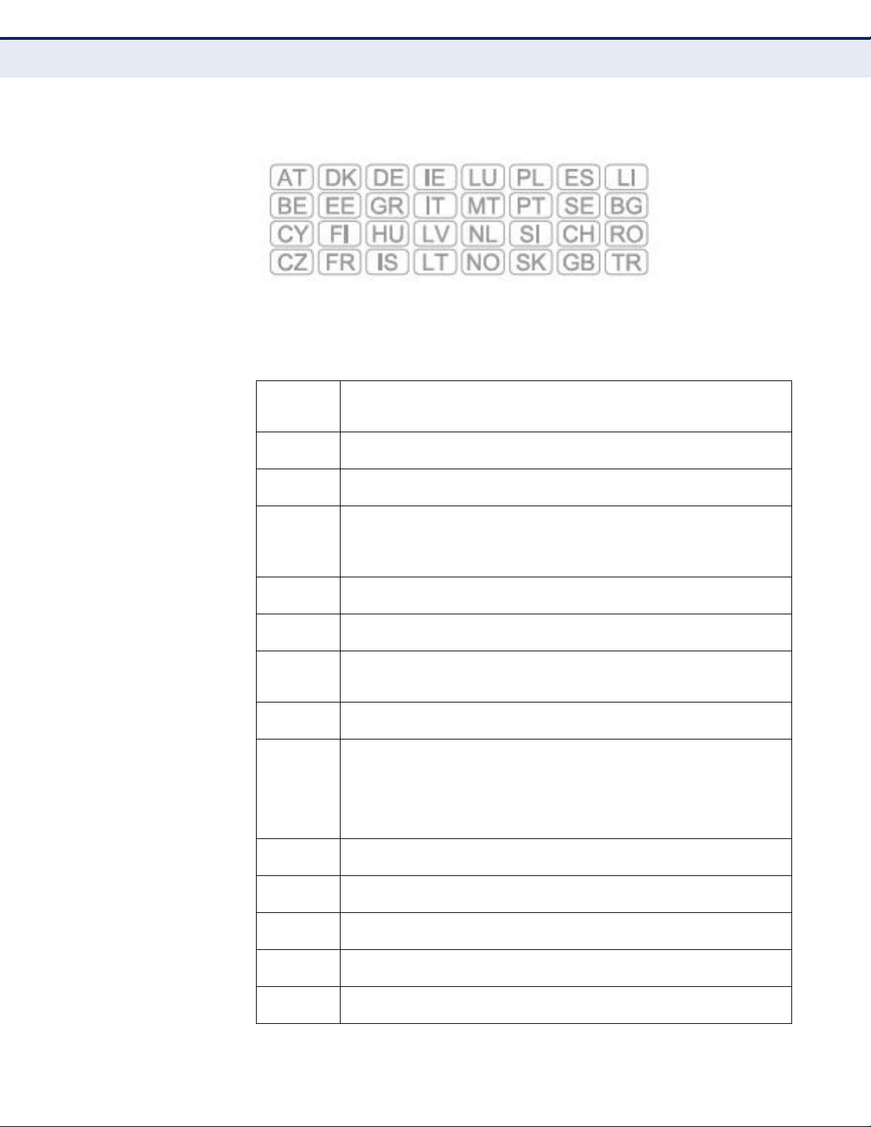
This equipment may be operated in:
The official CE certificate of conformity can be downloaded by selecting the
relevant model/ part number from www.smc.com -> support -> download.
Bulgarian
Български
Czech
Česky
Danish
Dansk
Dutch
Nederlands
English Hereby, Manufacturer, declares that this Radio LAN device is in compliance with the
Estonian
Eesti
Finnish
Suomi
French
Français
German
Deutsch
Greek
Ελληνική
Hungarian
Magyar
Italian
Italiano
Latvian
Latviski
Lithuanian
Lietuvių
С настоящето, SMC Networks декларира, че това безжично устройство е в
съответствие със съществените изисквания и другите приложими разпоредби на
Директива 1999/5/EC.
Manufacturer tímto prohlašuje, že tento Radio LAN device je ve shodě se základními
požadavky a dalšími příslušnými ustanoveními směrnice 1999/5/ES.
Undertegnede Manufacturer erklærer herved, at følgende udstyr Radio LAN device
overholder de væsentlige krav og øvrige relevante krav i direktiv 1999/5/EF
Hierbij verklaart Manufacturer dat het toestel Radio LAN device in overeenstemming is
met de essentiële eisen en de andere relevante bepalingen van richtlijn 1999/5/EG
Bij deze Manufacturer dat deze Radio LAN device voldoet aan de essentiële eisen en aan
de overige relevante bepalingen van Richtlijn 1999/5/EC.
essential requirements and other relevant provisions of Directive 1999/5/EC.
Käesolevaga kinnitab Manufacturer seadme Radio LAN device vastavust direktiivi 1999/
5/EÜ põhinõuetele ja nimetatud direktiivist tulenevatele teistele asjakohastele sätetele.
Valmistaja Manufacturer vakuuttaa täten että Radio LAN device tyyppinen laite on
direktiivin 1999/5/EY oleellisten vaatimusten ja sitä koskevien direktiivin muiden ehtojen
mukainen.
Par la présente Manufacturer déclare que l'appareil Radio LAN device est conforme aux
exigences essentielles et aux autres dispositions pertinentes de la directive 1999/5/CE
Hiermit erklärt Manufacturer, dass sich dieser/diese/dieses Radio LAN device in
Übereinstimmung mit den grundlegenden Anforderungen und den anderen relevanten
Vorschriften der Richtlinie 1999/5/EG befindet". (BMWi)
Hiermit erklärt Manufacturer die Übereinstimmung des Gerätes Radio LAN device mit den
grundlegenden Anforderungen und den anderen relevanten Festlegungen der Richtlinie
1999/5/EG. (Wien)
με την παρουσα Manufacturer δηλωνει οτι radio LAN device συμμορφωνεται προσ τισ
ουσιωδεισ απαιτησεισ και τισ λοιπεσ σχετικεσ διαταξεισ τησ οδηγιασ 1999/5/εκ.
Alulírott, Manufacturer nyilatkozom, hogy a Radio LAN device megfelel a vonatkozó
alapvetõ követelményeknek és az 1999/5/EC irányelv egyéb elõírásainak.
Con la presente Manufacturer dichiara che questo Radio LAN device è conforme ai
requisiti essenziali ed alle altre disposizioni pertinenti stabilite dalla direttiva 1999/5/CE.
Ar šo Manufacturer deklarē, ka Radio LAN device atbilst Direktīvas 1999/5/EK būtiskajām
prasībām un citiem ar to saistītajiem noteikumiem.
Šiuo Manufacturer deklaruoja, kad šis Radio LAN device atitinka esminius reikalavimus ir
kitas 1999/5/EB Direktyvos nuostatas.
– 9 –
Page 10

C
OMPLIANCES
Maltese
Malti
Polish
Polski
Portuguese
Português
Romanian
Romană
Slovak
Slovensky
Slovenian
Slovensko
Spanish
Español
Swedish
Svenska
Turkish
Turk
Hawnhekk, Manufacturer, jiddikjara li dan Radio LAN device jikkonforma mal-ħtiġijiet
essenzjali u ma provvedimenti oħrajn relevanti li hemm fid-Dirrettiva 1999/5/EC.
Niniejszym Manufacturer oświadcza, że Radio LAN device jest zgodny z zasadniczymi
wymogami oraz pozostałymi stosownymi postanowieniami Dyrektywy 1999/5/EC.
Manufacturer declara que este Radio LAN device está conforme com os requisitos
essenciais e outras disposições da Directiva 1999/5/CE.
SMC Networks declară că acest dispozitiv fără fir respectă cerinţele esenţiale precum şi
alte dispoziţii relevante ale Directivei 1999/5/EC.
Manufacturer týmto vyhlasuje, že Radio LAN device spĺňa základné požiadavky a všetky
príslušné ustanovenia Smernice 1999/5/ES.
Manufacturer izjavlja, da je ta radio LAN device v skladu z bistvenimi zahtevami in ostalimi
relevantnimi določili direktive 1999/5/ES.
Por medio de la presente Manufacturer declara que el Radio LAN device cumple con los
requisitos esenciales y cualesquiera otras disposiciones aplicables o exigibles de la
Directiva 1999/5/CE
Härmed intygar Manufacturer att denna Radio LAN device står I överensstämmelse med
de väsentliga egenskapskrav och övriga relevanta bestämmelser som framgår av direktiv
1999/5/EG.
SMC Networks bu kablosuz cihazın temel gereksinimleri ve 1999/5/EC yonergesindeki
ilgili koşulları karşıladığını beyan eder.
SAFETY PRECAUTIONS
Read the following information carefully before operating the device. Please
follow the following precaution items to protect the device from risks and
damage caused by fire and electric power:
◆ Use the power adapter that is included with the device package.
◆ Pay attention to the power load of the outlet or prolonged lines. An
overburdened power outlet or damaged cords and plugs may cause
electric shock or fire. Check the power cords regularly, if you find any
damage, replace it at once.
◆ Proper space for heat dissipation is necessary to avoid any damage
caused by device overheating. The ventilation holes on the device are
designed for heat dissipation to ensure that the device works normally.
Do not cover these ventilation holes.
◆ Do not put this device close to a place where a heat source exits or high
temperature occurs. Avoid placing the device in direct sunshine.
◆ Do not put this device close to a place which is damp or wet. Do not
spill any fluid on this device.
◆ Please follow the instructions in the user manual/quick install guide
carefully to connect the device to your PC or other electronic product.
Any invalid connection may cause a power or fire risk.
◆ Do not place this device on an unstable surface or support.
– 10 –
Page 11

C
OMPLIANCES
PRÉCAUTIONS DE SÉCURITÉ
Lisez attentivement les informations suivantes avant d’utiliser votre
appareil. Respectez toutes les précautions afin de protéger l’appareil des
risques et dégâts provoqués par un incendie et l’alimentation électrique :
◆ Utilisez exclusivement l’adaptateur d’alimentation fourni avec cet
appareil.
◆ Faites attention à la puissance de charge de la prise de courant ou des
rallonges électriques. Une prise surchargée ou des cordons et des
fiches endommagés peuvent provoquer une électrocution ou un
incendie. Vérifiez régulièrement votre câble électrique. Si vous
constatiez le moindre défaut, remplacez-le immédiatement.
◆ Il est primordial de laisser suffisamment d’espace autour de l’appareil
pour permettre la dissipation de la chaleur et éviter les dégâts
provoqués par une surchauffe de l’appareil. Les orifices de ventilation
de l’appareil sont conçus pour permettre la dissipation thermique et
garantir le bon fonctionnement de l’appareil. Ne couvrez jamais ces
orifices.
◆ Ne placez pas cet appareil à proximité d’une source de chaleur ou dans
un endroit exposé à des températures élevées. Evitez également de
l’exposer à la lumière directe du soleil.
◆ Ne placez pas cet appareil à proximité d’un lieu humide ou mouillé.
Prenez garde à ne renverser aucun liquide sur cet appareil.
◆ Merci de suivre les instructions du manuel d'utilisateur / guide
d’installation rapide attentivement pour connecter l'appareil à votre PC
ou à tout autre produit électronique. Toute connexion non valide peut
provoquer un problème électrique ou un risque d'incendie.
◆ Ne placez pas cet appareil sur une surface ou un support instable.
SICHERHEITSMAßNAHMEN
Lesen Sie vor der Inbetriebnahme des Gerätes aufmerksam die
nachstehenden Informationen. Bitte befolgen Sie die nachstehenden
Sicherheitsmaßnahmen, damit das Gerät nicht beschädigt wird oder
Gefahren durch Brand oder elektrische Energie entstehen:
◆ Verwenden Sie nur das beim Gerät mitgelieferte Netzteil.
◆ Achten Sie auf die Last der Steckdose oder des Verlängerungskabels.
Eine überlastete Steckdose oder beschädigte Kabel und Stecker können
Stromschläge und Brand verursachen. Prüfen Sie die Netzkabel
regelmäßig. Ersetzen Sie sie umgehend, falls sie beschädigt sind.
◆ Achten Sie zur Vermeidung von Geräteschäden aufgrund von
Überhitzung darauf, dass genügend Freiraum zur Wärmeabfuhr
vorhanden ist. Die Belüftungsöffnungen am Gerät dienen der
Wärmeabfuhr und damit der Gewährleistung eines normalen
Gerätebetriebs. Decken Sie diese Belüftungsöffnungen nicht ab.
– 11 –
Page 12

C
OMPLIANCES
◆ Stellen Sie dieses Gerät nicht in der Nähe von Wärmequellen oder an
Orten mit hohen Temperaturen auf. Platzieren Sie das Gerät nicht im
direkten Sonnenlicht.
◆ Stellen Sie dieses Gerät nicht an feuchten oder nassen Orten auf.
Achten Sie darauf, keine Flüssigkeiten über dem Gerät zu verschütten.
◆ Befolgen Sie die Hinweise im Benutzerhandbuch (bzw. in der
Kurzanleitung) zum Anschluß des Gerätes an einen PC oder ein anderes
Elektrogerät. Jegliche unzulässige Verbindung birgt die Gefahr von
Stromschlägen und Brandgefahr.
◆ Platzieren Sie dieses Gerät nicht auf einer instabilen Oberfläche oder
Halterung.
PRECAUCIONES DE SEGURIDAD
Lea la siguiente información detenidamente antes de utilizar el dispositivo.
Siga las indicaciones de precaución que se mencionan a continuación para
proteger el dispositivo contra riesgos y daños causados por el fuego y la
energía eléctrica:
◆ Utilice el adaptador de alimentación incluido en el paquete del
dispositivo.
◆ Preste atención a la carga de potencia de la toma de corriente o de los
alargadores. Una toma de corriente sobrecargada o líneas y enchufes
dañados pueden provocar descargas eléctricas o un incendio.
Compruebe los cables de alimentación con cierta frecuencia. Si detecta
algún daño, reemplácelos inmediatamente.
◆ Deje un espacio adecuado para que se disipe el calor y evitar así
cualquier daño en el dispositivo causado por sobrecalentamiento. Los
orificios de ventilación del dispositivo están diseñados para disipar el
calor y garantizar que dicho dispositivo funciona con normalidad. No
tape estos orificios de ventilación.
◆ No coloque este dispositivo cerca de un lugar donde haya una fuente de
calor o temperaturas elevadas. Evite exponer el dispositivo a la luz
solar directa.
◆ No coloque este dispositivo junto a un lugar húmedo o mojado. No
derrame ningún fluido sobre el dispositivo.
◆ Por favor, siga cuidadosamente las instrucciones que figuran en el
manual/guía de instalación rápida para conectar el dispositivo a su PC o
a cualquier otro producto electrónico. Cualquier conexión no válida
podría causar riesgo de descarga o de incendio.
◆ No coloque este dispositivo en una superficie o soporte inestable.
– 12 –
Page 13

C
OMPLIANCES
PRECAUÇÕES DE SEGURANÇA
Leia atentamente as seguintes informações antes de utilizar o dispositivo.
Respeite as seguintes indicações de segurança para proteger o dispositivo
contra riscos e danos causados por fogo e energia eléctrica:
◆ Utilize o transformador incluído na embalagem do dispositivo.
◆ Respeite a potência da tomada eléctrica e das extensões. Uma tomada
eléctrica sobrecarregada ou cabos e fichas danificadas podem causar
choques eléctricos ou fogo. Verifique regularmente os cabos de
alimentação. Caso algum se encontre danificado, substitua-o
imediatamente.
◆ É necessário deixar algum espaço livre em volta do dispositivo para
dissipação de calor, de forma a evitar danos causados pelo
sobreaquecimento do dispositivo. Os orifícios de ventilação do
dispositivo foram concebidos para dissipar o calor e assegurar que o
mesmo funciona normalmente. Não bloqueie esses orifícios de
ventilação.
◆ Não coloque este dispositivo junto a fontes de calor ou em locais com
temperaturas elevadas. Evite colocar o dispositivo sob luz solar directa.
◆ Não coloque este dispositivo junto a locais molhados ou com humidade.
Não derrame líquidos sobre o dispositivo.
◆ Por favor siga atentamente as instruções do manual / guia de
instalação rápida para conectar o dispositivo ao seu PC ou a qualquer
outro dispositivo electrónico. Atenção que qualquer tipo de ligação
inválida pode originar risco de choque eléctrico ou de incêndio.
◆ Não coloque este dispositivo numa superfície ou suporte instáveis.
– 13 –
Page 14

C
OMPLIANCES
ENVIRONMENTAL STATEMENT
The manufacturer of this product endeavours to sustain an
environmentally-friendly policy throughout the entire production process.
This is achieved though the following means:
◆ Adherence to national legislation and regulations on environmental
production standards.
◆ Conservation of operational resources.
◆ Waste reduction and safe disposal of all harmful un-recyclable by-
products.
◆ Recycling of all reusable waste content.
◆ Design of products to maximize recyclables at the end of the product’s
life span.
◆ Continual monitoring of safety standards.
END OF PRODUCT LIFE SPAN
This product is manufactured in such a way as to allow for the recovery and
disposal of all included electrical components once the product has reached
the end of its life.
MANUFACTURING MATERIALS
There are no hazardous nor ozone-depleting materials in this product.
DOCUMENTATION
All printed documentation for this product uses biodegradable paper that
originates from sustained and managed forests. The inks used in the
printing process are non-toxic.
– 14 –
Page 15
ABOUT THIS GUIDE
PURPOSE This guide gives specific information on how to install the ADSL Gateway
Router and its physical and performance related characteristics. It also
gives information on how to operate and use the management functions of
the ADSL Gateway Router.
AUDIENCE This guide is for users with a basic working knowledge of computers. You
should be familiar with Windows operating system concepts.
CONVENTIONS The following conventions are used throughout this guide to show
information:
N
OTE
:
Emphasizes important information or calls your attention to related
features or instructions.
C
AUTION
damage the system or equipment.
W
ARNING
:
Alerts you to a potential hazard that could cause loss of data, or
:
Alerts you to a potential hazard that could cause personal injury.
REVISION HISTORY This section summarizes the changes in each revision of this guide.
MARCH 2012 REVISION
This is the first revision of this guide.
– 15 –
Page 16

CONTENTS
WARRANTY AND PRODUCT REGISTRATION 4
C
OMPLIANCES 5
BOUT THIS GUIDE 15
A
C
ONTENTS 16
F
IGURES 21
ABLES 24
T
SECTION I GETTING STARTED 25
1INTRODUCTION 26
Features and Benefits 26
Description of Hardware 27
Power Connector 29
Power Button 29
WLAN Button 29
WPS Button 29
Reset Button 29
2INSTALLING THE ROUTER 30
Package Contents 30
System Requirements 30
Cable Connections 31
Powering On 32
Configuring the TCP/IP Protocols 32
SECTION II WEB CONFIGURATION 35
3SYSTEM CONFIGURATION 36
Using the Web Interface 36
– 16 –
Page 17

C
ONTENTS
Home Page 37
Setup Wizard 40
Step 1 - Getting Started 40
Step 2 - Time Zone 40
Step 3 - ADSL Settings 41
Step 4 - Wireless Settings 43
Step 4 - Configuration Saving 44
4DEVICE INFORMATION 45
System Status 45
LAN Status 46
WLAN Status 47
WAN Status 48
Port Mapping 49
Traffic Statistics 50
DSL Statistics 51
ARP Table 52
5 WLAN CONFIGURATION 54
WLAN Basic Settings 55
Advanced Settings 57
Wireless Security Setup 59
Common Wireless Parameters 59
WEP Security 60
WPA Security 62
Access Control 63
Wi-Fi Protected Setup (WPS) 65
MBSSID 66
WDS 68
6 LAN SETTINGS 72
LAN Interface 73
IPv6 LAN Configuration 74
DHCP Settings 76
DHCP Disabled 76
DHCP Relay 77
DHCP Server 78
DHCP Static IP 80
– 17 –
Page 18

C
ONTENTS
7 WAN SETTINGS 81
Channel Configuration 82
ATM Settings 84
ADSL Settings 86
8SERVICES 88
DNS Settings 89
DNS Server 89
IPv6 DNS 89
DDNS 90
Access Control Lists 92
LAN ACLs 92
WAN ACLs 93
IP/Port Filtering 95
NAT/NAPT Settings 97
Virtual Servers 97
NAT Exclude IP 99
NAT Forwarding 99
NAT ALG and Pass-Through 100
NAT Port Trigger 101
FTP ALG Configuration 102
NAT IP Mapping 102
Quality of Service 103
MAC Filtering 105
DMZ 106
URL Blocking 107
Software Forbidden 108
DoS 109
IGMP Proxy Configuration 111
RIP Configuration 113
ARP Binding Configuration 114
9ADVANCED 115
Bridge Setting 116
Log Setting 117
Routing Configuration 118
UPnP 120
SNMP Protocol Configuration 121
– 18 –
Page 19

C
ONTENTS
System Time Configuration 122
Other Advanced Configuration 123
Port Mapping 124
10 DIAGNOSTICS 125
Diagnostic Test 126
Ping 127
Ping6 127
Traceroute 128
ADSL Tone Diagnostics 130
11 ADMINISTRATION SETTINGS 132
Commit/Reboot 133
Backup/Restore Settings 134
Password Setup 135
Upgrade Firmware 136
TR-069 Configuration 137
SECTION III APPENDICES 140
ATROUBLESHOOTING 141
Diagnosing Gateway Indicators 141
If You Cannot Connect to the Internet 142
Problems Accessing the Management Interface 142
BHARDWARE SPECIFICATIONS 143
Physical Characteristics 143
Wireless Characteristics 144
Software Features 144
Standards 146
Compliances 146
CCABLES AND PINOUTS 147
Twisted-Pair Cable Assignments 147
10/100BASE-TX Pin Assignments 148
Straight-Through Wiring 148
Crossover Wiring 149
RJ-11 Port 150
– 19 –
Page 20

C
ONTENTS
GLOSSARY 151
I
NDEX 154
– 20 –
Page 21

FIGURES
Figure 1: Top Panel 27
Figure 2: Rear Panel 28
Figure 3: Front Panel LEDs 28
Figure 4: Connecting the Router 31
Figure 5: Web Login 36
Figure 6: Home Page 37
Figure 7: Wizard Step 1 - Getting Started 40
Figure 8: Wizard Step 2 - Time Zone Configuration 40
Figure 9: Wizard Step 3 - ADSL Settings 41
Figure 10: Wizard Step 4 - Wireless Settings 43
Figure 11: Wizard Step 3 - Configuration Saving 44
Figure 12: System Status 45
Figure 13: Status - LAN 46
Figure 14: Status - WLAN 47
Figure 15: Status - WAN 48
Figure 16: Status - Port Mapping 49
Figure 17: Status - Traffic Statistics 50
Figure 18: Status - DSL Statistics 51
Figure 19: Status - ARP Table 52
Figure 20: WLAN Basic Settings 55
Figure 21: Wireless Security Setup - Advanced Settings 57
Figure 22: Wireless Security Setup - None 59
Figure 23: Wireless Security Setup - None 60
Figure 24: Wireless Security Setup - WEP 60
Figure 25: Wireless Security Setup - WEP Key Setup 61
Figure 26: Wireless Security Setup - WPA/WPA2 Setup 62
Figure 27: Wireless Security Setup - Wireless Access Control 64
Figure 28: WPS Configuration 65
Figure 29: Second BSSID 67
Figure 30: WDS Configuration 68
Figure 31: WDS Wireless Setup 69
– 21 –
Page 22

F
IGURES
Figure 32: LAN Basic Setup 69
Figure 33: Disabling DHCP 70
Figure 34: LAN Configuration 73
Figure 35: IPv6 LAN Configuration 74
Figure 36: DHCP Disabled 76
Figure 37: DHCP Relay 77
Figure 38: DHCP Server 78
Figure 39: Device IP Range Table 79
Figure 40: DHCP Static IP Assignment 80
Figure 41: WAN Configuration 82
Figure 42: ATM Settings 84
Figure 43: ATM Settings 86
Figure 44: DNS Server Configuration 89
Figure 45: IPv6 DNS Server Configuration 89
Figure 46: DDNS DynDns 90
Figure 47: LAN ACL Configuration 92
Figure 48: WAN ACL Configuration 93
Figure 49: IP/Port Filtering Settings 95
Figure 50: NAT — Virtual Servers 98
Figure 51: NAT — Exclude IP 99
Figure 52: NAT Forwarding Settings 99
Figure 53: NAT ALG and Pass-Through 100
Figure 54: NAT — Port Trigger 101
Figure 55: NAT — FTP ALG Configuration 102
Figure 56: NAT — IP Mapping 102
Figure 57: Quality of Service 103
Figure 58: MAC Filtering Settings 105
Figure 59: DMZ Settings 106
Figure 60: URL Blocking Settings 107
Figure 61: Software Forbidden Settings 108
Figure 62: DoS Settings 109
Figure 63: IGMP Proxy Configuration 112
Figure 64: RIP Configuration 113
Figure 65: ARP Binding Configuration 114
Figure 66: Bridge Setting 116
Figure 67: Log Setting 117
– 22 –
Page 23

F
IGURES
Figure 68: Routing Configuration 118
Figure 69: UPnP 120
Figure 70: SNMP Configuration 121
Figure 71: System Time Configuration 122
Figure 72: Other Advanced Configuration 123
Figure 73: Port Mapping Configuration 124
Figure 74: Diagnostic Test 126
Figure 75: Ping 127
Figure 76: Ping Result 127
Figure 77: Ping6 127
Figure 78: Traceroute 128
Figure 79: Traceroute Result 129
Figure 80: ADSL Tone Diagnostics 130
Figure 81: Commit/Reboot 133
Figure 82: Rebooting 133
Figure 83: Backup/Restore Settings 134
Figure 84: Password Setup 135
Figure 85: Upgrade Firmware 136
Figure 86: TR-069 Configuration 137
Figure 87: RJ-45 Connector 147
Figure 88: Straight-through Wiring 148
Figure 89: Crossover Wiring 149
Figure 90: RJ-11 Wiring 150
– 23 –
Page 24

TABLES
Table 1: LED Display Indicators 28
Table 2: Configuration Menu 37
Table 3: LED Troubleshooting Chart 141
Table 4: Web Access Troubleshooting Chart 142
Table 5: 10/100BASE-TX MDI and MDI-X Port Pinouts 148
Table 6: RJ-11 Port Pinouts 150
– 24 –
Page 25

S
ECTION
GETTING STARTED
This section provides an overview of the ADSL Gateway Router, and
describes how to install and mount the unit.
This section includes these chapters:
◆ “Introduction” on page 26
◆ “Installing the Router” on page 30
I
– 25 –
Page 26

1 INTRODUCTION
The Barricade ADSL Gateway Router (SMC7904WBRAS-N2 v2) is an
ADSL2/2+ modem contained in a compact unit. The router enables
multiple wired and wireless users to securely access the Internet through a
single-user account with the ADSL service provider. The router provides
four 10/100 Mbps Ethernet ports for connection to end users, an IEEE
802.11b/g/n wireless interface, and one ADSL line for connection to the
Internet service provider.
FEATURES AND BENEFITS
The features of the ADSL Gateway Router include:
◆ Full-rate ADSL router, support for Router and Bridge modes
◆ ITU G.992.3(ADSL2) and ITU G.992.5(ADSL2+)
◆ ITU G.992.1 (G.dmt) Annex A and ITU G.992.2 (G.lite)
◆ ANSI T1.413 Issue 2
◆ Provides 24 Mbps downstream and 1 Mbps upstream
◆ Maximum transmission range: 5.4 Kilometers
◆ Four Ethernet ports, 10/100 Mbps Auto-MDI/MDIX
◆ 802.11n 2.4 GHz radio supporting four SSID interfaces
◆ Friendly web-based user interface for configuration
◆ Configurable as a DHCP server on your network
◆ Compatible with all standard Internet applications
◆ Industry standard and interoperable DSL interface
◆ Simple web-based status page displays a snapshot of your
configuration, and links to the configuration pages.
◆ Downloadable flash software upgrades
◆ Support of up to 8 Permanent Virtual Circuits (PVC)
◆ Support of up to 8 PPPoE sessions
– 26 –
Page 27
DESCRIPTION OF HARDWARE
This ADSL Gateway Router is a high bit-rate Digital Subscriber Line (DSL)
modem that can connect to an ADSL Internet service provider.
This unit provides the following ports on the rear panel:
◆ One RJ-11 port for connection to your ADSL service provider’s incoming
line.
◆ Four RJ-45 ports for connection to PCs, or to a 10/100BASE-TX
Ethernet Local Area Network switch. The ports operate at 10/100 Mbps,
half/full duplex. It supports automatic MDI/MDI-X operation, so you can
use straight-through cables for all network connections. (See “10/
100BASE-TX Pin Assignments” on page 148.)
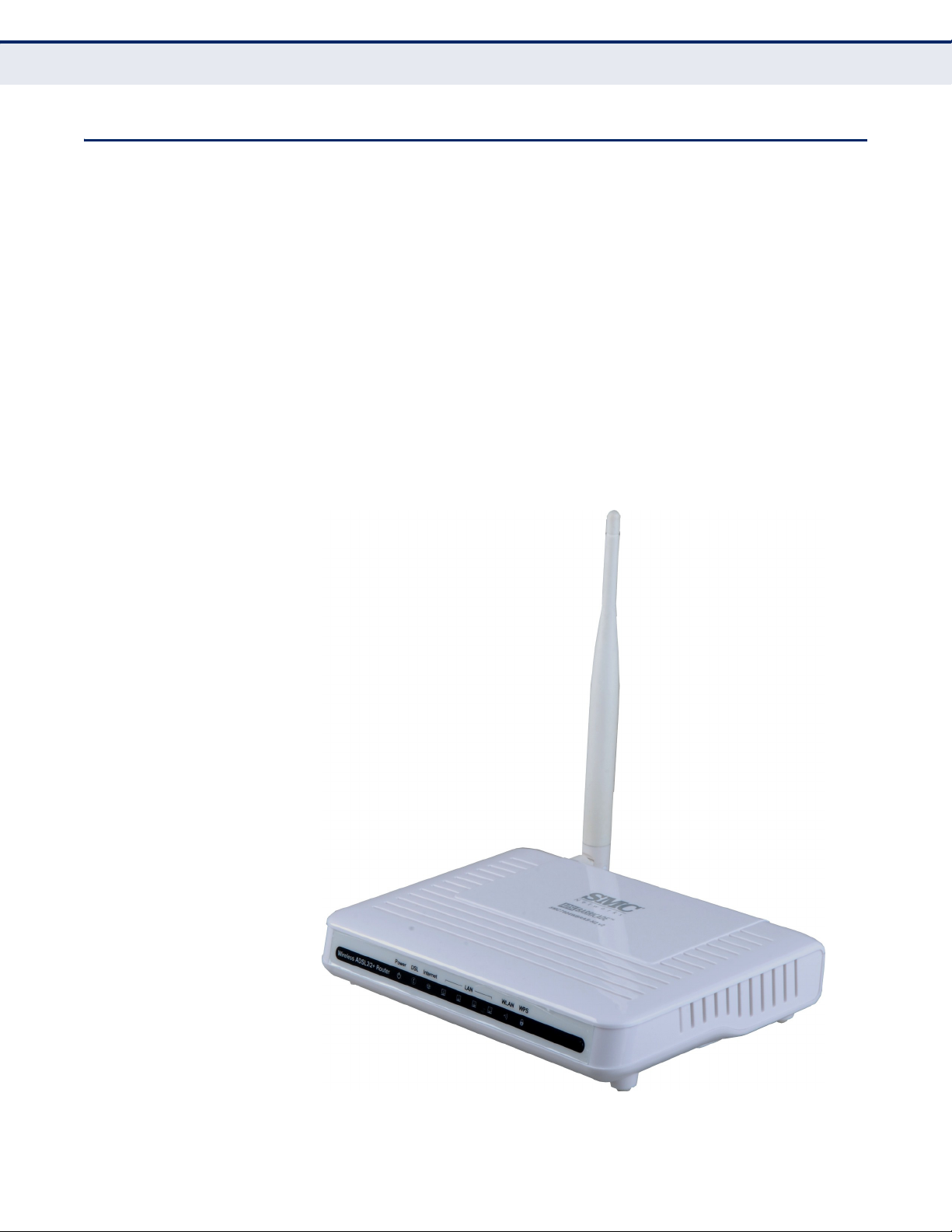
The following two figures show the components of the Gateway:
Figure 1: Top Panel
C
HAPTER
1
| Introduction
Description of Hardware
– 27 –
Page 28
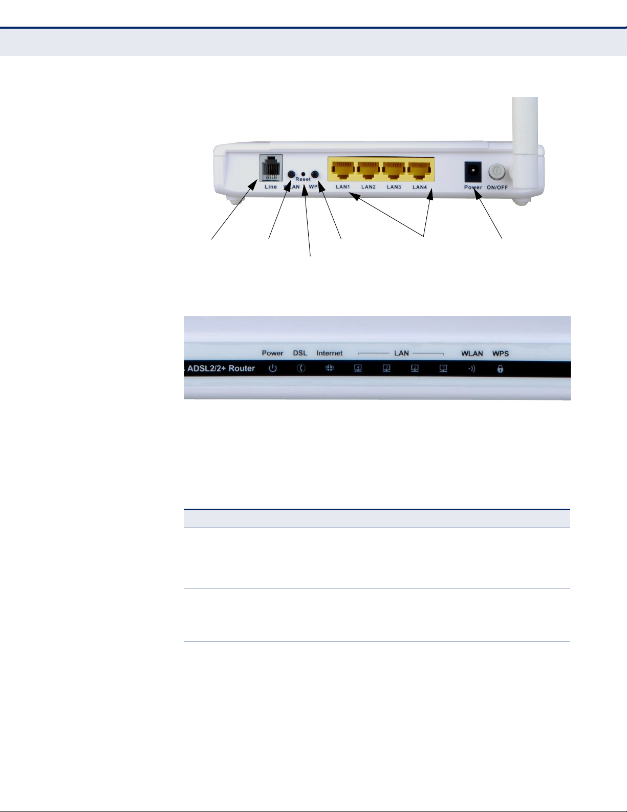
Figure 2: Rear Panel
WAN Port
Power Socket and
On/Off Switch
WLAN On/Off
Ethernet Ports
Reset Button
WPS Button
Figure 3: Front Panel LEDs
C
HAPTER
1
| Introduction
Description of Hardware
The ADSL Gateway Router includes key system and port indicators that
simplify installation and network troubleshooting. The LEDs, which are
located on the top of the unit for easy viewing, are described in the
following table.
Table 1: LED Display Indicators
LED Status Description
Power On Green The router is being supplied with power.
On Red The router is running its self-test or the self-test has
Off The router is not receiving power.
DSL On Green The DSL Line port has a link with the service provider.
Fast Blinking Green A DSL link is being established with the service provider.
Slow Blinking Green No DSL signal detected.
Internet On Green The Internet connection is in its normal routing mode
Blinking Green Internet data is being transmitted in routing mode.
On Red The Internet connection has failed after successful
Off The device is in bridge mode.
failed.
(for example, PPP dial-up is successful), but no data is
being transmitted.
synchronization in routing mode (for example, PPP dialup has failed).
– 28 –
Page 29

C
HAPTER
Table 1: LED Display Indicators (Continued)
LED Status Description
LAN
(1-4)
WLAN On Green The Wi-Fi radio is enabled.
WPS On Green WPS is activated and the router is waiting for negotiation
On Green Ethernet port has a valid link with attached device.
Blinking Green Data is being transmitted or received on the port.
Off Ethernet port has no link with an attached device.
Blinking Green Data is being transmitted through the WLAN interface.
Off The Wi-Fi radio is disabled.
with wireless clients.
Off WPS is not activated.
1
| Introduction
Description of Hardware
POWER CONNECTOR The ADSL Gateway Router must be powered with its supplied power
adapter. Failure to do so results in voiding of any warrantly supplied with
the product. The power adapter automatically adjusts to any voltage
between 100~240 volts at 50 or 60 Hz, and supplies 12 volts DC power to
the unit. No voltage range settings are required.
POWER BUTTON The ADSL Gateway Router has a power button. When the AC power
adapter is attached and connected to a power source, the power button
must be depressed to power on the unit.
WLAN BUTTON Turns the ADSL Gateway Router’s Wi-Fi radio on or off. The WLAN LED on
the front panel indicates when the Wi-Fi radio is enabled.
WPS BUTTON Push this button to start WPS authentication of a wireless device. After a
device is successfully added to the network by WPS, the WPS LED will
remain on for about 5 minutes and then turn off.
RESET BUTTON This button is used to restore the factory default configuration. If you press
and hold down the button for 8 seconds or more, any configuration
changes you may have made are removed, and the factory default
configuration is restored to the unit.
– 29 –
Page 30

2 INSTALLING THE ROUTER
Before installing the ADSL Gateway Router, verify that you have all the
items listed in “Package Contents.” If any items are missing or damaged,
contact your local distributor. Also, be sure you have all the necessary tools
and cabling before installing the router.
PACKAGE CONTENTS
After unpacking the ADSL Gateway Router, check the contents of the box to
be sure that you have received the following components:
◆ Barricade ADSL Gateway Router, SMC7904WBRAS-N2 v2
◆ RJ-45 Category 5 network cable
◆ RJ-11 telephone cable
◆ ADSL splitter
◆ AC power adapter
◆ Quick Installation Guide
◆ Documentation CD
◆ SMC warranty information card
Please inform your dealer if there are any incorrect, missing, or damaged
parts. If possible, retain the carton, including the original packing materials
in case there is a need to return the unit for repair.
SYSTEM REQUIREMENTS
Before you start installing the router, make sure you can provide the right
operating environment. See the following installation requirements:
◆ A PC or Macintosh with a 10/100 Mbps Ethernet adapter card installed.
Or, a Windows PC with an available USB port.
◆ For Internet access, the computer must be configured for TCP/IP.
– 30 –
Page 31

CABLE CONNECTIONS
Category 5
UTP Cable
Computer
AC Power
Adapter
AC Power Outlet
Telephone Wall Jack
Standard
Telephone
Cable
Splitter
Telephone
C
HAPTER
2
| Installing the Router
Cable Connections
◆ Power requirements: 12 VDC using the included AC power adapter.
Make sure that a properly grounded power outlet is within 1.8m (6 ft)
of the router.
◆ The router should be located in a cool dry place, with at least
5 cm (2 in.) of space on all sides for ventilation.
◆ Place the router out of direct sunlight, and away from heat sources or
areas with a high amount of electromagnetic interference. The
temperature and humidity should be within the ranges listed in the
specifications.
The ADSL Gateway Router needs to be connected to the DSL telephone line
from the service provider, and to a computer or LAN switch.
Figure 4: Connecting the Router
To install the router, follow these steps:
1. Using standard telephone cable, connect the Line port on the included
ADSL splitter to the RJ-11 telephone wall jack providing the ADSL
service.
2. Using standard telephone cable, connect the Modem port on the
included ADSL splitter to the RJ-11 Line port on the ADSL Gateway
Router.
– 31 –
Page 32

C
HAPTER
2
| Installing the Router
Powering On
3. The Phone port on the ADSL splitter can be connected to a standard
telephone set using telephone cable.
4. Connect one end of the included Ethernet cable to an Ethernet port on
the ADSL Gateway Router, and the other end to a PC’s RJ-45 network
port. Alternatively, you can connect an Ethernet port to a LAN switch.
C
AUTION
twisted-pair cables with RJ-45 connectors that conform to FCC standards.
N
OTE
switch), you can use either straight-through or crossover cabling. (Refer to
“Cables and Pinouts” on page 147 for a description of cable types.)
N
OTE
Ethernet port does not exceed 100 meters (328 feet).
:
Do not plug a phone jack connector into any RJ-45 port. Use only
:
When connecting to any network device (such as a PC, hub or
:
Make sure the twisted-pair Ethernet cable connected to the router’s
POWERING ON
Plug the power adapter cord into the DC 12V power socket on the router,
and then plug the power adapter directly into a power outlet. Check the
LED marked “Power” on the top of the unit to be sure it is on. If the Power
indicator does not light up, refer to “Troubleshooting” on page 141.
If the router is properly configured, it will take about 30 seconds to
establish a connection with the ADSL service provider after powering up.
During this time the Link indicator will blink during synchronization. After
the ADSL connection has been established, the Link indicator will stay on.
CONFIGURING THE TCP/IP PROTOCOLS
To connect the router to a computer through its Ethernet port, the
computer must have an Ethernet network adapter card installed, and be
configured for the TCP/IP protocol. Your service provider will configure
TCP/IP for client computers automatically using a networking technology
known as Dynamic Host Configuration Protocol (DHCP).
Carry out the following steps to check that the computer’s Ethernet port is
correctly configured for DHCP.
WINDOWS 95/98/NT
1. Click “Start/Settings/Control Panel.”
2. Click the “Network” icon.
3. For Windows NT, click the “Protocols” tab.
– 32 –
Page 33

C
HAPTER
2
| Installing the Router
Configuring the TCP/IP Protocols
4. Select “TCP/IP” from the list of network protocols; this may include
details of adapters installed in your computer.
5. Click “Properties.”
6. Check the option “Obtain an IP Address.”
WINDOWS 2000
1. Click “Start/Settings/Network/Dial-up Connections.”
2. Click “Local Area Connections.”
3. Select “TCP/IP” from the list of network protocols.
4. Click on “Properties.”
5. Select the option “Obtain an IP Address.”
WINDOWS XP
1. Click “Start/Control Panel/Network Connections.”
2. Right-click the “Local Area Connection” icon for the adapter you want to
configure.
3. Highlight “Internet Protocol (TCP/IP).”
4. Click on “Properties.”
5. Select the option “Obtain an IP address automatically” and “Obtain DNS
server address automatically.”
WINDOWS VISTA
1. Click Start/Control Panel.
2. Double-click “Network and Sharing Center.”
3. Click “View status.”
4. Click “Properties.” If the “User Account Control” window appears, click
“Continue.”
5. Highlight “Internet Protocol Version 6 (TCP/IPv6)” or “Internet Protocol
Version 4 (TCP/IPv4),” and click “Properties.”
6. Select the option “Obtain an IP address automatically” and “Obtain DNS
server address automatically.”
MAC OS
1. Pull down the Apple Menu. Click “Control Panels” and select “TCP/IP.”
2. In the TCP/IP dialog box, verify that “Ethernet” is selected in the
“Connect Via:” field.
– 33 –
Page 34

C
HAPTER
2
| Installing the Router
Configuring the TCP/IP Protocols
3. If “Using DHCP Server” is already selected in the “Configure” field, your
computer is already configured for DHCP. Otherwise, select “Using
DHCP Server” in the “Configure” field and close the window.
4. Another box will appear asking whether you want to save your TCP/IP
settings. Click “Save.”
5. Your service provider will now be able to automatically assign an IP
address to your computer.
– 34 –
Page 35

S
ECTION
WEB CONFIGURATION
This section describes the basic settings required to access the web
management interface and provides details on configuring the Gateway.
This section includes these chapters:
◆ “System Configuration” on page 36
◆ “Device Information” on page 45
◆ “WLAN Configuration” on page 54
◆ “LAN Settings” on page 72
II
◆ “WAN Settings” on page 81
◆ “Services” on page 88
◆ “Advanced” on page 115
◆ “Diagnostics” on page 125
◆ “Administration Settings” on page 132
– 35 –
Page 36

3 SYSTEM CONFIGURATION
USING THE WEB INTERFACE
The router provides a web-based management interface for configuring
device features and viewing statistics to monitor network activity. This
interface can be accessed by any computer on the network using a
standard web browser (such as Internet Explorer 5.0, Netscape 6.2, Mozilla
Firefox 2.0, or above).
To make an initial connection to the management interface, connect a PC
to one of the router’s LAN ports. Set your PC with a static address within
the same subnet as that used by the router (that is, 192.168.2.x with the
subnet mask 255.255.255.0).
To access the configuration menu, follow these steps:
1. Use your web browser to connect to the management interface using
the default IP address of 192.168.2.1.
Figure 5: Web Login
2. Log in to the router’s management interface using this account:
Login ID: admin
Password: smcadmin
– 36 –
Page 37

C
HAPTER
N
OTE
:
It is strongly recommended to change the default password the first
3
| System Configuration
Using the Web Interface
time you access the web interface. For information on changing the
password, see “Password Setup” on page 135.
HOME PAGE When your web browser connects with the router’s web agent, the home
page is displayed as shown below. Basic information can be viewed using
the Status menu. To carry out detailed configuration tasks, use the other
menu items.
Figure 6: Home Page
The main menu is displayed on the left side of the screen. Click on any of
these items to open the sub-menu list. The information in this chapter is
organized to reflect the structure of the web management screens for easy
reference. The configuration pages include the options listed in the table
below. For details on configuring each feature, refer to the corresponding
page number.
Table 2: Configuration Menu
Menu Description Page
Wizard Starts the setup wizard 40
Status
System Shows hardware/software version numbers, DSL
LAN Shows the LAN IP and DHCP server settings 46
WLAN Shows wireless interface settings 47
WAN Shows WAN interface functional status (including
Port Mapping Shows the port mapping settings 49
Statistics
connection status, and Internet connection settings
connection mode – single or multiple service, IGMP), and
connection status
45
48
– 37 –
Page 38

C
HAPTER
3
| System Configuration
Using the Web Interface
Table 2: Configuration Menu (Continued)
Menu Description Page
Statistics Shows the network traffic statistics 50
DSL Statistics Shows the ADSL line statistics 51
ARP Shows entries in the ARP table 52
Wireless
Basic Settings Configures basic wireless settings 55
Advanced Settings Configures advanced wireless settings 57
Security Configures wireless security settings 59
Access Control Configures wireless access control settings 64
WPS Configures WPS security 65
MBSSID Enables multiple SSID interfaces 66
WDS Configures Wireless Distribution System settings 68
LAN Interface
LAN Interface Configures the LAN management interface, including IP
IPv6 LAN Config Configures IPv6 LAN settings 74
DHCP Config
DHCP Mode Sets DHCP server and DHCP relay settings 76
Static IP Configures static DHCP assignments 80
WAN Interface
Channel Config Configures the DSL channel settings 82
ATM Settings Configures DSL ATM settings 84
ADSL Settings Configures ADSL settings 86
Services
DNS
DNS Server Configures DNS server settings 89
IPv6 DNS Configures IPv6 DNS server settings 89
Dynamic DNS Configures DDNS settings 90
Access Control List
ACL Config Configures ACLs for LAN or WAN interfaces 92
IP/Port Filtering Configures IP filtering settings 95
address, and IGMP snooping on LAN side
73
NAT/NAPT
Virtual Server Configures the virtual server forwarding table 97
NAT Exclude IP Configures excluded IPs on the WAN interface 99
NAT Forwarding Configures forwarding for access to local servers 99
NAT ALG and PassThrough
NAT Port Trigger Restricts Internet access for specific ports 101
Configures NAT passthrough for specific application
protocols
– 38 –
100
Page 39

C
HAPTER
3
| System Configuration
Using the Web Interface
Table 2: Configuration Menu (Continued)
Menu Description Page
FTP ALG
Configuration
NAT IP Mapping Configures IP address mapping for NAT 102
IP QoS Configures IP-based QoS settings 103
MAC Filtering Configures MAC address filtering 105
DMZ Configures DMZ settings 106
URL Block Sets URL key words to block 107
Software Forbidden Blocks Internet access for specific software 108
DoS Setting Configures denial-of-service settings 109
IGMP Proxy Configures IGMP Proxy settings for multicast traffic 111
RIP Configures Routing Information Protocol settings 113
ARP Binding Configures Address Resolution Protocol binding 114
Advance
Configures FTP server and client ports 102
Bridge Setting Configures aging time and Spanning Tree settings 116
Log Setting Configures system log settings 117
Routing Configures static routing 118
UPnP Enables UPnP for the WAN interface 120
SNMP Configures SNMP settings 121
System Time Configures NTP time server settings 122
Others Configures Half Bridge settings 123
Port Mapping Maps LAN ports to WAN interfaces 124
Diagnostic
Diag-Test Runs diagnostic tests for the ADSL link 126
Ping Sends Ping echo requests to other devices 127
Ping6 Sends IPv6 Ping echo requests to other devices 127
Tra c e r o u t e Checks routes to other devices 128
ADSL Runs ADSL diagnostic tone tests 130
Admin
Commit/Reboot Reboots the unit and/or restores factory defaults 133
Backup/Restore Backs up or restores configuration settings 134
Password Setup Changes the web access passwords 135
Upgrade Firmware Upgrades the unit’s software version 136
Configure TR-069 Configures parameters for establishing a connection
between the router and an auto-configuration server
137
– 39 –
Page 40

SETUP WIZARD
C
HAPTER
3
| System Configuration
Setup Wizard
The Wizard is designed to help you configure the basic settings required to
get the ADSL Gateway Router up and running. Click “Wizard” in the main
menu to get started.
STEP 1 - GETTING
After reading the wizard welcome message, click Next to continue.
STARTED
Figure 7: Wizard Step 1 - Getting Started
STEP 2 - TIME ZONE Configure a Network Time Protocol (NTP) server to poll for time updates.
To synchronize the router with an NTP server, specify the IP address of a
public time server, select your local time zone, and click Next.
Figure 8: Wizard Step 2 - Time Zone Configuration
The following items are displayed on this page:
◆ Status – Enables or disables time synchronization with external
servers.
– 40 –
Page 41

C
HAPTER
3
| System Configuration
Setup Wizard
◆ Server IP – Specifies the IP address of a public NTP time server on the
Internet.
◆ Interval – Specifies the time interval for polling the NTP server.
◆ Time Zone – A drop-down box provides access to predefined time
zones. Each choice indicates it’s offset from GMT and lists at least one
major city or commonly known zone name covered by the time zone.
STEP 3 - ADSL
SETTINGS
The third page of the wizard configures the ADSL country settings, Internet
service provider, protocol, connection type and username and password.
Figure 9: Wizard Step 3 - ADSL Settings
The following items are displayed on the first page of the Wizard:
◆ Country — Choose your country of operation from the drop down
menu. If your country is not listed, contact your service provider for
detailed settings.
◆ Internet Service Provider — The chosen country will determine the
list of available Internet Service Providers. Choose the service provider
with which you have a contract.
◆ Protocol — The protocol used will be specified by your service
provider. Choose from the following options:
■
PPPoE — Point-to-Point Protocol over Ethernet (PPPoE).
■
PPPoA — Point-to-Point Protocol over Asynchronous Transfer Mode
(PPPoA).
– 41 –
Page 42

C
HAPTER
3
| System Configuration
Setup Wizard
■
1483 MER : DHCP — 1483 MER is an RFC standard MAC
Encapsulated Routing protocol.
■
1483 MER : Static IP — 1483 MER is an RFC standard MAC
Encapsulated Routing protocol.
■
1483 Bridged — The Bridged RFC 1483 Encapsulated Traffic over
ATM feature allows you to send bridged RFC 1483 encapsulated
packets over ATM switched virtual circuits (SVCs).
■
1483 Routed — Allows you to send routed RFC 1483 encapsulated
packets over ATM switched virtual circuits (SVCs).
■
IPoA — Dynamic IP over ATM (IPoA).
◆ Connection Type — Your connection type will also be specified by your
service provider. Choose from the following options:
■
VC-Mux — Virtual circuit multiplexing (VC-Mux).
■
LLC — Logical Link Control (LLC).
◆ VPI — The ATM Virtual Path Identifier. (Range: 0-255)
◆ VCI — The ATM Virtual Channel Identifier. (Range: 32-65535)
◆ Username — Enter the username provided by your service provider.
◆ Password — Enter the password provided by your service provider.
◆ Confirm Password — Re-enter your password.
– 42 –
Page 43

C
HAPTER
3
| System Configuration
Setup Wizard
STEP 4 - WIRELESS
SETTINGS
The fourth page of the wizard configures wireless settings for the ADSL
router.
Figure 10: Wizard Step 4 - Wireless Settings
The following items are displayed on the first page of the Wizard:
◆ WLAN Interface — Enables/disables the wireless 802.11b/g/n
interface.
◆ Band — Selects the operating band and mode. The router supports the
2.4 GHz band and can operate in any combination of 802.11b, g, or n
modes.
◆ SSID — Specifies an SSID (service set identifier) which must be the
same as that on all wireless clients that wish to associate with the unit.
◆ Encryption — Specifies the security used to protect your wireless
network. (Default: None)
■
None: Allows any wireless client within range to associate with the
ADSL/Router.
■
WEP: Provides a basic level of security using static shared keys that
are distributed to all clients. Be sure to configure at least one static
key. Alte rnative ly, enab le 802. 1X authentication to dynamically
create and distribute keys from a RADIUS server.
■
WPA(TKIP/AES): Wi-Fi Protected Access (WPA) using either a
static pre-shared key, or 802.1X authentication through a RADIUS
server. The encryption used is either TKIP or AES.
– 43 –
Page 44

C
HAPTER
■
WPA2(TKIP/AES): WPA2 using either a static pre-shared key, or
3
| System Configuration
Setup Wizard
802.1X authentication through a RADIUS server. The encryption
used is either TKIP or AES.
■
WPA2 Mixed: WPA and WPA2 using either a static pre-shared key,
or 802.1X authentication through a RADIUS server. Either TKIP or
AES encryption is used depending on the client.
STEP 4 -
CONFIGURATION
SAVING
The final step in the setup wizard saves the configuration changes. Click
Finish to complete the wizard, then click Save.
Figure 11: Wizard Step 3 - Configuration Saving
– 44 –
Page 45

4 DEVICE INFORMATION
The Status pages display information on hardware/software versions, LAN
and WAN connection status, statistics, and the ARP table.
SYSTEM STATUS
The System Status page displays the hardware and software versions, and
the WAN connection status and speed.
Click Status, System.
Figure 12: System Status
The following items are displayed on this page:
SYSTEM:
◆ Alias Name – An alias for the ADSL Router, enabling the device to be
uniquely identified on the network.
◆ Uptime – The length of time in minutes that the unit has been powered
on.
◆ Software Version – The current version of firmware running on the
unit.
◆ DSP Version – The current hardware version of the digital signal
processor (DSP).
DSL:
◆ Operational Status – Displays the status of the DSL connection.
– 45 –
Page 46

LAN STATUS
C
HAPTER
4
| Device Information
LAN Status
◆ Upstream Speed – The current upload speed of the DSL connection.
◆ Downstream Speed – The current download speed of the DSL
connection.
The ADSL Router LAN window displays basic LAN port settings including
DHCP information.
Figure 13: Status - LAN
The following items are displayed on this page:
LAN STATUS
Displays the basic information of the LAN port.
◆ IP Address — Displays an IP address for local area connection to the
ADSL Router.
◆ Subnet Mask — Displays the local subnet mask.
◆ DHCP Server — Displays whether the DHCP server has been enabled
or not.
◆ MAC Address — Displays the physical layer address of the LAN port.
DHCP CLIENT TABLE
Displays information on the DHCP configuration and lease time.
◆ Name — Displays the name of the client device.
◆ IP Address — Displays the DHCP Client IP address.
◆ MAC Address — Displays the physical layer address of the DHCP
Client.
– 46 –
Page 47
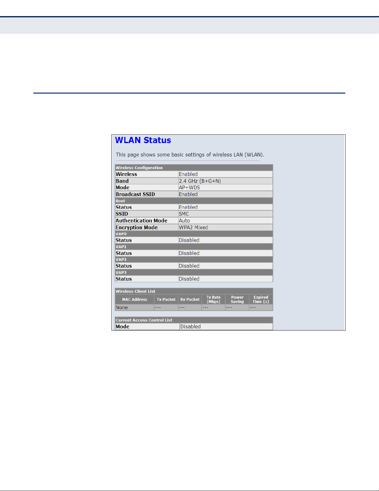
WLAN STATUS
C
HAPTER
4
| Device Information
WLAN Status
◆ Expiry(s) — Displays the duration of the lease time.
◆ Type — Indicates if the entry is dynamic or static.
The WLAN Status window displays basic wireless interface settings.
Figure 14: Status - WLAN
The following items are displayed on this page:
◆ Wireless Configuration — Indicates wireless interfaces that are
enabled. The router supports four multiple SSID interfaces: Root, and
VAP0-VAP3.
◆ Wireless Client List — Lists all wireless clients associated to the
router.
◆ Wireless Access Control List — Displays current wireless access
control list settings.
– 47 –
Page 48

WAN STATUS
C
HAPTER
4
| Device Information
WAN Status
The ADSL Router WAN window displays basic IPv4 and IPv6 WAN port
settings.
Figure 15: Status - WAN
The following items are displayed on this page:
◆ Interface — Displays the interface identifier.
◆ VPI/VCI — Displays the ATM channel identifiers.
◆ Encapsulation — Displays the encapsulation type chosen, either LLC
to VX-Mux.
◆ Default Route — Dipslays if a default route has been enabled.
◆ Protocol — Displays the protocol used for transmission of data packets
◆ IP Address — Displays the local IP address of the WAN port.
◆ Default Gateway — Displays the network route, or gateway used by
the unit when no other known route exists for a given IP packet's
destination address.
◆ Status — Specifies the status of the interface.
◆ DNS Servers — Specifies the IP addresses of DNS servers.
– 48 –
Page 49

PORT MAPPING
C
HAPTER
4
| Device Information
Port Mapping
The Port Mapping status shows the mapping of WAN and LAN interfaces to
specific groups.
Figure 16: Status - Port Mapping
The following items are displayed on this page:
◆ Status — Indicates if port mapping is enabled or disabled.
◆ Select — Indicates the group identification.
◆ Interfaces — Specifies the WAN and LAN interfaces in the group.
◆ Status — Indicates if the group mapping is enabled.
– 49 –
Page 50

TRAFFIC STATISTICS
C
HAPTER
4
| Device Information
Traffic Statistics
The ADSL Router Traffic Statistics - Interfaces window displays received
and transmitted packet statistics for all interfaces on the ADSL Router.
Figure 17: Status - Traffic Statistics
The following items are displayed on this page:
◆ Interface — Displays the interface on which traffic is being monitored.
◆ Rx Packet — Displays the total number of packets received by the
specified interface.
◆ Rx Error — Displays the total number of packet errors received by the
specified interface, if any.
◆ Rx Drop — Displays the total number of received packets dropped by
the specified interface.
◆ Tx Packet — Displays the total number of packets transmitted by the
specifed interface.
◆ Tx Error — Displays the total number of packet errors occured during
transmission by the specified interface.
◆ Tx Drop — Displays the total number of packets transmitted but
dropped by the specified interface.
◆ Refresh — Updates the statistical table for all interfaces.
– 50 –
Page 51

DSL STATISTICS
C
HAPTER
4
| Device Information
DSL Statistics
The ADSL Router DSL Statistics window displays received and transmitted
packet statistics for all interfaces on the ADSL Router.
Figure 18: Status - DSL Statistics
The following items are displayed on this page:
◆ ADSL Status — Displays the ADSL connection status (“activating”,
“up” or null).
◆ ADSL Mode — Displays the connection mode for the ADSL Router,
which is fixed at ADSL2+.
◆ Upstream — Displays the actual payload carried on the upstream
channels.
◆ Downstream — Displays the actual payload carried on the
downstream channels.
◆ Attentuation Downstream/Upstream (db) — Displays the amount
of attenuation in signal strength due to conductive losses in
transmission medium. Attenuation affects the propagation of waves
and signals in electrical circuits, expressed in decibels (dB).
– 51 –
Page 52

C
HAPTER
4
| Device Information
ARP Table
◆ SNR Margin Downstream/Upstream (db) — Displays the current
signal-to-noise margin expressed in decibels (dB). SNR is the ratio of
signal power to the noise power corrupting the signal.
◆ Vendor ID – The vendor name of the digital signal processor (DSP).
◆ DSP Version – The current hardware version of the digital signal
processor (DSP).
◆ CRC Errors — Displays the CRC (cyclic redunancy check) - a type of
function that takes as input a data stream of any length, and produces
as output a value of a certain space, commonly a 32-bit integer.
◆ Upstream/Downstream BER – The the rate at which bits in the data
stream that have been altered by noise.
◆ Up/Down Output Power — Displays the upstream/downstream
power level employed for ADSL port filtering.
◆ ES — Displays the total error seconds, the number of second intervals
during which there was one or more CRC anomalies, or one or more
Loss of Signal (LOS) or Loss of Framing (LOF) defects.
ARP TABLE
◆ SES — Displays the total severly errored seconds. The number of
second intervals containing 18 or more CRC-8 anomalies, one or more
Loss of Signal (LOS) defects, one or more Severely Errored Frame
(SEF) defects, or one or more Loss of Power (LPR) defects.
◆ UAS — Displays the total unavailable errored seconds, the number of
seconds during which the ADSL transceiver is powered up but not
available.
◆ ADSL Retrain — Retrains the DSL line.
The ARP page displays IP address to MAC address mapping entries
determined by the Address Resolution Protocol.
Figure 19: Status - ARP Table
– 52 –
Page 53

C
HAPTER
4
| Device Information
ARP Table
The following items are displayed on this page:
◆ IP Address — IP address of a local entry in the cache.
◆ MAC Address — MAC address mapped to the corresponding IP
address.
◆ Refresh — Sends a request to update the current parameters.
– 53 –
Page 54

5 WLAN CONFIGURATION
This chapter describes wireless configuration on the ADSL Router. The unit
contains an onboard IEEE 802.11b/g/n access point (AP), which provides
wireless data communications between the router and wireless devices.
WLAN Configuration contains the following sections:
◆ “WLAN Basic Settings” on page 55
◆ “Advanced Settings” on page 57
◆ “Wireless Security Setup” on page 59
◆ “Access Control” on page 64
◆ “Wi-Fi Protected Setup (WPS)” on page 65
◆ “MBSSID” on page 66
◆ “WDS” on page 68
– 54 –
Page 55

C
HAPTER
WLAN Basic Settings
5
| WLAN Configuration
WLAN BASIC SETTINGS
The unit’s access point can function in one of three modes, mixed
802.11b/g, 802.11b only, or 802.11g only. Also note that 802.11g is
backward compatible with 802.11b at slower data rates.
Note that the unit supports two virtual access point (VAP) interfaces.
Figure 20: WLAN Basic Settings
The following items are displayed on this page:
◆ Disable Wireless LAN Interface — Disables the Wireless LAN
interface. (Default: Enabled)
◆ Band — Defines the radio mode. (Default: 2.4Ghz (B+G))
◆ Mode — The unit can function as an access point alone, allowing
connection to wireless clients, or both access point and WDS (wireless
distribution system), allowing WDS transparent bridging between APs.
(Default: AP+WDS)
◆ SSID — The service set identifyer for the access point.
(Default: SMC)
◆ Channel Width — The router provides a channel bandwidth of 40 MHz
by default giving an 802.11g connection speed of 108 Mbps
(sometimes referred to as Turbo Mode) and a 802.11n connection
speed of up to 150 Mbps. Setting the HT Channel Bandwidth to 20 MHz
slows connection speed for 802.11g and 802.11n to 54 Mbps and 74
– 55 –
Page 56

C
HAPTER
5
| WLAN Configuration
WLAN Basic Settings
Mbps respectively and ensures backward compliance for slower
802.11b devices. (Default: 40MHz)
◆ Control Sideband — Specifies if the extension channel should be in
the Upper or Lower sideband. When a 40MHz channel bandwidth has
been set, the extension channel option will be enabled in the upper or
lower sideband. The extension channel allows you to get extra
bandwidth.
◆ Channel Number — The radio channel that the ADSL Router uses to
communicate with wireless clients. When multiple access points are
deployed in the same area, set the channel on neighboring access
points at least five channels apart to avoid interference with each other.
For example, you can deploy up to three access points in the same area
using channels 1, 6, 11. Note that wireless clients automatically set the
channel to the same as that used by the ADSL Router to which it is
linked. (Default: Auto; Range: 1~11)
◆ Radio Power (percent) — Adjusts the power of the radio signals
transmitted from the access point. The higher the transmission power,
the farther the transmission range. Power selection is not just a trade
off between coverage area and maximum supported clients. You also
have to ensure that high-power signals do not interfere with the
operation of other radio devices in the service area. (Default: 100%;
Range: 100%, 80%, 50%, 25%, 10%)
◆ Associated Clients — Opens a window that displays information on
current connected wireless clients.
– 56 –
Page 57

C
HAPTER
Advanced Settings
5
| WLAN Configuration
ADVANCED SETTINGS
The advanced radio configuration settings are described in the page that
follows.
Figure 21: Wireless Security Setup - Advanced Settings
The following items are displayed on this page:
◆ Authentication Type — Sets the basic authentication method.
◆ Fragment Threshold — Configures the minimum packet size that can
be fragmented when passing through the wireless interface.
Fragmentation of the PDUs (Package Data Unit) can increase the
reliability of transmissions because it increases the probability of a
successful transmission due to smaller frame size. If there is significant
interference present, or collisions due to high network utilization, try
setting the fragment size to send smaller fragments. This will speed up
the retransmission of smaller frames. However, it is more efficient to
set the fragment size larger if very little or no interference is present
because it requires overhead to send multiple frames. (Range: 2562346 bytes; Default: 2346 bytes)
◆ RTS Threshold — Sets the packet size threshold at which a Request to
Send (RTS) signal must be sent to a receiving station prior to the
sending station starting communications. The wireless interface sends
RTS frames to a receiving station to negotiate the sending of a data
frame. After receiving an RTS frame, the station sends a CTS (clear to
send) frame to notify the sending station that it can start sending data.
◆ Beacon Interval — The rate at which beacon signals are transmitted
from the wireless interface. The beacon signals allow wireless clients to
– 57 –
Page 58

C
HAPTER
5
| WLAN Configuration
Advanced Settings
maintain contact with the ADSL Router. They may also carry powermanagement information. (Range: 20-1000 TUs; Default: 100 TUs)
◆ DTIM Interval — The rate at which stations in sleep mode must wake
up to receive broadcast/multicast transmissions.
Known also as the Delivery Traffic Indication Map (DTIM) interval, it
indicates how often the MAC layer forwards broadcast/multicast traffic,
which is necessary to wake up stations that are using Power Save
mode. The default value of one beacon indicates that the access point
will save all broadcast/multicast frames for the Basic Service Set (BSS)
and forward them after every beacon. Using smaller DTIM intervals
delivers broadcast/multicast frames in a more timely manner, causing
stations in Power Save mode to wake up more often and drain power
faster. Using higher DTIM values reduces the power used by stations in
Power Save mode, but delays the transmission of broadcast/multicast
frames. (Range: 1-255 beacons; Default: 1 beacon)
◆ Data Rate — The maximum data rate at which the wireless interface
transmits multicast and broadcast packets. (Options: Auto, 1, 2, 5.5,
11, 6, 9, 18, 24, 36, 48, 54 Mbps; Default: Auto)
◆ Preamble Type — Sets the length of the signal preamble that is used
at the start of a data transmission. (Default: Long)
■
Long Preamble: Sets the preamble to long (192 microseconds).
Using a long preamble ensures the wireless interface can support all
802.11b and 802.11g clients.
■
Short Preamble: Sets the preamble according to the capability of
clients that are currently asscociated. Uses a short preamble (96
microseconds) if all associated clients can support it, otherwise a
long preamble is used. The wireless interface can increase data
throughput when using a short preamble, but will only use a short
preamble if it determines that all associated clients support it.
◆ Broadcast SSID — Enables/disables the wireless interface to
broadcast an SSID (service set identifier) to uniquely identify it on the
network.
◆ Aggregation — This option enables Mac Service Data Unit (MSDU)
aggregation. (Default: Enabled)
◆ Short GI — The guard interval between symbols helps receivers
overcome the effects of multipath delays. You can enable a short
interval to increase throughput. (Default: Enabled)
– 58 –
Page 59

C
HAPTER
Wireless Security Setup
5
| WLAN Configuration
WIRELESS SECURITY SETUP
Describes the wireless security settings for each VAP, including association
mode, encryption, and authentication.
Figure 22: Wireless Security Setup - None
COMMON WIRELESS
PARAMETERS
The following items are displayed all pages of the Wireless Security Setup:
◆ SSID TYPE — Selects the VAP to apply security settings to.
(Options: Root, VAP0-VAP3)
◆ Encryption — Selects the encryption type to deploy on the specified
VAP. The options are:
■
None: No security.
■
WEP: WEP is used as the multicast encryption cipher. You should
select WEP only when both WPA and WEP clients are supported.
■
WPA(TKIP/AES): WPA employs a combination of several
technologies to provide an enhanced security solution for 802.11
wireless networks. TKIP or AES is used as the multicast encryption
cipher.
■
WPA2(TKIP/AES): WPA2 – WPA was introduced as an interim
solution for the vulnerability of WEP pending the ratification of the
IEEE 802.11i wireless security standard. In effect, the WPA security
features are a subset of the 802.11i standard. WPA2 includes the
now ratified 802.11i standard, but also offers backward
compatibility with WPA. Therefore, WPA2 includes the same 802.1X
– 59 –
Page 60

C
HAPTER
5
| WLAN Configuration
Wireless Security Setup
and PSK modes of operation. TKIP or AES is used as the multicast
encryption cipher.
■
WPA2(Mixed): Clients using WPA or WPA2 are accepted for
authentication. TKIP or AES is used as the multicast encryption
cipher.
The following figures illustrate the various options available with each
security setting:
Figure 23: Wireless Security Setup - None
WEP SECURITY The following page describes the WEP security setup on the ADSL Router.
Figure 24: Wireless Security Setup - WEP
– 60 –
Page 61

C
HAPTER
Wireless Security Setup
5
| WLAN Configuration
The following items are displayed on this page:
◆ Set WEP Key — Configures the WEP key setup. This is displayed in the
screen below.
◆ Use 802.1x Authentication — Enables/disables 802.1x
authentication. When enabled the above screen displays.
◆ WEP 64bits/128bits — Selects between 64 bit and 128 bit keys.
RADIUS SERVER
◆ Port — Specifies the port number used to communicate with the
RADIUS server.
◆ IP Address — Specifies the IP address used to communicate with the
RADIUS server.
◆ Password — Specifies the key necessary for RADIUS server
authentication.
WEP KEY SETUP
The following page describes the WEP key setup.
Figure 25: Wireless Security Setup - WEP Key Setup
The following items are displayed on this page:
◆ SSID Type — Selects the VAP to configure the WEP security settings
to.
– 61 –
Page 62

C
HAPTER
5
| WLAN Configuration
Wireless Security Setup
◆ Authentication Type — Selects the authentication type to use.
Options are:
■
Open System: If you don’t set up any other security mechanism
on the access point, the network has no protection and is open to all
users. This is the default setting.
■
Shared Key: Sets the access point to use WEP shared keys. If this
option is selected, you must configure at least one key on the
access point and all clients.
■
Auto: Automatically selects the best authentication type to use.
◆ Key Length — Selects between 64 bit and 128 bit keys.
◆ Key Format — Selects the preferred method of entering WEP
encryption keys on the unit:
■
Alphanumeric: Enter keys as 5 alphanumeric characters for 64 bit
keys, 13 alphanumeric characters for 128 bit keys. This is the
default setting.
■
Hexadecimal: Enter keys as 10 hexadecimal digits (0-9 and A-F) for
64 bit keys, or 26 hexadecimal digits for 128 bit keys.
◆ Default Tx Key — Selects the default key used for transmission.
◆ Encryption Key 1~4 — Specifies the user defined WEP keys.
WPA SECURITY The following section describes WPA, WPA2 and WPA2-mixed settings.
Figure 26: Wireless Security Setup - WPA/WPA2 Setup
The following items are displayed on this page:
– 62 –
Page 63

C
HAPTER
Wireless Security Setup
5
| WLAN Configuration
◆ WPA Authentication Mode — Selects between modes of WPA
authentication. Options are:
■
Enterprise: Uses a RADIUS server for authentication. This applies
to enterprise deployment.
■
Personal: Uses a pre-shared key for authentication.
ENTERPRISE (RADIUS)
◆ Port — Specifies the port number used to communicate with the
RADIUS server.
◆ IP Address — Specifies the IP address used to communicate with the
RADIUS server.
◆ Password — Specifies the password necessary for access to RADIUS
server authentication.
PERSONAL (PRE-SHARED KEY)
◆ Pre-Shared Key Format — Selects the format of the pre-shared key
from the following options:
■
Passphrase: Enter a key as an easy-to-remember form of letters
and numbers. The string must be from 8 to 63 characters, which
can include spaces.
■
Hexadecimal: Enter a key as a string of 64 hexadecimal numbers.
◆ Pre-Shared Key — Enter the pre-shared key noting the type chosen.
– 63 –
Page 64

ACCESS CONTROL
C
HAPTER
5
| WLAN Configuration
Access Control
Access control configures ACLs (access control lists) which allow or deny
wireless traffic based on the sender’s MAC address.
Figure 27: Wireless Security Setup - Wireless Access Control
The following items are displayed on this page:
◆ Wireless Access Control Mode — Enables/disables ACLs on the ADSL
Router. Options are:
■
Disable: Disables all ACLs.
■
Allow Listed: Configures an allowed list of MAC addresses. Those
MAC addresses not in the allowed list will not be allowed to connect
to the wireless interface.
■
Deny Listed: Configures a denied list of MAC addresses. The MAC
addresses specified will not be allowed to connect to the wireless
interface.
◆ MAC Address — The specified MAC address in the ACL Allowed or
Denied list.
◆ Select — Selects a MAC address from the list.
◆ Delete Selected — Deletes a selected MAC address.
◆ Delete All — Deletes all entries from the ACL table.
– 64 –
Page 65

C
HAPTER
Wi-Fi Protected Setup (WPS)
5
| WLAN Configuration
WI-FI PROTECTED SETUP (WPS)
Wi-Fi Protected Setup (WPS) is designed to ease installation and activation
of security features in wireless networks. WPS has two basic modes of
operation, Push-button Configuration (PBC) and Personal Identification
Number (PIN). The WPS PIN setup is optional to the PBC setup and
provides more security. The WPS button on the router can be pressed at
any time to allow a single device to easily join the network.
The WPS Settings page includes configuration options for setting WPS
device PIN codes and activating the virtual WPS button.
Figure 28: WPS Configuration
The following items are displayed on this page:
◆ Disable WPS — Disables WPS configuration. (Default: Disabled)
◆ WPS Status — Displays if there is currently any WPS traffic connecting
to the router.
◆ Self PIN Number — Displays the PIN Code for the router. The default
is exclusive for each unit.
◆ Regenerate PIN — Click the button to generate a new PIN number
that is used by the router.
◆ Push Button Configuration — The “Start PBC” button has the same
effect as pressing the physical WPS button that is located on the rear of
the router. After clicking on the button you have up to two minutes to
activate WPS on a device that needs to join the network.
◆ Apply Changes — Applies the current WPS settings.
– 65 –
Page 66

MBSSID
C
HAPTER
5
| WLAN Configuration
MBSSID
◆ Reset — Resets the WPS settings to factory default values.
◆ Client PIN Number — Enters a PIN number of a wireless client device
that needs to join the network. Click “Start PIN” to activate the WPS
process.
This page configures up to four VAPs (virtual access points) on the ADSL
Router. Each VAP functions as a separate access point, and can be
configured with its own Service Set Identification (SSID) and security
settings. However, most radio signal parameters apply to both VAP
interfaces.
The VAPs function similar to a VLAN, with each VAP mapped to its own
VLAN ID. Traffic to specific VAPs can be segregated based on user groups
or application traffic. Each VAP can have its own wireless clients, whereby
the clients associate with these VAPs the same as they would with a
physical access point.
– 66 –
Page 67

C
HAPTER
MBSSID
5
| WLAN Configuration
Figure 29: Second BSSID
The following items are displayed on this page:
◆ Enable (VAP0-VAP3) — Enables up to four VAP interfaces on the
router. (Default: Disabled)
◆ SSID — Configures the service set identifier of a VAP on the wireless
interface.
– 67 –
Page 68

WDS
C
HAPTER
5
| WLAN Configuration
WDS
◆ Broadcast SSID — Enables/disables the wireless interface to
broadcast an SSID (service set identifier) to uniquely identify it on the
network.
◆ Relay Blocking — Blocks traffic between SSID interfaces.
◆ Authentication Type — Sets the basic authentication method for the
VAP interface.
Each access point radio interface can be configured to operate as a bridge,
which allows it to forward traffic directly to other access point units. To set
up bridge links between access point units, you must configure the wireless
Distribution System (WDS) forwarding table by specifying the wireless MAC
address of all units to which you want to forward traffic. Up to six WDS
bridge links can be specified for each unit in the wireless bridge network.
Figure 30: WDS Configuration
To set up WDS all connected routers should be in the same subnet, with
DHCP disabled on all routers not connected to the WAN and the MAC
address of each router set first.
Follow the steps detailed below:
1. The wireless setup must be the same on all connected routers.
– 68 –
Page 69

C
HAPTER
WDS
5
| WLAN Configuration
Figure 31: WDS Wireless Setup
2. The MAC addresses on all connected routers must be set.
3. Change the LAN address on routers so as to avoid an IP conflict.
Figure 32: LAN Basic Setup
– 69 –
Page 70

4. DIsable the DHCP server.
Figure 33: Disabling DHCP
C
HAPTER
5
| WLAN Configuration
WDS
– 70 –
Page 71

C
HAPTER
WDS
5
| WLAN Configuration
– 71 –
Page 72

6 LAN SETTINGS
This chapter describes LAN configuration on the ADSL Router.
You can use the web browser interface to access IP addressing only if the
ADSL Router already has an IP address that is reachable through your
network.
◆ “LAN Interface” on page 73
◆ “IPv6 LAN Configuration” on page 74
◆ “DHCP Settings” on page 76
– 72 –
Page 73

LAN INTERFACE
C
HAPTER
6
| LAN Settings
LAN Interface
By default, the ADSL Router is configured with the IP address 192.168.2.1,
subnet mask 255.255.255.0 and a default gateway of 192.168.2.1.
Figure 34: LAN Configuration
The following items are displayed on this page:
◆ Interface Name — Displays the name assigned to the interface.
◆ IP Address — Specifies an IP address for management of the ADSL
Router. Valid IP addresses consist of four decimal numbers, 0 to 255,
separated by periods. (Default: 192.168.2.1.)
◆ Subnet Mask — Indicates the local subnet mask.
(Default: 255.255.255.0)
◆ Secondary IP Address — Specifies a secondary IP address for
management of the unit.
◆ IGMP Snooping — Enables Internet Group Management Protocol
(IGMP) multicast filtering.
– 73 –
Page 74

◆ LAN Port — Selects the LAN port.
◆ Link Speed/Duplex Mode — Selects the port speed and duplex
mode, or sets the port for auto-negotiation.
◆ MAC Address Control — Filters out traffic with source MAC addresses
not configured in the table. For devices that need Internet access
through the LAN port, enter the MAC address and click Add.
IPV6 LAN CONFIGURATION
This section describes how to configure an initial IPv6 interface for
management access over the network, or for creating an interface to
multiple subnets. This router supports both IPv4 and IPv6, and can be
managed through either of these address types.
IPv6 includes two distinct address types – link-local unicast and global
unicast. A link-local address makes the router accessible over IPv6 for all
devices attached to the same local subnet. However, to connect to a larger
network with multiple segments, the router must be configured with a
global unicast address.
C
HAPTER
6
| LAN Settings
IPv6 LAN Configuration
Figure 35: IPv6 LAN Configuration
– 74 –
Page 75

C
HAPTER
6
| LAN Settings
IPv6 LAN Configuration
The following items are displayed on this page:
RA SETTING
◆ Enable — Enables IPv6 router advertisements on the router.
◆ M Flag — Sets the router advertisement “Managed address
configuration" flag. When set, the router will use DHCPv6 to obtain
stateful addresses.
◆ O Flag — Sets the router advertisement “other stateful configuration”
flag. When set, the router will attempt to acquire other non-address
configuration information (such as a default gateway or DNS).
◆ Max Interval — The amount of time that a remote IPv6 node is
considered reachable.
◆ Min Interval — The interval between transmitting IPv6 neighbor
solicitation messages.
◆ Prefix Mode — Enables manual or automatic configuration of IPv6
addresses on the router.
■
Auto — Enables automatic configuration of IPv6 addresses on
interfaces and enables IPv6 functionality on the router. The network
portion of the address is based on prefixes received in IPv6 router
advertisement messages, and the host portion is automatically
generated using the modified EUI-64 form of the interface identifier
(that is, the router’s MAC address).
■
Manual — If auto-configuration is not selected, then an address
must be manually configured using the fields described below.
◆ Prefix Address — The IPv6 address prefix sent in router
advertisements.
◆ Prefix Length — The length of the IPv6 address prefix sent in router
advertisements. For IPv6 unicast addresses, this is set to 64.
◆ Preferred Time — The time over which the configured address is
preferred.
◆ Valid Time — The time over which the configured address is valid.
DHCPV6 SETTING
◆ DHCPv6 Mode — The DHCPv6 mode setting.
■
None — DHCPv6 is disabled.
■
Manual — If auto-configuration is not selected, then an IPv6
address pool must be manually configured.
■
Auto — Enables automatic assignment of IPv6 addresses on the
router. The network portion of the address is based on prefixes
received in IPv6 router advertisement messages, and the host
– 75 –
Page 76

DHCP SETTINGS
C
HAPTER
6
| LAN Settings
DHCP Settings
portion is automatically generated using the modified EUI-64 form
of the client identifier (that is, the client MAC address).
◆ IPv6 Address Pool — The address range available for DHCPv6
assignment.
◆ Prefix Length — The length of the IPv6 address prefix sent in DHCPv6
assignments. For IPv6 unicast addresses, this is set to 64.
◆ Preferred Time — The time over which assigned addresses are
preferred.
◆ Valid Time — The time over which the assigned addresses are valid.
◆ DNS Servers — Specifies up to three IPv6 Domain Name servers for
IPv6 addresses.
The ADSL Router includes a Dynamic Host Configuration Protocol (DHCP)
server that can assign temporary IP addresses to any attached host
requesting the service, as well as a DHCP relay serivce that will route the
DHCP service to other subnets than that of the unit.
DHCP DISABLED By selecting “None,” you can disable DHCP on the ADSL Router.
Figure 36: DHCP Disabled
The following items are displayed on this page:
◆ DHCP Mode — When set to “None,” disables DHCP on the unit.
– 76 –
Page 77

C
HAPTER
6
| LAN Settings
DHCP Settings
DHCP RELAY Dynamic Host Configuration Protocol (DHCP) can dynamically allocate an
IP address and other configuration information to network clients that
broadcast a request. To receive the broadcast request, the DHCP server
would normally have to be on the same subnet as the client. However,
when the access point’s DHCP relay agent is enabled, received client
requests can be forwarded directly by the access point to a known DHCP
server on another subnet. Responses from the DHCP server are returned to
the access point, which then broadcasts them back to clients.
Figure 37: DHCP Relay
The following items are displayed on this page:
◆ DHCP Mode — When set to “DHCP Relay,” enables routing of the DHCP
service to units on a different subnet.
◆ Relay Server — Enter the address of the DHCP server for routing to
other units.
– 77 –
Page 78

C
HAPTER
6
| LAN Settings
DHCP Settings
DHCP SERVER The unit can support up to 253 local clients. Addresses are assigned to
clients from a common address pool configured on the unit. Configure an
address pool by specifying start and end IP addresses. Be sure not to
include the unit's IP address in the address pool range.
Figure 38: DHCP Server
The following items are displayed on this page:
◆ LAN IP Address — Displays the LAN IP address for management of
the ADSL Router. (Default: 192.168.2.1.)
◆ Subnet Mask — Displays the local subnet mask.
(Default: 255.255.255.0)
◆ DHCP Mode — When set to “DHCP Server,” enables the ADSL Router to
act as a DHCP server.
◆ Interface — Selects either the RJ-45 LAN ports, or wireless interfaces.
◆ IP Pool Range — Configures the IP address pool for the DHCP server
and determines how many IP addresses can be assigned.
N
OTE
:
Do not enter the ADSL Router’s LAN IP address as part of the IP Pool
range.
◆ Show Client — Displays the current DHCP client table.
◆ Default Gateway — Specifies the gateway address through which
traffic is routed from. Usually the LAN IP address of the ADSL Router
– 78 –
Page 79

C
HAPTER
6
| LAN Settings
DHCP Settings
◆ MAX Lease Time — Select a time limit for the use of an IP address
from the IP pool. When the time limit expires, the client has to request
a new IP address. The lease time is expressed in seconds.
(Default: 86400 seconds; Range: 60~86400 seconds; -1 indicates an
infinite lease time)
◆ Domain Name — Specifies the unique name used to identify the ADSL
Router on the network.
◆ DNS Servers — Sets up to three domain name server IP addresses.
◆ Set VendorClass IP Range — Click on this option to assign IP
address ranges to specific device types.
■
Device Name — Describes the device type.
■
Start/End Address — Specifies the IP addresses from the DHCP IP
pool to assign to this device type.
■
Router Address — Specifies a default router IP address to use for
traffic from this device.
■
Option 60 — Specifies the DHCP Option 60 vendor class identifier
that indicates the device type.
Figure 39: Device IP Range Table
– 79 –
Page 80

C
HAPTER
6
| LAN Settings
DHCP Settings
DHCP STATIC IP Assigns a physical MAC address to the DHCP pool by mapping it to a
corresponding IP address.
Figure 40: DHCP Static IP Assignment
The following items are displayed on this page:
◆ IP Address — Enter the IP address from the DHCP address pool to
assign to the specified MAC address.
◆ MAC Address — Enter the MAC address to be assigned to a static IP
address from the DHCP address pool.
◆ Add — Selecting this option enters the mapped MAC address and IP
address into the DHCP Static IP Table.
◆ Delete Selected — Once you select and entry in the table by clicking
its corresponding radio button, this option deletes the entry.
◆ Reset — Clears the IP and MAC address fields.
– 80 –
Page 81

7 WAN SETTINGS
This chapter describes WAN configuration on the ADSL Router. The WAN
pages are used to configure standard WAN services, including VPI, VCI,
encapsulation, service type (PPPoE, IPoE, bridging), ATM settings and ADSL
settings. It includes the following sections:
◆ “Channel Configuration” on page 82
◆ “ATM Settings” on page 84
◆ “ADSL Settings” on page 86
– 81 –
Page 82

CHANNEL CONFIGURATION
The Channel Configuration page configures channel operation modes of the
ADSL Router.
Figure 41: WAN Configuration
C
HAPTER
7
| WAN Settings
Channel Configuration
The following items are displayed on this page:
◆ Default Route Selection – Enables the default route to be specified or
selected automatically.
◆ VPI (Virtual Path Identifier) – A grouping of virtual channels which
connect the same end-points, and which share a traffic allocation.
◆ VCI (Virtual Channel Identifier) – A specific virtual channel connecting
two end-points.
◆ Encapsulation:
■
LLC (Logical Link Control) – This encapsulation method allows
multiplexing of multiple protocols over a single ATM virtual
connection. In some cases, the LLC header is followed by a SNAP
header which uniquely identifies a routed or bridged protocol. (This
is the default packet encapsulation format used for carrying IP
datagrams over AAL5 ATM.)
– 82 –
Page 83

C
HAPTER
7
| WAN Settings
Channel Configuration
■
VC/MUX (Virtual Circuit Multiplexing) – When using this mode, the
communicating hosts agree on the high-level protocol for a given
circuit, which tends to reduce fragmentation overhead. This allows a
sender to pass each datagram directly to AAL5 for transfer, and
requires nothing to be sent besides the datagram and the AAL5
trailer. The chief disadvantage of this scheme is that a host must
create a separate virtual circuit for each high-level protocol if more
than one protocol is used. Because most carriers charge for each
virtual circuit, customers try to avoid using multiple circuits because
it adds unnecessary cost.
◆ Channel Mode — The protocol used on the channel, as specified by
the service provider. Choose from the following options:
■
1483 Bridged — The Bridged RFC 1483 Encapsulated Traffic over
ATM feature allows you to send bridged RFC 1483 encapsulated
packets over ATM switched virtual circuits (SVCs).
■
1483 MER — 1483 MER is an RFC standard MAC Encapsulated
Routing protocol.
■
PPPoE — Point-to-Point Protocol over Ethernet (PPPoE).
■
PPPoA — Point-to-Point Protocol over Asynchronous Transfer Mode
(PPPoA).
■
1483 Routed — Allows you to send routed RFC 1483 encapsulated
packets over ATM switched virtual circuits (SVCs).
■
IPoA — Dynamic IP over ATM (IPoA).
◆ Enabled NAPT — Enables Network Address Port Translation for the
channel.
◆ Enable IGMP — Enables IGMP for the channel.
◆ PPP Settings — Configures settings for PPPoE and PPPoA modes.
■
User Name — The PPP access user name provided by the ISP.
■
Password — The PPP access password provided by the ISP.
■
Type — Selects the connection type; Continuous, Connect on
Demand, or Manual.
■
Idle Time — The number of minutes you want to have elapsed
before your Internet access disconnects in Connect-on-Demand
mode.
◆ WAN IP Settings — Configures settings for 1483 MER, 1483 Routed,
and IPoA modes.
■
Type — Selects fixed IP or DHCP. When fixed IP is selected, enter
the local IP address, gateway, and subnet mask. When DHCP is
– 83 –
Page 84

ATM SETTINGS
C
HAPTER
7
| WAN Settings
ATM Settings
selected, the WAN interface IP address is assigned by the remote
DHCP server.
■
Local IP address — The IP address of the WAN interface provided
by the ISP.
■
Gateway — The IP address of the remote gateway router provided
by the ISP.
■
Netmask — The subnet mask for the local IP address.
■
Default Route — Enables or disables the default route IP address.
■
Unnmbered — Enables the IP unnumbered feature.
The ATM Settings page is used to configure the settings between your
ADSL Router and the remote ATM PVC switch, including connection mode
(single or multiple service over one connection), and packet level QoS.
The ATM Settings parameters form a Traffic Contract that informs the
network what type of traffic is to be transported and the performance
requirements of the traffic.
Figure 42: ATM Settings
The following items are displayed on this page:
◆ Select — Clicking the radio button associated with the connection
makes the parameters editable.
◆ VPI (Virtual Path Identifier) — Adds a VPI entry to the table. (Range:
0-255; Default: 0)
– 84 –
Page 85

C
HAPTER
7
| WAN Settings
ATM Settings
◆ VCI (Virtual Channel Identifier) — Adds a VCI entry to the table.
(Range: 32-65535; Default: 35)
◆ QoS — Selects packet level Quality of Service (QoS) for the connection.
Options are:
■
UBR (Unspecified Bitrate): Configures a PVC with a Peak Cell Rate
indicating the maximum number of ATM cells that can be sent in a
burst.
■
CBR (Constant Bitrate): Configures a PVC at a constant bit rate.
This option may be required for connections that depend on precise
clocking to ensure undistorted delivery.
■
nrt-VBR (non-realtime Variable Bitrate): Configures a PVC at a
non-realtime variable bit rate. This option may be used for
applications not sensitive to changes in available bandwidth, such
as data.
■
rt-VBR (realtime Variable Bitrate): Configures a PVC at a real-time
variable bit rate. This option may be used for applications that have
a lot of variance in required bandwidth, such as voice.
◆ PCR (Peak Cell Rate) — Configures the maximum allowable rate at
which cells can be transported along a connection in the ATM network.
The PCR is the determining factor in how often cells are sent in relation
to time in an effort to minimize jitter.
◆ CDVT (Cell Delay Variation Tolerance) — Configures the maximum
amount of jitter permissable.
◆ SCR (Sustainable Cell Rate) — Configures the average allowable, long-
term cell transfer rate on a specific connection.
◆ MBS (Maximum Burst Size) — Configures the maximum allowable
burst size of cells that can be transmitted contiguously on a particular
connection.
◆ Current ATM VC Table — The Current ATM VC Table lists the current
ATM settings configured on your ADSL Router. By selecting the
connection using the radio button associated with it you can edit the
connection parameters.
– 85 –
Page 86

ADSL SETTINGS
C
HAPTER
7
| WAN Settings
ADSL Settings
The ADSL Settings page configures the ADSL modulation type, ADSL2+
related parameters, capabilities and the ADSL tone mask.
Figure 43: ATM Settings
The following items can be enabled on this page:
◆ ADSL Modulation — ADSL Modulation refers to a frequency-division
multiplexing (FDM) scheme utilized as a digital multi-carrier
modulation method for DSL. A large number of closely-spaced
orthogonal sub-carriers are used to carry data. The data is divided into
several parallel data streams or channels, one for each sub-carrier.
Each sub-carrier is modulated with a conventional modulation scheme
(such as G.lite, ADSL2, etc. or more commonly ADSL2+).
■
G.lite — A standard that defines the more economical splitterless
ADSL connection that transmits data at up to 1.5 Mbps downstream
and 512 Kbps upstream. This ADSL option can be installed without
an on-site visit by the service provider.
■
G.dmt — A standard that defines full-rate ADSL, and utilizes
Discrete Multi-Tone (DMT) signaling to transmit data at up to 8
Mbps downstream and 640 Kbps upstream.
■
T1.413 — ANSI standard that defines the requirements for ADSL
for the interface between the telecommunications network and the
customer installation in terms of their interaction and electrical
characteristics. (The Gateway complies with Issue 2 of this
standard.)
– 86 –
Page 87

C
HAPTER
■
ADSL2 — This standard extends the capability of basic ADSL data
7
| WAN Settings
ADSL Settings
rates to 12 Mbit/s downstream and 3 Mbit/s upstream (with a
mandatory capability of ADSL2 transceivers of 8 Mbit/s downstream
and 800 Kbit/s upstream.
■
ADSL2+ — This standard extends the capability of basic ADSL data
rates to 24 Mbit/s downstream and 1.4 Mbit/s upstream depending
on the distance from the DSLAM to the customer's home.
◆ AnnexL Option — Annex L is an optional specification in the ITU-T
ADSL2 recomendation G.992.3 titled “Specific requirements for a Reach
Extended ADSL2 (READSL2) system operating in the frequency band
above POTS.” It is often referred to as Reach Extended ADSL2 or
READSL2. Once enabled AnnexL increases the range of DSL service,
enabling the link to work at a distance of 7 kilometers, or 23,000 feet.
◆ AnnexM Option — Annex M is an optional specification in ITU-T
recomendations G.992.3 (ADSL2) and G.992.5 (ADSL2+), also referred
to as ADSL2 M and ADSL2+ M. This specification extends the capability
of commonly deployed Annex A by more than doubling the number of
upstream bits.
Once enabled AnnexM increases upload speeds by the shifting the
upstream/downstream frequency split from 138 kHz up to 276 kHz,
allowing the maximum upstream bandwidth to be increased from 1.4
Mbit/s to 3.3 Mbit/s.
◆ ADSL Capability — ADSL Capability refers to means of manipulating
the bit loading of a connection to increase quality of signal or
transmission rate.
■
Bitswap — Enables bit swapping. Bit swapping is a way of
swapping the bit-loading of a noisy tone with another tone in the
symbol which is not as noisy. The bit loading from a specific tone
can be increased or decreased. In addition, the TX power can be
increased or decreased for a specific tone. However, there is no
change in the overall payload rate after the bit swap operation.
■
SRA — Enables seamless rate adaptation to set the optimal
transmission rate based on existing line conditions.
– 87 –
Page 88

8 SERVICES
The Advanced Configuration settings for the ADSL Router contain advanced
system management configuration settings such as DNS setup, routing
configuration, bridging, SNMP and TR-069 settings.
The following sections are contained in this chapter:
◆ “DNS Settings” on page 89
◆ “Access Control Lists” on page 92
◆ “IP/Port Filtering” on page 95
◆ “NAT/NAPT Settings” on page 97
◆ “Quality of Service” on page 103
◆ “MAC Filtering” on page 105
◆ “DMZ” on page 106
◆ “URL Blocking” on page 107
◆ “Software Forbidden” on page 108
◆ “DoS” on page 109
◆ “IGMP Proxy Configuration” on page 111
◆ “RIP Configuration” on page 113
◆ “ARP Binding Configuration” on page 114
– 88 –
Page 89

DNS SETTINGS
DNS SERVER The Domain Name Server (DNS) implements a human recognizable web
C
HAPTER
Sets Domain Name Server (DNS) and Dynamic DNS settings.
address to a numerical IP address. DNS can be set automatically or
manually.
Figure 44: DNS Server Configuration
8
| Services
DNS Settings
The following items are displayed on this page:
◆ Obtain DNS Automatically — The DNS server IP address is
automatically configured during dynamic IP assignment.
◆ Set DNS Manually — Allows the user to set up to three DNS server IP
addresses.
IPV6 DNS The IPv6 Domain Name Server (DNS) implements a human recognizable
web address to a numerical IPv6 address. DNS can be set automatically or
manually.
Figure 45: IPv6 DNS Server Configuration
– 89 –
Page 90

C
HAPTER
8
| Services
DNS Settings
The following items are displayed on this page:
◆ Obtain DNS Automatically — The DNS server IPv6 address is
automatically configured during dynamic IP assignment.
◆ Set DNS Manually — Allows the user to set up to three DNS server
IPv6 addresses.
DDNS Dynamic DNS (DDNS) provides users on the Internet with a method to tie
a specific domain name to the unit’s dynamically assigned IP address.
DDNS allows your domain name to follow your IP address automatically by
changing your DNS records when your IP address changes.
The ADSL Router provides access to two DDNS service providers,
DynDns.org, and TZO. To set up an DDNS account, visit the websites of
these service providers at www.dyndns.org,or www.tzo.com.
Figure 46: DDNS DynDns
The following items are displayed on these pages:
◆ DDNS provider — Specify the DDNS provider from the drop down
menu. Options are: DynDns, or TZO. (Default: DynDns.org)
◆ Host Name — Specifies the prefix to identify your presence on the
DDNS server, either URL or IP address.
◆ Interface — Selects the WAN interface for the DDNS service.
– 90 –
Page 91

C
HAPTER
◆ Enable — Enables DDNS. (Default: Enabled)
8
| Services
DNS Settings
DYNDNS SETTINGS
The following parameters apply to the default DynDns setting.
◆ User Name — Specifies your username for the DDNS service.
◆ Password — Specifies your password for the DDNs service.
TZO
The following parameters apply to the TZO setting.
◆ Email — Specifies your contact email address for the DDNS service.
◆ Key — Specifes an encryption key for the DDNS service.
DYNAMIC DDNS TABLE
This table displays the configured servers in the DDNS setup.
◆ Select — Highlights an entry in the Dynamic DDNS Table.
◆ State — Displays the state of the server entry, enabled or disabled.
◆ Service — Displays the type of DDNS service.
◆ Host Name — Displays the URL or IP address of the DDNS service
provider.
◆ User Name — Displays the user name or contact email of the DDNS
user.
◆ Interface — The WAN interface for the DDNS service.
– 91 –
Page 92

ACCESS CONTROL LISTS
The ADSL Router supports Access Control Lists that filter IP addresses
allowed access on the unit's LAN and WAN interfaces. Only traffic from IP
addresses in the ACL table are allow access to the ADSL Router.
LAN ACLS When you select LAN for the ACL “direction,” you can configure ACLs that
apply to the LAN interfaces.
Figure 47: LAN ACL Configuration
C
HAPTER
8
| Services
Access Control Lists
The following items are displayed on this page:
◆ LAN ACL Switch — Enables LAN ACLs on the ADSL Router.
(Default: Disabled)
N
OTE
:
Do not enable ACLs without first configuring your host IP address in
the ACL table, otherwise you will not be able to access the unit.
◆ Apply Changes — Implements the ACL settings on the ADSL Router.
◆ IP Address — Specify a LAN IP address or range of addresses that are
allowed access to the ADSL Router.
◆ Services Allowed — Specifies services that are allowed access from
LAN interfaces, or allows “any.”
◆ Add — Adds the ACL to the ACL Table.
– 92 –
Page 93

C
HAPTER
8
| Services
Access Control Lists
CURRENT ACL TABLE
Lists the configured ACLs on the LAN ports.
◆ Select — The number of the entry in the table.
◆ Direction — Displays if the ACL is applied to a LAN or WAN interface.
◆ IP Address/Interface — Displays the allowed IP address or range.
◆ Service — Dispays the allowed service.
◆ Port — Displays the TCP/UDP port of the allowed service.
◆ Action — Click the button to remove the entry from the table.
WAN ACLS When you select WAN for the ACL “direction,” you can configure ACLs that
apply to WAN interfaces.
Figure 48: WAN ACL Configuration
The following items are displayed on this page:
◆ WAN Setting — Selects a WAN interface or IP address.
■
WAN Interface — Specifies a configured WAN interface for the
ACL.
■
IP Address — Specify a LAN IP address or range of addresses that
are allowed access to the ADSL Router.
◆ Services Allowed — Specifies services that are allowed access from
LAN interfaces, or allows “any.”
– 93 –
Page 94

C
HAPTER
8
| Services
Access Control Lists
◆ Add — Adds the ACL to the ACL Table.
CURRENT ACL TABLE
Lists the configured ACLs on the LAN ports.
◆ Select — The number of the entry in the table.
◆ Direction — Displays if the ACL is applied to a LAN or WAN interface.
◆ IP Address/Interface — Displays the allowed IP address or range.
◆ Service — Dispays the allowed service.
◆ Port — Displays the TCP/UDP port of the allowed service.
◆ Action — Click the button to remove the entry from the table.
– 94 –
Page 95

IP/PORT FILTERING
C
HAPTER
8
| Services
IP/Port Filtering
IP/Port filtering restricts connection parameters to limit the risk of intrusion
and defends against a wide array of common hacker attacks. IP/Port
filtering allows the unit to permit, deny or proxy traffic through its ports
and IP addresses.
Figure 49: IP/Port Filtering Settings
The following items are displayed on this page:
◆ Outgoing Default Action — Sets the default filtering action for
outgoing packets that do not match a rule in the filter table. (Default:
Permit, maximum 32 entries are allowed.)
◆ Incoming Default Action — Sets the default filtering action for
incoming packets that do not match a rule in the filter table. (Default:
Deny, maximum 32 entries are allowed.)
N
OTE
:
The default incoming action denies all packets from the WAN port.
◆ Rule Action — Specifies if traffic should be permitted or denied.
(Default: Permit)
◆ Protocol — Specifies the destination port type, TCP, UDP or ICMP.
(Default: TCP).
◆ Direction — Specifies the packet destination. (Default: Outgoing)
– 95 –
Page 96

C
HAPTER
8
| Services
IP/Port Filtering
◆ Source IP Address — Specifies the source IP address to block or allow
traffic from.
◆ Destination IP Address — Specifies the destination IP address to
block or allow traffic from.
◆ Subnet Mask — Specifies a subnet mask.
◆ Source Port — Specifies a range of ports to block traffic from the
specified LAN IP address.
◆ Destination Port — Specifies a range of ports to block traffic from the
specified LAN IP address from reaching.
◆ Apply Changes — Adds a newly configured packet filter that denies
forwarding in to the local area network to the list.
CURRENT FILTER TABLE
The Current Filter Table displays the configured IP addresses and ports that
are permitted or denied access to and from the ADSL Router.
◆ Rule — Displays if the specified traffic is allowed or denied.
◆ Protocol — Displays the destination port type.
◆ Source IP/Mask — Displays the source IP address.
◆ SPort — Displays the source port range.
◆ Dest IP/Mask — Displays the destination IP address.
◆ DPort — Displays the destination port range.
◆ State — Indicates if an entry is enabled.
◆ Direction — Displays the direction in which the rule has been applied.
◆ Action — Enables/disables or deletes the selected entry from the table.
– 96 –
Page 97

NAT/NAPT SETTINGS
C
HAPTER
Network Address Translation (NAT) is a standard method of mapping
multiple “internal” IP addresses to one “external” IP address on devices at
the edge of a network. For the router, the internal (local) IP addresses are
the IP addresses assigned to local PCs by the DHCP server, and the
external IP address is the IP address assigned to the specified WAN
interface.
The NAT function on the router enables the support of Virtual Servers, Port
Triggering, and other features.
Some applications, such as Internet gaming, videoconferencing, Internet
telephony and others, require multiple connections. These applications
may not work with Network Address Translation (NAT) enabled. If you need
to run applications that require multiple connections, use Port Triggering to
specify the additional public ports to be opened for each application.
Alternatively, you can open up a client to unrestricted two-way Internet
access by defining it as DMZ (demilitarized-zone) host.
8
| Services
NAT/NAPT Settings
VIRTUAL SERVERS Using the NAT Virtual Server feature, remote users can access different
servers on your local network using your single public IP address.
Remote users accessing services such as web or FTP at your local site
thorugh your public IP address, are redirected (mapped) to other local
server IP addresses and TCP/UDP port numbers. For example, if you set
Type/Public Port to TCP/80 (HTTP or web) and the Private IP/Port to
192.168.7.9/80, then all HTTP requests from outside users forwarded to
192.168.7.9 on port 80. Therefore, by just using your external IP address
provided by your ISP, Internet users can access the services they need at
the local addresses to which you redirect them.
The more common TCP service port numbers include: HTTP: 80, FTP: 21,
Telnet: 23, and POP3: 110. Up to 32 entries can be configured in the
Virtual Servers table.
– 97 –
Page 98

Figure 50: NAT — Virtual Servers
C
HAPTER
8
| Services
NAT/NAPT Settings
The following items are displayed on this page:
◆ Service Type – Sets a name to describe the virtual server service.
■
Usual Service Name – Select a name from the list of common
applications.
■
User-defined Service Name – Set a custom name to describe the
service.
◆ Protocol – Specifies the port type. (Options: TCP or UDP; Default:
TCP)
◆ WAN Setting – Selects a WAN interface or IP address. Depending on
the selection, either the WAN Interface or WAN IP Address setting
displays.
■
WAN Interface – Select the WAN interface for the virtual server.
■
WAN IP Address – Specify the WAN IP address for the virtual
server.
◆ WAN Port – Specifies the public TCP/UDP port number, or port range,
used for the service on the WAN interface. (Range: 1-65535)
◆ LAN Open Port – Specifies the TCP/UDP port number, or port range,
used on the local server for the service. (Range: 1-65535)
◆ LAN IP Address – The IP address of the server on the local Ethernet
network. The specified address must be in the same subnet as the
router and its DHCP server address pool. (Range: 192.168.2.2 to
192.168.2.254)
– 98 –
Page 99

C
HAPTER
8
| Services
NAT/NAPT Settings
NAT EXCLUDE IP You can use the Exclude IP feature to block an IP address or range of IP
addresses from accessing WAN interfaces.
Figure 51: NAT — Exclude IP
The following items are displayed on this page:
◆ Interface – Select the WAN interface for the Exclude IP service.
◆ IP Range – Specifies an IP address range to block on the WAN
interface.
NAT FORWARDING Forwarding allows an external user to reach a private IP address (inside a
LAN) from the outside through a NAT-enabled router.
Figure 52: NAT Forwarding Settings
The following items are displayed on this page:
◆ Local IP Address — Specifies the IP address of a computer on the
local network.
– 99 –
Page 100

C
HAPTER
8
| Services
NAT/NAPT Settings
◆ Remote IP Address — Specifies the source IP address on the WAN to
allow access from. Leaving this parameter blank allows access from all
traffic.
◆ Enable — Checking this box activates the parameters configurated
once added to the Current NAT Port Forwarding Table.
(Default: Enabled)
NAT ALG AND PASS-
THROUGH
Application Layer Gateway (ALG) and passthrough is a useful feature when
a host computer or server on the Local Area Network must be accessible
from the Internet using specific protocols. This can be necessary with
certain software applications that do not function reliably through Network
Address Translation.
Figure 53: NAT ALG and Pass-Through
The following items are displayed on this page:
◆ IPSec Pass Through — Enables IPsec passthrough.
(Default: Enabled)
◆ L2TP Pass Through — Enables L2TP passthrough. (default: Enabled)
◆ PPTP Pass Through — Enables PPTP passthrough. (Default: Enabled)
◆ FTP — Enables FTP passthrough. (Default: Enabled)
◆ H.323 — Enables H.323 (Windows Netmeeting) passthrough.
(Default: Enabled)
◆ SIP — Enables SIP passthrough. (Default: Enabled)
◆ RTSP — Enables RTSP passthrough. (Default: Enabled)
◆ ICQ — Enables ICQ passthrough. (Default: Enabled)
– 100 –
 Loading...