

Page 1

USER GUIDE
ADSL2 BARRICADE™
1-Port ADSL/ADSL2+ Router
SMC7901BRA5
Page 2

1-Port ADSL/ADSL2+ Router
User Guide
No. 1, Creation Road III,
Hsinchu Science Park,
30077, Taiwan, R.O.C.
TEL: +886 3 5770270
Fax: +886 3 5780764
September 2011
Pub. # 149xxxxxxxxx
SMC-UG-0911-01
Page 3

Information furnished by SMC Networks, Inc. (SMC) is believed to be accurate and reliable.
However, no responsibility is assumed by SMC for its use, nor for any infringements of patents or
other rights of third parties which may result from its use. No license is granted by implication or
otherwise under any patent or patent rights of SMC. SMC reserves the right to change specifications
at any time without notice.
Copyright © 2011 by
SMC Networks, Inc.
No. 1 Creation Road III,
Hsinchu Science Park,
30077, Taiwan, R.O.C.
All rights reserved
Trademarks:
SMC is a registered trademark; and Barricade, EZ Switch, TigerStack, TigerSwitch, and TigerAccess
are trademarks of SMC Networks, Inc. Other product and company names are trademarks or
registered trademarks of their respective holders.
Page 4

WARRANTY AND PRODUCT REGISTRATION
To register SMC products and to review the detailed warranty statement,
please refer to the Support Section of the SMC Website at http://
www.smc.com.
– 4 –
Page 5

COMPLIANCES
FEDERAL COMMUNICATION COMMISSION INTERFERENCE STATEMENT
This equipment has been tested and found to comply with the limits for a
Class B digital device, pursuant to Part 15 of the FCC Rules. These limits
are designed to provide reasonable protection against harmful interference
in a residential installation. This equipment generates, uses and can
radiate radio frequency energy and, if not installed and used in accordance
with the instructions, may cause harmful interference to radio
communications. This transmitter must not be co-located or operating in
conjunction with any other antenna or transmitter. However, there is no
guarantee that interference will not occur in a particular installation. If this
equipment does cause harmful interference to radio or television reception,
which can be determined by turning the equipment off and on, the user is
encouraged to try to correct the interference by one of the following
measures:
◆ Reorient or relocate the receiving antenna
◆ Increase the separation between the equipment and receiver
◆ Connect the equipment into an outlet on a circuit different from that to
which the receiver is connected
◆ Consult the dealer or an experienced radio/TV technician for help
This device complies with Part 15 of the FCC Rules. Operation is subject to
the following two conditions: (1) This device may not cause harmful
interference, and (2) this device must accept any interference received,
including interference that may cause undesired operation.
FCC Caution: Any changes or modifications not expressly approved by the
party responsible for compliance could void the user's authority to operate
this equipment.
FCC - PART 68
This equipment complies with Part 68 of the FCC rules and the
requirements adopted by the ACTA. On the bottom of this equipment is a
label that contains, among other information, a product identifier in the
format US: 1KRDL09BSMC7800A. If requested, this number must be
provided to the telephone company.
This equipment uses the following USOC jacks: RJ-11.
The REN is useful to determine the quantity of devices you may connect to
your telephone line and still have those entire devices ring when your
telephone number is called. In most, but not all areas, the sum of the REN
– 5 –
Page 6

C
OMPLIANCES
of all devices connected to one line should not exceed five (5.0). To be
certain of the number of devices you may connect to you line, as
determined by the REN, you should contact your local telephone company
to determine the maximum REN for your calling area.
If your equipment causes harm to the telephone network, the telephone
company may discontinue your service temporarily. If possible, they will
notify you in advance. But if advance notice is not practical, you will be
notified as soon as possible. You will be informed of your right to file a
complaint with the FCC. Your telephone company may make changes in its
facilities, equipment, operations or procedures that could affect the proper
functioning of your equipment. If they do, you will be notified in advance to
give you an opportunity to maintain uninterrupted telephone service.
If you experience trouble with this telephone equipment, please contact
please contact our company at the numbers shown on back of this manual
for information on obtaining service or repairs. The telephone company
may ask that you disconnect this equipment from the network until the
problem has been corrected or until you are sure that the equipment is not
malfunctioning.
This equipment may not be used on coin service provided by the telephone
company. Connection to party lines is subject to state tariffs.
REN (RINGER EQUIVALENT NUMBERS) STATEMENT
Notice: The Ringer Equivalence Number (REN) assigned to each terminal
device provides an indication of the maximum number of terminals allowed
to be connected to a telephone interface. The termination on an interface
may consist of any combination of devices subject only to the requirement
that the sum of the Ringer Equivalence Numbers of all the devices does not
exceed 5.
ATTACHMENT LIMITATIONS STATEMENT
Notice: This equipment meets telecommunications network protective,
operational and safety requirements as prescribed in the appropriate
Terminal Equipment Technical Requirements document(s). This is
confirmed by marking the equipment with the Industry Canada certification
number. The Department does not guarantee the equipment will operate to
the user's satisfaction.
Before installing this equipment, users should ensure that it is permissible
to be connected to the facilities of the local telecommunications company.
The equipment must also be installed using an acceptable method of
connection. The customer should be aware that compliance with the above
conditions may not prevent degradation of service in some situations.
Repairs to certified equipment should be coordinated by a representative
designated by the supplier. Any repairs or alterations made by the user to
this equipment, or equipment malfunctions, may give the
telecommunications company cause to request the user to disconnect the
equipment.
Users should ensure for their own protection that the electrical ground
connections of the power utility, telephone lines and internal metallic water
– 6 –
Page 7

C
OMPLIANCES
pipe system, if present, are connected together. This precaution may be
particularly important in rural areas.
Caution: Users should not attempt to make such connections themselves,
but should contact the appropriate electric inspection authority, or
electrician, as appropriate.
CE MARK DECLARATION OF CONFORMANCE FOR EMI AND SAFETY (EEC)
SMC contact for these products in Europe is:
SMC Networks Europe,
o
C/Fructuós Gelabert 6-8, 2
Edificio Conata II,
08970 - Sant Joan Despí, Barcelona, Spain.
This information technology equipment complies with the requirements of
the Council Directive 2004/108/EC on the Approximation of the laws of the
Member States relating to Electromagnetic Compatibility and 2006/95/EC
for electrical equipment used within certain voltage limits and the
Amendment Directive 93/68/EEC. For the evaluation of the compliance
with these Directives, the following standards were applied:
, 2a,
RFI Emission: ◆ Limit according to EN 55022:2007, Class A/B
◆ Limit for harmonic current emission according to
EN 61000-3-2:2006, Class A
◆ Limitation of voltage fluctuation and flicker in low-
voltage supply system according to EN 61000-33:2005
Immunity: ◆ Product family standard according to EN 55024:2001
+ A2:2003
◆ Electrostatic Discharge according to IEC 61000-4-
2:2008
◆ Radio-frequency electromagnetic field according to
IEC 61000-4-3:2007
◆ Electrical fast transient/burst according to IEC 61000-
4-4:2004
◆ Surge immunity test according to IEC 61000-4-
5:2005
◆ Immunity to conducted disturbances, Induced by
radio-frequency fields: IEC 61000-4-6:2008
◆ Power frequency magnetic field immunity test
according to IEC 61000-4-8:2001
LVD: ◆ Voltage dips, short interruptions and voltage
variations immunity test according to IEC 61000-411:2004
◆ EN60950-1 :2006+A11 :2009
– 7 –
Page 8

C
OMPLIANCES
ENVIRONMENTAL STATEMENT
The manufacturer of this product endeavours to sustain an
environmentally-friendly policy throughout the entire production process.
This is achieved though the following means:
◆ Adherence to national legislation and regulations on environmental
production standards.
◆ Conservation of operational resources.
◆ Waste reduction and safe disposal of all harmful un-recyclable by-
products.
◆ Recycling of all reusable waste content.
◆ Design of products to maximize recyclables at the end of the product’s
life span.
◆ Continual monitoring of safety standards.
END OF PRODUCT LIFE SPAN
This product is manufactured in such a way as to allow for the recovery and
disposal of all included electrical components once the product has reached
the end of its life.
MANUFACTURING MATERIALS
There are no hazardous nor ozone-depleting materials in this product.
DOCUMENTATION
All printed documentation for this product uses biodegradable paper that
originates from sustained and managed forests. The inks used in the
printing process are non-toxic.
– 8 –
Page 9
ABOUT THIS GUIDE
PURPOSE This guide gives specific information on how to install the ADSL Gateway
Router and its physical and performance related characteristics. It also
gives information on how to operate and use the management functions of
the ADSL Gateway Router.
AUDIENCE This guide is for users with a basic working knowledge of computers. You
should be familiar with Windows operating system concepts.
CONVENTIONS The following conventions are used throughout this guide to show
information:
N
OTE
:
Emphasizes important information or calls your attention to related
features or instructions.
C
AUTION
damage the system or equipment.
W
ARNING
:
Alerts you to a potential hazard that could cause loss of data, or
:
Alerts you to a potential hazard that could cause personal injury.
REVISION HISTORY This section summarizes the changes in each revision of this guide.
SEPTEMBER 2011 REVISION
This is the first revision of this guide.
– 9 –
Page 10

CONTENTS
WARRANTY AND PRODUCT REGISTRATION 4
C
OMPLIANCES 5
A
BOUT THIS GUIDE 9
F
IGURES 10
C
ONTENTS 13
T
ABLES 17
SECTION I GETTING STARTED 18
1INTRODUCTION 19
Features and Benefits 19
Description of Hardware 20
Power Connector 22
Power Button 22
Reset Button 22
2INSTALLING THE ROUTER 23
Package Contents 23
System Requirements 23
Cable Connections 24
Powering On 25
Configuring the TCP/IP Protocols 25
SECTION II WEB CONFIGURATION 28
3SYSTEM CONFIGURATION 29
Using the Web Interface 29
Home Page 30
Setup Wizard 33
– 13 –
Page 11

C
ONTENTS
Step 1 - Getting Started 33
Step 2 - Time Zone 33
Step 3 - ADSL Settings 34
Step 4 - Configuration Saving 36
4DEVICE INFORMATION 37
System Status 37
LAN Status 38
WAN Status 39
Port Mapping 40
Traffic Statistics 41
DSL Statistics 42
ARP Table 43
5 LAN SETTINGS 45
LAN Interface 46
DHCP Settings 47
DHCP Disabled 47
DHCP Relay 48
DHCP Server 49
DHCP Static IP 51
6 WAN SETTINGS 52
Channel Configuration 53
ATM Settings 55
ADSL Settings 57
7SERVICES 59
DNS Settings 60
DNS Server 60
DDNS 61
Access Control Lists 63
LAN ACLs 63
WAN ACLs 64
IP/Port Filtering 66
NAT/NAPT Settings 68
Virtual Servers 68
NAT Exclude IP 70
NAT Forwarding 70
– 14 –
Page 12

C
ONTENTS
NAT ALG and Pass-Through 71
NAT Port Trigger 72
FTP ALG Configuration 73
NAT IP Mapping 73
Quality of Service 74
MAC Filtering 76
DMZ 77
URL Blocking 78
Software Forbidden 79
DoS 80
IGMP Proxy Configuration 82
RIP Configuration 84
ARP Binding Configuration 85
8ADVANCED 86
Bridge Setting 87
Log Setting 88
Routing Configuration 89
UPnP 91
SNMP Protocol Configuration 92
System Time Configuration 93
Other Advanced Configuration 94
Port Mapping 95
9DIAGNOSTICS 96
Diagnostic Test 97
Ping 98
Traceroute 99
ADSL Tone Diagnostics 101
10 ADMINISTRATION SETTINGS 103
Commit/Reboot 104
Backup/Restore Settings 105
Password Setup 106
Upgrade Firmware 107
TR-069 Configuration 108
– 15 –
Page 13

C
ONTENTS
SECTION III APPENDICES 111
ATROUBLESHOOTING 112
Diagnosing Gateway Indicators 112
If You Cannot Connect to the Internet 113
Problems Accessing the Management Interface 113
BHARDWARE SPECIFICATIONS 114
Physical Characteristics 114
Software Features 115
Standards 116
Compliances 117
CCABLES AND PINOUTS 118
Twisted-Pair Cable Assignments 118
10/100BASE-TX Pin Assignments 119
Straight-Through Wiring 119
Crossover Wiring 120
RJ-11 Port 121
GLOSSARY 122
I
NDEX 125
– 16 –
Page 14

FIGURES
Figure 1: Top Panel 20
Figure 2: Rear Panel 21
Figure 3: Connecting the Router 24
Figure 4: Web Login 29
Figure 5: Home Page 30
Figure 6: Wizard Step 1 - Getting Started 33
Figure 7: Wizard Step 2 - Time Zone Configuration 33
Figure 8: Wizard Step 3 - ADSL Settings 34
Figure 9: Wizard Step 3 - Configuration Saving 36
Figure 10: System Status 37
Figure 11: Status - LAN 38
Figure 12: Status - WAN 39
Figure 13: Status - Port Mapping 40
Figure 14: Status - Traffic Statistics 41
Figure 15: Status - DSL Statistics 42
Figure 16: Status - ARP Table 43
Figure 17: LAN Configuration 46
Figure 18: DHCP Disabled 47
Figure 19: DHCP Relay 48
Figure 20: DHCP Server 49
Figure 21: Device IP Range Table 50
Figure 22: DHCP Static IP Assignment 51
Figure 23: WAN Configuration 53
Figure 24: ATM Settings 55
Figure 25: ATM Settings 57
Figure 26: DNS Server Configuration 60
Figure 27: DDNS DynDns 61
Figure 28: LAN ACL Configuration 63
Figure 29: WAN ACL Configuration 64
Figure 30: IP/Port Filtering Settings 66
Figure 31: NAT — Virtual Servers 69
– 10 –
Page 15

F
IGURES
Figure 32: NAT — Exclude IP 70
Figure 33: NAT Forwarding Settings 70
Figure 34: NAT ALG and Pass-Through 71
Figure 35: NAT — Port Trigger 72
Figure 36: NAT — FTP ALG Configuration 73
Figure 37: NAT — IP Mapping 73
Figure 38: Quality of Service 74
Figure 39: MAC Filtering Settings 76
Figure 40: DMZ Settings 77
Figure 41: URL Blocking Settings 78
Figure 42: Software Forbidden Settings 79
Figure 43: DoS Settings 80
Figure 44: IGMP Proxy Configuration 83
Figure 45: RIP Configuration 84
Figure 46: ARP Binding Configuration 85
Figure 47: Bridge Setting 87
Figure 48: Log Setting 88
Figure 49: Routing Configuration 89
Figure 50: UPnP 91
Figure 51: SNMP Configuration 92
Figure 52: System Time Configuration 93
Figure 53: Other Advanced Configuration 94
Figure 54: Port Mapping Configuration 95
Figure 55: Diagnostic Test 97
Figure 56: Ping 98
Figure 57: Ping Result 98
Figure 58: Traceroute 99
Figure 59: Traceroute Result 100
Figure 60: ADSL Tone Diagnostics 101
Figure 61: Commit/Reboot 104
Figure 62: Rebooting 104
Figure 63: Backup/Restore Settings 105
Figure 64: Password Setup 106
Figure 65: Upgrade Firmware 107
Figure 66: TR-069 Configuration 108
Figure 67: RJ-45 Connector 118
– 11 –
Page 16

F
IGURES
Figure 68: Straight-through Wiring 119
Figure 69: Crossover Wiring 120
Figure 70: RJ-11 Wiring 121
– 12 –
Page 17

TABLES
Table 1: LED Display Indicators 21
Table 2: Configuration Menu 30
Table 3: LED Troubleshooting Chart 112
Table 4: Web Access Troubleshooting Chart 113
Table 5: 10/100BASE-TX MDI and MDI-X Port Pinouts 119
Table 6: RJ-11 Port Pinouts 121
– 17 –
Page 18

S
ECTION
GETTING STARTED
This section provides an overview of the ADSL Gateway Router, and
describes how to install and mount the unit.
This section includes these chapters:
◆ “Introduction” on page 19
◆ “Installing the Router” on page 23
I
– 18 –
Page 19

1 INTRODUCTION
The Barricade ADSL Gateway Router (SMC7901BRA5) is an ADSL2/2+
modem contained in a compact unit. The router enables multiple wired
users to securely access the Internet through a single-user account with
the ADSL service provider. The router provides one 10/100 Mbps Ethernet
port or USB port for connection to the end user, and one ADSL line for
connection to the Internet service provider.
FEATURES AND BENEFITS
The features of the ADSL Gateway Router include:
◆ Full-rate ADSL router, support for Router and Bridge modes
◆ ITU G.992.3(ADSL2) and ITU G.992.5(ADSL2+)
◆ ITU G.992.1 (G.dmt) Annex A and ITU G.992.2 (G.lite)
◆ ANSI T1.413 Issue 2
◆ Provides 24 Mbps downstream and 1 Mbps upstream
◆ Maximum transmission range: 5.4 Kilometers
◆ One Ethernet port, 10/100 Mbps Auto-MDI/MDIX
◆ One USB port. Complies with USB 1.1
◆ Friendly web-based user interface for configuration
◆ Configurable as a DHCP server on your network
◆ Compatible with all standard Internet applications
◆ Industry standard and interoperable DSL interface
◆ Simple web-based status page displays a snapshot of your
configuration, and links to the configuration pages.
◆ Downloadable flash software upgrades
◆ Support of up to 8 Permanent Virtual Circuits (PVC)
◆ Support of up to 8 PPPoE sessions
– 19 –
Page 20

DESCRIPTION OF HARDWARE
LED Indicators
This ADSL Gateway Router is a high bit-rate Digital Subscriber Line (DSL)
modem that can connect to an ADSL Internet service provider.
This unit provides the following ports on the rear panel:
◆ One RJ-11 port for connection to your ADSL service provider’s incoming
line.
◆ One RJ-45 port for connection to a PC, or to a 10/100BASE-TX Ethernet
Local Area Network switch. This port operates at 10/100 Mbps, half/full
duplex. It supports automatic MDI/MDI-X operation, so you can use
straight-through cables for all network connections. (See “10/
100BASE-TX Pin Assignments” on page 119.)
◆ One USB port for connection to a PC (if an RJ-45 Ethernet port is not
available).
C
HAPTER
1
| Introduction
Description of Hardware
The following two figures show the components of the Gateway:
Figure 1: Top Panel
– 20 –
Page 21
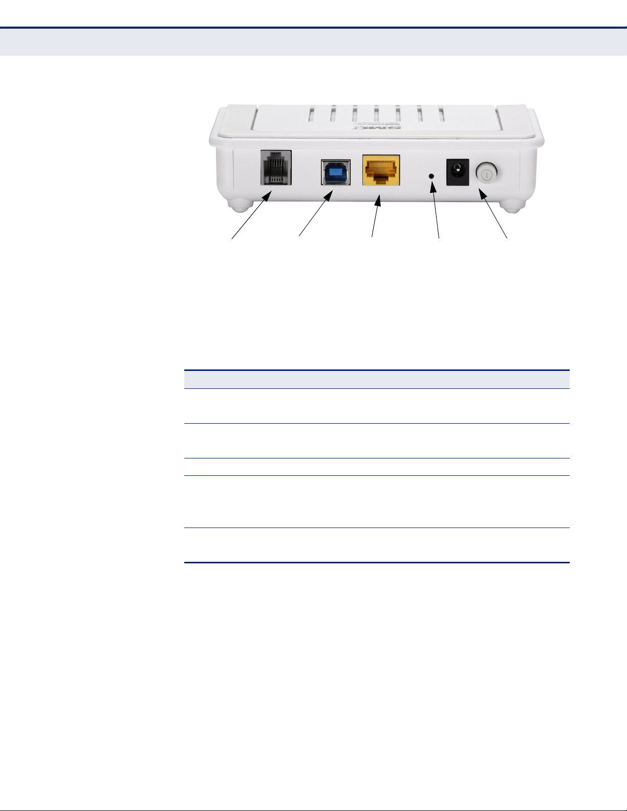
C
WAN Port
Power Socket and
On/Off Switch
USB Port
Ethernet Port Reset Button
HAPTER
1
| Introduction
Description of Hardware
Figure 2: Rear Panel
The ADSL Gateway Router includes key system and port indicators that
simplify installation and network troubleshooting. The LEDs, which are
located on the top of the unit for easy viewing, are described in the
following table.
Table 1: LED Display Indicators
LED Status Description
Power On Green The router is being supplied with power.
Off The router is not receiving power.
Link On Green The DSL Line port has a link with the service provider.
Blinking Green The DSL line is training.
Data Blinking Green Data is crossing DSL link.
Ethernet On Green Ethernet port has a valid link with attached device.
Blinking Green Data is being transmitted or received on the port.
Off Ethernet port has no link with an attached device.
USB On Green The USB port has a valid connection.
Off The USB port has no connection.
– 21 –
Page 22

C
HAPTER
1
| Introduction
Description of Hardware
POWER CONNECTOR The ADSL Gateway Router must be powered with its supplied power
adapter. Failure to do so results in voiding of any warrantly supplied with
the product. The power adapter automatically adjusts to any voltage
between 100~240 volts at 50 or 60 Hz, and supplies 12 volts DC power to
the unit. No voltage range settings are required.
POWER BUTTON The ADSL Gateway Router has a power button. When the AC power
adapter is attached and connected to a power source, the power button
must be depressed to power on the unit.
RESET BUTTON This button is used to restore the factory default configuration. If you press
and hold down the button for 3 seconds or more, any configuration
changes you may have made are removed, and the factory default
configuration is restored to the unit.
– 22 –
Page 23

2 INSTALLING THE ROUTER
Before installing the ADSL Gateway Router, verify that you have all the
items listed in “Package Contents.” If any items are missing or damaged,
contact your local distributor. Also, be sure you have all the necessary tools
and cabling before installing the router.
PACKAGE CONTENTS
After unpacking the ADSL Gateway Router, check the contents of the box to
be sure that you have received the following components:
◆ Barricade ADSL Gateway Router, SMC7901BRA5
◆ RJ-45 Category 5 network cable
◆ ADSL splitter
◆ AC power adapter
◆ Quick Installation Guide
◆ Documentation CD
◆ SMC warranty information card
Please inform your dealer if there are any incorrect, missing, or damaged
parts. If possible, retain the carton, including the original packing materials
in case there is a need to return the unit for repair.
SYSTEM REQUIREMENTS
Before you start installing the router, make sure you can provide the right
operating environment. See the following installation requirements:
◆ A PC or Macintosh with a 10/100 Mbps Ethernet adapter card installed.
◆ For Internet access, the computer must be configured for TCP/IP.
Or, a Windows PC with an available USB port.
◆ Power requirements: 12 VDC using the included AC power adapter.
Make sure that a properly grounded power outlet is within 1.8 m (6 ft)
of the router.
– 23 –
Page 24
CABLE CONNECTIONS
Category 5
UTP Cable
Computer
AC Power
Adapter
AC Power Outlet
Telephone Wall Jack
Standard
Telephone
Cable
Splitter
Telephone
C
HAPTER
2
| Installing the Router
Cable Connections
◆ The router should be located in a cool dry place, with at least
5 cm (2 in.) of space on all sides for ventilation.
◆ Place the router out of direct sunlight, and away from heat sources or
areas with a high amount of electromagnetic interference. The
temperature and humidity should be within the ranges listed in the
specifications.
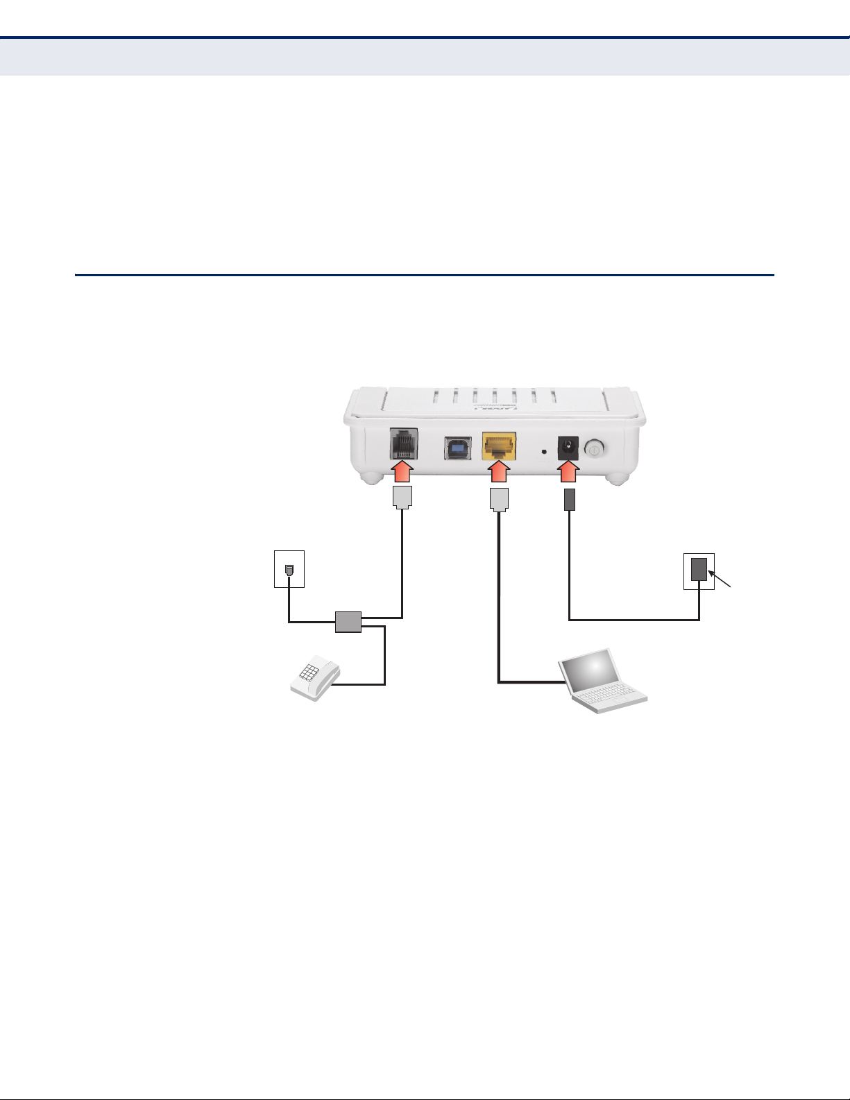
The ADSL Gateway Router needs to be connected to the DSL telephone line
from the service provider, and to a computer or LAN switch.
Figure 3: Connecting the Router
To install the router, follow these steps:
1. Using standard telephone cable, connect the Line port on the included
ADSL splitter to the RJ-11 telephone wall jack providing the ADSL
service.
2. Using standard telephone cable, connect the Modem port on the
included ADSL splitter to the RJ-11 Line port on the ADSL Gateway
Router.
3. The Phone port on the ADSL splitter can be connected to a standard
telephone set using telephone cable.
– 24 –
Page 25

C
HAPTER
2
| Installing the Router
Powering On
4. Connect one end of the included Ethernet cable to the Ethernet port on
the ADSL Gateway Router, and the other end to a PC’s RJ-45 network
port. Alternatively, you can connect the Ethernet port to a LAN switch.
C
AUTION
twisted-pair cables with RJ-45 connectors that conform to FCC standards.
N
OTE
switch), you can use either straight-through or crossover cabling. (Refer to
“Cables and Pinouts” on page 118 for a description of cable types.)
N
OTE
Ethernet port does not exceed 100 meters (328 feet).
:
Do not plug a phone jack connector into any RJ-45 port. Use only
:
When connecting to any network device (such as a PC, hub or
:
Make sure the twisted-pair Ethernet cable connected to the router’s
5. (Optional) For Windows PCs, you can also connect a USB cable from the
router’s USB port directly to the PC. Then install the USB driver that is
on the included CD.
POWERING ON
Plug the power adapter cord into the DC 12V power socket on the router,
and then plug the power adapter directly into a power outlet. Check the
LED marked Power on the top of the unit to be sure it is on. If the Power
indicator does not light up, refer to “Troubleshooting” on page 112.
If the router is properly configured, it will take about 30 seconds to
establish a connection with the ADSL service provider after powering up.
During this time the Link indicator will blink during synchronization. After
the ADSL connection has been established, the Link indicator will stay on.
CONFIGURING THE TCP/IP PROTOCOLS
To connect the router to a computer through its Ethernet port, the
computer must have an Ethernet network adapter card installed, and be
configured for the TCP/IP protocol. Your service provider will configure
TCP/IP for client computers automatically using a networking technology
known as Dynamic Host Configuration Protocol (DHCP).
Carry out the following steps to check that the computer’s Ethernet port is
correctly configured for DHCP.
WINDOWS 95/98/NT
1. Click “Start/Settings/Control Panel.”
2. Click the “Network” icon.
– 25 –
Page 26

C
HAPTER
2
| Installing the Router
Configuring the TCP/IP Protocols
3. For Windows NT, click the “Protocols” tab.
4. Select “TCP/IP” from the list of network protocols; this may include
details of adapters installed in your computer.
5. Click “Properties.”
6. Check the option “Obtain an IP Address.”
WINDOWS 2000
1. Click “Start/Settings/Network/Dial-up Connections.”
2. Click “Local Area Connections.”
3. Select “TCP/IP” from the list of network protocols.
4. Click on “Properties.”
5. Select the option “Obtain an IP Address.”
WINDOWS XP
1. Click “Start/Control Panel/Network Connections.”
2. Right-click the “Local Area Connection” icon for the adapter you want to
configure.
3. Highlight “Internet Protocol (TCP/IP).”
4. Click on “Properties.”
5. Select the option “Obtain an IP address automatically” and “Obtain DNS
server address automatically.”
WINDOWS VISTA
1. Click Start/Control Panel.
2. Double-click “Network and Sharing Center.”
3. Click “View status.”
4. Click “Properties.” If the “User Account Control” window appears, click
“Continue.”
5. Highlight “Internet Protocol Version 6 (TCP/IPv6)” or “Internet Protocol
Version 4 (TCP/IPv4),” and click “Properties.”
6. Select the option “Obtain an IP address automatically” and “Obtain DNS
server address automatically.”
MAC OS
1. Pull down the Apple Menu. Click “Control Panels” and select “TCP/IP.”
– 26 –
Page 27

C
HAPTER
2
| Installing the Router
Configuring the TCP/IP Protocols
2. In the TCP/IP dialog box, verify that “Ethernet” is selected in the
“Connect Via:” field.
3. If “Using DHCP Server” is already selected in the “Configure” field, your
computer is already configured for DHCP. Otherwise, select “Using
DHCP Server” in the “Configure” field and close the window.
4. Another box will appear asking whether you want to save your TCP/IP
settings. Click “Save.”
5. Your service provider will now be able to automatically assign an IP
address to your computer.
– 27 –
Page 28

S
ECTION
WEB CONFIGURATION
This section describes the basic settings required to access the web
management interface and provides details on configuring the Gateway.
This section includes these chapters:
◆ “System Configuration” on page 29
◆ “Device Information” on page 37
◆ “Advanced Setup” on page 47
◆ “Wi-Fi Configuration” on page 109
II
◆ “Diagnostics” on page 96
◆ “Administration Settings” on page 103
– 28 –
Page 29
3 SYSTEM CONFIGURATION
USING THE WEB INTERFACE
The router provides a web-based management interface for configuring
device features and viewing statistics to monitor network activity. This
interface can be accessed by any computer on the network using a
standard web browser (such as Internet Explorer 5.0, Netscape 6.2, Mozilla
Firefox 2.0, or above).
To make an initial connection to the management interface, connect a PC
to one of the router’s LAN ports. Set your PC with a static address within
the same subnet as that used by the router (that is, 192.168.2.x with the
subnet mask 255.255.255.0).
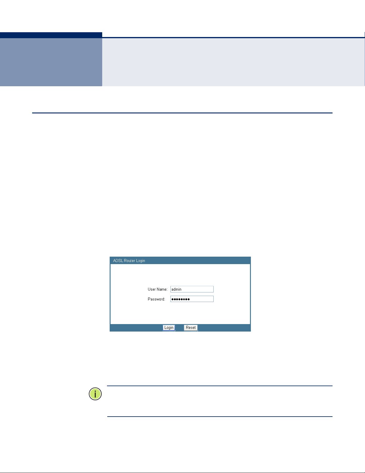
To access the configuration menu, follow these steps:
1. Use your web browser to connect to the management interface using
the default IP address of 192.168.2.1.
Figure 4: Web Login
2. Log in to the router’s management interface using this account:
User name: admin
Password: smcadmin
N
OTE
:
It is strongly recommended to change the default password the first
time you access the web interface. For information on changing the
password, see “Password Setup” on page 106.
– 29 –
Page 30
C
HAPTER
3
| System Configuration
Using the Web Interface
HOME PAGE When your web browser connects with the router’s web agent, the home
page is displayed as shown below. Basic information can be viewed using
the Status menu. To carry out detailed configuration tasks, use the other
menu items.
Figure 5: Home Page
The main menu is displayed on the left side of the screen. Click on any of
these items to open the sub-menu list. The information in this chapter is
organized to reflect the structure of the web management screens for easy
reference. The configuration pages include the options listed in the table
below. For details on configuring each feature, refer to the corresponding
page number.
Table 2: Configuration Menu
Menu Description Page
Wizard Starts the setup wizard 33
Status
System Shows hardware/software version numbers, DSL
connection status, and Internet connection settings
LAN Shows the LAN IP and DHCP server settings 38
WAN Shows WAN interface functional status (including
connection mode – single or multiple service, IGMP), and
connection status
Port Mapping Shows the port mapping settings 40
Statistics
Statistics Shows the network traffic statistics 41
DSL Statistics Shows the ADSL line statistics 42
37
39
ARP Shows entries in the ARP table 43
LAN Interface
LAN Interface Configures the LAN management interface, including IP
address, and IGMP snooping on LAN side
– 30 –
46
Page 31

C
HAPTER
3
| System Configuration
Using the Web Interface
Table 2: Configuration Menu (Continued)
Menu Description Page
DHCP Config
DHCP Mode Sets DHCP server and DHCP relay settings 47
Static IP Configures static DHCP assignments 51
WAN Interface
Channel Config Configures the DSL channel settings 53
ATM Settings Configures DSL ATM settings 55
ADSL Settings Configures ADSL settings 57
Services
DNS
DNS Server Configures DNS server settings 60
Dynamic DNS Configures DDNS settings 61
Access Control List
ACL Config Configures ACLs for LAN or WAN interfaces 63
IP/Port Filtering Configures IP filtering settings 66
NAT/NAPT
Virtual Server Configures the virtual server forwarding table 68
NAT Exclude IP Configures excluded IPs on the WAN interface 70
NAT Forwarding Configures forwarding for access to local servers 70
NAT ALG and PassThrough
NAT Port Trigger Restricts Internet access for specific ports 72
FTP ALG
Configuration
NAT IP Mapping Configures IP address mapping for NAT 73
IP QoS Configures IP-based QoS settings 74
MAC Filtering Configures MAC address filtering 76
DMZ Configures DMZ settings 77
URL Block Sets URL key words to block 78
Software Forbidden Blocks Internet access for specific software 79
DoS Setting Configures denial-of-service settings 80
IGMP Proxy Configures IGMP Proxy settings for multicast traffic 82
RIP Configures Routing Information Protocol settings 84
ARP Binding Configures Address Resolution Protocol binding 85
Configures NAT passthrough for specific application
protocols
Configures FTP server and client ports 73
71
Advance
Bridge Setting Configures aging time and Spanning Tree settings 87
Log Setting Configures system log settings 88
Routing Configures static routing 89
– 31 –
Page 32

C
HAPTER
3
| System Configuration
Using the Web Interface
Table 2: Configuration Menu (Continued)
Menu Description Page
UPnP Enables UPnP for the WAN interface 91
SNMP Configures SNMP settings 92
System Time Configures NTP time server settings 93
Others Configures Half Bridge settings 94
Port Mapping Maps LAN ports to WAN interfaces 95
Diagnostic
Diag-Test Runs diagnostic tests for the ADSL link 97
Ping Sends Ping echo requests to other devices 98
Traceroute Checks routes to other deives 99
ADSL Runs ADSL diagnostic tone tests 101
Admin
Commit/Reboot Reboots the unit and/or restores factory defaults 104
Backup/Restore Backs up or restores configuration settings 105
Password Setup Changes the web access passwords 106
Upgrade Firmware Upgrades the unit’s software version 107
Configure TR-069 Configures parameters for establishing a connection
between the router and an auto-configuration server
108
– 32 –
Page 33

SETUP WIZARD
C
HAPTER
3
| System Configuration
Setup Wizard
The Wizard is designed to help you configure the basic settings required to
get the ADSL Gateway Router up and running. Click “Wizard” in the main
menu to get started.
STEP 1 - GETTING
After reading the wizard welcome message, click Next to continue.
STARTED
Figure 6: Wizard Step 1 - Getting Started
STEP 2 - TIME ZONE Configure a Network Time Protocol (NTP) server to poll for time updates.
To synchronize the router with an NTP server, specify the IP address of a
public time server, select your local time zone, and click Next.
Figure 7: Wizard Step 2 - Time Zone Configuration
– 33 –
Page 34

C
HAPTER
3
| System Configuration
Setup Wizard
The following items are displayed on this page:
◆ Status – Enables or disables time synchronization with external
servers.
◆ Server IP – Specifies the IP address of a public NTP time server on the
Internet.
◆ Interval – Specifies the time interval for polling the NTP server.
◆ Time Zone – A drop-down box provides access to predefined time
zones. Each choice indicates it’s offset from GMT and lists at least one
major city or commonly known zone name covered by the time zone.
STEP 3 - ADSL
SETTINGS
The third page of the wizard configures the ADSL country settings, Internet
service provider, protocol, connection type and username and password.
Figure 8: Wizard Step 3 - ADSL Settings
The following items are displayed on the first page of the Wizard:
◆ Country — Choose your country of operation from the drop down
menu. If your country is not listed, contact your service provider for
detailed settings.
◆ Internet Service Provider — The chosen country will determine the
list of available Internet Service Providers. Choose the service provider
with which you have a contract.
– 34 –
Page 35

C
HAPTER
3
| System Configuration
Setup Wizard
◆ Protocol — The protocol used will be specified by your service
provider. Choose from the following options:
■
PPPoE — Point-to-Point Protocol over Ethernet (PPPoE).
■
PPPoA — Point-to-Point Protocol over Asynchronous Transfer Mode
(PPPoA).
■
1483 MER : DHCP — 1483 MER is an RFC standard MAC
Encapsulated Routing protocol.
■
1483 MER : Static IP — 1483 MER is an RFC standard MAC
Encapsulated Routing protocol.
■
1483 Bridged — The Bridged RFC 1483 Encapsulated Traffic over
ATM feature allows you to send bridged RFC 1483 encapsulated
packets over ATM switched virtual circuits (SVCs).
■
1483 Routed — Allows you to send routed RFC 1483 encapsulated
packets over ATM switched virtual circuits (SVCs).
■
IPoA — Dynamic IP over ATM (IPoA).
◆ Connection Type — Your connection type will also be specified by your
service provider. Choose from the following options:
■
VC-Mux — Virtual circuit multiplexing (VC-Mux).
■
LLC — Logical Link Control (LLC).
◆ VPI — The ATM Virtual Path Identifier. (Range: 0-255)
◆ VCI — The ATM Virtual Channel Identifier. (Range: 32-65535)
◆ Username — Enter the username provided by your service provider.
◆ Password — Enter the password provided by your service provider.
◆ Confirm Password — Re-enter your password.
– 35 –
Page 36

C
HAPTER
3
| System Configuration
Setup Wizard
STEP 4 -
CONFIGURATION
SAVING
The final step in the setup wizard saves the configuration changes. Click
Finish to complete the wizard, then click Save.
Figure 9: Wizard Step 3 - Configuration Saving
– 36 –
Page 37

4 DEVICE INFORMATION
The Status pages display information on hardware/software versions, LAN
and WAN connection status, statistics, and the ARP table.
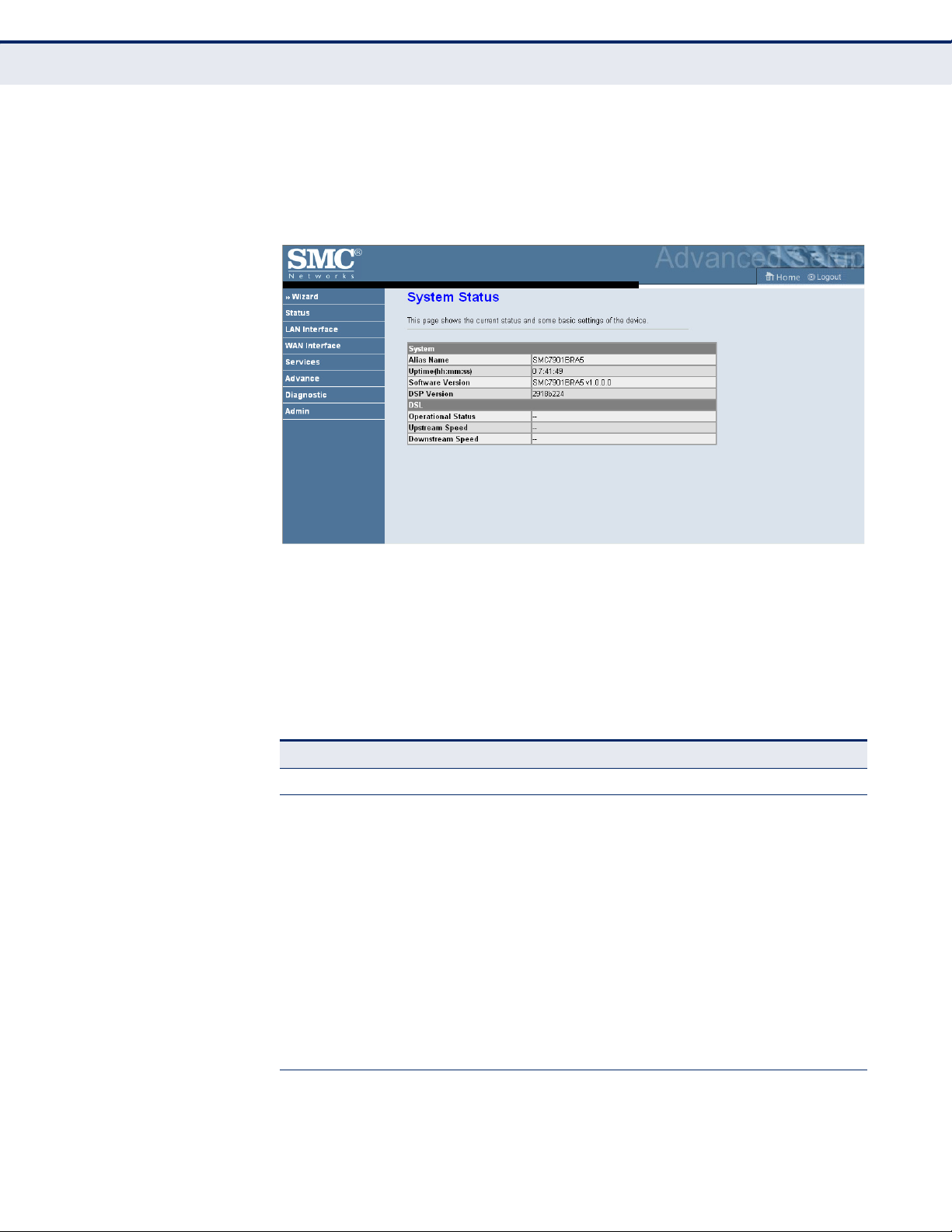
SYSTEM STATUS
The System Status page displays the hardware and software versions, and
the WAN connection status and speed.
Click Status, System.
Figure 10: System Status
The following items are displayed on this page:
SYSTEM:
◆ Alias Name – An alias for the ADSL Router, enabling the device to be
uniquely identified on the network.
◆ Uptime – The length of time in minutes that the unit has been powered
on.
◆ Software Version – The current version of firmware running on the
unit.
◆ DSP Version – The current hardware version of the digital signal
processor (DSP).
– 37 –
Page 38

LAN STATUS
C
HAPTER
4
| Device Information
LAN Status
DSL:
◆ Operational Status – Displays the status of the DSL connection.
◆ Upstream Speed – The current upload speed of the DSL connection.
◆ Downstream Speed – The current download speed of the DSL
connection.
The ADSL Router LAN window displays basic LAN port settings including
DHCP information.
Figure 11: Status - LAN
The following items are displayed on this page:
LAN STATUS
Displays the basic information of the LAN port.
◆ IP Address — Displays an IP address for local area connection to the
ADSL Router.
◆ Subnet Mask — Displays the local subnet mask.
◆ DHCP Server — Displays whether the DHCP server has been enabled
or not.
◆ MAC Address — Displays the physical layer address of the LAN port.
DHCP CLIENT TABLE
Displays information on the DHCP configuration and lease time.
◆ Name — Displays the name of the client device.
◆ IP Address — Displays the DHCP Client IP address.
– 38 –
Page 39

WAN STATUS
C
HAPTER
4
| Device Information
WAN Status
◆ MAC Address — Displays the physical layer address of the DHCP
Client.
◆ Expiry(s) — Displays the duration of the lease time.
◆ Type — Indicates if the entry is dynamic or static.
The ADSL Router WAN window displays basic WAN port settings.
Figure 12: Status - WAN
The following items are displayed on this page:
◆ Interface — Displays the interface identifier.
◆ VPI/VCI — Displays the ATM channel identifiers.
◆ Encapsulation — Displays the encapsulation type chosen, either LLC
to VX-Mux.
◆ Default Route — Dipslays if a default route has been enabled.
◆ Protocol — Displays the protocol used for transmission of data packets
◆ IP Address — Displays the local IP address of the WAN port.
◆ Default Gateway — Displays the network route, or gateway used by
the unit when no other known route exists for a given IP packet's
destination address.
◆ Status — Specifies the status of the interface.
◆ DNS Servers — Specifies the IP addresses of DNS servers.
– 39 –
Page 40

PORT MAPPING
C
HAPTER
4
| Device Information
Port Mapping
The Port Mapping status shows the mapping of WAN and LAN interfaces to
specific groups.
Figure 13: Status - Port Mapping
The following items are displayed on this page:
◆ Status — Indicates if port mapping is enabled or disabled.
◆ Select — Indicates the group identification.
◆ Interfaces — Specifies the WAN and LAN interfaces in the group.
◆ Status — Indicates if the group mapping is enabled.
– 40 –
Page 41

TRAFFIC STATISTICS
C
HAPTER
4
| Device Information
Traffic Statistics
The ADSL Router Traffic Statistics - Interfaces window displays received
and transmitted packet statistics for all interfaces on the ADSL Router.
Figure 14: Status - Traffic Statistics
The following items are displayed on this page:
◆ Interface — Displays the interface on which traffic is being monitored.
◆ Rx Packet — Displays the total number of packets received by the
specified interface.
◆ Rx Error — Displays the total number of packet errors received by the
specified interface, if any.
◆ Rx Drop — Displays the total number of received packets dropped by
the specified interface.
◆ Tx Packet — Displays the total number of packets transmitted by the
specifed interface.
◆ Tx Error — Displays the total number of packet errors occured during
transmission by the specified interface.
◆ Tx Drop — Displays the total number of packets transmitted but
dropped by the specified interface.
◆ Refresh — Updates the statistical table for all interfaces.
– 41 –
Page 42

DSL STATISTICS
C
HAPTER
4
| Device Information
DSL Statistics
The ADSL Router DSL Statistics window displays received and transmitted
packet statistics for all interfaces on the ADSL Router.
Figure 15: Status - DSL Statistics
The following items are displayed on this page:
◆ ADSL Status — Displays the ADSL connection status (“activating”,
“up” or null).
◆ ADSL Mode — Displays the connection mode for the ADSL Router,
which is fixed at ADSL2+.
◆ Upstream — Displays the actual payload carried on the upstream
channels.
◆ Downstream — Displays the actual payload carried on the
downstream channels.
◆ Attentuation Downstream/Upstream (db) — Displays the amount
of attenuation in signal strength due to conductive losses in
transmission medium. Attenuation affects the propagation of waves
and signals in electrical circuits, expressed in decibels (dB).
– 42 –
Page 43

C
HAPTER
4
| Device Information
ARP Table
◆ SNR Margin Downstream/Upstream (db) — Displays the current
signal-to-noise margin expressed in decibels (dB). SNR is the ratio of
signal power to the noise power corrupting the signal.
◆ Vendor ID – The vendor name of the digital signal processor (DSP).
◆ DSP Version – The current hardware version of the digital signal
processor (DSP).
◆ CRC Errors — Displays the CRC (cyclic redunancy check) - a type of
function that takes as input a data stream of any length, and produces
as output a value of a certain space, commonly a 32-bit integer.
◆ Upstream/Downstream BER – The the rate at which bits in the data
stream that have been altered by noise.
◆ Up/Down Output Power — Displays the upstream/downstream
power level employed for ADSL port filtering.
◆ ES — Displays the total error seconds, the number of second intervals
during which there was one or more CRC anomalies, or one or more
Loss of Signal (LOS) or Loss of Framing (LOF) defects.
ARP TABLE
◆ SES — Displays the total severly errored seconds. The number of
second intervals containing 18 or more CRC-8 anomalies, one or more
Loss of Signal (LOS) defects, one or more Severely Errored Frame
(SEF) defects, or one or more Loss of Power (LPR) defects.
◆ UAS — Displays the total unavailable errored seconds, the number of
seconds during which the ADSL transceiver is powered up but not
available.
◆ ADSL Retrain — Retrains the DSL line.
The ARP page displays IP address to MAC address mapping entries
determined by the Address Resolution Protocol.
Figure 16: Status - ARP Table
– 43 –
Page 44

C
HAPTER
4
| Device Information
ARP Table
The following items are displayed on this page:
◆ IP Address — IP address of a local entry in the cache.
◆ MAC Address — MAC address mapped to the corresponding IP
address.
◆ Refresh — Sends a request to update the current parameters.
– 44 –
Page 45

5 LAN SETTINGS
This chapter describes LAN configuration on the ADSL Router.
You can use the web browser interface to access IP addressing only if the
ADSL Router already has an IP address that is reachable through your
network.
◆ “LAN Interface” on page 46
◆ “DHCP Settings” on page 47
– 45 –
Page 46

LAN INTERFACE
C
HAPTER
5
| LAN Settings
LAN Interface
By default, the ADSL Router is configured with the IP address 192.168.2.1,
subnet mask 255.255.255.0 and a default gateway of 192.168.2.1.
Figure 17: LAN Configuration
The following items are displayed on this page:
◆ Interface Name — Displays the name assigned to the interface.
◆ IP Address — Specifies an IP address for management of the ADSL
Router. Valid IP addresses consist of four decimal numbers, 0 to 255,
separated by periods. (Default: 192.168.2.1.)
◆ Subnet Mask — Indicates the local subnet mask.
(Default: 255.255.255.0)
– 46 –
Page 47

DHCP SETTINGS
C
HAPTER
5
| LAN Settings
DHCP Settings
◆ Secondary IP Address — Specifies a secondary IP address for
management of the unit.
◆ IGMP Snooping — Enables Internet Group Management Protocol
(IGMP) multicast filtering.
◆ LAN Port — Selects the LAN port.
◆ Link Speed/Duplex Mode — Selects the port speed and duplex
mode, or sets the port for auto-negotiation.
◆ MAC Address Control — Filters out traffic with source MAC addresses
not configured in the table. For devices that need Internet access
through the LAN port, enter the MAC address and click Add.
The ADSL Router includes a Dynamic Host Configuration Protocol (DHCP)
server that can assign temporary IP addresses to any attached host
requesting the service, as well as a DHCP relay serivce that will route the
DHCP service to other subnets than that of the unit.
DHCP DISABLED By selecting “None,” you can disable DHCP on the ADSL Router.
Figure 18: DHCP Disabled
The following items are displayed on this page:
◆ DHCP Mode — When set to “None,” disables DHCP on the unit.
– 47 –
Page 48

C
HAPTER
5
| LAN Settings
DHCP Settings
DHCP RELAY Dynamic Host Configuration Protocol (DHCP) can dynamically allocate an
IP address and other configuration information to network clients that
broadcast a request. To receive the broadcast request, the DHCP server
would normally have to be on the same subnet as the client. However,
when the access point’s DHCP relay agent is enabled, received client
requests can be forwarded directly by the access point to a known DHCP
server on another subnet. Responses from the DHCP server are returned to
the access point, which then broadcasts them back to clients.
Figure 19: DHCP Relay
The following items are displayed on this page:
◆ DHCP Mode — When set to “DHCP Relay,” enables routing of the DHCP
service to units on a different subnet.
◆ Relay Server — Enter the address of the DHCP server for routing to
other units.
– 48 –
Page 49

C
HAPTER
5
| LAN Settings
DHCP Settings
DHCP SERVER The unit can support up to 253 local clients. Addresses are assigned to
clients from a common address pool configured on the unit. Configure an
address pool by specifying start and end IP addresses. Be sure not to
include the unit's IP address in the address pool range.
Figure 20: DHCP Server
The following items are displayed on this page:
◆ LAN IP Address — Displays the LAN IP address for management of
the ADSL Router. (Default: 192.168.2.1.)
◆ Subnet Mask — Displays the local subnet mask.
(Default: 255.255.255.0)
◆ DHCP Mode — When set to “DHCP Server,” enables the ADSL Router to
act as a DHCP server.
◆ Interface — Selects either the RJ-45 LAN port, or the USB port.
◆ IP Pool Range — Configures the IP address pool for the DHCP server
and determines how many IP addresses can be assigned.
N
OTE
:
Do not enter the ADSL Router’s LAN IP address as part of the IP Pool
range.
◆ Show Client — Displays the current DHCP client table.
– 49 –
Page 50

C
HAPTER
5
| LAN Settings
DHCP Settings
◆ Default Gateway — Specifies the gateway address through which
traffic is routed from. Usually the LAN IP address of the ADSL Router
◆ MAX Lease Time — Select a time limit for the use of an IP address
from the IP pool. When the time limit expires, the client has to request
a new IP address. The lease time is expressed in seconds.
(Default: 86400 seconds; Range: 60~86400 seconds; -1 indicates an
infinite lease time)
◆ Domain Name — Specifies the unique name used to identify the ADSL
Router on the network.
◆ DNS Servers — Sets up to three domain name server IP addresses.
◆ Set VendorClass IP Range — Click on this option to assign IP
address ranges to specific device types.
■
Device Name — Describes the device type.
■
Start/End Address — Specifies the IP addresses from the DHCP IP
pool to assign to this device type.
■
Router Address — Specifies a default router IP address to use for
traffic from this device.
■
Option 60 — Specifies the DHCP Option 60 vendor class identifier
that indicates the device type.
Figure 21: Device IP Range Table
– 50 –
Page 51

C
HAPTER
5
| LAN Settings
DHCP Settings
DHCP STATIC IP Assigns a physical MAC address to the DHCP pool by mapping it to a
corresponding IP address.
Figure 22: DHCP Static IP Assignment
The following items are displayed on this page:
◆ IP Address — Enter the IP address from the DHCP address pool to
assign to the specified MAC address.
◆ MAC Address — Enter the MAC address to be assigned to a static IP
address from the DHCP address pool.
◆ Add — Selecting this option enters the mapped MAC address and IP
address into the DHCP Static IP Table.
◆ Delete Selected — Once you select and entry in the table by clicking
its corresponding radio button, this option deletes the entry.
◆ Reset — Clears the IP and MAC address fields.
– 51 –
Page 52

6 WAN SETTINGS
This chapter describes WAN configuration on the ADSL Router. The WAN
pages are used to configure standard WAN services, including VPI, VCI,
encapsulation, service type (PPPoE, IPoE, bridging), ATM settings and ADSL
settings. It includes the following sections:
◆ “Channel Configuration” on page 53
◆ “ATM Settings” on page 55
◆ “ADSL Settings” on page 57
– 52 –
Page 53

CHANNEL CONFIGURATION
The Channel Configuration page configures channel operation modes of the
ADSL Router.
Figure 23: WAN Configuration
C
HAPTER
6
| WAN Settings
Channel Configuration
The following items are displayed on this page:
◆ Default Route Selection – Enables the default route to be specified or
selected automatically.
◆ VPI (Virtual Path Identifier) – A grouping of virtual channels which
connect the same end-points, and which share a traffic allocation.
◆ VCI (Virtual Channel Identifier) – A specific virtual channel connecting
two end-points.
◆ Encapsulation:
■
LLC (Logical Link Control) – This encapsulation method allows
multiplexing of multiple protocols over a single ATM virtual
connection. In some cases, the LLC header is followed by a SNAP
header which uniquely identifies a routed or bridged protocol. (This
is the default packet encapsulation format used for carrying IP
datagrams over AAL5 ATM.)
– 53 –
Page 54

C
HAPTER
6
| WAN Settings
Channel Configuration
■
VC/MUX (Virtual Circuit Multiplexing) – When using this mode, the
communicating hosts agree on the high-level protocol for a given
circuit, which tends to reduce fragmentation overhead. This allows a
sender to pass each datagram directly to AAL5 for transfer, and
requires nothing to be sent besides the datagram and the AAL5
trailer. The chief disadvantage of this scheme is that a host must
create a separate virtual circuit for each high-level protocol if more
than one protocol is used. Because most carriers charge for each
virtual circuit, customers try to avoid using multiple circuits because
it adds unnecessary cost.
◆ Channel Mode — The protocol used on the channel, as specified by
the service provider. Choose from the following options:
■
1483 Bridged — The Bridged RFC 1483 Encapsulated Traffic over
ATM feature allows you to send bridged RFC 1483 encapsulated
packets over ATM switched virtual circuits (SVCs).
■
1483 MER — 1483 MER is an RFC standard MAC Encapsulated
Routing protocol.
■
PPPoE — Point-to-Point Protocol over Ethernet (PPPoE).
■
PPPoA — Point-to-Point Protocol over Asynchronous Transfer Mode
(PPPoA).
■
1483 Routed — Allows you to send routed RFC 1483 encapsulated
packets over ATM switched virtual circuits (SVCs).
■
IPoA — Dynamic IP over ATM (IPoA).
◆ Enabled NAPT — Enables Network Address Port Translation for the
channel.
◆ Enable IGMP — Enables IGMP for the channel.
◆ PPP Settings — Configures settings for PPPoE and PPPoA modes.
■
User Name — The PPP access user name provided by the ISP.
■
Password — The PPP access password provided by the ISP.
■
Type — Selects the connection type; Continuous, Connect on
Demand, or Manual.
■
Idle Time — The number of minutes you want to have elapsed
before your Internet access disconnects in Connect-on-Demand
mode.
◆ WAN IP Settings — Configures settings for 1483 MER, 1483 Routed,
and IPoA modes.
■
Type — Selects fixed IP or DHCP. When fixed IP is selected, enter
the local IP address, gateway, and subnet mask. When DHCP is
– 54 –
Page 55

ATM SETTINGS
C
HAPTER
6
| WAN Settings
ATM Settings
selected, the WAN interface IP address is assigned by the remote
DHCP server.
■
Local IP address — The IP address of the WAN interface provided
by the ISP.
■
Gateway — The IP address of the remote gateway router provided
by the ISP.
■
Netmask — The subnet mask for the local IP address.
■
Default Route — Enables or disables the default route IP address.
■
Unnmbered — Enables the IP unnumbered feature.
The ATM Settings page is used to configure the settings between your
ADSL Router and the remote ATM PVC switch, including connection mode
(single or multiple service over one connection), and packet level QoS.
The ATM Settings parameters form a Traffic Contract that informs the
network what type of traffic is to be transported and the performance
requirements of the traffic.
Figure 24: ATM Settings
The following items are displayed on this page:
◆ Select — Clicking the radio button associated with the connection
makes the parameters editable.
◆ VPI (Virtual Path Identifier) — Adds a VPI entry to the table. (Range:
0-255; Default: 0)
– 55 –
Page 56

C
HAPTER
6
| WAN Settings
ATM Settings
◆ VCI (Virtual Channel Identifier) — Adds a VCI entry to the table.
(Range: 32-65535; Default: 35)
◆ QoS — Selects packet level Quality of Service (QoS) for the connection.
Options are:
■
UBR (Unspecified Bitrate): Configures a PVC with a Peak Cell Rate
indicating the maximum number of ATM cells that can be sent in a
burst.
■
CBR (Constant Bitrate): Configures a PVC at a constant bit rate.
This option may be required for connections that depend on precise
clocking to ensure undistorted delivery.
■
nrt-VBR (non-realtime Variable Bitrate): Configures a PVC at a
non-realtime variable bit rate. This option may be used for
applications not sensitive to changes in available bandwidth, such
as data.
■
rt-VBR (realtime Variable Bitrate): Configures a PVC at a real-time
variable bit rate. This option may be used for applications that have
a lot of variance in required bandwidth, such as voice.
◆ PCR (Peak Cell Rate) — Configures the maximum allowable rate at
which cells can be transported along a connection in the ATM network.
The PCR is the determining factor in how often cells are sent in relation
to time in an effort to minimize jitter.
◆ CDVT (Cell Delay Variation Tolerance) — Configures the maximum
amount of jitter permissable.
◆ SCR (Sustainable Cell Rate) — Configures the average allowable, long-
term cell transfer rate on a specific connection.
◆ MBS (Maximum Burst Size) — Configures the maximum allowable
burst size of cells that can be transmitted contiguously on a particular
connection.
◆ Current ATM VC Table — The Current ATM VC Table lists the current
ATM settings configured on your ADSL Router. By selecting the
connection using the radio button associated with it you can edit the
connection parameters.
– 56 –
Page 57

ADSL SETTINGS
C
HAPTER
6
| WAN Settings
ADSL Settings
The ADSL Settings page configures the ADSL modulation type, ADSL2+
related parameters, capabilities and the ADSL tone mask.
Figure 25: ATM Settings
The following items can be enabled on this page:
◆ ADSL Modulation — ADSL Modulation refers to a frequency-division
multiplexing (FDM) scheme utilized as a digital multi-carrier
modulation method for DSL. A large number of closely-spaced
orthogonal sub-carriers are used to carry data. The data is divided into
several parallel data streams or channels, one for each sub-carrier.
Each sub-carrier is modulated with a conventional modulation scheme
(such as G.lite, ADSL2, etc. or more commonly ADSL2+).
■
G.lite — A standard that defines the more economical splitterless
ADSL connection that transmits data at up to 1.5 Mbps downstream
and 512 Kbps upstream. This ADSL option can be installed without
an on-site visit by the service provider.
■
G.dmt — A standard that defines full-rate ADSL, and utilizes
Discrete Multi-Tone (DMT) signaling to transmit data at up to 8
Mbps downstream and 640 Kbps upstream.
■
T1.413 — ANSI standard that defines the requirements for ADSL
for the interface between the telecommunications network and the
customer installation in terms of their interaction and electrical
characteristics. (The Gateway complies with Issue 2 of this
standard.)
– 57 –
Page 58

C
HAPTER
■
ADSL2 — This standard extends the capability of basic ADSL data
6
| WAN Settings
ADSL Settings
rates to 12 Mbit/s downstream and 3 Mbit/s upstream (with a
mandatory capability of ADSL2 transceivers of 8 Mbit/s downstream
and 800 Kbit/s upstream.
■
ADSL2+ — This standard extends the capability of basic ADSL data
rates to 24 Mbit/s downstream and 1.4 Mbit/s upstream depending
on the distance from the DSLAM to the customer's home.
◆ AnnexL Option — Annex L is an optional specification in the ITU-T
ADSL2 recomendation G.992.3 titled “Specific requirements for a Reach
Extended ADSL2 (READSL2) system operating in the frequency band
above POTS.” It is often referred to as Reach Extended ADSL2 or
READSL2. Once enabled AnnexL increases the range of DSL service,
enabling the link to work at a distance of 7 kilometers, or 23,000 feet.
◆ AnnexM Option — Annex M is an optional specification in ITU-T
recomendations G.992.3 (ADSL2) and G.992.5 (ADSL2+), also referred
to as ADSL2 M and ADSL2+ M. This specification extends the capability
of commonly deployed Annex A by more than doubling the number of
upstream bits.
Once enabled AnnexM increases upload speeds by the shifting the
upstream/downstream frequency split from 138 kHz up to 276 kHz,
allowing the maximum upstream bandwidth to be increased from 1.4
Mbit/s to 3.3 Mbit/s.
◆ ADSL Capability — ADSL Capability refers to means of manipulating
the bit loading of a connection to increase quality of signal or
transmission rate.
■
Bitswap — Enables bit swapping. Bit swapping is a way of
swapping the bit-loading of a noisy tone with another tone in the
symbol which is not as noisy. The bit loading from a specific tone
can be increased or decreased. In addition, the TX power can be
increased or decreased for a specific tone. However, there is no
change in the overall payload rate after the bit swap operation.
■
SRA — Enables seamless rate adaptation to set the optimal
transmission rate based on existing line conditions.
– 58 –
Page 59

7 SERVICES
The Advanced Configuration settings for the ADSL Router contain advanced
system management configuration settings such as DNS setup, routing
configuration, bridging, SNMP and TR-069 settings.
The following sections are contained in this chapter:
◆ “DNS Settings” on page 60
◆ “Access Control Lists” on page 63
◆ “IP/Port Filtering” on page 66
◆ “NAT/NAPT Settings” on page 68
◆ “Quality of Service” on page 74
◆ “MAC Filtering” on page 76
◆ “DMZ” on page 77
◆ “URL Blocking” on page 78
◆ “Software Forbidden” on page 79
◆ “DoS” on page 80
◆ “IGMP Proxy Configuration” on page 82
◆ “RIP Configuration” on page 84
◆ “ARP Binding Configuration” on page 85
– 59 –
Page 60

DNS SETTINGS
DNS SERVER The Domain Name Server (DNS) implements a human recognizable web
C
HAPTER
7
| Services
DNS Settings
Sets Domain Name Server (DNS) and Dynamic DNS settings.
address to a numerical IP address. DNS can be set automatically or
manually.
Figure 26: DNS Server Configuration
The following items are displayed on this page:
◆ Obtain DNS Automatically — The DNS server IP address is
automatically configured during dynamic IP assignment.
◆ Set DNS Manually — Allows the user to set up to three DNS server IP
addresses.
– 60 –
Page 61

C
HAPTER
7
| Services
DNS Settings
DDNS Dynamic DNS (DDNS) provides users on the Internet with a method to tie
a specific domain name to the unit’s dynamically assigned IP address.
DDNS allows your domain name to follow your IP address automatically by
changing your DNS records when your IP address changes.
The ADSL Router provides access to two DDNS service providers,
DynDns.org, and TZO. To set up an DDNS account, visit the websites of
these service providers at www.dyndns.org,or www.tzo.com.
Figure 27: DDNS DynDns
The following items are displayed on these pages:
◆ DDNS provider — Specify the DDNS provider from the drop down
menu. Options are: DynDns, or TZO. (Default: DynDns.org)
◆ Host Name — Specifies the prefix to identify your presence on the
DDNS server, either URL or IP address.
◆ Interface — Selects the WAN interface for the DDNS service.
◆ Enable — Enables DDNS. (Default: Enabled)
DYNDNS SETTINGS
The following parameters apply to the default DynDns setting.
◆ User Name — Specifies your username for the DDNS service.
◆ Password — Specifies your password for the DDNs service.
– 61 –
Page 62

C
HAPTER
7
| Services
DNS Settings
TZO
The following parameters apply to the TZO setting.
◆ Email — Specifies your contact email address for the DDNS service.
◆ Key — Specifes an encryption key for the DDNS service.
DYNAMIC DDNS TABLE
This table displays the configured servers in the DDNS setup.
◆ Select — Highlights an entry in the Dynamic DDNS Table.
◆ State — Displays the state of the server entry, enabled or disabled.
◆ Service — Displays the type of DDNS service.
◆ Host Name — Displays the URL or IP address of the DDNS service
provider.
◆ User Name — Displays the user name or contact email of the DDNS
user.
◆ Interface — The WAN interface for the DDNS service.
– 62 –
Page 63

ACCESS CONTROL LISTS
The ADSL Router supports Access Control Lists that filter IP addresses
allowed access on the unit's LAN and WAN interfaces. Only traffic from IP
addresses in the ACL table are allow access to the ADSL Router.
LAN ACLS When you select LAN for the ACL “direction,” you can configure ACLs that
apply to the LAN interfaces.
Figure 28: LAN ACL Configuration
C
HAPTER
7
| Services
Access Control Lists
The following items are displayed on this page:
◆ LAN ACL Switch — Enables LAN ACLs on the ADSL Router.
(Default: Disabled)
N
OTE
:
Do not enable ACLs without first configuring your host IP address in
the ACL table, otherwise you will not be able to access the unit.
◆ Apply Changes — Implements the ACL settings on the ADSL Router.
◆ IP Address — Specify a LAN IP address or range of addresses that are
allowed access to the ADSL Router.
◆ Services Allowed — Specifies services that are allowed access from
LAN interfaces, or allows “any.”
◆ Add — Adds the ACL to the ACL Table.
– 63 –
Page 64

C
HAPTER
7
| Services
Access Control Lists
CURRENT ACL TABLE
Lists the configured ACLs on the LAN ports.
◆ Select — The number of the entry in the table.
◆ Direction — Displays if the ACL is applied to a LAN or WAN interface.
◆ IP Address/Interface — Displays the allowed IP address or range.
◆ Service — Dispays the allowed service.
◆ Port — Displays the TCP/UDP port of the allowed service.
◆ Action — Click the button to remove the entry from the table.
WAN ACLS When you select WAN for the ACL “direction,” you can configure ACLs that
apply to WAN interfaces.
Figure 29: WAN ACL Configuration
The following items are displayed on this page:
◆ WAN Setting — Selects a WAN interface or IP address.
■
WAN Interface — Specifies a configured WAN interface for the
ACL.
■
IP Address — Specify a LAN IP address or range of addresses that
are allowed access to the ADSL Router.
◆ Services Allowed — Specifies services that are allowed access from
LAN interfaces, or allows “any.”
– 64 –
Page 65

C
HAPTER
7
| Services
Access Control Lists
◆ Add — Adds the ACL to the ACL Table.
CURRENT ACL TABLE
Lists the configured ACLs on the LAN ports.
◆ Select — The number of the entry in the table.
◆ Direction — Displays if the ACL is applied to a LAN or WAN interface.
◆ IP Address/Interface — Displays the allowed IP address or range.
◆ Service — Dispays the allowed service.
◆ Port — Displays the TCP/UDP port of the allowed service.
◆ Action — Click the button to remove the entry from the table.
– 65 –
Page 66

IP/PORT FILTERING
C
HAPTER
7
| Services
IP/Port Filtering
IP/Port filtering restricts connection parameters to limit the risk of intrusion
and defends against a wide array of common hacker attacks. IP/Port
filtering allows the unit to permit, deny or proxy traffic through its ports
and IP addresses.
Figure 30: IP/Port Filtering Settings
The following items are displayed on this page:
◆ Outgoing Default Action — Sets the default filtering action for
outgoing packets that do not match a rule in the filter table. (Default:
Permit, maximum 32 entries are allowed.)
◆ Incoming Default Action — Sets the default filtering action for
incoming packets that do not match a rule in the filter table. (Default:
Deny, maximum 32 entries are allowed.)
N
OTE
:
The default incoming action denies all packets from the WAN port.
◆ Rule Action — Specifies if traffic should be permitted or denied.
(Default: Permit)
◆ Protocol — Specifies the destination port type, TCP, UDP or ICMP.
(Default: TCP).
◆ Direction — Specifies the packet destination. (Default: Outgoing)
– 66 –
Page 67

C
HAPTER
7
| Services
IP/Port Filtering
◆ Source IP Address — Specifies the source IP address to block or allow
traffic from.
◆ Destination IP Address — Specifies the destination IP address to
block or allow traffic from.
◆ Subnet Mask — Specifies a subnet mask.
◆ Source Port — Specifies a range of ports to block traffic from the
specified LAN IP address.
◆ Destination Port — Specifies a range of ports to block traffic from the
specified LAN IP address from reaching.
◆ Apply Changes — Adds a newly configured packet filter that denies
forwarding in to the local area network to the list.
CURRENT FILTER TABLE
The Current Filter Table displays the configured IP addresses and ports that
are permitted or denied access to and from the ADSL Router.
◆ Rule — Displays if the specified traffic is allowed or denied.
◆ Protocol — Displays the destination port type.
◆ Source IP/Mask — Displays the source IP address.
◆ SPort — Displays the source port range.
◆ Dest IP/Mask — Displays the destination IP address.
◆ DPort — Displays the destination port range.
◆ State — Indicates if an entry is enabled.
◆ Direction — Displays the direction in which the rule has been applied.
◆ Action — Enables/disables or deletes the selected entry from the table.
– 67 –
Page 68

NAT/NAPT SETTINGS
C
HAPTER
Network Address Translation (NAT) is a standard method of mapping
multiple “internal” IP addresses to one “external” IP address on devices at
the edge of a network. For the router, the internal (local) IP addresses are
the IP addresses assigned to local PCs by the DHCP server, and the
external IP address is the IP address assigned to the specified WAN
interface.
The NAT function on the router enables the support of Virtual Servers, Port
Triggering, and other features.
Some applications, such as Internet gaming, videoconferencing, Internet
telephony and others, require multiple connections. These applications
may not work with Network Address Translation (NAT) enabled. If you need
to run applications that require multiple connections, use Port Triggering to
specify the additional public ports to be opened for each application.
Alternatively, you can open up a client to unrestricted two-way Internet
access by defining it as DMZ (demilitarized-zone) host.
7
| Services
NAT/NAPT Settings
VIRTUAL SERVERS Using the NAT Virtual Server feature, remote users can access different
servers on your local network using your single public IP address.
Remote users accessing services such as web or FTP at your local site
thorugh your public IP address, are redirected (mapped) to other local
server IP addresses and TCP/UDP port numbers. For example, if you set
Type/Public Port to TCP/80 (HTTP or web) and the Private IP/Port to
192.168.7.9/80, then all HTTP requests from outside users forwarded to
192.168.7.9 on port 80. Therefore, by just using your external IP address
provided by your ISP, Internet users can access the services they need at
the local addresses to which you redirect them.
The more common TCP service port numbers include: HTTP: 80, FTP: 21,
Telnet: 23, and POP3: 110. Up to 32 entries can be configured in the
Virtual Servers table.
– 68 –
Page 69

Figure 31: NAT — Virtual Servers
C
HAPTER
7
| Services
NAT/NAPT Settings
The following items are displayed on this page:
◆ Service Type – Sets a name to describe the virtual server service.
■
Usual Service Name – Select a name from the list of common
applications.
■
User-defined Service Name – Set a custom name to describe the
service.
◆ Protocol – Specifies the port type. (Options: TCP or UDP; Default:
TCP)
◆ WAN Setting – Selects a WAN interface or IP address. Depending on
the selection, either the WAN Interface or WAN IP Address setting
displays.
■
WAN Interface – Select the WAN interface for the virtual server.
■
WAN IP Address – Specify the WAN IP address for the virtual
server.
◆ WAN Port – Specifies the public TCP/UDP port number, or port range,
used for the service on the WAN interface. (Range: 1-65535)
◆ LAN Open Port – Specifies the TCP/UDP port number, or port range,
used on the local server for the service. (Range: 1-65535)
◆ LAN IP Address – The IP address of the server on the local Ethernet
network. The specified address must be in the same subnet as the
router and its DHCP server address pool. (Range: 192.168.2.2 to
192.168.2.254)
– 69 –
Page 70

C
HAPTER
7
| Services
NAT/NAPT Settings
NAT EXCLUDE IP You can use the Exclude IP feature to block an IP address or range of IP
addresses from accessing WAN interfaces.
Figure 32: NAT — Exclude IP
The following items are displayed on this page:
◆ Interface – Select the WAN interface for the Exclude IP service.
◆ IP Range – Specifies an IP address range to block on the WAN
interface.
NAT FORWARDING Forwarding allows an external user to reach a private IP address (inside a
LAN) from the outside through a NAT-enabled router.
Figure 33: NAT Forwarding Settings
The following items are displayed on this page:
◆ Local IP Address — Specifies the IP address of a computer on the
local network.
– 70 –
Page 71

C
HAPTER
7
| Services
NAT/NAPT Settings
◆ Remote IP Address — Specifies the source IP address on the WAN to
allow access from. Leaving this parameter blank allows access from all
traffic.
◆ Enable — Checking this box activates the parameters configurated
once added to the Current NAT Port Forwarding Table.
(Default: Enabled)
NAT ALG AND PASS-
THROUGH
Application Layer Gateway (ALG) and passthrough is a useful feature when
a host computer or server on the Local Area Network must be accessible
from the Internet using specific protocols. This can be necessary with
certain software applications that do not function reliably through Network
Address Translation.
Figure 34: NAT ALG and Pass-Through
The following items are displayed on this page:
◆ IPSec Pass Through — Enables IPsec passthrough.
(Default: Enabled)
◆ L2TP Pass Through — Enables L2TP passthrough. (default: Enabled)
◆ PPTP Pass Through — Enables PPTP passthrough. (Default: Enabled)
◆ FTP — Enables FTP passthrough. (Default: Enabled)
◆ H.323 — Enables H.323 (Windows Netmeeting) passthrough.
(Default: Enabled)
◆ SIP — Enables SIP passthrough. (Default: Enabled)
◆ RTSP — Enables RTSP passthrough. (Default: Enabled)
◆ ICQ — Enables ICQ passthrough. (Default: Enabled)
– 71 –
Page 72

C
HAPTER
7
| Services
NAT/NAPT Settings
◆ MSN — Enables MSN passthrough. (Default: Enabled)
NAT PORT TRIGGER Port triggering is a way to automate port forwarding in which outbound
traffic on predetermined ports (“triggering ports”) causes inbound traffic to
specific incoming ports to be dynamically forwarded to the initiating host
while the outbound ports are in use.
Figure 35: NAT — Port Trigger
The following items are displayed on this page:
◆ Port Trigger – Enables the feature. (Default: Disabled)
◆ Application Type – Select a name from the list of common
applications, or set a custom name to describe the service.
◆ Start/End Match Port — Specifies the trigger port range. (Range: 1-
65535)
◆ Trigger Protocol — Specifies the trigger port type used, TCP, UDP, or
both.
◆ Start/End Relate Port — Specifies the public port range. (Range: 1-
65535).
◆ Open Protocol — Specifies the public port type used, TCP, UDP, or
both.
◆ NAT Type — Specifies outgoing or incoming traffic.
– 72 –
Page 73

C
HAPTER
7
| Services
NAT/NAPT Settings
FTP ALG
CONFIGURATION
FTP ALG Configuration specifies a non-standard FTP port for passthrough
traffic. The standard port for FTP connections is TCP port 21, and the router
monitors port 21 to ensure the NAT passthrough of FTP. When the FTP
server port is not 21, you must specify the TCP port to ensure NAT
passthrough of FTP.
Figure 36: NAT — FTP ALG Configuration
The following items are displayed on this page:
◆ FTP ALG Port – Specifies a non-standard FTP port for passthrough
traffic. (Range: 0~65535)
◆ Add Dest Ports – Adds the specified port to the FTP ALG Ports Table.
◆ Delete Selected Dest Port – Removes the selected port from the FTP
ALG Ports Table.
NAT IP MAPPING IP Mapping enables a pool of local LAN IP addresses to be dynamically
mapped to a pool of external (global) IP addresses.
Figure 37: NAT — IP Mapping
– 73 –
Page 74

QUALITY OF SERVICE
C
HAPTER
7
| Services
Quality of Service
The following items are displayed on this page:
◆ Type – Selects the type of mapping to use. Either one-to-one, one-to-
many, many-to-many, or many-to-one.
◆ Local Start/End IP – Defines a local IP address pool range.
◆ Global Start/End IP – Defines an external IP address pool range.
The Quality of Service page is used to enable or disable QoS, and set the
default priority for packets not matching any classification rules.
Click Services, IP QoS. If QoS is enabled, the default priority should also be
set to an appropriate value. After setting any of the attributes on this page,
click Apply.
Figure 38: Quality of Service
– 74 –
Page 75

C
HAPTER
7
| Services
Quality of Service
The following items are displayed on this page:
◆ IP QoS – If enabled, QoS rules will be applied to traffic entering the
Gateway.
◆ QoS Policy – Selects Stream-based, 802.1p-based, or DSCP-based
policy.
◆ Schedule Mode – Selects either Strict or Weighted Fair Queueing
(WFQ) as the port priority mode.
◆ 802.1p Configuration – When the QoS Policy is 802.1p-based, you
can map the 802.1p values to port priority queues.
◆ DSCP Configuration – When the QoS Policy is DSCP-based, you can
map the DSCP values to port priority queues
◆ Add QoS Rule – Specifies traffic classification rules based on protocol
type and destination/source MAC address; and to set the resulting
priority queue, re-marked IP Precedence, IP ToS, or 802.1p priority.
■
Source IP/ Mask – The source IP address and network mask.
■
Destination IP/ Mask – The destination IP address and network
mask.
■
Source Port – The TCP/UDP source port.
■
Destination Port – The TCP/UDP destination port.
■
Protocol – The network protocol; TCP, UDP, or ICMP.
■
Physical Port – Select the physical interface; LAN or USB.
■
Set Priority – The port queue to which a matching packet is
assigned.
■
Insert or Modify QoS Mark – Re-marks the matching packet with
the selected IP Precedence, IP ToS, or 802.1p value.
– 75 –
Page 76

MAC FILTERING
C
HAPTER
7
| Services
MAC Filtering
MAC based packet filtering enables the router to filter clients based on their
physical layer address.
Figure 39: MAC Filtering Settings
The following items are displayed on this page:
◆ Outgoing Default Policy — A default action for MAC addresses not
configured in the filter table. (Default: Allow, maximum 32 entries are
allowed.)
◆ Incoming Default Policy — A default action for MAC addresses not
configured in the filter table. (Default: Allow, maximum 32 entries.)
N
OTE
:
The default outgoing and incoming defaults allow traffic from all MAC
addresses.
◆ Direction — Specifies the packet destination. (Default: Outgoing)
◆ Action — Specifies if traffic should be permitted or denied. (Options:
Deny, Allow; Default: Deny)
◆ Source MAC Address — Specifies a source MAC address.
◆ Destination MAC Address — Specifies a destination MAC address.
– 76 –
Page 77

DMZ
C
HAPTER
7
| Services
DMZ
DMZ enables a specified host PC on the local network to access the
Internet without any firewall protection. Some Internet applications, such
as interactive games or videoconferencing, may not function properly
behind the router's firewall. By specifying a Demilitarized Zone (DMZ) host,
the PC's TCP ports are completely exposed to the Internet, allowing open
two-way communication. The host PC should be assigned a static IP
address.
Figure 40: DMZ Settings
The following items are displayed on this page:
◆ Enable DMZ — Sets the DMZ status to enabled, but changes do not
take affect until the Apply changes button has been pressed and
changes are saved to the running configuration. (Default: disabled)
◆ DMZ Host IP Address — Specifies an IP address on the local network
allowed unblocked access to the WAN.
– 77 –
Page 78

URL BLOCKING
C
HAPTER
7
| Services
URL Blocking
By filtering inbound Uniform Resource Locators (URLs) the risk of
compromising the network can be reduced. URLs are commonly used to
point to websites. By specifying a URL or a keyword contained in a URL
traffic from that site may be blocked.
Figure 41: URL Blocking Settings
The following items are displayed on this page:
◆ URL Blocking Capability — Enables or disables URL blocking.
(Default: Enabled)
◆ Apply Changes — Implements the selected URL blocking.
◆ Keyword — Specifies a string that traffic is to be blocked from. May be
in the form of a text or number string with no spaces.
◆ Add Keyword — Adds a defined URL keyword to the blocking table.
– 78 –
Page 79

SOFTWARE FORBIDDEN
The Software Forbidden page enables traffic from listed application
software to be blocked by the router.
Figure 42: Software Forbidden Settings
C
HAPTER
7
| Services
Software Forbidden
The following items are displayed on this page:
◆ Current Forbidden Software List — Software applications that are
currently blocked by the router.
◆ Add Forbidden Software — Lists pre-defined software applications
that can be added to the Forbidden Software table.
– 79 –
Page 80

DOS
C
HAPTER
7
| Services
DoS
Denial of Service (DoS) is an attempt by a hacker to flood an IP address,
domain, or server with repeated external communincation requests,
effectively saturating the system with an information flood that renders it
slow or effectively inoperable for genuine users to access it. DoS attacks
are also referred to as non-intrusion attacks, the goal of which is to cripple
your system but not steal data.
The DoS Settings on the router enable the user to block many of the
common DoS attacks a network might suffer.
Figure 43: DoS Settings
The following items are displayed on this page:
◆ Enable DoS Blocking — Activates the DoS check boxes and
configurable parameters associated with them. (Default: Disabled)
■
Whole System Flood: SYN: Prevents a SYN (synchronise) attack
in which the process of the common three way TCP handshake is
interupted and the acknowledge response gets sent to a maicious IP
address, or the system is flooded with false SYN requests.
– 80 –
Page 81

C
HAPTER
■
Whole System Flood: FIN: Prevents a FIN (no more data from
7
| Services
sender) flood in which part of a TCP packet from an invalid (or
spoofed) IP address floods the network with connection resets.
■
Whole System Flood: UDP: Prevents a flood of large numbers of
raw UDP (User Datagram Protocol) packets targeted at the unit.
■
Whole System Flood: ICMP: Prevents a flood of ICMP (internet
control message protocol) messages from an invalid IP address
causing all TCP requests to be halted.
■
Per Source IP Flood: SYN: Prevents a SYN attach on a specified
IP address, usually that of the LAN port.
■
Per Source IP Flood: FIN: Prevents a FIN attach on the LAN port
IP address.
■
Per Source IP Flood: UDP: Prevents a UDP attack on the LAN port
IP address.
■
Per Source IP Flood: ICMP: Prevents an ICMP attack on the LAN
port IP address.
DoS
■
TCP/UDP Port Scan: Prevents a situation whereby a hacker sends
a series of systematic queries to the unit for open ports through
which to route traffic.
■
TCMP Smurf: Prevents a situation whereby a hacker forges the IP
address of the unit and sends repeated ping requests to it flooding
the network.
■
IP Land: Prevents an attack that involves a synchronise request
being sent as part of the TCP handshake to an open port specifying
the port as both the source and destination effectively locking the
port.
■
IP Spoof: Prevents a situation where a hackerby a hacker creates
an alias (spoof) of the units IP address to which all traffic is
redirected.
■
IP Teardrop: Prevents a Teardrop attack that involves sending
mangled IP fragments with overlapping, over-sized, payloads to the
unit. The fragmented packets are processed by the unit causing it to
crash.
■
PingofDeath: Prevents the receival of an oversized ping packet
that the unit cannot handle. Normal ping packets are 56 bytes, or
84 bytes with the IP header attached. The Ping of Death will exceed
the maximum IP packet size of 65,535 bytes.
■
TCP Scan: Prevents the probing of the unit by a hacker for open
TCP ports to then block.
– 81 –
Page 82

C
HAPTER
IGMP Proxy Configuration
■
TCP SynWithData: Prevents the hacker sending a volume of
requests for connections that cannot be completed.
■
UDP Bomb: Also called a UDP Flood or packet storm. Prevents the
hacker congesting the network by generating a flood of UDP packets
between it and the unit using the UDP chargen service (a testing
utility that generates a character string for every packet it
receives).
■
UDP EchoChargen: Prevents the hacker from sending a UDP
packet to the echo server with a source port set to the chargen
port.
■
packets/second: Enter the number of packets per second that you
want to scan for malicious activity.
■
Sensitivity: Specifies the sensivity of the TCP/UDP port scan
prevention. (Options: High, Low; Default: Low)
◆ Select All — Selects all DoS prevention measures listed.
7
| Services
◆ Clear All — Clears all fields.
◆ Enable Source IP Blocking — When multiple attacks are detected
from each of the fields listed above, or the packet threshold has been
exceeded - the IP address of the hacker is blocked.
◆ Block Time (sec) — Sets the length of time in seconds the IP address
should remain blocked.
IGMP PROXY CONFIGURATION
Multicasting is useful when the same data needs to be sent to more than
one host. Using multicasting as opposed to sending the same data to the
individual hosts uses less network bandwidth. The multicast feature also
enables you to receive multicast video stream from multicast servers.
IP hosts use Internet Group Management Protocol (IGMP) to report their
multicast group memberships to neighboring routers. Similarly, multicast
routers use IGMP to discover which of their hosts belong to multicast
groups. This device supports IGMP proxy that handles IGMP messages.
When enabled, this device acts as a proxy for a LAN host making requests
to join and leave multicast groups, or a multicast router sending multicast
packets to multicast group on the WAN side.
When you enable IGMP Proxy, make sure IGMP is also enabled on the WAN
interface (upstream) that connects to a router running IGMP. You must also
enable IGMP on the LAN interface (downstream) that is connected to hosts.
– 82 –
Page 83

Figure 44: IGMP Proxy Configuration
C
HAPTER
IGMP Proxy Configuration
7
| Services
The following items are displayed on this pages:
◆ IGMP Proxy — Enables IGMP proxy. When enabled, the upstream
interface acts as a host interface, sending query messages periodically
to the downstream interfaces, sending join and leave messages to the
upstream multicast router when a first join or last leave message is
received from a downstream interface, and sending membership
reports in response to query messages from the multicast router.
◆ Multicast Allowed — Enables multicast forwarding. (Default: Enabled)
◆ Robustness Count — Specifies the robustness (or expected packet
loss) for interfaces. The robustness value is used in calculating the
appropriate range for other IGMP variables. (Range: 1-255; Default: 2)
◆ Last Member Query Count — The number of query messages sent
before the router determines that there are no remaining members of
the specific host group being queried on the interface. (Range: 1-255;
Default: 2)
◆ Query Interval — The interval between sending IGMP general queries.
(Range: 2-31744 seconds; Default: 60 seconds)
◆ Query Response Interval — The maximum time the system waits for
a response to general queries. (Range: 10-31744 tenths of a second;
Default: 10 seconds)
◆ Group Leave Delay — The time duration it takes a device to stop
forwarding multicast frames after an IGMP Leave Group message has
been successfully sent to the device. (Default: 2000 ms)
– 83 –
Page 84

RIP CONFIGURATION
C
HAPTER
7
| Services
RIP Configuration
RIP is an Internet protocol you can set up to share routing table
information with other routing devices on your LAN, at your ISP’s location,
or on remote networks connected to your network via the ADSL line. Most
small home or office networks do not need to use RIP; they have only one
router, such as the router, and one path to an ISP. In these cases, there is
no need to share routes, because all Internet data from the network is sent
to the same ISP gateway.
Figure 45: RIP Configuration
The following items are displayed on this pages:
◆ RIP — Enables or disables RIP on the unit. (Default: Disabled)
◆ Interface — The name of the interface on which you want to enable
RIP. (Default: br0)
◆ Receive Version — Indicate the RIP version in which information must
be passed to the DSL device in order for it to be accepted into its
routing table.
◆ Send Version — Indicate the RIP version this interface will use when it
sends its route information to other devices.
– 84 –
Page 85

ARP BINDING CONFIGURATION
The router uses its tables to make routing decisions, and uses Address
Resolution Protocol (ARP) to forward traffic from one hop to the next. ARP
is used to map an IP address to a physical layer MAC address. When an IP
frame is received by the router, it first looks up the MAC address
corresponding to the destination IP address in the ARP cache. If the
address is found, the router writes the MAC address into the appropriate
field in the frame header, and forwards the frame on to the next hop. IP
traffic passes along the path to its final destination in this way, with each
routing device mapping the destination IP address to the MAC address of
the next hop toward the recipient, until the packet is delivered to its final
destination.
For devices that do not respond to ARP requests or do not respond in a
timely manner, traffic will be dropped because the IP address cannot be
mapped to a MAC address. If this occurs, you can use ARP Binding to
manually map an IP address to the corresponding MAC address in the ARP
cache.
C
HAPTER
ARP Binding Configuration
7
| Services
Figure 46: ARP Binding Configuration
The following items are displayed on this pages:
◆ IP Address – IP address statically mapped to a physical MAC address.
(Valid IP addresses consist of four numbers, 0 to 255, separated by
periods, and must match a known network interface)
◆ MAC Address – MAC address statically mapped to the corresponding
IP address. (Valid MAC addresses are hexadecimal numbers in the
format: xxxxxxxxxxxx)
– 85 –
Page 86

8 ADVANCED
The Advanced Configuration settings for the ADSL Router contain advanced
system management configuration settings.
The following sections are contained in this chapter:
◆ “Bridge Setting” on page 87
◆ “Log Setting” on page 88
◆ “Routing Configuration” on page 89
◆ “UPnP” on page 91
◆ “SNMP Protocol Configuration” on page 92
◆ “System Time Configuration” on page 93
◆ “Other Advanced Configuration” on page 94
◆ “Port Mapping” on page 95
– 86 –
Page 87

BRIDGE SETTING
C
HAPTER
8
| Advanced
Bridge Setting
This feature allows you to set the bridge aging time and to enable
Spanning Tree.
The Spanning Tree Protocol (STP) can be used to detect and disable
network loops, and to provide backup links between bridges. This allows a
wireless bridge to interact with other bridging devices (that is, an STPcompliant switch, bridge or router) in your network to ensure that only one
route exists between any two stations on the network, and provide backup
links which automatically take over when a primary link goes down.
Figure 47: Bridge Setting
The following items are displayed on this page:
◆ Ageing Time — Sets the MAC address ageing time, in seconds. After
the aging time has been reached with no traffic received, the unit will
delete the address from the forwarding database. (Default: 300
seconds)
◆ 802.1d Spanning Tree — Enables/disables the Spanning Tree
Protocol on the ADSL Router. (Default: Disabled)
– 87 –
Page 88

LOG SETTING
C
HAPTER
8
| Advanced
Log Setting
The ADSL Router supports a logging process that controls error messages
saved to memory. The logged messages serve as a valuable tool for
isolating ADSL Router and network problems.
The Log Setting page displays the latest messages logged in chronological
order. Log messages saved in the ADSL Router’s memory are erased when
the device is rebooted.
Figure 48: Log Setting
The following items are displayed on this page:
◆ Error: Selects the Error level of messages to be displayed by the ADSL
Router.
◆ Notice: Selects the Notice level of messages to be displayed by the
ADSL Router.
◆ Save Log to File — Saves the currently recorded system logs to file.
◆ Clear Log Table — Clears the system log table.
◆ Old/New — Displays the previous or next page of log entries.
– 88 –
Page 89

EVENT LOG TABLE
Displays the current entries in the System Log table.
◆ Time — Displays the date and time the log entry was created.
◆ Index — The number of the log entry.
◆ Type — Displays the source of the log message.
◆ Log Information — Information that identifies the cause of the event
that prompted the system log message.
ROUTING CONFIGURATION
This page displays the information necessary to forward a packet along the
best path toward its destination. Each packet contains information about
its origin and destination. When a packet is received, a network device
examines the packet and matches it to the routing table entry providing
the best match for its destination. The table then provides the device with
instructions for sending the packet to the next hop on its route across the
network.
C
HAPTER
8
| Advanced
Routing Configuration
Figure 49: Routing Configuration
The following items are displayed on this page:
◆ Enable — Enables static routing on the ADSL Router.
(Default: Enabled)
◆ Destination — The network IP address of the subnet. The destination
can be specified as the IP address of a subnet or a specific host in the
subnet. It can also be specified as all zeros to indicate that this route
should be used for all destinations for which no other route is defined.
– 89 –
Page 90

C
HAPTER
8
| Advanced
Routing Configuration
◆ Subnet Mask — The network mask of the destination subnet. The
default gateway uses a mask of 0.0.0.0.
◆ Next Hop — The IP address of the next hop through which traffic will
flow towards the destination subnet.
◆ Metric — Defines the number of hops between network nodes that
data packets travel. The default value is 0, which means that the
subnet is directly one hop away on the local LAN network.
◆ Interface — The WAN interface to which a static routing subnet is to
be applied.
◆ Add Route — Adds a static route to the Static Route Table.
◆ Update — Clears the above fields.
◆ Delete Selected — Deletes the specified static route.
STATIC ROUTE TABLE
This table displays all the configured static routes.
◆ Select — Highlights an entry in the Static Route Table.
◆ State — Displays if the route is enabled or disabled.
◆ Destination — Displays the final destination of the routed packets.
◆ Subnet Mask — Displays the subnet mask.
◆ Next Hop — The next hop that the packets will be routed to on their
way to their final destination.
◆ Metric — Displays the number of hops from router to router that the
packets must make before reaching their final destination.
◆ Interface — Displays the interface the packets will be routed on.
– 90 –
Page 91

UPNP
C
HAPTER
8
| Advanced
UPnP
UPnP (Universal Plug and Play) provides inter-connectivity between devices
supported by the same standard. UPnP is based on standard Internet
protocols, such as TCP/IP, UDP, and HTTP.
Figure 50: UPnP
The following items are displayed on this page:
◆ UPnP — Enables UPnP on the ADSL Router. (Default: Enabled)
◆ WAN Interface — Selects the WAN interface for the UPnP service.
– 91 –
Page 92

SNMP PROTOCOL CONFIGURATION
Simple Network Management Protocol (SNMP) is a communication protocol
designed specifically for managing devices on a network. SNMP is typically
used to configure devices for proper operation in a network environment,
as well as to monitor them to evaluate performance or detect potential
problems.
The ADSL Router can be managed locally or remotely by SNMP.
Figure 51: SNMP Configuration
C
HAPTER
SNMP Protocol Configuration
8
| Advanced
The following items are displayed on this pages:
◆ SNMP — Enables/disables SNMP. (Default: Enabled)
◆ System Description — A name given to identify the ADSL Router.
◆ System Contact — The name of the system contact person.
◆ System Name — A description of the unit. (Default: Wireless ADSL
Modem/Router)
◆ System Location — The location of the ADSL Router.
◆ Trap IP Address — Destination IP address of the SNMP trap.
◆ Community Name (Read-only) — Name of the read-only
community. This read-only community allows read operation to all
objects in the Management Information Base (MIB).
◆ Community Name (Read-Write) — Name of the write-only
community. This write-only community allows write operations to
objects defined as read-writable in the MIB.
– 92 –
Page 93

SYSTEM TIME CONFIGURATION
The System Time page allows you to manually configure time settings or
enable the use of an NTP server.
Figure 52: System Time Configuration
C
HAPTER
System Time Configuration
8
| Advanced
The following items are displayed on this page:
◆ System Time — Displays the current date and time and allows you to
manually configure time settings.
◆ DayLight — Enables daylight saving time to be configured.
◆ State — Enables NTP (Network Time Protocol). (Default: Disabled)
◆ Primary/Secondary Server — Specifies NTP servers to poll for time
updates.
◆ Interval — Specifies the interval to poll for time updates.
◆ Time Zone — Allows you to select your current location or nearest
city. All time zones are given in Greenwich Mean Time (GMT).
◆ Local Time — Displays the current date and time and allows you to
manually configure time settings.
◆ NTP Start — Initiates a time update from an NTP server.
– 93 –
Page 94

OTHER ADVANCED CONFIGURATION
Enables the Half Bridge feature for PPPoE (PPPoA) connections. When the
router is set to Half Bridge, it establishes the PPPoE/PPPoA connection with
the ISP, then forwards all other traffic to DHCP clients connected to the
router.
Figure 53: Other Advanced Configuration
C
HAPTER
Other Advanced Configuration
8
| Advanced
The following items are displayed on this page:
◆ Half Bridge — Displays the current date and time and allows you to
manually configure time settings.
◆ Interface — Selects the WAN interface for the Half Bridge feature.
– 94 –
Page 95

PORT MAPPING
C
HAPTER
8
| Advanced
Port Mapping
Port Mapping supports multiple ports to WAN interfaces and bridging
groups. Each group performs as an independent network. You can create
up to four groups on the router.
Figure 54: Port Mapping Configuration
The following items are displayed on this page:
◆ WAN – The WAN interfaces that can be grouped.
◆ LAN – The LAN interfaces that can be grouped.
◆ Interfaces Group — The grouped WAN and LAN interfaces.
◆ Apply Changes — Sets the Interfaces Group as the selected group in
the table.
– 95 –
Page 96

9 DIAGNOSTICS
The Diagnostics page is used to test the local Ethernet connection, or the
WAN connection for the DSL signal and the connection to DSL provider
network.
This chapter contains the following sections:
◆ “Diagnostic Test” on page 97
◆ “Ping” on page 98
◆ “Traceroute” on page 99
◆ “ADSL Tone Diagnostics” on page 101
– 96 –
Page 97

DIAGNOSTIC TEST
C
HAPTER
The diagnostic test shows the test results for the connectivity of the
physical layer and protocol layer for both LAN and WAN sides.
Figure 55: Diagnostic Test
The following items are displayed on this page:
9
| Diagnostics
Diagnostic Test
◆ Select the Interface — Selects the WAN connection. (Default: vc0)
◆ Run Diagnostic Test — Performs a diagnostic test on the LAN and
WAN side connections.
LAN CONNECTION CHECK
Displays the result of a test for connectivity on the LAN port.
◆ Test Ethernet LAN Connection — Displays the connectivity of the
Ethernet LAN port.
ADSL CONNECTION TEST
Displays the results of a test for connectivity on the WAN port.
◆ Test ADSL Synchronization — Displays the connectivity of the ADSL
synchronisation.
◆ Test ATM OAM F5 Segment Loopback — Displays the connectivity of
an F5 segment loopback of the permanent virtual circuit (PVC)
connection with your service provider.
◆ Test ATM OAM F5 End-to-end Loopback — Displays the connectivity
of an F5 end-to-end loopback integrity test of the permanent virtual
circuit (PVC) connected to your service provider.
◆ Test ATM OAM F4 Segment Loopback — Displays the connectivity of
an F4 segment loopback of the permanent virtual circuit (PVC)
connection with your service provider.
◆ Test ATM OAM F4 End-to-end Loopback — Displays the connectivity
of an F4 end-to-end loopback integrity test of the permanent virtual
circuit (PVC) connected to your service provider.
– 97 –
Page 98

PING
C
HAPTER
9
| Diagnostics
Ping
The ADSL Router provides the function of “pinging” its own IP address or
URL to test for connectivity.
Figure 56: Ping
The following items are displayed on this page:
◆ Host — The host IP address or URL to test for connectivity.
◆ Run Ping — Sends the ping request, resulting in the the following
page:
Figure 57: Ping Result
– 98 –
Page 99

TRACEROUTE
C
HAPTER
9
| Diagnostics
Traceroute
Traceroute discovers the routes that packets take when traveling to a
destination. Traceroute works by taking advantage of the error messages
generated by routers when a packet exceeds its time-to-live (TTL) value.
The traceroute command first sends probe datagrams with the TTL value
set at one. This causes the first router to discard the datagram and return
an error message. The trace function then sends several probe messages
at each subsequent TTL level and displays the roundtrip time for each
message. Not all devices respond correctly to probes by returning an “ICMP
port unreachable” message. If the timer goes off before a response is
returned, the trace function prints a series of asterisks and the “Request
Timed Out” message. A long sequence of these messages, terminating only
when the maximum timeout has been reached, may indicate this problem
with the target device. A trace terminates when the destination responds,
when the maximum timeout (TTL) is exceeded, or the maximum number of
hops is exceeded.
Figure 58: Traceroute
The following items are displayed on this page:
◆ Host — The IP address of the destination host.
◆ Number of Tries — The number of datagrams to be sent at each TTL
level. The default count is 3. (Range: 1–10)
◆ Timeout — The number of seconds to wait for a response to a probe
packet. The default is 5000 ms. (Range: 1–65535)
◆ Datasize — Number of bytes in the packet. The default is 38 bytes.
(Range: 64-1518)
◆ DSCP — The DSCP value in the IP Header of the packet. (Range: 0-63)
◆ Max Hop Count — The largest TTL value that can be used. The
traceroute terminates when the destination is reached or when this
value is reached. The default is 30. (Range: 1–255)
◆ Interface — Selects the interface on which to run the traceroute.
– 99 –
Page 100

Figure 59: Traceroute Result
C
HAPTER
9
| Diagnostics
Traceroute
– 100 –
 Loading...