

Page 1

2-Port Broadband Router
with Built-in ADSL Modem
◆ Compatible with all leading DSLAMs
◆ Supports DMT line modulation
◆ Supports full-rate ADSL (G.992.1 & T1.413, Issue 2)
- Up to 8 Mbps downstream and 640 Kbps upstream
◆ Supports G.lite ADSL (G.992.2)
- Up to 1.5 Mbps downstream and 512 Kbps upstream
◆ Supports DSL handshaking (G.994.1)
◆ Multiple user Internet access with a single user account
◆ Plug & Play installation
◆ Web-based management
User Guide
SMC7401BRA
Page 2

Page 3

ADSL Router
User Guide
From our line of ADSL solu
tions
38 Tesla
Irvine, CA 92618
Phone: (949) 679-8000
May 2002
Part No: xx
Pub No: 150000014500E R01
Page 4

Information furnished is believed to be accurate and reliable. However, no responsibility is assumed by our
company for its use, nor for any infringements of patents or other rights of third parties which may result
from its use. No license is granted by implication or otherwise under any patent or patent rights of our
company. We reserve the right to change specifications at any time without notice.
Copyright © 2002 by SMC
All rights reserved. Printed in Taiwan
Trademarks:
Product and company names are trademarks or registered trademarks of their respective holders.
Page 5

LIMITED WARRANTY
Limited Warranty Statement: SMC Networks, Inc. (“SMC”) warrants its products to be
free from defects in workmanship and materials, under normal use and service, for the
applicable warranty term. All SMC products carry a standard 90-day limited warranty from
the date of purchase from SMC or its Authorized Reseller. SMC may, at its own discretion,
repair or replace any product not operating as warranted with a similar or functionally
equivalent product, during the applicable warranty term. SMC will endeavor to repair or
replace any product returned under warranty within 30 days of receipt of the product.
The standard limited warranty can be upgraded to a Limited Lifetime* warranty by registering
new products within 30 days of purchase from SMC or its Authorized Reseller. Registration
can be accomplished via the enclosed product registration card or online via the SMC web
site. Failure to register will not affect the standard limited warranty. The Limited Lifetime
warranty covers a product during the Life of that Product, which is defined as the period of
time during which the product is an “Active” SMC product. A product is considered to be
“Active” while it is listed on the current SMC price list. As new technologies emerge, older
technologies become obsolete and SMC will, at its discretion, replace an older product in its
product line with one that incorporates these newer technologies. At that point, the obsolete
product is discontinued and is no longer an “Active” SMC product. A list of discontinued
products with their respective dates of discontinuance can be found at
http://www.smc.com/index.cfm?action=customer_service_warranty
All products that are replaced become the property of SMC. Replacement products may be
either new or reconditioned. Any replaced or repaired product carries either a 30-day limited
warranty or the remainder of the initial warranty, whichever is longer. SMC is not responsible
for any custom software or firmware, configuration information, or memory data of
Customer contained in, stored on, or integrated with any products returned to SMC pursuant
to any warranty. Products returned to SMC should have any customer-installed accessory or
add-on components, such as expansion modules, removed prior to returning the product for
replacement. SMC is not responsible for these items if they are returned with the product.
Customers must contact SMC for a Return Material Authorization number prior to returning
any product to SMC. Proof of purchase may be required. Any product returned to SMC
without a valid Return Material Authorization (RMA) number clearly marked on the outside
of the package will be returned to customer at customer’s expense. For warranty claims within
North America, please call our toll-free customer support number at (800) 762-4968.
Customers are responsible for all shipping charges from their facility to SMC. SMC is
responsible for return shipping charges from SMC to customer.
i
Page 6

L
IMITED WARRANTY
WARRANTIES EXCLUSIVE: IF AN SMC PRODUCT DOES NOT OPERATE AS
WARRANTED ABOVE, CUSTOMER’S SOLE REMEDY SHALL BE REPAIR OR
REPLACEMENT OF THE PRODUCT IN QUESTION, AT SMC’S OPTION. THE
FOREGOING WARRANTIES AND REMEDIES ARE EXCLUSIVE AND ARE IN
LIEU OF ALL OTHER WARRANTIES OR CONDITIONS, EXPRESS OR IMPLIED,
EITHER IN FACT OR BY OPERATION OF LAW, STATUTORY OR OTHERWISE,
INCLUDING WARRANTIES OR CONDITIONS OF MERCHANTABILITY AND
FITNESS FOR A PARTICULAR PURPOSE. SMC NEITHER ASSUMES NOR
AUTHORIZES ANY OTHER PERSON TO ASSUME FOR IT ANY OTHER
LIABILITY IN CONNECTION WITH THE SALE, INSTALLATION,
MAINTENANCE OR USE OF ITS PRODUCTS. SMC SHALL NOT BE LIABLE
UNDER THIS WARRANTY IF ITS TESTING AND EXAMINATION DISCLOSE THE
ALLEGED DEFECT IN THE PRODUCT DOES NOT EXIST OR WAS CAUSED BY
CUSTOMER’S OR ANY THIRD PERSON’S MISUSE, NEGLECT, IMPROPER
INSTALLATION OR TESTING, UNAUTHORIZED ATTEMPTS TO REPAIR, OR
ANY OTHER CAUSE BEYOND THE RANGE OF THE INTENDED USE, OR BY
ACCIDENT, FIRE, LIGHTNING, OR OTHER HAZARD.
LIMITATION OF LIABILITY: IN NO EVENT, WHETHER BASED IN CONTRACT
OR TORT (INCLUDING NEGLIGENCE), SHALL SMC BE LIABLE FOR
INCIDENTAL, CONSEQUENTIAL, INDIRECT, SPECIAL, OR PUNITIVE
DAMAGES OF ANY KIND, OR FOR LOSS OF REVENUE, LOSS OF BUSINESS, OR
OTHER FINANCIAL LOSS ARISING OUT OF OR IN CONNECTION WITH THE
SALE, INSTALLATION, MAINTENANCE, USE, PERFORMANCE, FAILURE, OR
INTERRUPTION OF ITS PRODUCTS, EVEN IF SMC OR ITS AUTHORIZED
RESELLER HAS BEEN ADVISED OF THE POSSIBILITY OF SUCH DAMAGES.
SOME STATES DO NOT ALLOW THE EXCLUSION OF IMPLIED WARRANTIES
OR THE LIMITATION OF INCIDENTAL OR CONSEQUENTIAL DAMAGES FOR
CONSUMER PRODUCTS, SO THE ABOVE LIMITATIONS AND EXCLUSIONS
MAY NOT APPLY TO YOU. THIS WARRANTY GIVES YOU SPECIFIC LEGAL
RIGHTS, WHICH MAY VARY FROM STATE TO STATE. NOTHING IN THIS
WARRANTY SHALL BE TAKEN TO AFFECT YOUR STATUTORY RIGHTS.
* SMC will provide warranty service for one year following discontinuance from the active
SMC price list. Under the limited lifetime warranty, internal and external power supplies, fans,
and cables are covered by a standard one-year warranty from date of purchase.
SMC Networks, Inc.
38 Tesla
Irvine, CA 92618
ii
Page 7

C
OMPLIANCES
FCC - Class B
This equipment has been tested and found to comply with the limits for a Class B digital
device, pursuant to Part 15 of the FCC Rules. These limits are designed to provide reasonable
protection against harmful interference in a residential installation. This equipment generates,
uses and can radiate radio frequency energy and, if not installed and used in accordance with
instructions, may cause harmful interference to radio communications. However, there is no
guarantee that the interference will not occur in a particular installation. If this equipment
does cause harmful interference to radio or television reception, which can be determined by
turning the equipment off and on, the user is encouraged to try to correct the interference by
one or more of the following measures:
• Reorient the receiving antenna
• Increase the separation between the equipment and receiver
• Connect the equipment into an outlet on a circuit different from that to
which the receiver is connected
• Consult the dealer or an experienced radio/TV technician for help
Note:
In order to maintain compliance with the limits for a Class B digital device, you are
required to use a quality interface cable when connecting to this device. Changes or
modifications not expressly approved by our company could void the user’s
authority to operate this equipment.
Attach unshielded twisted-pair (UTP) to the RJ-45 port and shielded USB cable to
the USB port.
FCC - Part 68
This equipment complies with Part 68 of the FCC rules. This equipment comes with a label
attached to it that contains, among other information, the FCC registration number and
ringer equivalence number (REN) for this equipment. If requested, this information must be
provided to the telephone company.
This equipment uses the following USOC jacks: RJ11C
The REN is used to determine the quantity of devices that may be connected to the
telephone line. Excessive RENs on the telephone line may result in the devices not ringing in
response to an incoming call. In most, but not all areas, the sum of the RENs should not
exceed five (5.0). To be certain of the number of devices that may be connected to the line, as
determined by the total RENs, contact the telephone company to determine the maximum
REN for the calling area.
If this equipment causes harm to the telephone network, the telephone company will notify
you in advance that temporary discontinuance of service may be required. If advance notice is
not practical, the telephone company will notify the customer as soon as possible. Also, you
will be advised of your right to file a complaint with the FCC if you believe it is necessary.
iii
Page 8

C
OMPLIANCES
The telephone company may make changes in its facilities, equipment, operations, or
procedures that will provide advance notice in order for you to make the necessary
modifications in order to maintain uninterrupted service.
If trouble is experienced with this equipment, please contact our company at the numbers
shown on back of this manual for repair and warranty information. If the trouble is causing
harm to the telephone network, the telephone company may request you to remove the
equipment from the network until the problem is resolved.
No repairs may be done by the customer.
This equipment cannot be used on telephone company-provided coin service. Connection to
Party Line Service is subject to state tariffs.
When programming and/or making test calls to emergency numbers:
• Remain on the line and briefly explain to the dispatcher the reason for the call.
• Perform such activities in off-peak hours such as early morning or late evenings.
The Telephone Consumer Protection Act of 1991 makes it unlawful for any person to use a
computer or other electronic device to send any message via a telephone facsimile machine
unless such message clearly contains, in a margin at the top or bottom of each transmitted
page or on the first page of the transmission the date and time it is sent and an identification
of the business, other entity, or individual sending the message and the telephone number of
the sending machine or such business, other entity, or individual.
In order to program this information into your facsimile, refer to your communications
software user manual.
Industry Canada - Class B
This digital apparatus does not exceed the Class B limits for radio noise emissions from
digital apparatus as set out in the interference-causing equipment standard entitled “Digital
Apparatus,” ICES-003 of Industry Canada.
Cet appareil numérique respecte les limites de bruits radioélectriques applicables aux appareils
numériques de Classe B prescrites dans la norme sur le matérial brouilleur: “Appareils
Numériques,” NMB-003 édictée par l’Industrie.
iv
Page 9

C
OMPLIANCES
EC Conformance Declaration - Class B
This information technology equipment complies with the requirements of the Council
Directive 89/336/EEC on the Approximation of the laws of the Member States relating to
Electromagnetic Compatibility and 73/23/EEC for electrical equipment used within certain
voltage limits and the Amendment Directive 93/68/EEC. For the evaluation of the
compliance with these Directives, the following standards were applied:
RFI Emission:
Immunity:
LVD:
• Limit class B according to EN 55022:1998
• Limit class B for harmonic current emission according to
EN 61000-3-2/1995
• Limitation of voltage fluctuation and flicker in low-voltage supply
system according to EN 61000-3-3/1995
• Product family standard according to EN 55024:1998
• Electrostatic Discharge according to EN 61000-4-2:1995
(Contact Discharge: ±4 kV, Air Discharge: ±8 kV)
• Radio-frequency electromagnetic field according to EN 61000-4-3:1996
(80 - 1000 MHz with 1 kHz AM 80% Modulation: 3 V/m)
• Electrical fast transient/burst according to EN 61000-4-4:1995 (AC/
DC power supply: ±1 kV, Data/Signal lines: ±0.5 kV)
• Surge immunity test according to EN 61000-4-5:1995
(AC/DC Line to Line: ±1 kV, AC/DC Line to Earth: ±2 kV)
• Immunity to conducted disturbances, Induced by radio-frequency
fields: EN 61000-4-6:1996 (0.15 - 80 MHz with
1 kHz AM 80% Modulation: 3 V/m)
• Power frequency magnetic field immunity test according to
EN 61000-4-8:1993 (1 A/m at frequency 50 Hz)
• Voltage dips, short interruptions and voltage variations immunity test
according to EN 61000-4-11:1994 (>95% Reduction @10 ms, 30%
Reduction @500 ms, >95% Reduction @5000 ms)
• EN 60950 (A1/1992; A2/1993; A3/1993; A4/1995; A11/1997)
Japan VCCI Class B
v
Page 10

C
OMPLIANCES
Taiwan BSMI Class A
Australia AS/NZS 3548 (1995) - Class B
vi
Page 11

T
ABLE OF
C
ONTENTS
1 Introduction . . . . . . . . . . . . . . . . . . . . . . . . . . . . . . . . . . 1-1
Features and Benefits . . . . . . . . . . . . . . . . . . . . . . . . . . . . . . . . . . . . . . . . 1-2
Networking Concepts . . . . . . . . . . . . . . . . . . . . . . . . . . . . . . . . . . . . . . . 1-4
ADSL . . . . . . . . . . . . . . . . . . . . . . . . . . . . . . . . . . . . . . . . . . . . . . . 1-4
ATM . . . . . . . . . . . . . . . . . . . . . . . . . . . . . . . . . . . . . . . . . . . . . . . 1-4
Route Determination . . . . . . . . . . . . . . . . . . . . . . . . . . . . . . . . . . 1-5
Bridging . . . . . . . . . . . . . . . . . . . . . . . . . . . . . . . . . . . . . . . . . 1-5
Routing . . . . . . . . . . . . . . . . . . . . . . . . . . . . . . . . . . . . . . . . . 1-6
Network Applications . . . . . . . . . . . . . . . . . . . . . . . . . . . . . . . . . . . . . . . 1-7
Accessing a Remote Site . . . . . . . . . . . . . . . . . . . . . . . . . . . . . . . . 1-7
Accessing the Internet . . . . . . . . . . . . . . . . . . . . . . . . . . . . . . . . . 1-8
2 Installation . . . . . . . . . . . . . . . . . . . . . . . . . . . . . . . . . . 2-1
Package Contents . . . . . . . . . . . . . . . . . . . . . . . . . . . . . . . . . . . . . . . . . . . 2-1
Hardware Description . . . . . . . . . . . . . . . . . . . . . . . . . . . . . . . . . . . . . . . 2-2
LED Indicators . . . . . . . . . . . . . . . . . . . . . . . . . . . . . . . . . . . . . . . 2-2
Rear Panel . . . . . . . . . . . . . . . . . . . . . . . . . . . . . . . . . . . . . . . . . . . 2-3
System Requirements . . . . . . . . . . . . . . . . . . . . . . . . . . . . . . . . . . . . . . . . 2-4
Connect the System . . . . . . . . . . . . . . . . . . . . . . . . . . . . . . . . . . . . . . . . . 2-5
Phone Line Configuration . . . . . . . . . . . . . . . . . . . . . . . . . . . . . . 2-5
Installing a Full-rate Connection . . . . . . . . . . . . . . . . . . . . . 2-5
Installing a Splitterless Connection . . . . . . . . . . . . . . . . . . . 2-6
Connect the ADSL Line . . . . . . . . . . . . . . . . . . . . . . . . . . . . . . . . 2-7
Connect the Power Adapter . . . . . . . . . . . . . . . . . . . . . . . . . . . . . 2-7
Connect to the Barricade’s Ethernet Port . . . . . . . . . . . . . . . . . . 2-7
Connect to the Barricade’s USB Port . . . . . . . . . . . . . . . . . . . . . 2-8
3 Web-Based Management . . . . . . . . . . . . . . . . . . . . . . 3-1
Web-Based Configuration and Monitoring . . . . . . . . . . . . . . . . . . . . . . . 3-1
Logging into the System . . . . . . . . . . . . . . . . . . . . . . . . . . . . . . . . 3-1
Navigating the Web Browser Interface . . . . . . . . . . . . . . . . . . . . . . . . . . 3-2
Making Configuration Changes . . . . . . . . . . . . . . . . . . . . . . . . . . 3-3
Setup Wizard . . . . . . . . . . . . . . . . . . . . . . . . . . . . . . . . . . . . . . . . . 3-3
Menu Overview . . . . . . . . . . . . . . . . . . . . . . . . . . . . . . . . . . . . . . . . . . . . 3-4
Configuration Settings . . . . . . . . . . . . . . . . . . . . . . . . . . . . . . . . . . . . . . . 3-6
vii
Page 12

T
ABLE OF CONTENTS
WAN . . . . . . . . . . . . . . . . . . . . . . . . . . . . . . . . . . . . . . . . . . . . . . . 3-6
Asynchronous Transfer Mode (ATM) . . . . . . . . . . . . . . . . . 3-9
Protocol Encapsulation . . . . . . . . . . . . . . . . . . . . . . . . . . . . 3-9
Protocol Multiplexing . . . . . . . . . . . . . . . . . . . . . . . . . . . . . 3-11
LAN . . . . . . . . . . . . . . . . . . . . . . . . . . . . . . . . . . . . . . . . . . . . . . 3-12
NAT Configuration . . . . . . . . . . . . . . . . . . . . . . . . . . . . . . . . . . 3-14
NAT Session Name Configuration . . . . . . . . . . . . . . . . . . 3-16
Virtual Server . . . . . . . . . . . . . . . . . . . . . . . . . . . . . . . . . . . . . . . 3-17
Bridge Filtering . . . . . . . . . . . . . . . . . . . . . . . . . . . . . . . . . . . . . . 3-18
DNS . . . . . . . . . . . . . . . . . . . . . . . . . . . . . . . . . . . . . . . . . . . . . . 3-19
Reboot . . . . . . . . . . . . . . . . . . . . . . . . . . . . . . . . . . . . . . . . . . . . . 3-19
Admin Privilege . . . . . . . . . . . . . . . . . . . . . . . . . . . . . . . . . . . . . . . . . . . 3-20
WAN Status . . . . . . . . . . . . . . . . . . . . . . . . . . . . . . . . . . . . . . . . 3-20
PPP Status . . . . . . . . . . . . . . . . . . . . . . . . . . . . . . . . . . . . . . . . . . 3-21
TCP Status . . . . . . . . . . . . . . . . . . . . . . . . . . . . . . . . . . . . . . . . . 3-22
Route Table . . . . . . . . . . . . . . . . . . . . . . . . . . . . . . . . . . . . . . . . . 3-23
Learned MAC Addr. . . . . . . . . . . . . . . . . . . . . . . . . . . . . . . . . . . 3-24
ADSL Configuration . . . . . . . . . . . . . . . . . . . . . . . . . . . . . . . . . 3-25
RIP Configuration . . . . . . . . . . . . . . . . . . . . . . . . . . . . . . . . . . . 3-26
Password Configuration . . . . . . . . . . . . . . . . . . . . . . . . . . . . . . . 3-28
Misc Configuration . . . . . . . . . . . . . . . . . . . . . . . . . . . . . . . . . . . 3-28
Other Miscellaneous Functions . . . . . . . . . . . . . . . . . . . . . . . . . 3-31
Status . . . . . . . . . . . . . . . . . . . . . . . . . . . . . . . . . . . . . . . . . . . . . . . . . . . . 3-32
ADSL . . . . . . . . . . . . . . . . . . . . . . . . . . . . . . . . . . . . . . . . . . . . . 3-34
LAN . . . . . . . . . . . . . . . . . . . . . . . . . . . . . . . . . . . . . . . . . . . . . . 3-36
4 Configuring Client TCP/IP . . . . . . . . . . . . . . . . . . . . . 4-1
Windows 95/98/Me . . . . . . . . . . . . . . . . . . . . . . . . . . . . . . . . . . . . . . . . 4-1
Step 1. Configure TCP/IP Settings . . . . . . . . . . . . . . . . . . . . . . . 4-1
Step 2. Disable HTTP Proxy . . . . . . . . . . . . . . . . . . . . . . . . . . . . 4-4
Internet Explorer . . . . . . . . . . . . . . . . . . . . . . . . . . . . . . . . . 4-4
Netscape . . . . . . . . . . . . . . . . . . . . . . . . . . . . . . . . . . . . . . . . 4-5
Step 3. Obtain IP Settings from Your ADSL Router . . . . . . . . . 4-5
Windows 2000 . . . . . . . . . . . . . . . . . . . . . . . . . . . . . . . . . . . . . . . . . . . . . 4-6
Step 1. Configure TCP/IP Settings . . . . . . . . . . . . . . . . . . . . . . . 4-6
Step 2. Disable HTTP Proxy . . . . . . . . . . . . . . . . . . . . . . . . . . . . 4-9
Step 3. Obtain IP Settings from Your Barricade . . . . . . . . . . . . . 4-9
viii
Page 13

T
ABLE OF CONTENTS
Windows NT 4.0 . . . . . . . . . . . . . . . . . . . . . . . . . . . . . . . . . . . . . . . . . . 4-10
Step 1. Configure TCP/IP Settings . . . . . . . . . . . . . . . . . . . . . . 4-10
Step 2. Disable HTTP Proxy . . . . . . . . . . . . . . . . . . . . . . . . . . . 4-13
Step 3. Obtain IP Settings from Your Barricade . . . . . . . . . . . . 4-13
Configuring Your Macintosh Computer . . . . . . . . . . . . . . . . . . . . . . . . 4-14
Step 1. Configure TCP/IP Settings . . . . . . . . . . . . . . . . . . . . . . 4-14
Step 2. Disable HTTP Proxy . . . . . . . . . . . . . . . . . . . . . . . . . . . 4-16
Internet Explorer . . . . . . . . . . . . . . . . . . . . . . . . . . . . . . . . 4-16
Netscape . . . . . . . . . . . . . . . . . . . . . . . . . . . . . . . . . . . . . . . 4-17
Step 3. Obtain IP Settings from Your Barricade . . . . . . . . . . . . 4-18
A Troubleshooting . . . . . . . . . . . . . . . . . . . . . . . . . . . . . A-1
Diagnosing LED Indicators . . . . . . . . . . . . . . . . . . . . . . . . . . . . . . . . . . A-1
B Cables . . . . . . . . . . . . . . . . . . . . . . . . . . . . . . . . . . . . . . B-1
Ethernet Cable . . . . . . . . . . . . . . . . . . . . . . . . . . . . . . . . . . . . . . . . . . . . . B-1
Specifications . . . . . . . . . . . . . . . . . . . . . . . . . . . . . . . . . . . . . . . . B-1
Wiring Conventions . . . . . . . . . . . . . . . . . . . . . . . . . . . . . . . . . . . B-1
RJ-45 Port . . . . . . . . . . . . . . . . . . . . . . . . . . . . . . . . . . . . . . . . . . . . . . . . . B-2
Pin Assignments . . . . . . . . . . . . . . . . . . . . . . . . . . . . . . . . . . . . . . B-2
Straight-Through Wiring . . . . . . . . . . . . . . . . . . . . . . . . . . . . B-3
Crossover Wiring . . . . . . . . . . . . . . . . . . . . . . . . . . . . . . . . . B-3
ADSL Cable . . . . . . . . . . . . . . . . . . . . . . . . . . . . . . . . . . . . . . . . . . . . . . . B-4
Specifications . . . . . . . . . . . . . . . . . . . . . . . . . . . . . . . . . . . . . . . . B-4
Wiring Conventions . . . . . . . . . . . . . . . . . . . . . . . . . . . . . . . . . . . B-4
C Specifications . . . . . . . . . . . . . . . . . . . . . . . . . . . . . . . . C-1
Interface Specifications . . . . . . . . . . . . . . . . . . . . . . . . . . . . . . . . . . . . . . C-1
ADSL . . . . . . . . . . . . . . . . . . . . . . . . . . . . . . . . . . . . . . . . . . . . . . . C-1
Ethernet . . . . . . . . . . . . . . . . . . . . . . . . . . . . . . . . . . . . . . . . . . . . . C-2
Advanced Features . . . . . . . . . . . . . . . . . . . . . . . . . . . . . . . . . . . . C-2
Management . . . . . . . . . . . . . . . . . . . . . . . . . . . . . . . . . . . . . . . . . C-3
Physical Characteristics . . . . . . . . . . . . . . . . . . . . . . . . . . . . . . . . . . . . . . C-3
D Glossary . . . . . . . . . . . . . . . . . . . . . . . . . . . . . . . . . . . . D-1
ix
Page 14

T
ABLE OF CONTENTS
x
Page 15

C
HAPTER
I
NTRODUCTION
Congratulations on your purchase of the Barricade 2-Port Broadband
Router with built-in ADSL Modem. We are proud to provide you with a
powerful yet simple communication device for connecting your PC to the
Internet.
The Barricade is an Asynchronous Digital Subscriber Line (ADSL)
network device that provides high-speed Internet access over existing
phone lines. It supports both full-rate Discrete Multi-Tone (G.dmt)
connection (up to 8 Mbps downstream and 640 Kbps upstream), as well as
the more economical splitterless G.lite connection (up to 1.5 Mbps
downstream and 512 Kbps upstream).
The Barricade delivers concurrent data and voice over a single connection
(using a splitter for G.dmt but not G.lite). It also supports a Rate Adaptive
algorithm to maintain data integrity under almost all existing conditions,
including various connection lengths and degraded signal quality. Because
all data crossing the ADSL link is encapsulated in ATM frames, the
Barricade can be connected directly to any standards-compliant DSL
Access Multiplexer (DSLAM) at your service provider’s central office.
Data can then be sent through an ATM backbone, and out to the Internet.
Moreover, there’s no need to install any new lines, nor is there is any need
for a truck roll to the customer’s premises when using splitterless G.lite
ADSL.
1
The Barricade provides an always-on digital connection that eliminates
dial-up delays, and supports transparent reconnection when initiating a
network request. Full support for Asynchronous Transfer Mode (ATM)
protocol also provides access to a wide range of advanced transport
features, including support for real-time video, and other multimedia
1-1
Page 16

I
NTRODUCTION
services requiring guaranteed Quality of Service (QoS). The Barricade
enables true telecommuting for the first time. It also provides
multiprotocol encapsulation for bridging Windows NetBEUI and Novell’s
IPX protocols directly to a remote site for complete access to corporate
resources, or for routing TCP/IP traffic for Internet connections.
Features and Benefits
• High-speed Internet access over existing phone lines
• Full-rate DMT connection (8 Mbps downstream, 640 Kbps upstream)
and splitterless G.lite connection (1.5 Mbps downstream, 512 Kbps
upstream)
• Multiprotocol encapsulation of Windows NetBEUI, Novell’s IPX and
TCP/IP via bridging for complete access to corporate resources
• TCP/IP routing transport using RIP 2 for Internet access
• Network Address Translation (NAT) and Network Address and Port
Translation (NAPT) enables multiple user Internet access with a single
user account, flexible local IP address administration, and firewall
protection
• Virtual Server allows remote users access to various services at your
site using a constant IP address
• Dynamic Host Configuration Protocol (DHCP) for dynamic IP
address assignment as a server or server relay
• DHCP Relay enables a host to obtain basic TCP/IP configuration
information from a DHCP server, even if the server does not reside on
the local subnet
• IGMP Proxy capability allows users anywhere on a downstream
network to join an upstream sourced multicast group
1-2
Page 17

F
EATURES AND BENEFITS
• Supports pass-through for three of the most commonly used Virtual
Private Network (VPN) protocols – PPTP, L2TP, and IPSec
• Security protocols, including Password Authentication Protocol (PAP)
and Challenge Handshake Authentication Protocol (CHAP)
• Always-on digital connection eliminates dial-up delays, and transparent
reconnection when initiating a network request
• Concurrent data and voice over a single connection (needs splitter for
G.dmt but not G.lite)
• Interoperable with T1.413-standard DSLAMs, as well as other central
office equipment manufacturers such as Cisco and Alcatel T1.413-like
DSLAMs
• Compatible with various ISP services, using static or dynamic IP
assignment via the router’s built-in DHCP server
• Web interface for ADSL connection management
1-3
Page 18

I
NTRODUCTION
Networking Concepts
ADSL
Digital Subscriber Line (DSL) technology transmits both data and voice
over ordinary telephone lines. Signals above 4 kHz are cut off in normal
telephone communications as noise, so DSL uses this spectrum to
transmit data.
Since Internet users and people telecommuting from home normally
download more data than they upload, Asymmetric Digital Subscriber Line
(ADSL) is the preferred choice. Full-rate ADSL utilizes Discrete
Multi-Tone (DMT) signaling to transmit data at up to 8 Mbps downstream
and 640 Kbps upstream. While the more economical splitterless G.lite
connection transmits data at up to 1.5 Mbps downstream and 512 Kbps
upstream.
Because the ADSL signal path is always on, you no longer have to wait
each time you want to access the Internet or a remote site. Moreover, with
multiprotocol encapsulation that includes TCP/IP, NetWare IPX, and
Windows NetBEUI, you have instant access to the Internet, as well as all
the networked resources at your office, including file servers, printers, or
multimedia services. The ADSL Router makes telecommuting a real
possibility for the first time.
ATM
This router uses Asynchronous Transfer Mode (ATM) over ADSL since
ATM permits the concurrent transmission of data, voice, and video. ATM
is a transport mechanism that configures a network connection between
two nodes as a Virtual Path (VP) running across a series of routers or
Layer-3 switches. A Virtual Path can contain many different Virtual
Circuits (VC), each of which is set up to transport a unique data flow
between the source and destination node.
1-4
Page 19

N
ETWORKING CONCEPTS
Data flows are broken up into fixed length cells, each of which contains a
Virtual Path Identifier (VPI) that identifies the path between two nodes,
and a Virtual Circuit Identifier (VCI) that identifies the data channel within
that virtual path. Each virtual circuit maintains a constant flow of cells
between the two end points. When there is no data to transmit, empty cells
are sent. And when data needs to be transmitted, it is immediately inserted
into the cell flow.
Route Determination
Depending on the ATM transport protocol used, this router can handle
traffic as a Layer-2 bridge, using only the physical address stored in the
packet’s source and destination address fields. Or it can forward traffic as a
fully functional Layer-3 router, using a specific route (that is, next hop) for
each IP host or subnet that is statically configured or learned through
dynamic routing protocols.
Bridging
If ATM Protocol Encapsulation is set for Ethernet/ATM (RFC 1483), the
router behaves like a wire directly connecting your local network to the
ISP. The router acts as a transparent bridge between a local PC or LAN
attached to the Ethernet port and a remote site across the ADSL link.
Bridging can be used to make two separate networks appear as if they were
part of the same physical network. Bear in mind that compared to routing,
bridging generates a lot more traffic and can significantly slow down the
router.
1-5
Page 20

I
NTRODUCTION
Routing
If ATM Protocol Encapsulation is set for PPP/ATM or IP/ATM, the
router will forward incoming IP packets and use RIP 2 for routing path
management if enabled. The router supports both static routing and
dynamic routing.
• Static routing requires routing information to be stored in the router,
either manually or when a connection is set up, by an application
outside the router.
• Dynamic routing uses a routing protocol to exchange routing
information, calculate routing tables, and respond to changes in the
status or traffic on the network.
Dynamic Routing Protocols - The Barricade supports RIP 2 dynamic
routing protocol. Routing Information Protocol (RIP) is the most widely
used method for dynamically maintaining routing tables. RIP uses a
distance vector-based approach to routing. Routes are chosen to minimize
the distance vector, or hop count, which serves as a rough estimate of
transmission cost. Each router broadcasts its advertisement every 30
seconds, together with any updates to its routing table. This allows all
routers on the network to build consistent tables of next hop links which
lead to relevant subnets.
RIP 2 is a compatible upgrade to RIP. However, RIP 2 adds useful
capabilities for plain text authentication, multiple independent RIP
domains, variable length subnet masks, and multicast transmissions for
route advertising (see RFC 1723).
Note: If the destination route is not found in the routing table, the router simply
transmits the packet to a default router for resolution.
1-6
Page 21

N
ETWORK APPLICATIONS
Network Applications
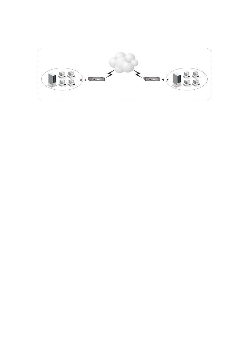
The Barricade can be configured as a bridge for making a transparent
connection to a remote site, or as a router for accessing the Internet. These
applications are briefly described in the following sections.
Accessing a Remote Site
The Barricade can be configured to act as a transparent bridge between a
local PC or LAN attached to the Ethernet port and a remote site across
the ADSL link. Bridging can be used to make two separate networks
appear as if they were part of the same physical network. When data enters
the Ethernet port, its destination MAC address (physical address) is
checked in the address database to see if it is located in the local segment
(i.e., attached to the Barricade’s Ethernet port). If the destination address is
not found, the frame is forwarded to the ADSL port and queued for
output. If the destination address is found to belong to the local port, the
frame is dropped or “filtered.” However, broadcast or multicast frames are
always broadcast across the ADSL link.
The source MAC address of each frame is recorded into the address
database only if it belongs to the local LAN segment. This information is
then used to make subsequent decisions on frame forwarding. The address
database can hold up to 128 unique MAC addresses. An entry in the
address database will be discarded only if it has not been accessed for a
period of time called the aging time. This is to ensure that correct
forwarding decisions can still be made when a node is moved to another
port, and to keep the table clean. The aging time has a default value of 10
minutes.
Note: Compared to routing, bridging generates more traffic for each network
protocol, and uses more CPU time and system memory. Therefore, you
should only bridge if you need to use protocols other than TCP/IP.
1-7
Page 22
I
NTRODUCTION
ADSL
RouterRouter
10/100 Mbps Ethernet LAN
10/100 Mbps Ethernet LAN
Figure 1-1. Transparent Bridged Network
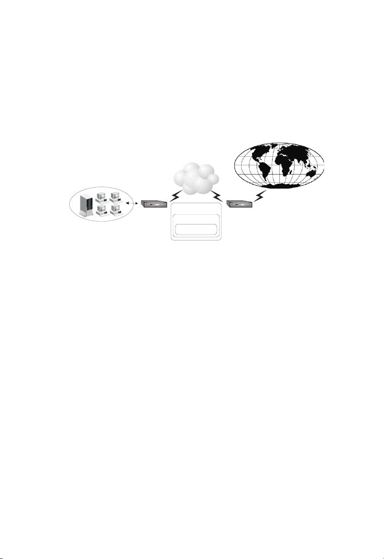
Accessing the Internet
To access the Internet, which uses TCP/IP protocols exclusively, the
Barricade must be configured to function as a router. One interface is the
port attached to a local Ethernet LAN (or directly to a host PC with an
Ethernet adapter), while the other is the ATM transport service running
on the DSL port. When the router receives an IP packet, the destination
network address is checked in the routing table. If the address is found, the
packet is forwarded to the associated interface/port. Otherwise, the packet
is dropped.
The routing table contains information on which networks are accessible
through each interface. The information can be dynamically updated using
the routing information protocol (RIP), or statically configured through
the management interface. If you use RIP, the router will exchange
information with neighboring routers to learn the best routes to remote
networks, and advertise the networks for which it can provide the best
route.
1-8
Page 23
N
ETWORK APPLICATIONS
When the system is powered on, the Barricade builds its own routing
database according to previous static routing entries, and/or collects
routing information from adjacent routers through RIP 2 protocol. RIP-1
is generally supported by all routers, but RIP 2 carries more information
which allows the Barricade to make better choices on the most appropriate
path to a remote network.
ADSL
Internet
Router
Local Area Network
ADSL
PPP/ATM
TCP/IP Protocol
ISP
DSLAM
Figure 1-2. Routed Network
1-9
Page 24

I
NTRODUCTION
1-10
Page 25

C
HAPTER
I
NSTALLATION
Before installing the Barricade, verify that you have all the items listed
under “Package Contents.” If any of the items are missing or damaged,
contact your local distributor. Also be sure that you have all the necessary
cabling before beginning the installation. After installing the Barricade,
refer to the Web-based configuration program (see Chapter 3) to learn
how to configure the router.
Package Contents
After unpacking the Barricade, check the contents of the box to be sure
that you have received the following components:
• Barricade (SMC7401BRA)
• External power adapter
• RJ-11 cable
2
• RJ-45 crossover cable
• CD-ROM containing drivers and manual in PDF format
•This User Guide
• Warranty card
Immediately inform your dealer in the event of any incorrect, missing, or
damaged parts. If possible, please retain the carton and original packing
materials in case there is a need to return the Barricade.
2-1
Page 26

I
NSTALLATION
Hardware Description
The Barricade provides a high-speed Asynchronous Digital Subscriber
Line (ADSL) that connects to a remote site (via bridging) or to the
Internet (via routing). It transports data over standard telephone wire at
full-rate ADSL (G.dmt: 8 Mbps downstream, 640 Kbps upstream) or
splitterless ADSL (G.lite: 1.5 Mbps downstream, 512 Kbps upstream)
connection speeds.
LED Indicators
The unit includes an LED display on the front panel for system power and
port indications that simplifies installation and network troubleshooting.
LED Operation Description
PWR On: Normal operation
Off: Power off or device failure
Sync On: ADSL loop is up
Off: ADSL loop is down or
Barricade flash memory is
corrupt
Slow blink: The Barricade is training
Data blink: The Barricade is
sending/receiving data across
the WAN
2-2
Page 27

H
ARDWARE DESCRIPTION
LED Operation Description
USB Activity On: The Barricade is in USB
Ethernet
Activity
configured state and driver is
loaded
Off: The Barricade is NOT in USB
configured state or driver is not
loaded
Slow blink: The Barricade flash
memory is corrupt or flash
memory is being updated.
On: The Barricade is connected to
an Ethernet port
Off: The Barricade is not connected
to an Ethernet port
Slow blink: 1 second ON, 1 second OFF
Data blink: Cycle dependent on data being sent/received
Rear Panel
The rear panel provides the following ports:
• One USB port for connection to a PC
• One RJ-45 port for connection to a 10BASE-T/100BASE-TX
Ethernet Local Area Network (LAN). This port operates at
10/100 Mbps, half/full duplex, and is wired as MDI (i.e., no internal
crossover).
• One RJ-11 port for connection to your ADSL service provider’s
incoming line, using a voice/data splitter for full-rate ADSL (G.dmt)
or a direct connection for splitterless ADSL (G.lite).
Figure 2-1. Rear Panel
2-3
Page 28

I
NSTALLATION
System Requirements
You must have access to an ADSL network that meets the following
minimum requirements:
• ADSL service from your local telephone company or Internet Service
Provider (ISP), or access to an ADSL Digital Subscriber Line Access
Module (DSLAM) at your local site.
• PC configured with a fixed IP address or using dynamic IP address
assignment via DHCP, as well as a Gateway server address and DNS
server address from your service provider or network administrator.
• You need to get Virtual Channel Identifiers (VCI) and Virtual Path
Identifiers (VPI) from your service provider or network administrator
to set up a Permanent Virtual Connection (PVC) for your ATM data
flow.
2-4
Page 29
C
ONNECT THE SYSTEM
Connect the System
Phone Line Configuration
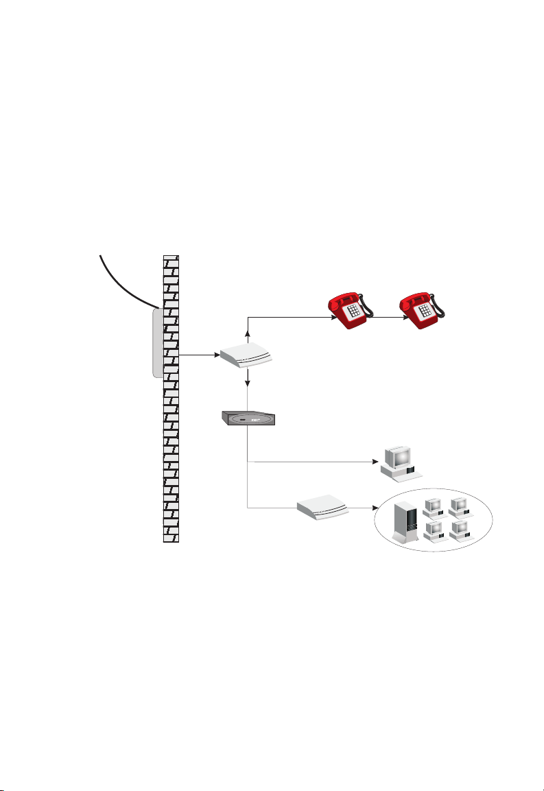
Installing a Full-rate Connection
If you are using a full-rate (G.dmt) connection, your service provider will
attach the outside ADSL line to a data/voice splitter. In this case you can
connect your phones and computer directly to the splitter as shown below:
Plain Old
Telephone
System (POTS)
Residential
Connection
Point (NID)
Voice
Data
Splitter
ADSL Router
or
Ethernet
hub or switch
Figure 2-2. Installing the Barricade with a Splitter
2-5
Page 30
I
NSTALLATION
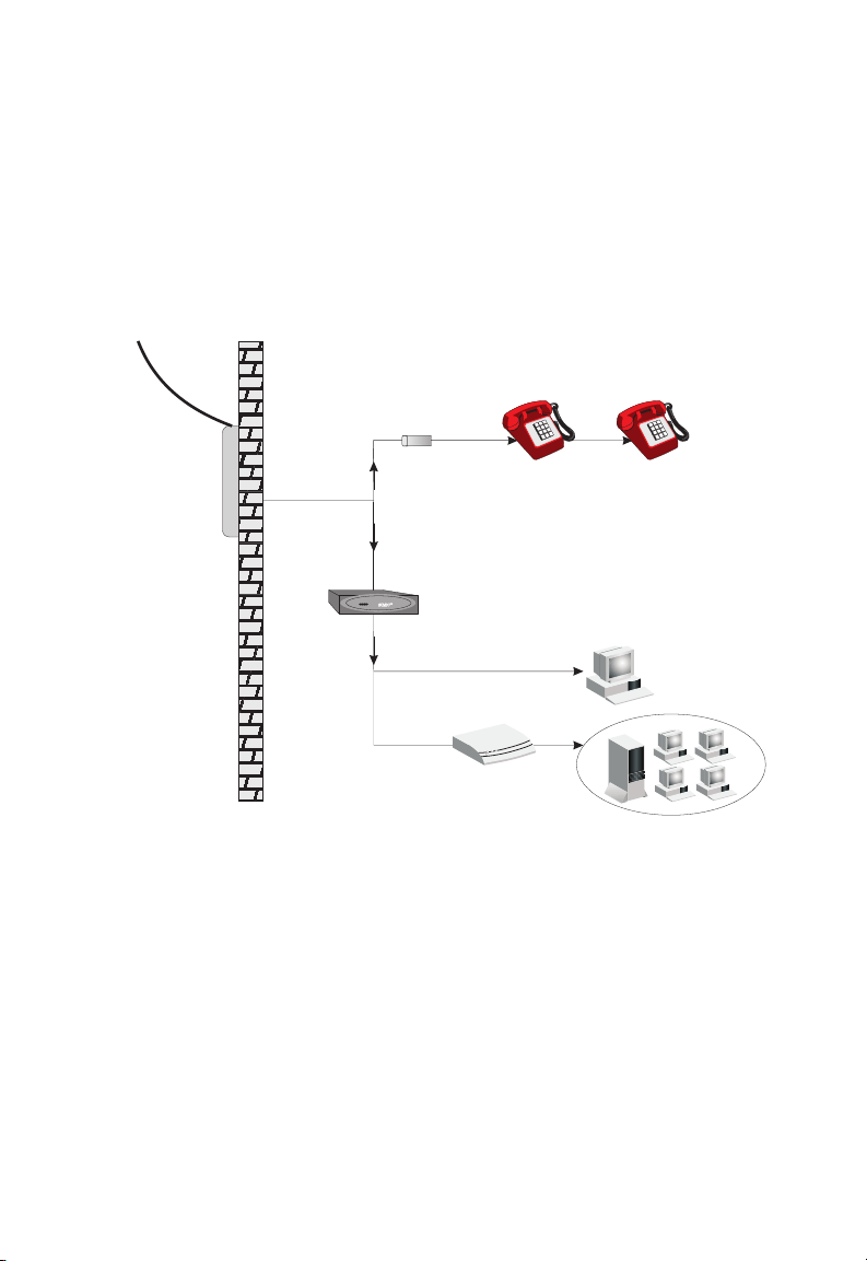
Installing a Splitterless Connection
If you are using a splitterless (G.lite) connection, then your service
provider will attach the outside ADSL line directly to your phone system.
In this case you can connect your phones and computer directly to the
incoming ADSL line, but you will have to add low-pass filters to your
phones as shown below:
Plain Old
Telephone
System (POTS)
Voice
Residential
Connection
Point (NID)
Voice
& Data
Voice
& Data
Data
Filter
ADSL Router
or
Ethernet
hub or switch
Figure 2-3. Installing the Barricade without a Splitter
2-6
Page 31

C
ONNECT THE SYSTEM
Connect the ADSL Line
Run standard telephone cable from the wall jack providing ADSL service
to the ADSL port on your Barricade. When inserting an RJ-11 plug, be
sure the tab on the plug clicks into position to ensure that it is properly
seated. If you are using splitterless ADSL service, be sure you add low-pass
filters between the ADSL wall jack and your telephones. (These filters pass
voice signals through but filter data signals out.)
Connect the Power Adapter
Plug the power adapter into the power socket on the rear of the Barricade,
and the other end into a power outlet.
Check the PWR (power) indicator on the front panel is lit. If the power
i
ndicator is not lit, refer to Appendix A Troubleshooting
In case of a power input failure, the Barricade will automatically restart and
begin to operate once the input power is restored.
If the Barricade is properly configured, it will take about 30 seconds to
establish a connection with the ADSL service provider after powering up.
During this time the Sync indicator will flash. After the ADSL connection
has been established, the ADSL Sync LED will stay on.
.
Connect to the Barricade’s Ethernet Port
Connect directly to a PC or server equipped with an Ethernet network
interface card using the crossover cable supplied with the Barricade.
However, when connecting the Barricade to a network device such as an
Ethernet hub or switch, use the crossover cable supplied with the
Barricade to connect to an MDI port on the other device, or use your own
straight-through cable to connect to an MDI-X (i.e., with internal
crossover) port on the other device. Refer to Appendix B for detailed
information on these wiring types. If you connect the Barricade to a
network device, then you need to connect your PCs to that device. When
inserting an RJ-45 plug, be sure the tab on the plug clicks into position to
ensure that it is properly seated.
2-7
Page 32

I
NSTALLATION
Notes: 1. Use 100-ohm straight-through shielded or unshielded
twisted-pair cable with RJ-45 connectors at both ends for all
connections. Use Category 3, 4, or 5 for 10 Mbps connections,
or Category 5 for 100 Mbps connections.
2. Make sure each twisted-pair cable does not exceed 100 meters
(328 feet).
Warning: Do not plug a phone jack connector into any RJ-45 port. This
may damage the Barricade. Use only twisted-pair cables with
RJ-45 connectors that conform with FCC standards.
Connect to the Barricade’s USB Port
1. Insert the square (B-type) USB plug of the USB cable into the USB
port at the back of the modem and the rectangular (A-type) USB plug
into the USB port at the back of the computer.
2. The “Found New Hardware” screen will appear. Insert the driver disk.
When prompted for the location of the driver, enter the drive letter of
your CD drive.
3. Follow the instructions given to install the driver.
4. Reboot your computer if prompted. The modem may take from 1~5
minutes to initialize and establish a connection.
5. Start your browser or other Internet application.
2-8
Page 33

C
HAPTER
W
EB
-B
ASED
Web-Based Configuration and Monitoring
The ADSL Barricade provides an embedded HTTP Web agent. This agent
can be accessed by any computer on the network using a Java-supported
Web browser (including Internet Explorer 4.0 or above, and Netscape
Navigator 4.0 or above). Using the Web browser management interface
you can configure the Barricade or view statistics to monitor network
activity.
Note: You must have TCP/IP configured on your client computers in
order to access the Barricade from a Web browser. See
“Configuring Client TCP/IP” on page 4-1)
Logging into the System
To access the management interface, enter the Barricade’s IP address in
your Web browser (default: 192.168.1.1). Then enter the administrator user
name (default: “admin”) and password (default: “barricade”).
M
ANAGEMENT
3
3-1
Page 34

WEB-B
ASED MANAGEMENT
Navigating the Web Browser Interface
The Barricade’s management interface provides access to the three main
menus – Status, Configuration Setting, and Admin Privilege. The fast
Setup Wizard is also accessible from the home page.
• The Setup Wizard quickly leads you through setting up an ADSL
connection.
• The Configuration Setting menu provides options for the WAN and
LAN connections, NAT, Virtual Server, Bridge Filtering, and DNS
configuration.
• The Admin Privilege menu provides detailed connection status for
WAN, PPP, and TCP. It also
options for other advanced
and upgrading firmware.
• The Status menu provides general information on the firmware
versions, ADSL connection status, as well as LAN settings for the
Barricade and DHCP clients.
includes a broad range of configuration
functions, restoring factory default settings,
3-2
Page 35

N
AVIGATING THE WEB BROWSER INTERFACE
Making Configuration Changes
Configurable parameters have a dialog box or a drop-down list. Once a
configuration change has been made on a page, be sure to click on the
appropriate button on the page to confirm the new setting.
Note: To ensure proper screen refresh after a command entry, configure
Internet Explorer 5.0 as follows: Click “Tools / Internet Options
/ General. In the Temporary Internet Files section, click
“Settings.” The setting for “Check for newer versions of stored
pages” should be “Every visit to the page.”
Setup Wizard
The Setup Wizard quickly leads you through setting up an ADSL
connection.
1. Set the operating mode. Router mode for a regular Internet Service
Provide connection; Bridge mode if you wish to use the Barricade to
connect two separate networks. Click “Next”.
2. Enter the IP address and subnet mask that the Barricade will use on
the local LAN (default is 192.168.1.1 and 255.255.255.0). Click
“Next”.
3. Enter only parameters provided by your ISP to set the WAN link.
Click “Next”.
4. Enter the default gateway, enable/disable NAT/NAPT (Network
Address Translation/Network Address and Port Translation as
required, set the DNS server discovery method, and enter a preferred
and alternate DNS server if required. Click “Next”.
5. Click ‘Reboot” to write the settings into the Barricade flash memory.
3-3
Page 36

WEB-B
ASED MANAGEMENT
Menu Overview
The Web management interface allows you to define system parameters,
manage and control the Barricade and its ports, and monitor network
conditions. The following table briefly describes the selections available
from this program.
Menu Description
Configuration Setting
WAN ADSL link settings, including Default Gateway, IP address,
ATM PVC settings including UBR (Unspecified Bit Rate)
and CBR (Constant Bit Rate), encapsulation method,
bridging for multiple protocols, IGMP multicast support,
PPP, and enabling the Barricade as a DHCP client.
LAN Configuration of the local IP address, enabling the Barricade
as a DHCP server, defining a DHCP address pool, and
setting the Ethernet port to a fixed speed/duplex mode or
for auto-negotiation.
NAT Configures static address mapping for specific hosts (NAT),
or multi-user local address translation to a single external
address (NAPT).
Virtual Server Redirects remote users accessing services (e.g., Web or FTP)
at your local site via a public IP address to local servers
configured with private IP addresses/ports.
Bridge Filtering Packet filtering based on source or destination MAC
DNS Sets DNS discovery options, or adds preferred and alternate
Reboot Writes the current configuration settings to flash memory
addresses, or Ethernet frame type.
DNSs (Domain Name Servers).
and reboots the system.
3-4
Page 37

M
ENU OVERVIEW
Menu Description
Admin Privilege
WAN Status Displays the IP address, subnet mask, and MAC address
PPP Status Displays the status of PPP links for each VC.
TCP Status Displays the status of overall TCP traffic.
Route Table Configures static routes.
Learned MAC Addr. By examining the MAC source address of each received
ADSL
Configuration
RIP Configuration Configures RIP unicast routing for TPC/IP access to the
Password
Configuration
Misc Configuration Enables WAN-side HTTP/FTP/TFTP servers, DMZ
Reset to Factory
Default
Diagnostic Test Runs a diagnostic test on the LAN connection, and for each
Code Image Update Downloads new firmware to the Barricade, using a file
Network Code
Image Update
System Log All key configuration changes or detected errors are
Reboot Writes the current configuration settings to flash memory
associated with each ATM Virtual Circuit (VC). Provides
release/renew IP address option.
frame, and recording the port on which it was received, the
Barricade learns the location of specific nodes and only
forwards frames which need to travel from one LAN to
another.
Configures basic ADSL connection parameters, including
Trellis encoding, handshaking protocol, and wiring option.
Internet.
Sets a password for read/write access for the administrator,
or for read-only access for a guest.
access for a specified client, DNS proxy, DHCP relay,
IGMP Proxy, and SNMP community strings
Restores the original factory settings.
PVC used in the ADSL connection.
selected from the network.
Downloads new firmware to the Barricade directly from
your distributor’s support site.
recorded in this log.
and reboots the system.
3-5
Page 38

WEB-B
ASED MANAGEMENT
Parameter Description
Status
Software Version System firmware version in ROM.
Customer Software
Version
IP Address The public IP address of the Barricade.
Subnet Mask The Subnet Mask of the Barricade.
MAC Address The MAC Address of the Barricade.
IP Address The internal IP address of the Barricade.
Subnet Mask The internal Subnet Mask of the Barricade.
MAC Address The MAC Address of the Barricade.
Number of Ethernet
devices connected to the
DHCP server
Interface customization version.
Number of internal devices currently connected to the
DHCP server.
Configuration Settings
Use the Configuration menus to
access the basic options for WAN and
LAN connections, NAT, Virtual Server, Bridge Filtering, and DNS
configuration.
WAN
Note:
This screen is used to configure the ADSL link, including IP
ATM PVC, encapsulation method, bridging for multiple
address,
protocols, IGMP multicast support, PPP, and enabling DHCP
client service.
3-6
Page 39

C
ONFIGURATION SETTINGS
Note: Only use values provided by your ISP to configure the WAN link.
3-7
Page 40

WEB-B
ASED MANAGEMENT
Parameter Default Description
System Wide Settings
Default Gateway 0.0.0.0 This address is configured by the network
Per VC Settings
Enabled? Yes Enables or disables WAN connection.
VPI 8 Virtual Path Indicator. Each connection
VCI 32 Virtual Channel Indicator. Each connection
1
Static IP Address
Subnet Mask
Service Category UBR Bit rate supported by your ISP:
Bandwidth Bandwidth supported by your ISP.
Encapsulation
Bridge Enabled Sets the Barricade to function as a bridge to
IGMP Disabled Enables or disables the multicast host
PPP Point-to-point transport protocol
Service Name Service name provided by ISP.
Username User name provided by ISP.
Password Password provided by ISP.
Disconnect Timeout0 Time after which an inactive link is
Authentication Auto Sets the authentication mode used to login
192.168.241.101 IP address of the ADSL port.
1
255.255.255.0 Subnet mask of the ADSL port.
2,3
1483 Bridged IP
LLC
administrator and it informs each computer
or other network device where to send data
if the target station does not reside on the
same subnet as the source.
must have a unique pair of <VPI, VCI>
settings.
must have a unique pair of <VPI, VCI>
settings.
UBR: Undefined Bit Rate
CBR: Constant Bit Rate
Specifies how to handle multiple protocols
at the ATM transport layer.
connect two separate networks.
registration protocol.
terminated.
to your ISP.
3-8
Page 41

C
ONFIGURATION SETTINGS
Parameter Default Description
Automatic
Reconnect
DHCP Dynamic Host Configuration Protocol.
DHCP client enable Configures the barricade’s IP address via
Host Name Your ISP may require you to enter a host
Virtual Circuit The virtual connection that the WAN
1. The static address is not used if “DHCP client enable” is selected.
2. See “Protocol Encapsulation” below.
3. See “Protocol Multiplexing” on page 3-11.
Automatically reestablishes connection as
required for any client application.
DHCP.
name here.
settings on this page configure.
Asynchronous Transfer Mode (ATM)
ADSL provides a reliable connection to your service provider. Traffic is
carried over the ADSL physical link layer using ATM protocol. This
protocol allows you to designate multiple paths between locations (Virtual
Path), and multiple data channels within each path (Virtual Channel).
ATM Permanent Virtual Circuits (PVCs) are provided.
Just set the VPI
(Virtual Path Indicator) and VCI (Virtual Channel Indicator) for each PVC
to the values provided by your ISP. For home use, usually only one
connection will be configured.
Eight
Protocol Encapsulation
Traffic passing over the ADSL connection must be encapsulated into a
recognized ATM protocol. (Data is segmented into short fixed length cells
when entering the ATM stream, and reassembled into variable length user
information when leaving the stream). The Barricade router supports the
following protocols:
• PPPoA VC-Mux. Point to Point Protocol over ATM Virtual Circuit
Multiplexer (null encapsulation) allows only one protocol running per
virtual circuit (less overhead).
3-9
Page 42

WEB-B
ASED MANAGEMENT
• PPPoA LLC. Point to Point Protocol over ATM Logical Link Control
allows multiple protocols running over one virtual circuit (slightly
more overhead).
• 1483 Bridged IP LLC (Logical Link Control) provides indirect access
to the Internet by flooding, forwarding or filtering bridged protocols
through each relevant virtual circuit.
Bridging is a standardized layer 2 technology. It is typically used in
corporate networks to extend the physical reach of a single LAN
segment and increase the number of stations on the common LAN
without compromising performance. Bridged data is encapsulated
using the RFC1483 protocol to enable data transport.
• 1483 Routed IP LLC (Logical Link Control). The barricade looks up
the network address for each packet seen on the LAN port. If the
address is listed in the routing table as local, it is filtered. If the address
is listed under the ADSL port, it is forwarded. Or if the address is not
found, then it is automatically forwarded to the default router (i.e., the
ADSL router at the head end).
Routing is often contrasted with bridging. The primary difference
between the two is that bridging occurs at Layer 2 (the link layer) of the
OSI reference model, whereas routing occurs at Layer 3 (the network
layer).
• 1483 Bridged IP VC-Mux. Bridged IP Virtual Circuit Multiplexer (null
encapsulation) allows only one protocol running per virtual circuit with
less overhead.
• 1483 Routed IP VC-Mux. Routed IP Virtual Circuit Multiplexer (null
encapsulation) allows only one protocol running per virtual circuit with
less overhead.
• Classical IP over ATM provides a direct replacement for IP links
between routers, using IP to ATM address mapping.
• Native ATM. Asynchronous Transfer Mode. International standard
for cell relay in which multiple service types (such as voice, video, or
data) are conveyed in fixed-length (53-byte) cells. Fixed-length cells
allow cell processing to occur in hardware, thereby reducing transit
delays. ATM is designed to take advantage of high-speed transmission
media.
3-10
Page 43

C
ONFIGURATION SETTINGS
• PPPoE VC-Mux. Point to Point Protocol over Ethernet Virtual Circuit
Multiplexer uses PPP to bridge multiprotocol traffic over Ethernet to
the ISP’s router. Each PPP connection first learns the Ethernet address
of its remote peer, and then establishes a unique session identifier.
• PPPoE LLC. Point to Point Protocol over Ethernet Logical Link
Control allows multiple protocols running over one virtual circuit with
a little bit more overhead
• PPPoE None.
Your service provider will tell you which connection type to use.
Protocol Multiplexing
Protocol multiplexing allows you access a remote site using protocols such
as IP, Novell IPX, or Windows NetBuei networks just as though you were
attached to the local LAN. Also, note that all broadcast and multicast
frames entering the LAN port are always forwarded to the ADSL port.
Some of the encapsulation methods provided by this router support two
methods for carrying traffic over an ATM connection. LLC (Logical Link
Control) Encapsulation allows multiplexing of multiple protocols over a
single virtual circuit, where each data packet contains an extra field
identifying the protocol. While VC Based Multiplexing carries each
protocol over a separate virtual circuit and therefore does not need to
include any explicit information identifying the protocol type.
Since VC multiplexing does not include the additional protocol identifiers
used in LLC encapsulation, you should use this method whenever possible
to maximize bandwidth utilization. If your ISP only supports one Virtual
Circuit, use VC multiplexing unless more than one protocol is carried over
the link. You should also use VC multiplexing with encapsulation methods
such as IP/ATM which only requires one transport protocol.
3-11
Page 44

WEB-B
ASED MANAGEMENT
LAN
This screen is used to configure
local IP address, enabling DHCP service, and setting the port to a fixed
speed/duplex mode or for auto-negotiation.
parameters for the Ethernet port, including
Parameter Default Description
LAN Configuration
IP Address 192.168.1.1 IP address of the LAN port.
Subnet Mask 255.255.255.0 Subnet mask of the LAN port.
DHCP Server Dynamic Host Configuration Protocol
DHCP address pool
selection.
User Defined Start
Address
192.168.1.2 First address assigned to clients.
System Allocated: IP address pool allocated
by the Barricade
User Defined: The user defines the IP
address pool.
3-12
Page 45

C
ONFIGURATION SETTINGS
Parameter Default Description
User Defined End
Address
Lease Time 0 The amount of time an IP address is leased
Ethernet Mode
Setting
192.168.1.13 Last address assigned to clients.
Range: Up to 253 addresses
to the requesting client. (The address may
be released back to the Barricade by the
host if it shuts down before the lease time
expires.)
AutoSense Sets the LAN port to a fixed speed and
duplex mode, or enables auto-negotiation
for these settings.
Dynamic Host Configuration Protocol (DHCP) allows hosts on a TCP/IP
network to dynamically obtain basic configuration information, including
an IP address, network gateway address, and domain name server (DNS)
address.
DHCP can be used by the Barricade for dynamic IP address assignment as
a server (by selecting DHCP under LAN Configuration) or as a server
relay (see “Misc Configuration” on page 3-28). When a DHCP client starts,
it broadcasts a DHCP request looking for DHCP servers. The Barricade
can be configured to respond to this packet or to relay the request on to
another DHCP server located anywhere on the other side of the ADSL
connection. If the Barricade is configured to respond to a DHCP client
request, it will return an IP address, subnet mask, gateway address, and
DNS address.
3-13
Page 46

WEB-B
ASED MANAGEMENT
NAT Configuration
NAT (Network Address Translation) and NAPT (Network Address and
Port Translation) convert IP addresses on a private network (designated as
“internal” or “Local Area Network” (LAN) to global IP addresses that can
forward packets to another registered network (designated as “external” or
“Wide Area Network” (WAN), with all traffic passing through the firewall.
NAT/NAPT re-writes the IP headers of internal packets going out,
making it appear that they all came from the firewall, and enables multiple
PCs on the LAN to access the Internet for the cost of one Internet
account and one IP address. Reply packets coming back are re-translated
and forwarded to the appropriate internal machine/port. Thus, internal
machines are allowed to connect to the outside world. However, external
machines cannot find the internal machines since they are aware of only
one IP address, that of the firewall. By protecting the single network
firewall, the entire internal network can be protected.
NAPT is a special case of NAT, where many IP numbers are hidden
behind a number of addresses. In contrast to the original NAT, the number
of connections is not limited to that number. With NAPT, an almost
arbitrary number of connections is multiplexed using TCP port
information.
NAT and NAPT can also secure your network from direct attack by
hackers and provide more flexible management by allowing you to change
3-14
Page 47

C
ONFIGURATION SETTINGS
internal IP addresses without affecting outside access to your network.
Parameter Default Description
NAT NAPT IP address mapping between the LAN and
WAN.
Session Name A name used to identify the static
for a specified local IP address.
User’s IP The static address for a local user.
mapping
3-15
Page 48

WEB-B
ASED MANAGEMENT
NAT Session Name Configuration
This screen is used to assign a NAT session to a virtual circuit.
Parameter Default Description
Session Name A name used to identify the static
for a specified local IP address.
Virtual Circuit 0 The permanent virtual circuit to which this
NAT session is assigned.
mapping
3-16
Page 49

C
ONFIGURATION SETTINGS
Virtual Server
This screen is used to redirect remote users requesting services (e.g., Web,
FTP) on your local network from the Barricade’s public IP address to
internal host servers configured with private IP addresses. Depending on
the requested service (TCP/UDP port number), the Barricade redirects
the external service request to the appropriate server (located at another
internal IP address). This secures your network from direct attack by
hackers, and provides more flexible management by allowing you to
change internal IP addresses without affecting outside access to your
network.
Parameter Description
ID Identifies this virtual server configuration
Public Port Port number for the supported service provided to
remote users (e.g., 80: HTTP, 21: FTP).
Private Port Port number of designated service on local server.
Port Type TCP or UDP services may be specified.
Host IP Address IP address of a local server.
3-17
Page 50

WEB-B
ASED MANAGEMENT
Bridge Filtering
Traffic from a node that presents a security risk or is functioning
improperly can be filtered from the Barricade. This screen is used to filter
or forward traffic matching the specified source MAC address, destination
MAC address, or Ethernet frame type.
Parameter Description
Enable Bridge Filtering Enables/disables filtering for the specified items.
Source MAC Any frame with this source MAC address.
Destination MAC Any frame with this destination MAC address.
TYPE Any frame matching the specified Ethernet type.
Block/Forward Will block or forward frames matching this criteria.
Note: If you specify any item to be forwarded, then all other frames that
do not match this criteria will be discarded.
3-18
Page 51

C
ONFIGURATION SETTINGS
DNS
This screen is used to specify the default gateway and domain name
servers.
Parameter Description
DNS Proxy Selection Selects a DNS server by auto-discovery, user configured,
or a combination of both methods.
Preferred DNS Server* Enter a user configured preferred DNS Server.
Alternate DNS Server* Enter a user configured alternate DNS Server.
* Your ISP may provide values for these fields.
Reboot
After making any changes, reboot the Barricade to make the changes
effective.
3-19
Page 52

WEB-B
ASED MANAGEMENT
Admin Privilege
Use the Admin Privilege menus to
PPP, and TCP status, or to configure the static routing table, ADSL
connection options, RIP parameters, management passwords, and other
advanced features.
display detailed information on WAN,
WAN Status
This screen shows the IP address, subnet mask, and MAC address
associated with each permanent virtual circuit.
To acquire a new IP address from the DHCP server:
1. Choose the virtual circuit number from the Virtual Circuit dropdown
list.
2. Choose “Release” and click “Execute”.
3. Choose “Renew” and click “Execute”.
3-20
Page 53

PPP Status
This screen displays the status of PPP connections configured for
permanent virtual circuit. Use this screen to disconnect
link operating on a specified virtual circuit.
A
DMIN PRIVILEGE
any
or reconnect a PPP
3-21
Page 54

WEB-B
ASED MANAGEMENT
TCP Status
This screen displays statistics for all TCP traffic crossing the Barricade, as
well as general statistics on the number of individual TCP connections.
This information can be used to identify potential problems with the
Barricade (such as a faulty port or synchronization problems between the
Barricade and head end).
3-22
Page 55

A
DMIN PRIVILEGE
Route Table
This screen is used to manually configure static routes to other IP
networks, subnetworks, or hosts.
Parameter Description
Destination A destination network or specific host to which packets
Gateway The IP address of the router at the next hop to which
Netmask The subnetwork associated with the destination.
Interface The local interface through which the next hop of this
Action Add or delete a route from the table.
can be routed.
matching frames are forwarded.
This is a template that identifies the address bits in the
destination address used for routing to specific subnets.
Each bit that corresponds to a “1” is part of the network/
subnet number; each bit that corresponds to “0” is part of
the host number.
route is reached. Values include:
cs0: Interface of ethernet port.
ppp0: Interface of PVC when the PVC is set to PPP/
ATM mode.
lo0: Interface of the loopback driver.
3-23
Page 56

WEB-B
ASED MANAGEMENT
Learned MAC Addr.
The MAC (Media Access Control) address is Ethernet hardware’s unique
identification number. When you're connected to the Internet from your
computer (or host as the Internet protocol thinks of it), a correspondence
table relates your IP address to your computer's physical (MAC) address on
the LAN.
3-24
Page 57

A
DMIN PRIVILEGE
ADSL Configuration
This screen is used to configure ADSL connection options for encoding,
handshaking, and wiring type.
Parameter Default Description
Trellis Enabled An encoding method that limits the impact
of line noise on transmitted signals.
Handshake Protocol G.dmt ADSL protocol to use on the WAN link:
Autosense - G.dmt first
Autosense - T1.413 first
G.dmt/G.lite
T1.413 (CAP)
G.dmt
G.lite
Wiring Selection Tip/Ring The wiring option used for the phone plug
attached to the WAN port.
Options:Auto, Tip/Ring, A/A1
3-25
Page 58

WEB-B
ASED MANAGEMENT
RIP Configuration
This screen is used to configure the dynamic routing protocol used to
learn new IP routes.
Parameter Default Description
RIP Disabled Enables/disables dynamic routing.
Supplier True Set this to True if you want the Barricade to
broadcast routing information as well as
accept routing information.
Gateway False When True (and the Supplier flag is set to
True), RIP advertisements include a default
gateway (0.0.0.0) entry. We recommend
thi s N OT be set to Tr ue , a s this woul d m ak e
the whole world use you as their default
gateway and forward all internet traffic to
you.
3-26
Page 59

A
DMIN PRIVILEGE
Parameter Default Description
Multicast False This field controls the way in which RIP 2
routing messages are sent to other routers.
Multicast can be set to:
True: RIP-2 messages are multicast.
False: RIP-2 messages are broadcast*.
Interval 30 The interval at which the router broadcasts
routing information (in seconds).
* Use this option if the router must share routing information with other devices
on the network that use RIP 1.
3-27
Page 60

WEB-B
ASED MANAGEMENT
Password Configuration
Administrators have Read/Write access to all configuration parameters
and statistics. You should therefore change the default Administrator
password as soon as possible, and store it in a safe place. (If for some
reason your password is lost, or you cannot gain access to the management
interface, contact your distributor for assistance). The fixed administrator
username is “admin” and the default administrator password is
“barricade.” The fixed user’s username is “user” and the default user
password is “password.”
Misc Configuration
This screen includes options to enable local HTTP/FTP/TFTP servers
for remote user access, DMZ access for a specified client, DNS proxy,
3-28
Page 61

A
DMIN PRIVILEGE
DHCP relay, IGMP proxy, and allows you to enter SNMP communuty
strings.
3-29
Page 62

WEB-B
ASED MANAGEMENT
WAN side HTTP
server
FTP server Enabled Enables/disables FTP server access.
TFTP server Disabled Enables/disables TFTP server access.
HTTP server port 80 Sets the port used for HTTP services.
Parameter Default Description
Disabled Enables/disables HTTP server access.
The Path to the file c:\smc7401\ The default path to the downloaded
Filename firmware.dlf The upgrade firmware file.
Upload FTP Server
Username
Upload FTP Server
Password
Upload FTP Server IP 192.168.1.2 Default FTP Server password.
1
DMZ
DMZ Host IP 0.0.0.0 Client authorized DMZ access.
DNS Proxy Disabled Enables/disables forwarding of client
DHCP Relay Disabled Enables/disables forwarding of client
DHCP Target IP
anonymous Default username for the FTP Server.
password Default password for the FTP Server.
Disabled Enables/disables DMZ access.
2
0.0.0.0 Server on the outbound network to which a
upgrade file.
queries for domain name mapping to a
server located on another subnet or on
another network.
configuration queries to a server on another
subnet or on another network.
DHCP broadcast request is relayed. To
relay a request to a network attached to this
router’s ADSL port, specify the appropriate
network address suffixed with “255.” To
broadcast a query for any DHCP server
located on the WAN side, specify a null
address (i.e., the default setting).
3-30
Page 63

A
DMIN PRIVILEGE
Parameter Default Description
IGMP Proxy Disabled Allows local users not directly connected to
a downstream router (i.e., an intermediate
multicast router) to be able to join a
multicast group sourced from an upstream
network.
PPP reconnect on
WAN access
Disabled Allows automatic PPP reconnection when
an application requests WAN access.
SNMP Read
Community
SNMP Write
Community
1. DMZ can be used to assign a public address to a device on the local LAN. This may be required for certain
applications that need unrestricted access to the Internet, or for remote hosts to access a local server.
2. Your ISP may provide values for this field.
public The SNMP Read Community string is like a
password. It is sent along with each SNMP
Get-Request and allows (or denies) access
to a device.
private An attacker that can guess the “write”
community string can set arbitrary MIB
variables to new values.
Other Miscellaneous Functions
The Barricade also includes several basic system functions –
• Reset to Factory Default – Resets the Barricade settings to the factory
defaults.
• Diagnostic Test – Tests connection for LAN and ADSL circuits.
• Code Image Update – Updates firmware file. The file must be a binary
file for this specific product; otherwise the agent will not accept it.
• Network Code Image Update – Downloads firmware directly from
your distributor’s support site.
• System Log – Lists key configuration changes or system errors.
• Reboot – After making any changes, reboot the Barricade to make the
changes effective.
3-31
Page 64

WEB-B
ASED MANAGEMENT
Status
The Status
the connection status for the Barricade’s WAN and LAN ports.
screen
displays
core and customer
firmware versions and shows
.
Parameter Description
Firmware Info.
Software Version System firmware version in ROM.
3-32
Page 65

Parameter Description
Customer Software
Version
WAN
IP Address The public IP address of the Barricade.
Subnet Mask The Subnet Mask of the Barricade.
MAC Address The MAC Address of the Barricade.
LAN
IP Address The internal IP address of the Barricade.
Subnet Mask The internal Subnet Mask of the Barricade.
MAC Address The MAC Address of the Barricade.
Number of Ethernet
devices connected to the
DHCP server
Interface customization version.
Number of internal devices currently connected to the
DHCP server.
S
TATUS
3-33
Page 66

WEB-B
ASED MANAGEMENT
ADSL
This screen shows the signal status on the ADSL line.
3-34
Page 67

S
TATUS
Parameter Description
ADSL Line State Shows ADSL line status – Activation, Training, Channel
Analysis, Showtime, or Down.
ADSL Startup Attempts The number of times the Barricade has started training
the ADSL line for an acceptable signal rate.
Elapsed Time Length of time this connection has been established.
SNR Margin Operating margin above the minimum acceptable signal
to noise ratio.
Line Attenuation The difference in the power level received at the near end
(that is, your location) compared to that transmitted from
the head end.
Errored Seconds Number of seconds during which signal or handshake
Loss of Signal Failure due to loss of signal at the near end.
Loss of Frame Number of frames dropped due to signal or handshaking
CRC Errors Number of Ethernet Cyclic Redundancy Check errors
Data Rate The current data rate in use on this line.
Latency Simultaneous transport of one or more bearer channels,
errors occurred. These errors occur primarily during
initial modem training.
errors.
detected by this device.
in which all user data is allocated to either the FAST or the
INTERLEAVED path.
3-35
Page 68

WEB-B
ASED MANAGEMENT
LAN
This screen shows LAN settings for the Barricade and DHCP clients.
Parameter Description
IP Address The IP address of the local Ethernet port. Valid IP
addresses consist of four numbers, 1-254, separated by
periods.
Subnet Mask A template that identifies the address bits in the host
address used for routing to specific subnets. Each bit that
corresponds to a “1” is part of the network/subnet
number; each bit that corresponds to “0” is part of the
host number.
MAC Address The MAC address of the Barricade’s Ethernet port.
Number of Ethernet
devices connected to the
DHCP server*
Ethernet Link Status Indicates an Ethernet link to the Barricade.
USB Link Status Indicates a USB link to the Barricade.(USB not available in
*The IP address and corresponding MAC address are displayed for all clients.
The number of client PCs on the LAN that have used the
Barricade’s DHCP server for dynamic IP address
configuration.
this model).
3-36
Page 69

C
HAPTER
C
ONFIGURING
C
LIENT
TCP/IP
Windows 95/98/Me
You may find that the instructions in this chapter do not exactly match
your version of Windows. This is because these steps and screenshots were
created from Windows 98. Windows 95 and Windows Millennium Edition
are similar, but not identical, to Windows 98.
Step 1. Configure TCP/IP Settings
After completing hardware setup by connecting all your network devices,
you need to configure your computer to connect to the Barricade. First
determine how your ISP issues your IP address. Many ISPs issue these
numbers automatically using Dynamic Host Configuration Protocol
(DHCP). Other ISPs provide a static IP address and associated numbers,
which you must enter manually. How your ISP assigns your IP address
determines how you need to configure your computer.
4
Follow these instructions:
1. From the Windows desktop, click the
“Start” button. Choose “Settings,” and
then click “Control Panel.”
4-1
Page 70

C
ONFIGURING CLIENT
2. From “Control Panel”
double-click the “Network”
icon.
3. In the “Network” window,
under the “Configuration”
tab, double-click the “TCP/
IP” item listed for your
network card.
4. Select the “IP Address” tab.
5. If “Obtain an IP address
automatically” is already
selected, your computer is
already configured for
DHCP. Click “Cancel” to
close each window, and skip
to “Step 2. Disable HTTP
Proxy” on page 4-4.” If not,
locate your IP address and
Subnet Mask. Record the
numbers.
TCP/IP
4-2
Page 71

W
INDOWS
95/98/M
E
6. Click the “Gateway” tab and
record the numbers listed
under “Installed gateways.”
7. Click the “DNS
Configuration” tab. Locate
the DNS servers listed
under “DNS Server Search
Order.” Record any listed
addresses.
8. After writing down your
settings, check to make sure
you have recorded them
correctly. Click the “IP
Address” tab and then click
“Obtain an IP address
automatically.” Click “OK.”
9. Windows may need your
Windows 95/98/Me CD to
copy some files. After it
finishes copying, it will
prompt you to restart your
system. Click “Yes” and
your computer will shut
down and restart.
TCP/IP Configuration Setting
IP Address ____.____.____.____
Subnet Mask ____.____.____.____
Primary DNS Server ____.____.____.____
Secondary DNS Server ____.____.____.____
Default Gateway ____.____.____.____
Host Name ____.____.____.____
4-3
Page 72

C
ONFIGURING CLIENT
TCP/IP
Step 2. Disable HTTP Proxy
You need to verify that the “HTTP Proxy” feature of your Web browser is
disabled. This is so that your browser can view the configuration pages for
your Barricade. The following steps are for Internet Explorer and
Netscape. Determine which browser you use and follow the appropriate
steps.
Internet Explorer
1. Open Internet Explorer and
click the stop button. Click
“Tools,” then “Internet
Options.”
2. In the “Internet Options”
window click the
“Connections” tab. Next,
click the “LAN Settings...”
button.
3. Clear all the checkboxes.
4. Click “OK,” and then click
“OK” again to close the
“Internet Options” window.
4-4
Page 73

W
INDOWS
95/98/M
E
Netscape
1. Open Netscape and click
the stop button. Click
“Edit,” then click
“Preferences...”
2. In the “Preferences”
window, under
“Category”
double-click
“Advanced,” then
click “Proxies.” Select
“Direct connection
to the Internet.” Click
“OK.”
3. Repeat these steps for
each Windows 95/
98/Me computer
connected to your Barricade.
Step 3. Obtain IP Settings from Your ADSL Router
Now that you have configured your computer to
connect to your Barricade, it needs to obtain new
network settings. By releasing old DHCP IP settings
and renewing them with settings from your Barricade,
you can also verify that you have configured your
computer correctly.
1. Click “Start,” then “Run...”
4-5
Page 74

C
ONFIGURING CLIENT
2. Type “WINIPCFG” and click
“OK.” It may take a minute or two
for the “IP Configuration”
window to appear.
3. From the drop-down menu, select
your network card. Click “Release”
and then “Renew.” Verify that your
IP address is now 192.168.1.xxx,
your Subnet Mask is
255.255.255.0 and your Default
Gateway is 192.168.1.1. These
values confirm that your Barricade
is functioning. Click “OK” to close the “IP Configuration” window.
TCP/IP
Windows 2000
Step 1. Configure TCP/IP Settings
After completing hardware setup by connecting all your network devices,
you need to configure your computer to connect to the Barricade. First
determine how your ISP issues your IP address. Many ISPs issue these
numbers automatically using Dynamic Host Configuration Protocol
(DHCP). Other ISPs provide a static IP address and associated numbers,
which you must enter manually. How your ISP assigns your IP address
determines how you need to configure your computer.
4-6
Page 75

Follow these instructions:
1. From the Windows desktop,
click the “Start” button.
Click “Settings,” and then
click “Control Panel.”
2. Double-click the
“Network & Dial-Up
Connections” icon.
3. Double-click the icon that
corresponds to the
connection to your
Barricade.
W
INDOWS
2000
4. Click “Properties.”
4-7
Page 76

C
ONFIGURING CLIENT
5. Double-click “Internet
Protocol (TCP/IP).”
6. All the information you
need to record is on the
“Internet Protocol (TCP/
IP) Properties” dialog box.
Use the spaces below to
record the information.
7. If “Obtain an IP address
automatically” and “Obtain
DNS server address
automatically” are already
selected, your computer is
already configured for
DHCP. Click “Cancel” to
close each window, and skip
to “Step 2. Disable HTTP
Proxy” on page 4-9.”
TCP/IP
8. Select “Obtain an IP
address automatically” and then select “Obtain DNS server address
automatically.” Then click “OK” or “Close” to close each window.
TCP/IP Configuration Setting
IP Address ____.____.____.____
Subnet Mask ____.____.____.____
Primary DNS Server ____.____.____.____
Secondary DNS Server ____.____.____.____
Default Gateway ____.____.____.____
Host Name ____.____.____.____
4-8
Page 77

W
Step 2. Disable HTTP Proxy
You need to verify that the “HTTP Proxy” feature of your Web browser is
disabled. This is so that your browser can view the configuration pages for
your Barricade. Determine which browser you use and refer to “Internet
Explorer” on page 4-4 or “Netscape” on page 4-5.
Step 3. Obtain IP Settings from Your Barricade
Now that you have configured your computer to connect to your
Barricade, it needs to obtain new network settings. By releasing old DHCP
IP settings and renewing them with settings from your Barricade, you can
verify that you have configured your computer correctly.
1. From the Windows
desktop, click the “Start”
button, then “Programs,”
then “Accessories,” and
then “Command
Prompt.”
INDOWS
2000
2. In the “Command Prompt” window, type “IPCONFIG/RELEASE”
and press the <ENTER> key.
3. Type “IPCONFIG /RENEW” and press the <ENTER> key. Verify
4-9
Page 78

C
ONFIGURING CLIENT
that your IP address is now 192.168.1.xxx, your Subnet Mask is
255.255.255.0 and your Default Gateway is 192.168.1.1. These values
confirm that your ADSL Router is functioning.
TCP/IP
4. Type “EXIT” and press <ENTER> to close the “Command Prompt”
window.
Your computer is now configured to connect to your ADSL Router.
Windows NT 4.0
Step 1. Configure TCP/IP Settings
After completing hardware setup by connecting your network devices, you
need to configure your computer to connect to the Barricade. First
determine how your ISP issues your IP address. Many ISPs issue these
numbers automatically using Dynamic Host Configuration Protocol
(DHCP). Other ISPs provide a static IP address and associated numbers,
which you must enter manually. How your ISP assigns your IP address
determines how you need to configure your computer.
4-10
Page 79

Follow these instructions:
1. From the Windows
desktop click “Start,”
then “Settings,” and
click “Control Panel.”
2. Double-click the
“Network” icon.
3. Select the
“Protocols” tab.
4. Double-click
“TCP/IP Protocol.”
5. Select the “IP Address”
tab.
6. In the “Adapter”
drop-down list, be sure
your Ethernet adapter is
selected.
W
INDOWS
NT 4.0
7. If “Obtain
an IP address
automatically” is already
selected, your computer
is already configured for
DHCP. Click “Cancel”
to close each window,
and skip to “Step 2.
Disable HTTP Proxy”
on page 4-13.
8. In the “TCP/IP
Properties” dialog box,
4-11
Page 80

C
ONFIGURING CLIENT
under the IP address tab, locate your IP address, subnet mask, and
default gateway. Record these values in the spaces provided below.
9. Click the “DNS” tab to
see the primary and
secondary DNS servers.
Record these values in
the spaces provided
below.
10. After writing down your
IP settings, click the IP
address tab. Select
“Obtain IP address
automatically” and click
“OK”. Click “OK” again
to close the “Network”
window.
11. Windows may copy some
files, and will then prompt you to restart your system. Click “Yes” and
your computer will shut down and restart.
TCP/IP
4-12
TCP/IP Configuration Setting
IP Address ____.____.____.____
Subnet Mask ____.____.____.____
Primary DNS Server ____.____.____.____
Secondary DNS Server ____.____.____.____
Default Gateway ____.____.____.____
Host Name ____.____.____.____
Page 81

W
INDOWS
Step 2. Disable HTTP Proxy
You need to verify that the “HTTP Proxy” feature of your Web browser is
disabled. This is so that your browser can view the configuration pages for
your Barricade. Determine which browser you use and refer to “Internet
Explorer” on page 4-4 or “Netscape” on page 4-5.
Step 3. Obtain IP Settings from Your Barricade
Now that you have configured your computer to connect to your
Barricade, it needs to obtain new network settings. By releasing old DHCP
IP settings and renewing them with settings from your Barricade, you will
verify that you have configured your computer correctly.
1. From the Windows desktop,
click the “Start” button,
“Programs,” and then select
“Command Prompt.”
2. In the “Command Prompt”
window, type “IPCONFIG
/RELEASE” and press the
<ENTER> key.
NT 4.0
4-13
Page 82

C
ONFIGURING CLIENT
3. Type “IPCONFIG /RENEW” and press the <ENTER> key. Verify
that your IP address is now 192.168.1.xxx, your Subnet Mask is
255.255.255.0 and your Default Gateway is 192.168.1.1. These values
confirm that your Barricade is functioning.
TCP/IP
4. Type “EXIT” and press <ENTER> to close the “Command Prompt”
window.
Your computer is now configured to connect to the Barricade.
Configuring Your Macintosh Computer
You may find that the instructions here do not exactly match your screen.
This is because these steps and screenshots were created using Mac OS
8.5. Mac OS 7.x and above are all similar, but may not be identical to Mac
OS 8.5.
Step 1. Configure TCP/IP Settings
After completing hardware setup by connecting your network devices, you
need to configure your computer to connect to the Barricade. First
determine how your ISP issues your IP address. Many ISPs issue these
numbers automatically using Dynamic Host Configuration Protocol
(DHCP). Other ISPs provide a static IP address and associated numbers,
which you must enter manually. How your ISP assigns your IP address
determines how you need to configure your computer.
4-14
Page 83

C
ONFIGURING YOUR MACINTOSH COMPUTER
.
Follow these instructions:
1. Pull down the Apple Menu.
Click “Control Panels” and
select “TCP/IP.”
2. In the TCP/IP dialog box,
make sure “Ethernet” is
selected in the “Connect
via:” field.
3. If “Using DHCP
Server” is already
selected in the
“Configure” field,
your computer is
already configured
for DHCP. Close the
TCP/IP dialog box,
and skip to “Step 2.
Disable HTTP
Proxy” on page
4-16”
4. All information you need to record is on the “TCP/IP” dialog box.
4-15
Page 84

C
ONFIGURING CLIENT
Use the space below to record the information.
5. After writing down your IP settings, select “Using DHCP Server” in
the “Configure” field and close the window.
TCP/IP
6. Another box will appear
asking whether you want to
save your TCP/IP settings.
Click “Save.”
TCP/IP Configuration Setting
IP Address ____.____.____.____
Subnet Mask ____.____.____.____
Primary DNS Server ____.____.____.____
Secondary DNS Server ____.____.____.____
Default Gateway ____.____.____.____
Host Name ____.____.____.____
Step 2. Disable HTTP Proxy
You need to verify that the “HTTP Proxy” feature of your Web browser is
disabled. This is so that your browser can view the configuration pages for
your Barricade. The following steps are for Internet Explorer and
Netscape. Determine which browser you use and follow the appropriate
steps.
Internet Explorer
1. Open Internet Explorer and click the stop
button. Click “Edit” and select “Preferences.”
2. In the Internet Explorer Preferences window,
under Network, select “Proxies.”
4-16
Page 85

C
ONFIGURING YOUR MACINTOSH COMPUTER
3. Uncheck all checkboxes and click “OK.”
Netscape
1. Open Netscape and click the stop button.
Click “Edit” and select “Preferences.”
2. In the “Preferences” dialog box, in the
left-hand column labeled Category,” select
“Advanced.” Under the “Advanced” category,
select “Proxies.”
3. Select “Direct
Connection to
the Internet”
and click
“OK.”
4-17
Page 86

C
ONFIGURING CLIENT
TCP/IP
Step 3. Obtain IP Settings from Your Barricade
Now that you have configured your computer to connect to your
Barricade, it needs to obtain new network settings. By releasing old DHCP
IP settings and renewing them with settings from your Barricade, you can
verify that you have configured your computer correctly.
1. Pull down the Apple
Menu. Click “Control
Panels” and select TCP/
IP.
2. Your new settings are
shown in the TCP/IP
window. Verify that your
IP address is now
192.168.1.xxx, your
Subnet Mask is
255.255.255.0 and your
Default Gateway is
192.168.1.1. These values
confirm that your
Barricade is functioning.
3. Close the TCP/IP
window.
Now your computer is
configured to connect to
your Barricade.
4-18
Page 87

A
PPENDIX
T
ROUBLESHOOTING
Diagnosing LED Indicators
The Barricade can be easily monitored through the front panel indicators
to identify problems. This section describes common problems you may
encounter and possible solutions.
Troubleshooting Chart
Symptom Action
LED Indicators
PWR LED is Off • External power supply has failed or is disconnected.
• Check connections between the Barricade, the external
power supply, and the wall outlet.
• If the power indicator does not turn on when the
power cord is plugged in, you may have a problem with
the power outlet, power cord, or external power
supply. However, if the unit powers off after running
for a while, check for loose power connections, or
power losses or surges at the power outlet. If you still
cannot isolate the problem, then the external power
supply may be defective. In this case, contact your
distributor for assistance.
A
A-1
Page 88

T
ROUBLESHOOTING
Symptom Action
LED Indicators
USB Activity or Ethernet
Activity LED is Off
Network Connection Problems
• Verify that the Barricade and attached device are
• Be sure the cable is plugged into both the Barricade
• Verify that the proper cable type is used and its length
• Be sure that the network interface on the attached
• Check the adapter on the attached device and cable
Troubleshooting Chart
powered on.
and corresponding device.
does not exceed specified limits.
device is configured for the proper communication
speed and duplex mode.
connections for possible defects. Replace the defective
adapter or cable if necessary.
Cannot connect to a
remote site
A-2
• If the Sync indicator on the Barricade is off, make sure
the Barricade’s DSL port is connected to your ADSL
service provider’s incoming line via an RJ-11 wall
socket or splitter.
• Check the ADSL cable to be sure it is not defective.
• Be sure you are using the correct login name and
password for your ISP.
• Verify that VPI and VCI are set to values provided by
your ISP.
• Reboot the Barricade, and see if you can establish a
remote connection. If you still cannot, check with your
ISP to ensure that the connection parameters are
correct, and that the external ADSL line is functioning
properly.
Page 89

Troubleshooting Chart
Symptom Action
Network Connection Problems
Cannot Ping the
Barricade from the
attached LAN, or the
router cannot Ping any
device on the attached
LAN
Management Problems
Cannot connect using a
Web browser
Forgot or lost the
password
• Verify that IP addresses are properly configured. For
most applications, you should use the Barricade’s
DHCP function to dynamically assign IP addresses to
hosts on the attached LAN. However, if you manually
configure any IP addresses on the LAN, verify that the
same network address (network component of the IP
address) and subnet mask are used for both the
Barricade and attached LAN devices.
• Be sure the device you want to ping (or are pinging
from) has been configured for TCP/IP.
• Be sure the Barricade is configured with a valid IP
address, subnet mask and default gateway.
• Check that you have a valid network connection to the
Barricade and that the port you are using has not been
disabled.
• Check the network cabling between the management
station and the Barricade.
• Contact your distributor for help.
D
IAGNOSING
LED I
NDICATORS
A-3
Page 90

T
ROUBLESHOOTING
A-4
Page 91

Ethernet Cable
A
PPENDIX
C
B
ABLES
Caution:
Specifications
Cable Type Max. Length Connector
10BASE-T Cat. 3, 4, 5 100-ohm UTP 100 m (328 ft) RJ-45
100BASE-TX Cat. 5 100-ohm UTP 100 m (328 ft) RJ-45
Wiring Conventions
For Ethernet connections, a twisted-pair cable must have two pairs of wires.
Each wire pair is identified by two different colors. For example, one wire
might be red and the other, red with white stripes. Also, an RJ-45 connector
must be attached to both ends of the cable.
Each wire pair must be attached to the RJ-45 connectors in a specific
orientation. The following figure illustrates how the pins on the RJ-45
connector are numbered. Be sure to hold the connectors in the same
orientation when attaching the wires to the pins.
Do NOT plug a phone jack connector into any RJ-45 port.
Ethernet connections, use only twisted-pair cables with RJ-45
connectors that conform to FCC standards.
Cable Types and Specifications
For
Figure B-1. RJ-45 Connector Pin Numbers
B-1
Page 92

C
ABLES
RJ-45 Port
The Ethernet port on this router uses a crossover pin arrangement (MDI-X).
Therefore, you can use the crossover cable provided in the package to connect
to the router with your PC. When connecting to other network devices such as
an Ethernet switch, use the cable type shown in the following table.
Attached Device Port Type Connecting Cable Type
MDI-X Straight-through
MDI Crossover
Pin Assignments
With 10BASE-T/100BASE-TX cable, pins 1 and 2 are used for
transmitting data, and pins 3 and 6 for receiving data.
RJ-45 Pin Assignments
Pin Number Assignment*
1Tx+
2Tx-
3Rx+
6Rx-
* The “+” and “-” signs represent the
polarity of the wires that make up
each wire pair.
B-2
Page 93

RJ-45 P
ORT
Straight-Through Wiring
If the twisted-pair cable is to join two ports and only one of the ports has
an internal crossover (MDI-X), the two pairs of wires must be
straight-through.
Straight-Through Cable Pin Assignments
End 1 End 2
1 (Tx+) 1 (Tx+)
2 (Tx-) 2 (Tx-)
3 (Rx+) 3 (Rx+)
6 (Rx-) 6 (Rx-)
Crossover Wiring
If the twisted-pair cable is to join two ports and both ports use an internal
crossover (MDI-X) or neither port uses an internal crossover (MDI),
crossover cable must be used.
Crossover Cable Pin Assignments
End 1 End 2
1 (Tx+) 3 (Rx+)
2 (Tx-) 6 (Rx-)
3 (Rx+) 1 (Tx+)
6 (Rx-) 2 (Tx-)
B-3
Page 94

C
ABLES
ADSL Cable
Use standard telephone cable to connect the RJ-11 telephone wall outlet to
the RJ-11 ADSL port on the ADSL Router.
Caution: Do NOT plug a phone jack connector into any RJ-45 port. For
Ethernet connections, use only twisted-pair cables with RJ-45
connectors that conform with FCC standards.
Specifications
Cable Types and Specifications
Cable Type Max. Length Connector
ADSL Standard phone cable 100 m (328 ft) RJ-11
Wiring Conventions
For ADSL connections, a twisted-pair cable requires one pair of wires. Each
wire is identified by different colors. For example, one wire might be red and
the other, red with white stripes. Also, an RJ-11 connector must be attached to
both ends of the cable.
Each wire pair must be attached to the RJ-11 connectors in a specific
orientation. The following figure illustrates how the pins on the RJ-11
connector are numbered. Be sure to hold the connectors in the same
orientation when attaching the wires to the pins.
Figure B-2. RJ-11 Connector Pin Numbers
B-4
Page 95

Interface Specifications
ADSL
Standards Conformance
Basic ADSL:
ANSI T1.413 Issue 2 (full rate ADSL), RADSL,
ITU G.992.1 (G.dmt), ITU G.992.2 (G.lite)
Transport Protocols:
PPP/ATM (RFC 2364),
Bridged and Router IP/ATM (RFC 1483),
Classical IP/ATM (RFC 1577),
Native ATM,
PPP/Ethernet (RFC 2516)
ATM Attributes:
8 ATM PVCs, ATM SAR/AAL5, UNI3.1 signalling
Traffic shaping (UBR, CBR)
A
PPENDIX
S
PECIFICATIONS
C
Service Type
Full rate Discrete Multi-Tone ADSL (G.dmt), and
Splitterless ADSL (G.lite)
Data Rate
G.dmt: 8 Mbps (downstream), 640 Kbps (upstream)
G.lite: 1.5 Mbps (downstream), 512 Kbps (upstream)
Connection Length
Up to 18,000 ft (5.5 km) over 26 Gauge AWG,
Up to 26,000 ft (7.9 km) over 24 Gauge AWG
C-1
Page 96

S
PECIFICATIONS
Media Type
Simultaneous data/voice
Media Connection
RJ-11 phone wire connection to ADSL provider
Service Provider Equipment
Digital Subscriber Line Access Multiplexer (DSLAM)
Ethernet
Access Method
CSMA/CD
Standards Conformance
IEEE 802.3, 802.3u
Communication Rate
10/100 Mbps
Communication Mode
Full or half duplex
Media Supported
10BASE-T: 100-ohm Category 3, 4, 5 twisted-pair
100BASE-TX: 100-ohm Category 5 twisted-pair
Advanced Features
Bridging
Filtering, forwarding, and learning
Routing
IP-based with RIP 2 support, static routing
Other Functions
NAT, NAPT, DNS Proxy, DHCP (server/client/relay), Virtual Server,
IGMP multicast filtering, IGMP Proxy, DMZ unrestricted access
C-2
Page 97

P
HYSICAL CHARACTERISTICS
Management
System Configuration
Web-based management
via HTTP protocol to access embedded management agent
Physical Characteristics
Ports
1 RJ-11 ADSL, 1 RJ-45 10/100 Mbps Ethernet
Indicator Panel
ADSL (TxD, RxD), Ethernet (Speed, Link/Act), Power, Alarm
Dimensions
220 x 133 x 38 mm (8.66 x 5.24 x 1.50in.)
Input Power
9V DC (1.0A)
Power Consumption
9 Watts max. @ 100-240 VAC
Temper at ur e
Operating 0 to 50°C (32 to 122°F)
Storage -40 to 70°C (-40 to 158°F)
Humidity
10% to 90% (non-condensing)
Compliances
CE Mark
Emissions
FCC Class B
FCC Part 68 (in-line filter only)
VCCI Class B
Industry Canada Class B
EN55022 (CISPR 22) Class B
C-3
Page 98

S
PECIFICATIONS
C-Tick - AS/NZS 3548 (1995) Class B
Immunity
IEC 1000-4-2/3/4/6
Safety
UL 1950
EN60950 (TÜV)
CSA 22.2 No. 950
Warranty
Three years
C-4
Page 99

A
PPENDIX
G
LOSSARY
10BASE-T
IEEE 802.3 specification for 10 Mbps Ethernet over two pairs of
Category 3, 4, or 5 UTP cable.
100BASE-TX
IEEE 802.3u specification for 100 Mbps Fast Ethernet over two pairs of
Category 5 UTP cable.
Asymmetric Digital Subscriber Line (ADSL)
ADSL allows more data to be sent over existing copper telephone lines
than analog or ISDN technologies. ADSL supports data rates up to 8
Mbps downstream rate and up to 640 Kbps upstream.
Asynchronous Transfer Mode (ATM)
A packet based, broadband technology for transmitting voice, video, and
data over LANs or WANs. Transmission is specified for either 25 Mbps or
155 Mbps.
D
Bandwidth
The difference between the highest and lowest frequencies available for
network signals. Also synonymous with wire speed, the actual speed of the
data transmission along the cable.
Glossary-1
Page 100

G
LOSSARY
Bridging
A device that connects two LANs, or two segments of the same LAN.
Unlike routers, bridges are protocol-independent. They simply forward
packets without analyzing and re-routing messages. Consequently, they
may be faster than routers, but are less versatile.
Challenge-Handshake Authentication Protocol (CHAP)
A type of authentication in which the authentication agent (that is, the
router) sends the client a key to use to encrypt the user name and
password. This enables the user name and password to be transmitted in
an encrypted form to protect them against eavesdroppers.
CSMA/CD
CSMA/CD (Carrier Sense Multiple Access/Collision Detect) is a
communication method over shared medium that is employed by Ethernet
and Fast Ethernet.
DSL Access Multiplexer (DSLAM)
A device at a phone company’s central office that links many customer’s
DSL connections to a single high-speed ATM line.
Domain Name Server (DNS)
An Internet service that translates domain names into IP addresses. Every
time you use a domain name, a DNS service must translate the name into
the corresponding IP address.
Dynamic Host Configuration Protocol (DHCP)
DHCP is a protocol used to dynamically assign IP addresses to devices on
a network as requested. With dynamic addressing, a device is assigned the
next available IP address from the address pool every time it connects to
the network. DHCP client support is built into all Windows operating
systems, from Windows 95 on.
Glossary-2
 Loading...