

Page 1

EZ Connect
ADSL USB Modem
◆ High-speed Internet access over existing phone lines
◆ One RJ-11 ADSL port
◆ Delivers USB plug-and-play installation
◆ Supports full-rate DMT connection
(8 Mbps downstream, 1 Mbps upstream)
◆ Supports economical G.lite connection
(1.5 Mbps downstream, 512 Kbps upstream)
◆ Graphic interface for ADSL connection management
User Guide
SMC7003USB V.2
Page 2

Page 3

EZ Connect ADSL USB Modem
User Guide
From SMC’s EZ Connect line of feature-rich SOHO solutions
38 Tesla
Irvine, CA 92618
Phone: (949) 679-8000
April 2003
Pub. # 150000039500A R01
Page 4

Information furnished by SMC Networks, Inc. (SMC) is believed to be accurate and reliable. However, no
responsibility is assumed by SMC for its use, nor for any infringements of patents or other rights of third
parties which may result from its use. No license is granted by implication or otherwise under any patent or
patent rights of SMC. SMC reserves the right to change specifications at any time without notice.
Copyright © 2003 by
SMC Networks, Inc.
38 Tesla
Irvine, CA 92618
All rights reserved. Printed in Taiwan
Tra dem ark s:
SMC is a registered trademark; and EZ Connect ia a trademark of SMC Networks, Inc. Other product and
company names are trademarks or registered trademarks of their respective holders.
Page 5

L
IMITED
Limited Warranty Statement: SMC Networks, Inc. (“SMC”) warrants its products to be
free from defects in workmanship and materials, under normal use and service, for the
applicable warranty term. All SMC products carry a standard 90-day limited warranty from
the date of purchase from SMC or its Authorized Reseller. SMC may, at its own discretion,
repair or replace any product not operating as warranted with a similar or functionally
equivalent product, during the applicable warranty term. SMC will endeavor to repair or
replace any product returned under warranty within 30 days of receipt of the product.
The standard limited warranty can be upgraded to a Limited Lifetime* warranty by registering
new products within 30 days of purchase from SMC or its Authorized Reseller. Registration
can be accomplished via the enclosed product registration card or online via the SMC Web
site. Failure to register will not affect the standard limited warranty. The Limited Lifetime
warranty covers a product during the Life of that Product, which is defined as the period of
time during which the product is an “Active” SMC product. A product is considered to be
“Active” while it is listed on the current SMC price list. As new technologies emerge, older
technologies become obsolete and SMC will, at its discretion, replace an older product in its
product line with one that incorporates these newer technologies. At that point, the obsolete
product is discontinued and is no longer an “Active” SMC product. A list of discontinued
products with their respective dates of discontinuance can be found at:
http://www.smc.com/index.cfm?action=customer_service_warranty.
All products that are replaced become the property of SMC. Replacement products may be
either new or reconditioned. Any replaced or repaired product carries either a 30-day limited
warranty or the remainder of the initial warranty, whichever is longer. SMC is not responsible
for any custom software or firmware, configuration information, or memory data of
Customer contained in, stored on, or integrated with any products returned to SMC pursuant
to any warranty. Products returned to SMC should have any customer-installed accessory or
add-on components, such as expansion modules, removed prior to returning the product for
replacement. SMC is not responsible for these items if they are returned with the product.
Customers must contact SMC for a Return Material Authorization number prior to returning
any product to SMC. Proof of purchase may be required. Any product returned to SMC
without a valid Return Material Authorization (RMA) number clearly marked on the outside
of the package will be returned to customer at customer’s expense. For warranty claims within
North America, please call our toll-free customer support number at (800) 762-4968.
Customers are responsible for all shipping charges from their facility to SMC. SMC is
responsible for return shipping charges from SMC to customer.
W
ARRANTY
i
Page 6

L
IMITED WARRANTY
WARRANTIES EXCLUSIVE: IF AN SMC PRODUCT DOES NOT OPERATE AS
WARRANTED ABOVE, CUSTOMER’S SOLE REMEDY SHALL BE REPAIR OR
REPLACEMENT OF THE PRODUCT IN QUESTION, AT SMC’S OPTION. THE
FOREGOING WARRANTIES AND REMEDIES ARE EXCLUSIVE AND ARE IN
LIEU OF ALL OTHER WARRANTIES OR CONDITIONS, EXPRESS OR IMPLIED,
EITHER IN FACT OR BY OPERATION OF LAW, STATUTORY OR OTHERWISE,
INCLUDING WARRANTIES OR CONDITIONS OF MERCHANTABILITY AND
FITNESS FOR A PARTICULAR PURPOSE. SMC NEITHER ASSUMES NOR
AUTHORIZES ANY OTHER PERSON TO ASSUME FOR IT ANY OTHER
LIABILITY IN CONNECTION WITH THE SALE, INSTALLATION,
MAINTENANCE OR USE OF ITS PRODUCTS. SMC SHALL NOT BE LIABLE
UNDER THIS WARRANTY IF ITS TESTING AND EXAMINATION DISCLOSE THE
ALLEGED DEFECT IN THE PRODUCT DOES NOT EXIST OR WAS CAUSED BY
CUSTOMER’S OR ANY THIRD PERSON’S MISUSE, NEGLECT, IMPROPER
INSTALLATION OR TESTING, UNAUTHORIZED ATTEMPTS TO REPAIR, OR
ANY OTHER CAUSE BEYOND THE RANGE OF THE INTENDED USE, OR BY
ACCIDENT, FIRE, LIGHTNING, OR OTHER HAZARD.
LIMITATION OF LIABILITY: IN NO EVENT, WHETHER BASED IN CONTRACT
OR TORT (INCLUDING NEGLIGENCE), SHALL SMC BE LIABLE FOR
INCIDENTAL, CONSEQUENTIAL, INDIRECT, SPECIAL, OR PUNITIVE
DAMAGES OF ANY KIND, OR FOR LOSS OF REVENUE, LOSS OF BUSINESS, OR
OTHER FINANCIAL LOSS ARISING OUT OF OR IN CONNECTION WITH THE
SALE, INSTALLATION, MAINTENANCE, USE, PERFORMANCE, FAILURE, OR
INTERRUPTION OF ITS PRODUCTS, EVEN IF SMC OR ITS AUTHORIZED
RESELLER HAS BEEN ADVISED OF THE POSSIBILITY OF SUCH DAMAGES.
SOME STATES DO NOT ALLOW THE EXCLUSION OF IMPLIED WARRANTIES
OR THE LIMITATION OF INCIDENTAL OR CONSEQUENTIAL DAMAGES FOR
CONSUMER PRODUCTS, SO THE ABOVE LIMITATIONS AND EXCLUSIONS
MAY NOT APPLY TO YOU. THIS WARRANTY GIVES YOU SPECIFIC LEGAL
RIGHTS, WHICH MAY VARY FROM STATE TO STATE. NOTHING IN THIS
WARRANTY SHALL BE TAKEN TO AFFECT YOUR STATUTORY RIGHTS.
* SMC will provide warranty service for one year following discontinuance from the active
SMC price list. Under the limited lifetime warranty, internal and external power supplies, fans,
and cables are covered by a standard one-year warranty from date of purchase.
SMC Networks, Inc.
38 Tesla
Irvine, CA 92618
ii
Page 7

C
OMPLIANCES
FCC - Class B
This equipment has been tested and found to comply with the limits for a Class B digital
device, pursuant to Part 15 of the FCC Rules. These limits are designed to provide reasonable
protection against harmful interference in a residential installation. This equipment generates,
uses and can radiate radio frequency energy and, if not installed and used in accordance with
instructions, may cause harmful interference to radio communications. However, there is no
guarantee that the interference will not occur in a particular installation. If this equipment
does cause harmful interference to radio or television reception, which can be determined by
turning the equipment off and on, the user is encouraged to try to correct the interference by
one or more of the following measures:
• Reorient the receiving antenna
• Increase the separation between the equipment and receiver
• Connect the equipment into an outlet on a circuit different from that to which the receiver
is connected
• Consult the dealer or an experienced radio/TV technician for help
FCC - Part 68
The modem is registered with the FCC as compliant with the rules of Part 68 and use of this
modem is subject to the following restrictions:
1. The Federal Communication Commission FCC has established rules which permit this
device to be directly connected to the telephone network. Standardized jacks are used for
these connections. This equipment should not be used on party lines or coin phones.
2. If this device is malfunctioning, it may also be causing harm
device should be disconnected
repair has been made. If this is not done, the telephone company can temporarily
disconnect service.
3. The telephone company may make changes in its facilities, equipment, operation and
procedures; if such changes affect the compatibility or use of this device, the telephone
company is required to give adequate notice of the changes. You will be advised of your
right to file a complaint with the FCC.
4. If the telephone company requests information on what equipment is connected to their
lines, inform them of:
a. The telephone number to which this unit is connected
b. The ringer equivalence number
c. The USOC jack required
d. The FCC Registration number
until the source of the problem can be determined and until
to the telephone network; this
iii
Page 8

C
OMPLIANCES
Items (b) and (d) are indicated on the label. The Ringer Equivalence Number (REN) is used
to determine how many devices can be connected to your telephone line. In most areas, the
sum of the REN of all the devices on any one line should not exceed 5.0. If too many devices
are attached, they may not ring properly.
Industry Canada Required Information
EQUIPMENT ATTACHMENTS LIMITATIONS
To ensure that certified equipment is attached correctly and only to the networks of
participating carriers, the following statement shall accompany each unit of certified
equipment offered for sale. This statement must be included conspicuously in written or
electronic format, at or near the front of each copy of the operating manual, or accompany
other technical information, or be included as a separate sheet. The required statement is:
“NOTICE: The Industry Canada label identifies certified equipment. This certification means
that the equipment meets telecommunications network protective, operational and safety
requirements as prescribed in the appropriate Terminal Equipment Technical Requirements
document(s). The department does not guarantee the equipment will operate to the user’s
satisfaction.”
Before installing this equipment, users should ensure that it is permissible to be connected to
the facilities of the local telecommunications company. The equipment must also be installed
using an acceptable method of connection. The customer should be aware that compliance
with the above conditions might not prevent degradation of service in some situations.
Repairs to certified equipment should be coordinated by a representative designated by the
supplier. Any repairs or alterations made by the user to this equipment, or equipment
malfunctions, may give the telecommunications company cause to request the user to
disconnect the equipment.
Users should ensure for their own protection that the electrical ground connections of the
power utility, telephone lines and internal metallic water pipe system, if present, are connected
together. This precaution may be particularly important in rural areas. Caution: Users
should not attempt to make such connections themselves, but should contact the appropriate
electric inspection authority, or electrician, as appropriate.
An explanatory note on Ringer Equivalence Numbers (see Section 10.0) and their use must
be provided for the terminal equipment user in the information accompanying the terminal
equipment. A notice similar to the following would be suitable:
“NOTICE: The Ringer Equivalence Number (REN) assigned to each terminal device
provides an indication of the maximum number of terminals allowed to be connected to a
telephone interface. The termination on an interface may consist of any combination of
devices subject only to the requirement that the sum of the ringer equivalence Numbers of all
the devices does not exceed 5.”
iv
Page 9

EC C
ONFORMANCE DECLARATION
- C
LASS
EC Conformance Declaration - Class B
SMC contact for these products in Europe is:
SMC Networks Europe,
Edificio Conata II,
Calle Fructuós Gelabert 6-8, 2
08970 - Sant Joan Despí,
Barcelona, Spain.
This information technology equipment complies with the requirements of the Council
Directive 89/336/EEC on the Approximation of the laws of the Member States relating to
Electromagnetic Compatibility and 73/23/EEC for electrical equipment used within certain
voltage limits and the Amendment Directive 93/68/EEC. For the evaluation of the
compliance with these Directives, the following standards were applied:
o
, 4a,
B
RFI Emission:
Immunity:
LVD:
• Limit class B according to EN 55022:1998
• Limit class B for harmonic current emission according to
EN 61000-3-2/1995
• Limitation of voltage fluctuation and flicker in low-voltage supply
system according to EN 61000-3-3/1995
• Product family standard according to EN 55024:1998
• Electrostatic Discharge according to EN 61000-4-2:1995
(Contact Discharge: ±4 kV, Air Discharge: ±8 kV)
• Radio-frequency electromagnetic field according to EN 61000-4-3:1996
(80 - 1000 MHz with 1 kHz AM 80% Modulation: 3 V/m)
• Electrical fast transient/burst according to EN 61000-4-4:1995 (AC/
DC power supply: ±1 kV, Data/Signal lines: ±0.5 kV)
• Surge immunity test according to EN 61000-4-5:1995
(AC/DC Line to Line: ±1 kV, AC/DC Line to Earth: ±2 kV)
• Immunity to conducted disturbances, Induced by radio-frequency
fields: EN 61000-4-6:1996 (0.15 - 80 MHz with
1 kHz AM 80% Modulation: 3 V/m)
• Power frequency magnetic field immunity test according to
EN 61000-4-8:1993 (1 A/m at frequency 50 Hz)
• Voltage dips, short interruptions and voltage variations immunity test
according to EN 61000-4-11:1994 (>95% Reduction @10 ms, 30%
Reduction @500 ms, >95% Reduction @5000 ms)
• EN 60950 (A1/1992; A2/1993; A3/1993; A4/1995; A11/1997)
v
Page 10

C
OMPLIANCES
Industry Canada - Class B
This digital apparatus does not exceed the Class B limits for radio noise emissions from
digital apparatus as set out in the interference-causing equipment standard entitled “Digital
Apparatus,” ICES-003 of the Department of Communications.
Cet appareil numérique respecte les limites de bruits radioélectriques applicables aux appareils
numériques de Classe B prescrites dans la norme sur le matériel brouilleur: “Appareils
Numériques,” NMB-003 édictée par le ministère des Communications.
Australia AS/NZS 3548 (1995) - Class B
SMC contact for products in Australia is:
SMC-Australia
L9, 123 Epping Rd.,
North Ryde, NSW Australia
Phone: 61-2-8875-7887
Fax: 61-2-8875-7777
Safety Compliance
Wichtige Sicherheitshinweise (Germany)
1. Bitte lesen Sie diese Hinweise sorgfältig durch.
2. Heben Sie diese Anleitung für den späteren Gebrauch auf.
3. Vor jedem Reinigen ist das Gerät vom Stromnetz zu trennen. Verwenden Sie keine
Flüssigoder Aerosolreiniger. Am besten eignet sich ein angefeuchtetes Tuch zur
Reinigung.
4. Die Netzanschlu ßsteckdose soll nahe dem Gerät angebracht und leicht zugänglich sein.
5. Das Gerät ist vor Feuchtigkeit zu schützen.
6. Bei der Aufstellung des Gerätes ist auf sicheren Stand zu achten. Ein Kippen oder Fallen
könnte Beschädigungen hervorrufen.
7. Die Belüftungsöffnungen dienen der Luftzirkulation, die das Gerät vor Überhitzung
schützt. Sorgen Sie dafür, daß diese Öffnungen nicht abgedeckt werden.
8. Beachten Sie beim Anschluß an das Stromnetz die Anschlußwerte.
9. Verlegen Sie die Netzanschlußleitung so, daß niemand darüber fallen kann. Es sollte auch
nichts auf der Leitung abgestellt werden.
10. Alle Hinweise und Warnungen, die sich am Gerät befinden, sind zu beachten.
vi
Page 11

S
AFETY COMPLIANCE
11. Wird das Gerät über einen längeren Zeitraum nicht benutzt, sollten Sie es vom Stromnetz
trennen. Somit wird im Falle einer Überspannung eine Beschädigung vermieden.
12. Durch die Lüftungsöffnungen dürfen niemals Gegenstände oder Flüssigkeiten in das
Gerät gelangen. Dies könnte einen Brand bzw. elektrischen Schlag auslösen.
13. Öffnen sie niemals das Gerät. Das Gerät darf aus Gründen der elektrischen Sicherheit
nur von authorisiertem Servicepersonal geöffnet werden.
14. Wenn folgende Situationen auftreten ist das Gerät vom Stromnetz zu trennen und von
einer qualifizierten Servicestelle zu überprüfen:
a. Netzkabel oder Netzstecker sind beschädigt.
b. Flüssigkeit ist in das Gerät eingedrungen.
c. Das Gerät war Feuchtigkeit ausgesetzt.
d. Wenn das Gerät nicht der Bedienungsanleitung entsprechend funktioniert oder Sie mit
Hilfe dieser Anleitung keine Verbesserung erzielen.
e. Das Gerät ist gefallen und/oder das Gehäuse ist beschädigt.
f. Wenn das Gerät deutliche Anzeichen eines Defektes aufweist.
15. Zum Netzanschluß dieses Gerätes ist eine geprüfte Leitung zu verwenden. Für einen
Nennstrom bis 6 A und einem Gerätegewicht größer 3 kg ist eine Leitung nicht leichter
als H05VV-F, 3G, 0.75 mm
Der arbeitsplatzbezogene Schalldruckpegel nach DIN 45 635 Teil 1000 beträgt 70 dB(A) oder
weniger.
2
einzusetzen.
vii
Page 12

C
OMPLIANCES
viii
Page 13

T
ABLE OF
1 Introduction . . . . . . . . . . . . . . . . . . . . . . . . . . . . . . . . . .1-1
Key Features . . . . . . . . . . . . . . . . . . . . . . . . . . . . . . . . . . . . . . . . . . . . . . . 1-3
2 Hardware Installation . . . . . . . . . . . . . . . . . . . . . . . . . 2-1
Package Contents . . . . . . . . . . . . . . . . . . . . . . . . . . . . . . . . . . . . . . . . . . . 2-1
Hardware Description . . . . . . . . . . . . . . . . . . . . . . . . . . . . . . . . . . . . . . . 2-2
LED Indicators . . . . . . . . . . . . . . . . . . . . . . . . . . . . . . . . . . . . . . . 2-3
Power Requirements . . . . . . . . . . . . . . . . . . . . . . . . . . . . . . . . . . . 2-3
System Requirements . . . . . . . . . . . . . . . . . . . . . . . . . . . . . . . . . . 2-4
Connecting the System . . . . . . . . . . . . . . . . . . . . . . . . . . . . . . . . . . . . . . . 2-5
Phone Line Configuration . . . . . . . . . . . . . . . . . . . . . . . . . . . . . . 2-5
3 Driver Installation . . . . . . . . . . . . . . . . . . . . . . . . . . . . 3-1
Windows 98/98SE/2000/XP . . . . . . . . . . . . . . . . . . . . . . . . . . . . . . . . . 3-2
Macintosh 9.x . . . . . . . . . . . . . . . . . . . . . . . . . . . . . . . . . . . . . . . . . . . . . . 3-6
Uninstallation in Macintosh 9.x . . . . . . . . . . . . . . . . . . . . . . . . . . 3-9
4 TCP/IP Networking Options . . . . . . . . . . . . . . . . . . . 4-1
Microsoft Windows 98/98SE . . . . . . . . . . . . . . . . . . . . . . . . . . . . . . . . . 4-1
Microsoft Windows 2000 . . . . . . . . . . . . . . . . . . . . . . . . . . . . . . . 4-4
Microsoft Windows XP . . . . . . . . . . . . . . . . . . . . . . . . . . . . . . . . . . . . . . 4-7
Obtain IP Settings from Your Modem . . . . . . . . . . . . . . . . . . . . 4-9
Macintosh Configuration . . . . . . . . . . . . . . . . . . . . . . . . . . . . . . . . . . . . 4-11
ADSL Setup . . . . . . . . . . . . . . . . . . . . . . . . . . . . . . . . . . . . . . . . 4-11
TCP/IP . . . . . . . . . . . . . . . . . . . . . . . . . . . . . . . . . . . . . . . . . . . . 4-13
Modem . . . . . . . . . . . . . . . . . . . . . . . . . . . . . . . . . . . . . . . . . . . . 4-13
Remote Access . . . . . . . . . . . . . . . . . . . . . . . . . . . . . . . . . . . . . . 4-13
C
ONTENTS
5 Communication Settings . . . . . . . . . . . . . . . . . . . . . . . 5-1
Dial-Up PPP Connection . . . . . . . . . . . . . . . . . . . . . . . . . . . . . . . . . . . . . 5-1
Connection Information . . . . . . . . . . . . . . . . . . . . . . . . . . . . . . . . . . . . . 5-2
Physical Link . . . . . . . . . . . . . . . . . . . . . . . . . . . . . . . . . . . . . . . . . 5-3
System Information . . . . . . . . . . . . . . . . . . . . . . . . . . . . . . . . . . . 5-4
Configuration . . . . . . . . . . . . . . . . . . . . . . . . . . . . . . . . . . . . . . . . 5-5
ix
Page 14

T
ABLE OF CONTENTS
6 Upgrading the Modem Software . . . . . . . . . . . . . . . . . 6-1
A Troubleshooting . . . . . . . . . . . . . . . . . . . . . . . . . . . . . . A-1
You Cannot Connect to the Network . . . . . . . . . . . . . . . . . . . . . . . . . . .A-1
You Cannot Connect to the Internet . . . . . . . . . . . . . . . . . . . . . . . . . . .A-1
B Specifications . . . . . . . . . . . . . . . . . . . . . . . . . . . . . . . .B-1
ADSL Specifications . . . . . . . . . . . . . . . . . . . . . . . . . . . . . . . . . . . . . . . . B-1
Physical Characteristics . . . . . . . . . . . . . . . . . . . . . . . . . . . . . . . . . . . . . . B-2
Glossary
x
Page 15

C
HAPTER
I
NTRODUCTION
The EZ Connect ADSL USB Modem (SMC7003USB V.2) provides
high-speed Internet access over existing phone lines by making use of
previously unused frequency bandwidth above the voice band. By placing
ADSL (Asymmetric Digital Subscriber Line) signals above the frequency
of the voice signal, ADSL service can coexist on the same line with your
telephone service. ADSL is asymmetric in that it provides a higher data
rate in the downstream (receive) direction than in the upstream (transmit)
direction. Asymmetric operation is ideal for typical home and small office
use where files and information are downloaded more frequently than
uploaded.
The EZ Connect ADSL USB Modem supports both full-rate Discrete
Multi-Tone (G.dmt) connection (T1.413, Issue II) and the more
economical G.lite connection (G.992.2). This modem delivers concurrent
data and voice over a single connection. It also supports a Rate Adaptive
algorithm to maintain high data integrity under existing conditions,
including varied connection lengths and degraded signal quality. Because
all data is encapsulated in ATM frames, the EZ Connect ADSL USB
Modem can be connected directly to any standards-compliant DSL Access
Multiplexer (DSLAM) at your service provider’s central office, data is then
sent through an ATM backbone, and out to the Internet via an ISP router.
Moreover, there is no need to install any new line.
1
1-1
Page 16

I
NTRODUCTION
This plug-in ADSL modem provides an always-on digital connection that
eliminates dial-up delays, and transparent reconnection when initiating any
network request. Full support for the ATM protocol also provides access
to a wide range of advanced transport features, including support for
real-time video, and other multimedia services requiring guaranteed
Quality of Service (QoS). This device enables true telecommuting for the
first time by providing complete access to Internet and corporate
resources via multiprotocol encapsulation (including TCP/IP, Novell’s
IPX, and Windows NetBEUI network protocols).
Note: Since this modem supports both G.dmt and G.lite, it requires an
external splitter to separate the traffic entering your premises into
data and voice, and also to merge the data and voice traffic leaving
your premises into a single stream.
1-2
Page 17

KEY F
Key Features
• High-speed Internet access over existing phone lines
• Full-rate DMT connection (8 Mbps downstream, 1 Mbps upstream)
and economical G.lite connection (1.5 Mbps downstream, 512 Kbps
upstream)
• Multiprotocol encapsulation of all network protocols, including
TCP/IP, Novell’s IPX, and Windows NetBEUI for complete access
to the Internet and corporate resources
• Always-on digital connection eliminates dial-up delays, and transparent
reconnection when initiating any network request
• Concurrent data and voice over a single connection (needs splitter for
both G.dmt and G.lite)
• Interoperable with Alcatel, Cisco and other DSLAM central office
equipment manufacturers
• Compatible with various ISP services, using RFC 1483 static IP
assignment or PPP dynamic IP assignment
EATURES
• Graphic interface for ADSL connection management
• Supports Windows 98/98SE/2000/XP, and Macintosh 9.x
Note: The current version does not support Macintosh 10.2.
1-3
Page 18

I
NTRODUCTION
1-4
Page 19

C
HAPTER
H
ARDWARE INSTALLATION
Before installing the SMC ADSL USB Modem verify that you have all the
items listed under “Package Contents.” If any of the items are missing or
damaged, contact your local SMC distributor. Also be sure you have all the
necessary cabling before installing the modem.
Package Contents
After unpacking the EZ Connect ADSL USB Modem, check the contents
of the box to be sure you have received the following components:
◆ EZ Connect ADSL USB Modem (SMC7003USB V.2)
◆ 1 USB cable, modem to computer (Type B to Type A)
◆ 1 Installation CD containing this User Guide and drivers
◆ 1 SMC Warranty Registration Card
2
Immediately inform your dealer in the event of any incorrect, missing, or
damaged parts. If possible, please retain the carton and original packing
materials in case there is a need to return the product.
Please fill out and return the Warranty Registration Card to SMC or
register on SMC’s Web site. The EZ Connect ADSL USB Modem is
covered by a limited-lifetime warranty.
2-1
Page 20
H
ARDWARE INSTALLATION
Hardware Description
Setting up the EZ Connect ADSL USB Modem involves connecting the
device’s cables and installing the driver software. Note that Windows 98,
98SE, 2000, XP, or Macintosh 9.x should already be installed on the
computer before installing the driver software.
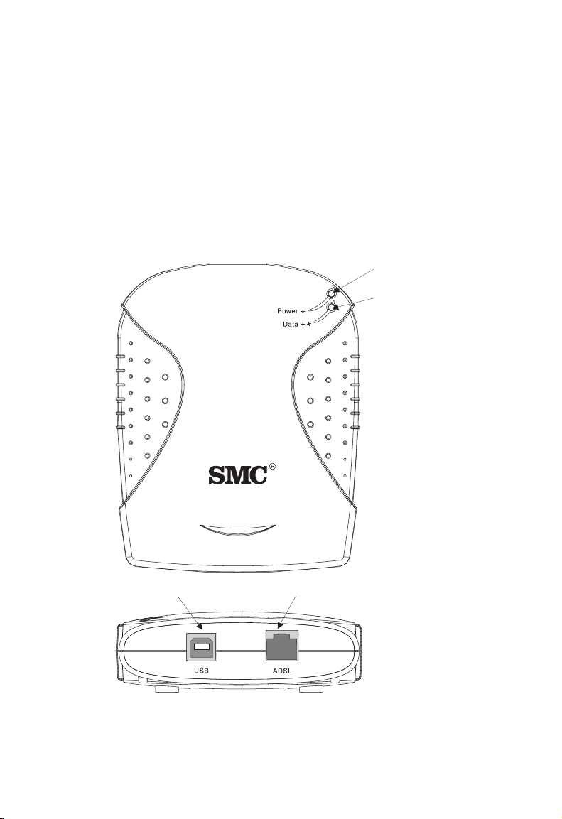
The following figure shows the components of this modem:
Power LED
(Green )
Data LED
(Green)
EZ Connect ADSL/USB Modem
SMC7003USB V.2
USB Port
(Type-B)
Figure 2-1. EZ Connect ADSL USB Modem
2-2
RJ-11 Port
Page 21

H
ARDWARE DESCRIPTION
LED Indicators
The EZ Connect ADSL USB Modem has two LEDs on the top panel, one
is marked “Data” and the other “Power.” The operational status of the
modem is indicated by the LED conditions listed below
LED Status Description
Data Flashing Indicates the modem is synchronizing its ADSL/
ATM link with the head end.
On Indicates an ADSL/ATM link has been established
on the RJ-11 port.
Power On Power is being supplied to the modem via the USB
bus.
.
Power Requirements
USB devices can be either self-powered or bus-powered. A device which
has no power connector is bus-powered, and derives its operating power
from the USB connection directly. The EZ Connect ADSL USB Modem is
bus-powered — all you need to do is plug it into a host PC or self-powered
USB hub.
2-3
Page 22

H
ARDWARE INSTALLATION
System Requirements
The EZ Connect ADSL USB Modem requires the following PC features
to operate:
• A host PC that supports the Universal Serial Bus
• 32 MB of RAM and 10 MB of hard disk space
• Windows 98, 98SE, 2000, XP, or Macintosh 9.x
• Standard telephone cable with RJ-11 plugs
Note: To share Internet access on your network, you will need to install
appropriate Internet-sharing software on one PC.
The ADSL network must meet the following minimum requirements:
• ADSL service from your local telephone company or have access to an
ADSL DSLAM (Digital Subscriber Line Access Multiplexer)
• PC configured with fixed IP address or dynamic IP address assignment
via DHCP, Gateway server address, and DNS server address from
your telephone company or network administrator
2-4
Page 23

C
ONNECTING THE SYSTEM
Connecting the System
Phone Line Configuration
The EZ Connect ADSL USB Modem supports dual-mode operation for
both full-rate G.dmt and economical G.lite. Your service provider will
attach the outside ADSL line to a data/phone splitter. You can then
connect your phones and computer directly to the splitter as shown below:
Plain Old
Telephone
System (POTS)
Residential
Connection
Point [Network
Interface
Device (NID)]
Voice
Splitter
SMC7003USB V.2
Data
Depending on the wiring configuration used in your house, separate wall
jacks may be used for telephone and voice signals. Otherwise, you will
need to connect your phones and PC directly to the splitter.
1. Connect the modem’s ADSL port to the data port on the splitter (or
to an RJ-11 telephone wall jack connected to this port) using standard
telephone cable.
2. Insert the USB cable’s Type-B plug (square end) into the modem’s
USB port.
3. Install the driver best suited for your connection needs as described in
the next chapter.
2-5
Page 24

H
ARDWARE INSTALLATION
2-6
Page 25

C
HAPTER
D
RIVER INSTALLATION
The CD supplied with the package contains the software drivers available
for the EZ Connect ADSL USB Modem.
Note: DO NOT plug the device to your computer directly before driver
installation. Follow the instructions to install the driver and
connect the modem properly.
This modem is fully software upgradeable so that new features and
updates may be added by simply loading a new version of the device driver
onto your PC. New or updated drivers can be downloaded from SMC’s
Web site at:
http://www.smc.com
Note: Updating to a new version of the software requires removal of the
currently installed version, go to “Upgrading the Modem
Software” on page 6-1 for a detailed description.
3
3-1
Page 26

D
RIVER INSTALLATION
Windows 98/98SE/2000/XP
You may find that the instructions here do not exactly match your version
of Windows. This is because these steps and screenshots were created
from Windows 2000. The installation of Windows 98, 98SE and XP are
similar, but not identical, to Windows 2000.
Follow the instructions below to begin the driver installation:
1. Disconnect the EZ Connect ADSL USB Modem with your computer.
2. Insert the CD-ROM that comes with the modem into your CD drive.
The Installation Wizard screen will appear. Click Install SMC 7003
ADSL USB Modem Driver.
3-2
Page 27

W
INDOWS
3. The Welcome screen will open. Click Next to continue.
4. After viewing the license agreement, click Accept.
98/98SE/2000/XP
3-3
Page 28

D
RIVER INSTALLATION
5. During installation, the system will display a screen to ask you to plug
in the modem. Plug in the device now.
Note: Connect the SMC7003USB V.2 to the computer using the
supplied USB cable. Insert the rectangular end (Type-A) of the
USB cable into the USB port of your PC. Insert the square end
(Type-B) of the cable into the USB port of the USB modem.
6. After the driver files have been installed, you will be asked to reboot
the computer. Check “Yes, reboot the computer now” and click Close.
3-4
Page 29

W
INDOWS
7. After your computer restarts, the “Finished” screen will appear to
indicate successful completion of the installation process. Click Finish.
Note: Regardless of the driver type installed, the installation procedure
will automatically configure the TCP/IP settings to acquire IP
addressing information from the service provider via DHCP.
98/98SE/2000/XP
3-5
Page 30

D
RIVER INSTALLATION
Macintosh 9.x
1. Start up your PC with the modem connected.
2. Insert the CD-ROM that comes with the EZ Connect ADSL USB
Modem into your CD drive.
3. Select the language version you want to install, and double-click to
open the chosen folder.
4. Double-click Installer to start driver installation.
3-6
Page 31

M
ACINTOSH
5. The Welcome screen will appear as shown on below; click Continue.
6. Select the location to install the software, and click Select.
9.
X
3-7
Page 32

D
RIVER INSTALLATION
7. Click Start to continue.
8. Click Quit to finish driver installation.
3-8
Page 33

Uninstallation in Macintosh 9.x
1. If you want to uninstall the driver and SMC7003USB control panel,
insert the CD-ROM that comes with the modem into your CD drive.
Then repeat step 3 to step 6 in the previous section.
2. Choose Customized Removal and click Start to continue.
3. Select All and click OK.
M
ACINTOSH
9.
X
3-9
Page 34

D
RIVER INSTALLATION
4. Click Quit to close the window.
3-10
Page 35

C
HAPTER
4
TCP/IP N
Microsoft Windows 98/98SE
TCP/IP settings are automatically set up during the software installation
process. The following procedure may be used to change TCP/IP settings,
if necessary.
1. From your PC desktop, double-click the My Computer icon.
2. From the My Computer window, double-click the Dial-Up
Networking icon.
3. From the Dial-Up Networking window, right-click the SMC ADSL
Connection icon and click Properties.
ETWORKING
O
PTIONS
Note: The icon name may differ from that specified above. The SMC
connection will be identified as “DSLAtmUsb-Line0” in the
Device Name from the Dial-Up Networking window.
4-1
Page 36

TCP/IP N
ETWORKING OPTIONS
4. From the Server Types tab of the SMC Dial-Up PPP Connection
window, select the TCP/IP checkbox and click TCP/IP Settings.
4-2
Page 37

M
ICROSOFT WINDOWS
5. The TCP/IP Settings window will appear for you to modify the IP
address, Name Server addresses and/or default gateway.
Note: Please fill in the information provided by your Internet Service
Provider on the above screen.
98/98SE
6. Click OK.
7. The SMC Dial-Up PPP Connection window will reappear. Click OK
to close the window.
4-3
Page 38

TCP/IP N
ETWORKING OPTIONS
Microsoft Windows 2000
TCP/IP settings are automatically set up during the software installation
process. The following procedure may be used to change TCP/IP settings,
if necessary.
1. From your PC desktop, click Start/Settings/Network and Dial-Up
Connections.
2. From the Network and Dial-Up Connections window, right-click SMC
Dial-Up PPP Connection and select Properties.
Note: The icon name may differ from that specified above. The SMC
connection will be identified as “DSLAtmUsb-Line0” in the
Device Name from the Dial-Up Networking window.
4-4
Page 39

M
ICROSOFT WINDOWS
3. From the Networking tab of the SMC Dial-Up PPP Connection
Properties window, select Internet Protocol (TCP/IP) and click
Properties.
98/98SE
4-5
Page 40

TCP/IP N
ETWORKING OPTIONS
4. The Internet Protocol (TCP/IP) Properties window will appear for
you to modify the IP address and DNS Server addresses.
Note: Please fill in the information provided by your Internet Service
Provider on the above screen.
5. Click OK.
6. The SMC Dial-Up PPP Connection Properties window will reappear.
Click OK to close the window.
4-6
Page 41

M
ICROSOFT WINDOWS
Microsoft Windows XP
TCP/IP settings are automatically set up during the software installation
process. The following procedure may be used to change TCP/IP settings,
if necessary.
1. Click Start/Control Panel.
2. Click Network and Internet Connections.
XP
3. The Network Connections window will open as shown above.
Double-click the connection for this device. On the connection status
screen, click Properties.
4-7
Page 42

TCP/IP N
ETWORKING OPTIONS
4. Double-click Internet Protocol (TCP/IP).
5. Fill in the information provided by your Internet Service Provider. Use
the spaces on the next page to record the TCP/IP settings.
4-8
Page 43

M
ICROSOFT WINDOWS
6. Select “Obtain an IP address automatically” and “Obtain DNS server
address automatically.” Click OK or Close to close each window.
TCP/IP Configuration Setting
IP Address ____.____.____.____
Subnet Mask ____.____.____.____
Default Gateway ____.____.____.____
Preferred DNS Server ____.____.____.____
Alternate DNS Server ____.____.____.____
Obtain IP Settings from Your Modem
Now that you have configured your computer to connect to your modem,
it needs to obtain new network settings. By releasing old DHCP IP settings
and renewing them with settings from your modem, you can verify that
you have configured your computer correctly.
1. From the Windows desktop, click Start/Programs/Accessories/
Command Prompt.
XP
4-9
Page 44

TCP/IP N
ETWORKING OPTIONS
2. In the Command Prompt window, type “IPCONFIG /RELEASE”
and press the ENTER key.
3. Type “IPCONFIG /RENEW” and press the ENTER key. Verify that
your IP Address is now 192.100.100.xxx (where x is 1 - 14,
16 - 254), your Subnet Mask is 255.255.255.0 and your Default
Gateway is 192.100.100.15. These values confirm that your ADSL
Router is functioning.
Type EXIT and press ENTER to close the Command Prompt window.
Your computer is now configured to connect to the modem.
4-10
Page 45

M
ACINTOSH CONFIGURATION
Macintosh Configuration
The following instructions will help you to get your network configuration
information.
Note: Your local ISP will configure your network to the following
settings. If there is any problem with these functions, please
contact your local ISP for help.
ADSL Setup
1. Pull down the Apple Menu.
2. Select Control Panels/ADSL Setup to view SMC ADSL USB Modem
information including DSL Status and System Information.
4-11
Page 46

TCP/IP N
ETWORKING OPTIONS
3. Move the cursor onto the SMC ADSL USB Modem window, and
press the “Ctrl” - “1” keys on your keyboard.
4. The Configuration, ATM, and DSL Advanced information fields will
appear as shown below.
5. Click the button in the top left corner to close this ADSL Setup
window.
4-12
Page 47

M
ACINTOSH CONFIGURATION
TCP/IP
1. Pull down the Apple Menu. Select Control Panels/TCP/IP to view
your TCP/IP information.
2. On the TCP/IP window, make sure “PPP” is selected in the Connect
via: field, and “Using PPP Server” is already selected in the Configure
field.
3. Click the button in the top left corner to close the TCP/IP window.
Modem
1. Pull down the Apple Menu. Select Control Panels/Modem to
configure this device.
2. Set the Connect via field and the Modem field to “ADSL USB
MODEM” on this window.
3. Once you have made these changes, close the Modem Control Panel
and click Save to save your changes.
Remote Access
1. On the control strip located along the bottom of your screen, click
Remote Access/Open Remote Access.
2. Enter the user name and password for the user account you should
have received from your ISP.
3. Key in the Virtual Path Identifier (VPI) and Virtual Channel Identifier
(VCI) (e.g., 0, 33) in Number field.
Note: The VPI and VCI should be provided by your local ISP.
4. Click Connect.
Your computer is now ready to connect to the Internet.
4-13
Page 48

TCP/IP N
ETWORKING OPTIONS
4-14
Page 49

C
HAPTER
C
OMMUNICATION
Dial-Up PPP Connection
Once the SMC ADSL USB Modem and software have been
installed, the SMC Dial-Up PPP Connection icon will
appear on your desktop.
To connect to Internet, double-click the short-cut icon. Fill in the User
name and Password (which should provided by your Internet Service
Provider). Click Dial to start your Internet connection.
S
ETTINGS
5
Note: If you cannot connect to the Internet, go to “Troubleshooting” on
page A-1.
5-1
Page 50

C
OMMUNICATION SETTINGS
Connection Information
The EZ Connect ADSL USB Modem control panel program provides a
quick and easy way to configure and check the performance of the modem
and ADSL connection. When open, the monitor window is updated every
two seconds.
1. On the desktop, click Start/Settings/Control Panel.
2. From the Control Panel window, double-click the SMC DSL Modem
icon to view the configuration settings.
Note: To access the modem, the driver must be running. Also, make sure
the USB cable is plugged into the modem.
5-2
Page 51

C
ONNECTION INFORMATION
Physical Link
The Physical Link screen allows you to review the current state of the EZ
Connect ADSL USB Modem and connection. When the green indicator is
on in the Link Status field, it indicates that a connection has been made.
This indicator blinks while a connection is being established. The
Transmitting and Receiving data activity are shown separately by individual
flashing green indicators.
Click Restart for reconnection, Abort for disconnection, and Advanced to
view detailed information.
5-3
Page 52

C
OMMUNICATION SETTINGS
System Information
The System Information screen displays the release number of the EZ
Connect ADSL USB Modem driver, the firmware release number, and the
control panel version that you are currently using.
5-4
Page 53

C
ONNECTION INFORMATION
Configuration
The Configuration screen displays the modulation settings applicable to
your driver.
If you need to configure further settings, launch the Communication
Settings window by clicking Start/Programs/SMC DSL Modem/
Configure.
5-5
Page 54

C
OMMUNICATION SETTINGS
The Communication Settings window allows you to select the
Encapsulation type of PPPoATM or PPPoE connection, and the
modulation settings.
• Encapsulation (Default: RFC 2364 PPPoATM LLC Encapsulation)
• Modulation (Default: Multimode)
5-6
Page 55

C
HAPTER
U
PGRADING THE
Updating to a new version of the software requires removal of the
currently installed version. Follow the instructions below to uninstall the
current driver version, then go to “Driver Installation” on page 3-1 to
install the updated driver.
Note: DO NOT unplug the USB cable from your computer until the
uninstall process has been completed. For Windows applications,
the cable must be unplugged immediately following Step 3 below.
1. From your PC desktop click Start/Programs/SMC DSL Modem/
Uninstall. A message will be displayed asking you to confirm removal
of the USB ADSL modem software. Click Yes.
M
S
OFTWARE
ODEM
6
6-1
Page 56

U
PGRADING THE MODEM SOFTWARE
2. The Information window will be displayed reminding you not to
unplug the USB cable until the uninstall process has been completed.
Click OK to continue.
3. A message will display indicating that you can unplug the device.
Remove the modem connection now. Then click OK.
6-2
Page 57

U
PGRADING THE MODEM SOFTWARE
4. The Setup Complete window indicates successful completion of the
uninstall process. Click Finish to reboot your computer.
5. After your computer restarts, go to “Driver Installation” on page 3-1
for information on driver installations.
6-3
Page 58

U
PGRADING THE MODEM SOFTWARE
6-4
Page 59

A
PPENDIX
T
ROUBLESHOOTING
Check the following troubleshooting points before contacting SMC
Technical Support.
You Cannot Connect to the Network
• Check the phone and USB cables for wear or loose wires and replace
any defective cables if necessary. Make sure the cable is securely
attached to the modem’s RJ-11 port and that the modem is connected
to your ADSL service provider via an RJ-11 wall socket or splitter.
• If your PPP connection fails to respond, hang up and dial again. PPP
may fail to connect when you first dial in due to synchronization
problems.
• If the Data LED is off, review the driver installation process to be sure
that the driver was correctly installed. Make sure the correct software
driver was installed for your operating system. A failed or aborted
installation may leave some system files or drivers that interfere with a
new installation. If necessary, remove the EZ Connect ADSL USB
Modem driver, and try reinstalling it.
A
You Cannot Connect to the Internet
• Click the Network icon in the Control Panel and enter the required
TCP/IP settings specified by your Internet Service Provider (ISP). Then
reboot your computer to enable the new settings.
A-1
Page 60

T
ROUBLESHOOTING
A-2
Page 61

ADSL Specifications
Standards Conformance
Basic ADSL:
ANSI T1.413 Issue II (full rate ADSL), ITU G.992.1 (G.dmt),
ITU G.992.2 (G.lite), G.994.1 (G.handshake)
Transport Protocols:
RFC 1557 (IP/ATM), RFC 2364 (PPP/ATM)
ATM Attributes:
ATM Transmission Convergence,
ATM Framing (with traffic shaping), ATM SAR/AAL5,
ATM Forum UNI3.1 signalling, ATM UBR Service Class
ADSL Service
Service Type:
Full rate Discrete Multi-Tone ADSL (G.dmt),
and Splitterless ADSL (G.lite)
Data Rate:
G.dmt: 8 Mbps (downstream), 1 Mbps (upstream)
G.lite: 1.5 Mbps (downstream), 512 Kbps (upstream)
Media Type:
Simultaneous data/voice (can coexist with HPNA)
Service Provider:
Digital Subscriber Line Access Multiplexer (DSLAM)
A
PPENDIX
S
PECIFICATIONS
B
B-1
Page 62

S
PECIFICATIONS
Media Connection
USB cable connection to PC -90-ohm shielded USB cable,
max length 5 m (16 ft)
RJ-11 phone wire connection to ADSL provider
PC Requirements
Host Interface:
USB Specification 1.1 or up
System Requirements:
A PC and Windows 98, 98SE, 2000, XP, or Mac OS 9.x
Physical Characteristics
Ports
Upstream: 1 USB Type-B
USB spec. 1.1 differential and bi-directional,
12 Mbps (high-speed device)
Downstream: RJ-11
Phone wire connection to ADSL service provider
LEDs
Power, Data
Dimensions
13.0 x 13.0 x 2.9 cm (5.12 x 5.12 x 1.14 in.)
Weight
150 g (5.29 oz)
Input Power
+5VDC, 500mA (maximum)
(bus powered from USB host controller or hub)
Power Consumption
2.50 Watts maximum (from USB host)
B-2
Page 63

Temp era tu re
Operating 0 to 40 °C (32 to 104 °F)
Storage -40 to 70 °C (-40 to 160 °F)
Humidity
5% to 95% (non-condensing)
Compliances
CE Mark
Emissions
FCC Class B
VCCI Class B
Industry Canada Class B
EN55022 (CISPR 22) Class B
C-Tick - AS/NZS 3548 (1995) Class B
Immunity
IEC 1000-4-2/3/4/6
Safety
UL 60950
EN60950 (TÜV)
CSA 22.2 No. 60950
IEC 60950
S
PECIFICATIONS
Warranty
Limited Lifetime
B-3
Page 64

S
PECIFICATIONS
B-4
Page 65

G
LOSSARY
Asymmetric Digital Subscriber Line (ADSL)
One of four DSL technologies. ADSL is designed to deliver more
bandwidth downstream (from the central office to the customer site) than
upstream. Downstream rates range from 1.5 to 9 Mbps, whereas upstream
bandwidth ranges from 16 to 640 Kbps. ADSL transmissions work at
distances up to 18,000 feet (5,488 meters) over a single copper twisted pair.
Asynchronous Transfer Mode (ATM)
A cell-based connection-oriented data service offering high speed (up to
2.488 Gbps) data transfer. ATM integrates circuit and packet switching to
handle both constant and burst information. Frequently called cell relay.
Bandwidth
The difference between the highest and lowest frequencies available for
network signals. Also synonymous with wire speed, the actual speed of the
data transmission along the cable.
CSMA/CD
CSMA/CD (Carrier Sense Multiple Access/Collision Detect) is a
communication method over shared medium that is employed by Ethernet
and Fast Ethernet.
DSL Access Multiplexer (DSLAM)
A device at a phone company’s central office that links many customer’s
DSL connections to a single high-speed ATM line.
Domain Naming System (DNS)
System used in the Internet for translating names of network nodes into
addresses.
Glossary-1
Page 66

G
LOSSARY
Dynamic Host Configuration Protocol (DHCP)
Issues IP addresses automatically within a specified range to devices such
as PCs when they are first powered on. The device retains the use of the IP
address for a specific license period that the system administrator can
define. DHCP is available as part of the many operating systems including
Microsoft Windows NT Server and UNIX.
Ethernet
A network communication system developed and standardized by DEC,
Intel, and Xerox, using baseband transmission, CSMA/CD access, logical
bus topology, and coaxial cable. The successor IEEE 802.3 standard
provides for integration into the OSI model and extends the physical layer
and media with repeaters and implementations that operate on fiber, thin
coax and twisted-pair cable.
G.dmt
A standard that defines full-rate ADSL, which utilizes Discrete Multi-Tone
(DMT) signaling to transmit data at up to 8 Mbps downstream and 640
Kbps upstream.
G.lite
A standard that defines the more economical splitterless ADSL connection
that transmits data at up to 1.5 Mbps downstream and 512 Kbps upstream.
This ADSL option can be installed without an on-site visit by the service
provider.
IEEE
Institute of Electrical and Electronic Engineers.
IEEE 802.3
Defines carrier sense multiple access with collision detection (CSMA/CD)
access method and physical layer specifications.
Glossary-2
Page 67

IEEE 802.3u
Defines CSMA/CD access method and physical layer specifications for
100BASE-TX Fast Ethernet.
Internet Service Provider (ISP)
A company that provides access to the Internet. This may be your local
telephone company, or a dedicated Internet service company.
Local Area Network (LAN)
A group of interconnected computer and support devices.
LED
Light emitting diode used for monitoring a device or network condition.
Point-to-Point Protocol (PPP)
A protocol that provides router-to-router and host-to-network
connections over both synchronous and asynchronous circuits. PPP is the
successor to SLIP.
Quality of Service (QoS)
A network protocol used to specify a guaranteed throughput level. This
protocol is often used by ATM providers to guarantee their customers a
minimum end-to-end latency.
G
LOSSARY
RFC 1483
An open standard that describes two encapsulation methods for carrying
network interconnect traffic over ATM, specifically LLC/SNAP and VC
multiplexing.
RFC 2364
An open standard that describes how to use ATM for framing PPP
encapsulated packets.
Glossary-3
Page 68

G
LOSSARY
RJ-45 Connector
A connector for twisted-pair wiring.
Splitter
A hardware device used in G.dmt to split the data and voice traffic before
passing it on to the network and phone system.
Transmission Control Protocol/Internet Protocol (TCP/IP)
Protocol suite that includes TCP as the primary transport protocol, and IP
as the network layer protocol.
Transmission Control Protocol (TCP)
A commonly used protocol for establishing and maintaining
communications between applications on different computers. TCP
provides full-duplex, acknowledged, and flow-controlled service to
upper-layer protocols and applications.
UTP
Unshielded twisted-pair cable.
Virtual channel Identifier (VCI)
A 16-bit field in the header of an ATM cell. The VCI, together with VPI,
is used to identify the next destination of a cell as it passes through a series
of ATM switches on its way to its destination.
Virtual Path Identifier (VPI)
A 8-bit field in the header of an ATM cell.
Glossary-4
Page 69

Page 70

FOR TECHNICAL SUPPORT, CALL:
From U.S.A. and Canada (24 hours a day, 7 days a week)
(800) SMC-4-YOU; (949) 679-8000; Fax: (949) 679-1481
From Europe (8:00 AM - 5:30 PM UK Time)
44 (0) 118 974 8700; Fax: 44 (0) 118 974 8701
INTERNET
E-mail addresses:
techsupport@smc.com
european.techsupport@smc-europe.com
support@smc-asia.com
Driver updates:
http://www.smc.com/index.cfm?action=tech_support_drivers_downloads
World Wide Web:
http://www.smc.com
http://www.smc-europe.com
http://www.smc-asia.com
FOR LITERATURE OR ADVERTISING RESPONSE, CALL:
U.S.A. and Canada: (800) SMC-4-YOU; Fax (949) 679-1481
Spain: 34-93-477-4935; Fax 34-93-477-3774
UK: 44 (0) 1932 866553; Fax 44 (0) 118 974 8701
France: 33 (0) 41 38 32 32; Fax 33 (0) 41 38 01 58
Italy: 39 (0) 335 5708602; Fax 39 02 739 14 17
Benelux: 31 33 455 72 88; Fax 31 33 455 73 30
Central Europe: 49 (0) 89 92861-0; Fax 49 (0) 89 92861-230
Nordic: 46 (0) 868 70700; Fax 46 (0) 887 62 62
Eastern Europe: 34 -93-477-4920; Fax 34 93 477 3774
Sub Saharian Africa: 27 0126610232; Fax 27-11 314 9133
North West Africa: 216 71236616; Fax 216 71751415
CIS: 7 (095) 789 35 73; Fax 7 (095) 789 35 73
PRC (Beijing): 86-10-8251-1550; Fax 86-10-8251-1551
PRC (Shanghai): 86-21-6485-9922; Fax 86-21-6495-7924
Taiwan: 886-2-8797-8006; Fax 886-2-8797-6288
Asia Pacific: (65) 6 238 6556; Fax (65) 6 238 6466
Korea: 82-2-553-0860; Fax 82-2-553-7202
Japan: 81-3-5645-5715; Fax 81-3-5645-5716
Australia: 61-2-8875-7887; Fax 61-2-8875-7777
India: 91 22 5696 2790; Fax 91 22 5696 2794
Middle East: 97 14 299 4466 Fax 97 14 299 4664
Thailand: 66 2 651 8733 Fax 66 2 651 8737
If you are looking for further contact information, please visit www.smc.com,
www.smc-europe.com, or www.smc-asia.com.
38 Tesla
Irvine, CA 92618
Phone: (949) 679-8000
Model Number: SMC7003USB V.2
Pub. Number: 150000039500A E042003-R01
 Loading...