

SMC Networks SMC20TA-2500 PPM Instruction Manual
PERFECT FOR MINERAL POOLS
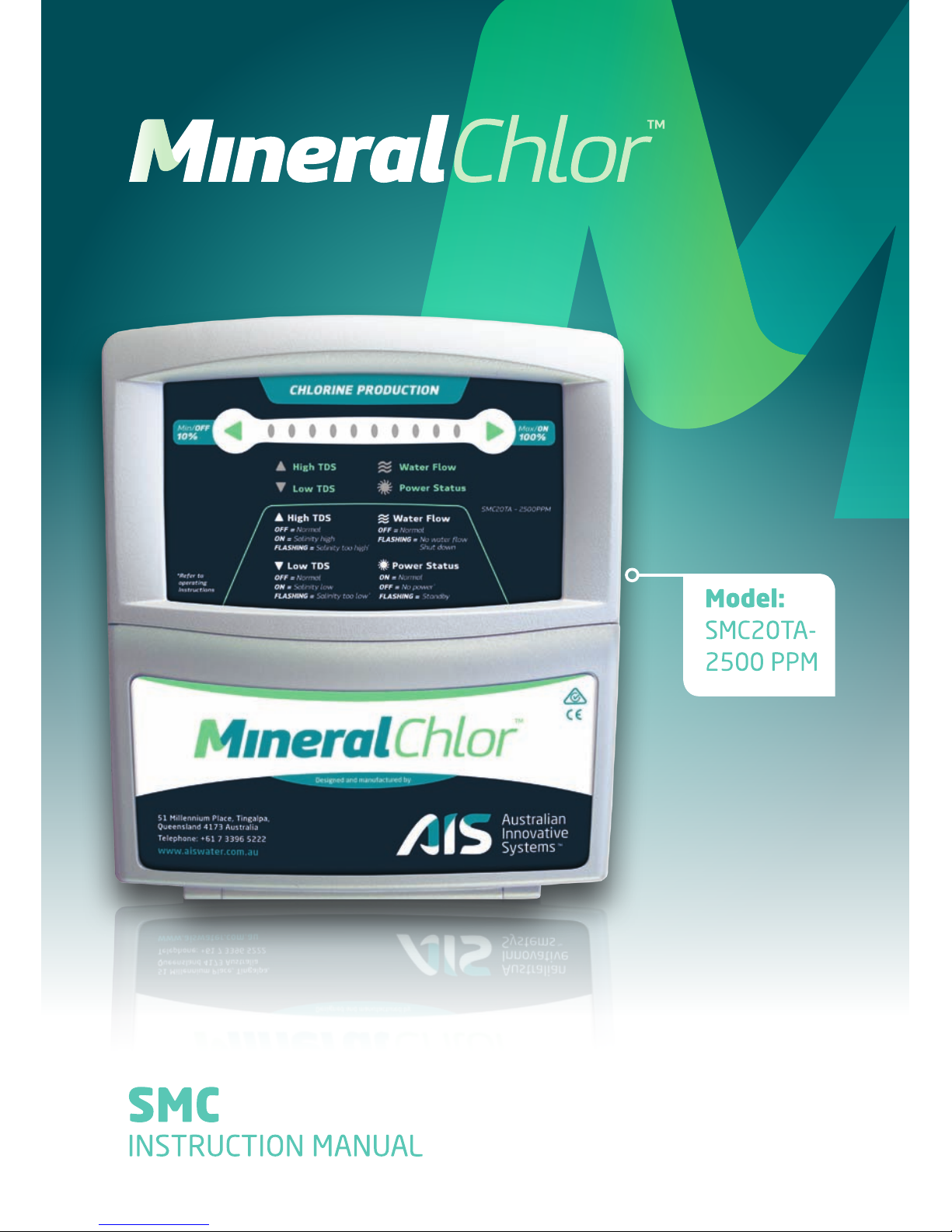
SMC
INSTRUCTION MANUAL
Model:
SMC20TA-
2500 PPM
TM

DISCLAIMER
• While every eort has been made to ensure that the information contained in this guide
is accurate and complete, no liability can be accepted for any errors or omissions.
• Australian Innovative Systems Pty Ltd reserves the right to change the specications
of the hardware and software described herein at any time without prior notice.
• No part of this guide may be reproduced, transmitted, transcribed, stored in a retrieval system,
or translated into any language in any form, by any means, without the prior written permission
of Australian Innovative Systems Pty Ltd.
• Australian Innovative Systems makes no warranties for damages resulting from lack of supply
of chlorine due to a mistaken operation or malfunction of the chlorine generator or use of non
genuine replacement parts.
TRADEMARK ACKNOWLEDGEMENTS
MineralChlor
™
is a trademark of Australian Innovative Systems Pty Ltd
USE OF GENUINE AUSTRALIAN INNOVATIVE SYSTEMS REPLACEMENT PARTS IS RECOMMENDED.
This product is designed to perform optimally when used with genuine Australian Innovative Systems
replacement parts. Australian Innovative Systems Pty Ltd shall not be liable for any damages to this
product caused by the use of non-genuine replacement parts (e.g. electrode.). Please note that this
warranty does not apply to repairs arising out of the malfunction of non-genuine replacement parts,
although you may request such repairs on a chargeable basis.
PURCHASED FROM:
PURCHASED DATE:
NOTE: Proof of purchase / installation is required for warranty claims. Please keep your records in a safe place.
1
TM
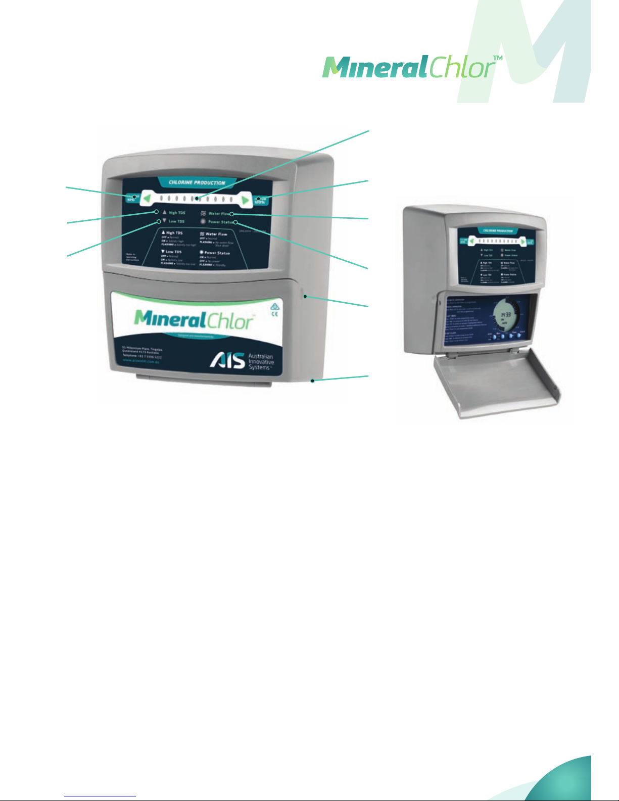
1. Min/O
Press to reduce the chlorine output.
When no lights are lit, the chlorine
generator is o.
2. Max/On
Press to turn on and increase the
chlorine output.
3. Chlorine Production
Each light represents 10% of output
i.e. 5 lights = 50% output.
4. High TDS (Total Dissolved Solids)
If light on or ashing see
Troubleshooting Guide, pages 14–15.
5. Low TDS (Total Dissolved Solids)
If light on or ashing see
Troubleshooting Guide, pages 14–15.
6. Water Flow
If light ashes and chlorine generator
beeps then no water is owing through
the electrode housing.
See Troubleshooting Guide, pages 14–15.
7. Power Status
When light is on the chlorine
generator power supply is operating.
8. To Access Time Clock
Pull forward at these points and
door will fold down.
9. Pump Outlet Socket
The three pin plug supplying power
to the pump is connected here.
1
4
5
3
6
7
9
8
2
2
CHLORINE GENERATOR INSTALLATION
ELECTRODE HOUSING
The electrode housing may be installed either horizontally or vertically in the return water
line to the pool. The water ow through the housing may be in either direction. Plumbing
may be either 40mm or 50mm pipe.
Horizontal - the plumbing connection on the side of the electrode housing must
face downwards.
Vertical - the plumbing connection on the end of the electrode housing must
face downwards and the electrical connections must be protected from the
weather. The electrode housing should be installed in a weatherproof, well
ventilated pool shed.
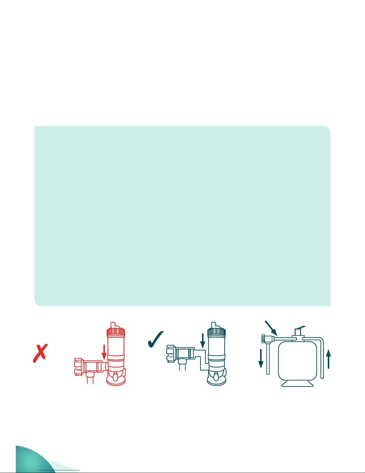
Gas trap - the electrode housing must be installed to form a gas trap as shown
below. If water was to stop owing and the chlorine generator continue running,
chlorine gas pressure will build up in the housing and pipe work and cause damages.
This can happen if water continues to run back into the electrode housing (e.g.
from a outgoing pipe after the pump is turned o), allowing water to come in
contact with the electrodes producing a build-up of gas. A gas trap allows the gas
to displace water away from the sensor terminal, thus turning o the Chlorine
generator power supply and the “water ow” alarm will sound.
GAS TRAP
NO GAS TRAP
OK
3
TM
The power supply should be installed in a weatherproof, well ventilated area and mounted
vertically within 1.5 metres of the electrode. Although the unit has an IP24 rating it can still
be susceptible to wind driven rain.
The SMC chlorine generator can be tted to pools with any type of heating system. Do
not install chlorine generator and water heater in reverse as the heavily chlorinated water
could damage the heating unit and may negate the heater warranty.
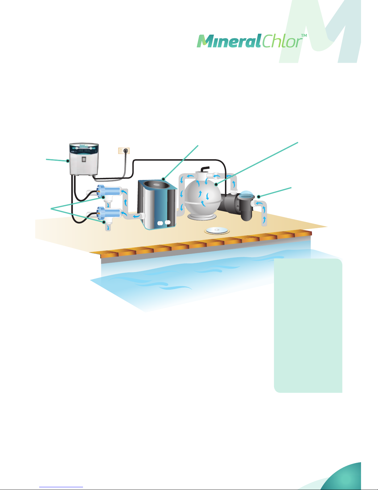
INSTALLATION WITH POOL HEATER
Max/ OnMin/ On
Water Flow
Power Status
High Salt
Low Salt
4
5
3
1
2
1. Pump
2. Filter
3. Water heater
4. Power supply
for chlorine
generator
5. Chlorine
generator
electrode
4
 Loading...