

SMC Networks SJ2000 Series,SJ3000 Series Operation Manual
Doc. No.SJ2000-OMM0001
4 Port Solenoid Valve
PRODUCT NAME
SJ2000/3000 Series
MODEL/ Series

Contents
Safety Instructions ---------------------------------------------------------------------------- 2, 3
Precautions on Design / Selection ------------------------------------------------------- 4, 5
Mounting ---------------------------------------------------------------------------------------- 6
Piping -------------------------------------------------------------------------------------------- 6
Wiring -------------------------------------------------------------------------------------------- 6
Lubrication -------------------------------------------------------------------------------------- 6
Air Supply --------------------------------------------------------------------------------------- 7
Operating Environment ---------------------------------------------------------------------- 7
Maintenance ------------------------------------------------------------------------------------ 7
Specific Product Precautions --------------------------------------------------------------- 8 to 13
Troubleshooting -------------------------------------------------------------------------------- 14
Remedy ------------------------------------------------------------------------------------------ 15
-1-
SJ2000-OMM0001
Safety Instructions
These safety instructions are intended to prevent hazardous situations and/or equipment damage.
These instructions indicate the level of potential hazard with the labels of “Caution,” “Warning” or “Danger.”
They are all important notes for safety and must be followed in addition to International Standards (ISO/IEC),
Japan Industrial Standards (JIS)*1) and other safety regulations*2).
*1) ISO 4414: Pneumatic fluid power -- General rules relating to systems
ISO 4413: Hydraulic fluid power -- General rules relating to systems
IEC 60204-1: Safety of machinery -- Electrical equipment of machines (Part 1: General requirements)
ISO 10218-1992: Manipulating industrial robots -- Safety
JIS B 8370: General rules for pneumatic equipment.
JIS B 8361: General rules for hydraulic equipment.
JIS B 9960-1: Safety of machinery – Electrical equipment for machines. (Part 1: General requirements)
JIS B 8433-1993: Manipulating industrial robots - Safety. etc.
*2) Labor Safety and Sanitation Law, etc.
Caution
Warning
Danger
Operator error could result in injury or equipment damage.
Operator error could result in serious injury or loss of life.
In extreme conditions, there is a possibility of serious injury or loss of life.
Warning
1. The compatibility of the product is the responsibility of the person who designs the equipment or
decides its specifications.
Since the product specified here is used under various operating conditions, its compatibility with specific
equipment must be decided by the person who designs the equipment or decides its specifications based on
necessary analysis and test results.
The expected performance and safety assurance of the equipment will be the responsibility of the person who
has determined its compatibility with the product.
This person should also continuously review all specifications of the product referring to its latest catalog
information, with a view to giving due consideration to any possibility of equipment failure when configuring the
equipment.
2. Only personnel with appropriate training should operate machinery and equipment.
The product specified here may become unsafe if handled incorrectly.
The assembly, operation and maintenance of machines or equipment including our products must be
performed by an operator who is appropriately trained and experienced.
3. Do not service or attempt to remove product and machinery/equipment until safety is confirmed.
The inspection and maintenance of machinery/equipment should only be performed after measures to prevent
falling or runaway of the driven objects have been confirmed.
When the product is to be removed, confirm that the safety measures as mentioned above are implemented
and the power from any appropriate source is cut, and read and understand the specific product precautions
of all relevant products carefully.
Before machinery/equipment is restarted, take measures to prevent unexpected operation and malfunction.
4. Contact SMC beforehand and take special consideration of safety measures if the product is to
be used in any of the following conditions.
1) Conditions and environments outside of the given specifications, or use outdoors or in a place exposed to
direct sunlight.
2) Installation on equipment in conjunction with atomic energy, railways, air navigation, space, shipping,
vehicles, military, medical treatment, combustion and recreation, or equipment in contact with food and
beverages, emergency stop circuits, clutch and brake circuits in press applications, safety equipment or other
applications unsuitable for the standard specifications described in the product catalog.
3) An application which could have negative effects on people, property, or animals requiring special safety
analysis.
4) Use in an interlock circuit, which requires the provision of double interlock for possible failure by using a
mechanical protective function, and periodical checks to confirm proper operation.
- 2 -
SJ2000-OMM0001

Safety Instructions
Caution
The product is provided for use in manufacturing industries.
The product herein described is basically provided for peaceful use in manufacturing industries.
If considering using the product in other industries, consult SMC beforehand and exchange specifications
or a contract if necessary.
If anything is unclear, contact your nearest sales branch.
Limited warranty and Disclaimer/Compliance Requirements
The product used is subject to the following “Limited warranty and Disclaimer” and “Compliance
Requirements”.
Read and accept them before using the product.
Limited warranty and Disclaimer
The warranty period of the product is 1 year in service or 1.5 years after the product is delivered.*3)
Also, the product may have specified durability, running distance or replacement parts. Please
consult your nearest sales branch.
For any failure or damage reported within the warranty period which is clearly our responsibility, a
replacement product or necessary parts will be provided.
This limited warranty applies only to our product independently, and not to any other damage
incurred due to the failure of the product.
Prior to using SMC products, please read and understand the warranty terms and disclaimers noted
in the specified catalog for the particular products.
*3)
A vacuum pad is a consumable part, so it is warranted for a year after it is delivered.
Also, even within the warranty period, the wear of a product due to the use of the vacuum pad or
Vacuum pads are excluded from this 1 year warranty.
failure due to the deterioration of rubber material are not covered by the limited warranty.
Compliance Requirements
When the product is exported, strictly follow the laws required by the Ministry of Economy, Trade and
Industry (Foreign Exchange and Foreign Trade Control Law).
- 3 -
SJ2000-OMM0001
SJ2000/3000 Series
Precautions for 4 Port Solenoid Valve ①①①①
Be sure to read before handling.
Design / Selection
Warning
1. Confirm the specifications.
Products represented in this manual are designed only for use in
compressed air systems (including vacuum).
Do not operate at pressures or temperatures, etc., beyond the
range of specifications, as this can cause damage or
malfunction. (Refer to the specifications.)
Please contact SMC when using a fluid other than compressed
air (including vacuum).
We do not guarantee against any damage if the product is used
outside of the specification range.
2. Actuator drive
When an actuator, such as a cylinder, is to be driven using a
valve, take appropriate measures (cover installation or approach
prohibition) to prevent potential danger caused by actuator
operation.
3. Intermediate stops
For 3-position closed center type, it is difficult to make a piston
stop at the required position accurately due to the
compressibility of air.
Furthermore, since valves and cylinders are not guaranteed for
zero air leakage, it may not be possible to hold a stopped
position for an extended period of time.
Please contact SMC if it is necessary to hold a stopped position
for an extended period of time.
4. Effect of back pressure
When the air operated valve or single acting cylinder is
operated, they may malfunction due to the exhaustion of other
actuator. If back pressure is possible to be present, use the
valve with back pressure prevention valve, or use air SUP./EXH.
block assembly and EXH. block disk to divide air exhaustion.
5. Holding pressure (including vacuum)
Since the valves are subject to air leakage, they cannot be used
for applications such as holding pressure (including vacuum) in
a pressure vessel.
6. Not suitable for use as an emergency shutoff valve,
etc.
The valves listed in this manual are not designed for safety
applications such as an emergency shutoff valve. If the valves
are used for the mentioned applications, additional safety
measures should be adopted.
7. Release of residual pressure
For maintenance purposes install a system for releasing
residual pressure. Especially in the case of 3-position closed
center valve type, ensure that the residual pressure between the
valve and the cylinder is released.
8. Operation in a vacuum condition
When a valve is used for switching a vacuum, take measures to
install a suction filter or similar to prevent external dust or other
foreign matter from entering inside the valve.
In addition, at the time of vacuum adsorption, be sure to vacuum
at all times. Failure to do so may result in foreign matter sticking
to the adsorption pad, or air leakage causing the workpiece to
drop.
9. Regarding a vacuum switch valve and a vacuum
release valve
If a non-vacuum valve is installed in the middle of piping system
having a vacuum, the vacuum condition will not be maintained.
Use a valve designed for use under vacuum condition.
10. Double solenoid type
When using the double solenoid type for the first time, actuators
may travel in an unexpected direction depending on the
switching position of the valve. Implement measures to prevent
any danger from occurring when operating the actuator.
11. Ventilation
Provide ventilation when using a valve in a confined area, such
as in a closed control panel. For example, install a ventilation
opening, etc. in order to prevent pressure from increasing inside
of the confined area and to release the heat generated by the
valve.
12. Extended periods of continuous energization
- If a valve will be continuously energized for an extended period
of time, the temperature of the valve will increase due to the
heat generated by the coil. This will likely adversely affect the
performance of the solenoid valve and any nearby peripheral
equipment. Therefore, when it is continuously energized or the
energized period per day is longer than the de-energized
period use the valve with a power saving circuit. In addition, it is
possible to shorten the energized time by making a valve with
an N.O. (normally open) specification.
- For applications such as mounting a valve on a control panel,
incorporate measure to limit the heat radiation so that the
temperature will be high when a 3 station manifold.
13. Do not disassemble the product or make any
modifications, including additional machining.
It may cause human injury and/or an accident.
Caution
1. Momentary energization
If a double solenoid valve is operated with momentary
energization, it should be energized for at least 0.1 second.
However, depending on the condition of the secondary load, it
should be energized until the cylinder reaches the stroke end
position, since there is a possibility of malfunction.
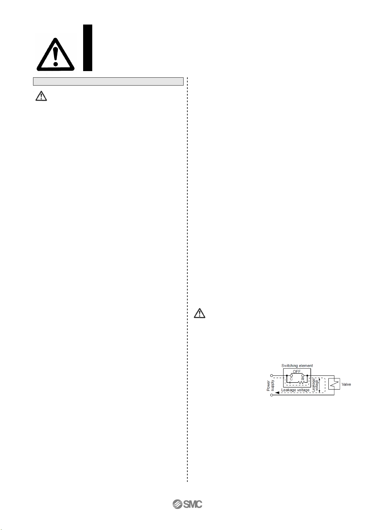
2. Leakage voltage
Take note that the leakage
voltage will increase when
a resistor is used in parallel
with switching element or a
C-R circuit (surge voltage suppressor) is used for protecting a
switching device because of the passing leakage voltage
through the C-R circuit. The suppressor residual leakage
voltage should be 3% or less of the rated voltage.
3. Surge voltage suppressor
If a surge protection circuit contains nonstandard diodes, such
as Zener diodes or varistor, a residual voltage that is in
proportion to the protective circuit and the rated voltage will
remain. Therefore, take into consideration the surge voltage
protection of the controller.
In the case of diodes, the residual voltage is approximately 1 V.
- 4 -
SJ2000-OMM0001
SJ2000/3000 Series
Precautions for 4 Port Solenoid Valve ②②②②
Be sure to read before handling.
Design / Selection
Caution
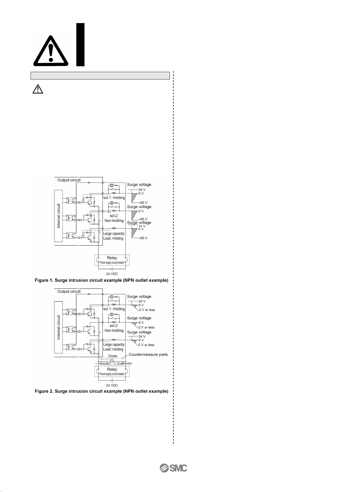
4. Surge voltage intrusion
With non-polar type solenoid valves, at times of sudden
interruption of the loading power supply, such as emergency
shutdown, surge voltage intrusion may be generated from
loading equipment with a large capacity (power consumption),
and the solenoid valve in a de-energized state may switch over
(see Figure 1).
When installing a breaker circuit for the loading power supply,
consider using a solenoid valve with polarity (with polarity
protection diode), or install a surge absorption diode between
the loading equipment COM line and the output equipment
COM line (see Figure 2).
5.
Operation in a low temperature condition
It is possible to operate a valve in extreme temperature, as low
as -10oC. Take appropriate measures to avoid freezing of
drainage, moisture etc. in low temperature.
6.
Operation for air blowing
When using a solenoid valve for air blowing, use an external
pilot type.
Use caution because the pressure drop caused by the air
blowing can have an affect on the internal pilot type valve when
the internal pilot type valves and external pilot type valves are
used on the same manifold.
Additionally, when compressed air within the pressure range of
the established specifications is supplied to the external pilot
type valve’s port, and a double solenoid valve is used for air
blowing, the solenoids should normally be energized when air is
being blown.
7. Mounting orientation
Mounting orientation is free.
- 5 -
SJ2000-OMM0001
 Loading...