

SMC Networks SGH100, SGH200, SGH300, SGH400 Installation And Maintenance Manual
SGH100-TFM86
Installation and Maintenance Manual
Coolant Valve
Series : SGH100/200/300/400
1 Safety Instructions
• This manual contains essential information for the protection of users
and others from possible injury and/or equipment damage.
• Read this manual before using the product, to ensure correct handling,
and read the manuals of related apparatus before use.
• Keep this manual in a safe place for future reference.
• These instructions indicate the level of potential hazard by label of
“DANGER”, “WARNING” or “CAUTION”, followed by important safety
information which must be carefully followed.
• To ensure safety of personnel and equipment the instructions in this
manual and the product catalogue must be observed, along with other
relevant safety practices.
WARNING
• The compatibility of pneumatic equipment is the responsibility of
the person who designs the pneumatic system or decides its
specifications.
Since the product specified here is used under various operating
conditions, its compatibility with specific equipment must be decided by
the person who designs the equipment or decides its specifications
based on necessary analysis and test results. The expected
performance and safety assurance of the equipment will be the
responsibility of the person who has determined its compatibility with
the product. This person should also continuously review all
specifications of the product referring to its latest catalog information,
with a view to giving due consideration to any possibility of equipment
failure when configuring the equipment.
• Only trained personnel should operate pneumatically operated
machinery and equipment.
The product specified here may become unsafe if handled incorrectly.
The assembly, operation and maintenance of machines or equipment
including our products must be performed by an operator who is
appropriately trained and experienced.
• Do not service machinery/equipment or attempt to remove
components until safety is confirmed.
1) The inspection and maintenance of machinery/equipment should
only be performed after measures to prevent falling or prevention of
the danger by the fluid have been confirmed.
2) When the product is to be removed, confirm that the safety measures
as mentioned above are implemented and the power from any
appropriate source is cut, and read and understand the specific
product precautions of all relevant products carefully.
3) Before machinery/equipment is restarted, take measures to prevent
unexpected operation and malfunction.
• Contact SMC beforehand and take special consideration of safety
measures if the product is to be used in any of the following
conditions.
1) Conditions and environments beyond the given specifications, or if
product is used outdoors or with direct sunlight.
2) With fluids whose application causes concern due to the type of fluid
or additives, etc.
1 Safety Instructions (continued)
3) An application that has the possibility of having negative effects on
people, property, or animals, requiring special safety analysis.
1. The product is provided for use in manufacturing industries.
The product herein described is basically provided for peaceful use in
manufacturing industries.
If considering using the product in other industries, consult SMC
beforehand and exchange specifications or a contract if necessary.
If anything is unclear, contact your nearest sales branch.
Limited warranty and Disclaimer/Compliance Requirements
The product used is subject to the following “Limited warranty and
Disclaimer” and “Compliance Requirements”.
Read and accept them before using the product.
Limited warranty and Disclaimer
1. The warranty period of the product is 1 year in service or 1.5 years after
the product is delivered.
*3
)
Also, the product may have specified durability, running distance or
replacement parts. Please consult your nearest sales branch.
2. For any failure or damage reported within the warranty period which is
clearly our responsibility, a replacement product or necessary parts will
be provided. This limited warranty applies only to our product
independently, and not to any other damage incurred due to the failure
of the product.
3. Prior to using SMC products, please read and understand the warranty
terms and disclaimers noted in the specified catalog for the particular
products.
*3) Vacuum pads are excluded from this 1 year warranty.
A vacuum pad is a consumable part, so it is warranted for a year after it
is delivered. Also, even within the warranty period, the wear of a product
due to the use of the vacuum pad or failure due to the deterioration of
rubber material are not covered by the limited warranty.
CAUTION
• Ensure that the air supply system is filtered to 5 micron.
2 Specifications
2.1 Valve specifications
Note :
Impact resistance: No malfunction occurred when it was tested with a drop
tester in the axial direction and at right angles to the main valve & armature;
in both energized & de-energised states and for every time in each condition
(Values at the initial period.)
Vibration resistance: No malfunction occurred in a one-sweep test between
45 and 2000 Hz. Tests ere performed at both energized and de-energized
states in the axial direction and at right angles to the main valve & armature.
(Valves at the initial period.)
2.2 Solenoid Specifications
2 Specifications (continued)
Note) In common between 110 VAC and 115 VAC, and between 220 VAC and 230 VAC.
For 115 VAC and 230 VAC, the allowable voltage is -15% to +5% of rated
voltage.
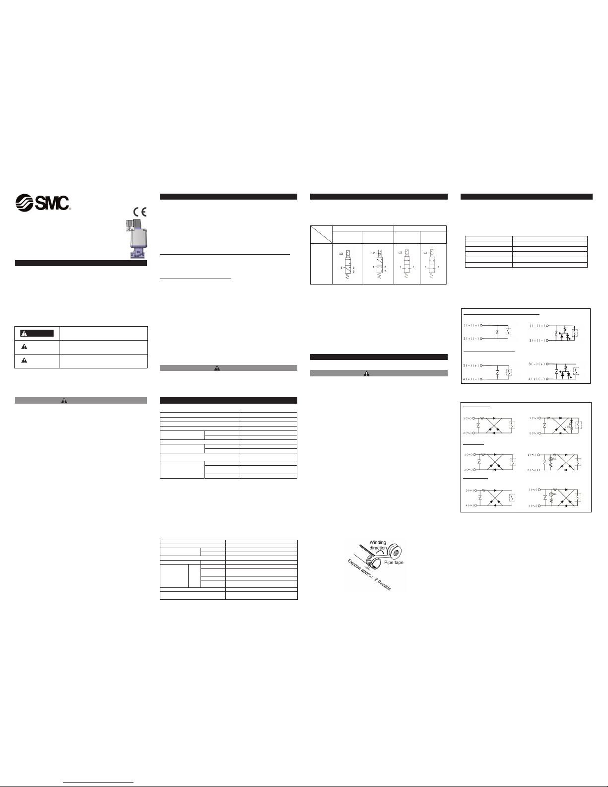
2.3 Circuit symbol
Note)
The Reverse pressurization type valve can be used as a N.C. valve or as a Selector
valve.See below for piping method:
• N.C. valve use 1 port : output port
2 port : waste fluid port
3 port : supply port
• Selector valve use 1 port : output port
2 port : low pressure supply port
3 port : high pressure supply port
3 Installation
3.1 Environment
WARNING
1. Do not use in an environment where the product is directly exposed to
corrosive gases, chemicals, salt water, water or steam.
2. Products with IP65 and IP67 enclosures (based on IEC60529) are
protected against dust and water, however, these products cannot be used
in water.
3. Incorrect mounting of the product violates the IP65 rating. Be sure to read
the Precautions for each product.
4. Do not use in explosive atmospheres.
5. The product should not be exposed to prolonged sunlight.Use a protective
cover.
6. Do not mount the product in a location where it is subject to strong
vibrations and/or shock. Check the product specifications.
7. Remove emissive heat.
8. If using in an atmosphere where there is possible contact with water
drop-lets, oil, weld spatter, etc., take suitable preventative measures.
9. When the product is mounted in a control panel, or when it's energized for
a long time, make sure that the ambient temperature is within the specified
range.
3.2 Piping
1. Preparation before piping
Before piping is connected, it should be thoroughly blown out with air
(flushing) or washed to remove chips, cutting oil and other debris from
inside the pipe.
Install piping so that it does not apply pulling, pressing, bending or other
forces the valve body.
2. Sealant tape
When installing piping or fitting into a port, ensure that sealant material
does not enter the port internally. Furthermore, when sealant tape is
used, leave 1.5 to 2 thread ridges exposed at the end of the threads.
<For AC>
3 Installation (continued)
3. Avoid connection of ground lines to piping, as this may cause electric
corrosion of the system.
4. Always tighten threads with the proper tightening torques.
When screwing fittings into valves, tighten with the proper tightening
torque shown below.
Tightening Torque for Piping
5. Connection of piping to products.
When connecting piping to a product, avoid mistakes regarding the
supply port, etc.
3.3 Light/Surge Voltage Suppressor
<For DC>
In extreme conditions, there is a possibility of
serious injury or loss of life.
WARNING
If instructions are not followed there is a
possibility of serious injury or loss of life.
CAUTION
If instructions are not followed there is a
possibility of injury or equipment damage.
DANGER
trop 2 trop 3
1port
pressurization
Reverse
pressurization
N.C. N.O.
External
pilot
solenoid
type
004/003/002/001HGS epyT
tnalooC diulf gnitarepO
Fluid temperature ° )gnizeerf oN( 06 ot 5- C
Ambient temperature °C
-5 to 50 (No freezing)
SGH A,B-30
4.5
Proof pressure
MPa
SGH A,B-70
10.5
Leakage from the valve seat
100cm
3
/min of less (water pressure)
SGH A,B-30
0 to 3
Operating pressure range
MPa
SGH A,B-70
0 to 7
Manual override
Non-locking type, push turn-
locking slotted type
Pressure MPa
0.25 to 0.7
Lubrication
Not required (Use turbine oil Class 1
(ISO VG32), if lubricated.
External pilot
Tem p er a tu re °C
-5 to 50 (No freezing)
!!!
!!!
!!!
!!!
Connection thread Appropriate tight ening torque (N•m)
9 ot 7 8/1
42 ot 22 8/3
03 ot 82 2/1
03 ot 82 4/3
83 ot 63 1
Conduit terminal, DIN terminal (non-polar type)
Surge voltage suppressor (TS/DS) Light/surge voltage suppressor(TZ,DZ)
M12 connector (non-polar type)
Surge voltage suppressor(WS/VS) Light/surge voltage suppressor(WZ/VZ)
Coil
Vari st or
Coil
Varistor
Varistor
Varistor
Coil
Coil
Conduit terminal
Surge voltage suppressor(TS) Light/surge voltage suppressor(TZ)
DIN terminal
Surge voltage suppressor(DS) Light/surge voltage suppressor(DZ)
M12 connector
Surge voltage suppressor(WS/VS) Light/surge voltage suppressor(WZ/VZ)
lioC lioC
Varistor
Varistor
Varistor
Varistor
lio
C
lio
C
rotsiraV rotsiraV
lioC lioC
Pilot solenoid valve specification V116- -1
rotcennoc21M ,lanimret NID ,lanimret tiudnoC yrtne lacirtcelE
DC 12V, 24V
Coil rated voltage
AC(50/60Hz) 100V, 110V, 200V, 220V
Allowable voltage fluctuation ±10% of rated voltage
Note)
Power consumption W DC 0.35 (With indicator light : 0.58)
100V 0.78 (With indicator light : 0.87)
110V [115V]
0.86 (With indicator light : 0.97)
0.94 (With indicator light : 1.07)
200V 1.15 (With indicator light : 1.30)
Apparent
voltage VA
AC
220V [230V]
1.27 (With indicator light : 1.46)
1.39 (With indicator light : 1.60)
Surge voltage suppressor ZNR (Varistor)
Indicator light
LED (Neon bulb when AC with DIN terminal
and M12 connector)
!!!
Table 1.
Table 3.
Table 2.
Table 4.
Figure 2.
Figure 3.
Figure 1.
3 Installation (continued)
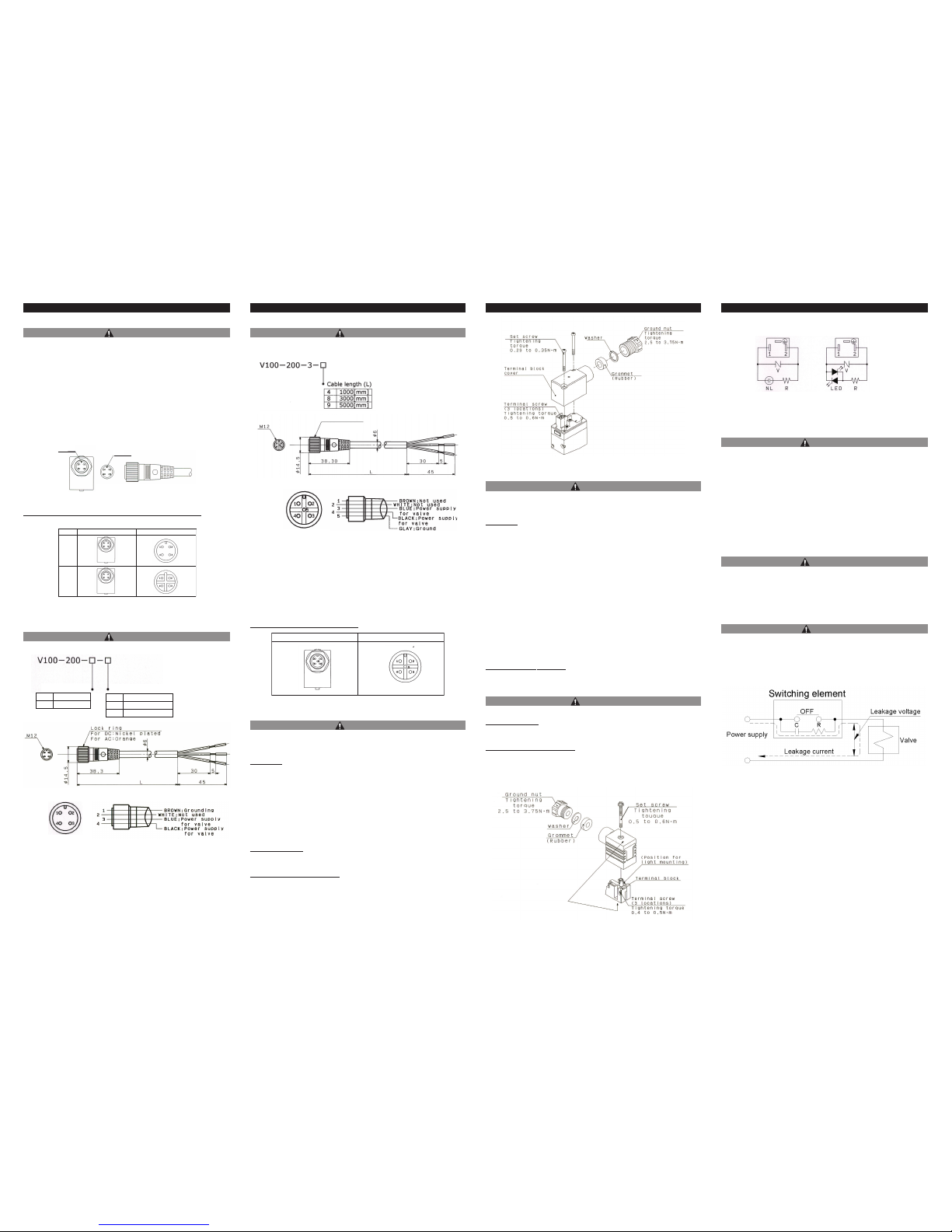
3.4 M12 connector
CAUTION
1. M12 connector types have an IP65 (enclosure) rating, offering
protection from dust and water. However please note: these products
are not intended for use in water.
2. Do not use a tool to mount the connector, as this may cause damage.
Only tighten by hand. (0.4 to 0.6 N?m)
3. Excessive stress on the cable connector will violate the IP65 rating.
Please use caution and do not apply a stress of 30 N or greater.
Failure to meet IP65 performance may result if using alternative
connectors than those shown below, or when insufficiently tightened.
Note) When connecting the female M12 connector (4 and 5 pin type) to the
male connector, please be aware of the position of the keyway.
Forcing the female connector onto the male when the keyway is not
positioned correctly can damage the pins.
Enlarged view of connector keyway (In case of 4pins type)
SGH100-TFM86
3.5 Connector with cable.
CAUTION
• For W type (4pins connector)
3 Installation (continued)
3.6 Connector with cable.
CAUTION
• For V type (5pins connector)
*Only as for the DC type.
Enlarged view of connector keyway
3.7 How to use Conduit terminal
CAUTION
Conduit terminal types have an IP65 (enclosure) rating, offering protection
from dust and water. However please note: these products are not intended
for use in water.
Connection
1) Loosen the holding screws and remove the cover from the terminal
block.
2) Loosen the screws in the terminal block. Insert the lead core wires or
crimped terminals to the terminals, and secure the wires by retightening
the terminal screw.
3) Secure the cored wires by fastening the ground nut.
When making connections, take note that using other than the
supported size (ø4.5 to ø7) heavy duty cord will not satisfy IP65
(enclosure) standards. Also, be sure to tighten the ground nut and
holding screw within their specified torque ranges.
Compatible cable
Cord O.D.: ø4.5 to ø7
(Reference) 0.5 to 1.5mm2, 2-core or 3-core, equivalent to JIS C3306
Applicable crimped terminals
O-terminals : Equivalent to R1.25 -3 defined in the JIS C2805
Y- terminals :Equivalent to 1.25 -3 manufactured by J.S.T Mfg. Co., Ltd.
3 Installation (continued)
3.8 How to use DIN terminal
CAUTION
DIN terminal types have an IP65 (enclosure) rating, offering protection from
dust and water.However please note: these products are not intended for use
in water.
Connection
1) Loosen the holding screw and pull the connector out of the solenoid
valve terminal block.
2) After removing the holding screw, insert a flat head screwdriver or
similar tool, into the notch on the bottom of the terminal block and pry it
open, separating the terminal block and the housing.
3) Loosen the screw (slotted screws) in the terminal block. Insert the lead
core wires or crimped terminal to the terminals according to the
connection method, and secure the wires by re-tightening the terminal
screw.
4) Secure the cord by fastening the ground nut.
When making connections, take note that using other than the supported size
(ø4.5 to ø7) heavy duty cored will not satisfy IP65 (enclosure) standards.
Also, be sure to tighten the ground nut and holding screw within their
specified torque ranges.
Changing the entr
y direction
After separating the terminal block and housing, the cord entry can be
changed by attaching the housing in the opposite direction 180°.
*Be careful not to damage the element, etc. with the cord’s lead wires.
CAUTION
Plug in and pull out the connector vertically without tilting to one side.
Compatible cable
Cord O.D.: ø4.5 to ø7
(Reference) 0.5 to 1.5mm
2
, 2-core or 3-core, equivalent to JIS C3306
Applicable crimped terminals
O-terminals : Equivalent to R1.25 -4M defined in the JIS C2805
Y- terminals :Equivalent to 1.25 -3L manufactured by J.S.T Mfg. Co., Ltd.
Bar-terminals : up to size 1.5
3.8 How to use DIN terminal
CAUTION
2. Leakage voltage.
Take note;that current may leak through the resistor, C-R element, etc.,
particularly when a resistor is set up in parallel with the switching
element and when a C-R element (surge voltage suppressor) is used
to protect the switching element. This creates the possible danger that
the valve will not turn off.
With AC coil : 8% or less of rated voltage.
With DC coil : 3% or less of rated voltage.
3. Low temperature operation.
1) The minimum temperature that this valve can be used at is -5°C.
Take appropriate measures to avoid freezing of drainage, moisture,
etc. in the pilot airline by using an air dryer.
2) When using valves for water application in cold climates, take
appropriate countermeasures to prevent the freezing in tubing after
cutting the water supply from the pump, e.g. drain the water. When
heating by steam, be careful not to expose the pilot valve portion to
steam. Installation of a dryer in the pilot airline, and retaining heat in
the body are recommended to prevent freezing in conditions where
the dew-point temperature is high and ambient temperature is low.
4. Operating fluids.
1) Type of operating fluids.
Select model according to the operating fluid for its material.
Please contact SMC for further information.
3 Installation (continued)
3.9 Circuit Diagram with Light/Surge Voltage suppressor
3.10 Precautions on Design
WARNING
1. Cannot be use as an emergency shut-off valve.
The valves presented in this catalog are not designed for safety
applications such as an emergency shutoff valve.If the valves are used
in this type of system, other positive measures for safety should be also
adopted in conjunction.
2. Solenoid valves are not suitable for use as explosion proof valves.
3. Maintenance space.
The installation should have sufficient space for maintenance activities.
( removal of valve, etc.)
4. Liquid rings
In cases with a flowing liquid, provide a by-pass valve in the system to
prevent the liquid from entering the liquid seal circuit.
3.11 Selection
WARNING
1. Confirm the specifications.
Do not operate at pressures or temperatures, etc. beyond the range of
specifications, as this can cause damage or malfunction. (Refer to
specifications in catalog.)
Keyway
Keyway
M12 connector Connector with cable
DC
type
AC
type
Specificatio
Cable length (L)
1 For DC
2 For AC
4 1000 [mm]
8 3000 [mm]
9 5000 [mm]
Cable colors
Cable cover colors for core wire
Socket pin
connector
pin assignment
Terminal
Lock rin
g
M12 connector Connector with cable
NL : Neon Lamp, R : Resister LED : Light Emitting diode, R : Resister
V : Varistor V : Varistor
AC circuit diagram
DC circuit diagram
Socket pin
connector
pin assignment
(Rating symbol)
Refer to the table of DIN
Connector
p
art No. below.
Figure 4.
Table 5.
Figure 5.
Figure 6.
Table 6.
Figure 7.
Figure 8.
Figure 9.
Figure 10.
 Loading...