

SMC Networks S070 Series Installation And Maintenance Manual
2 INTENDED CONDITIONS OF USE
2.1 Specifications
Note 1) Use dry air and prevent condensation at low temperatures.
Note 2) Vibration resistance: No malfunction resulted in 45 to 2000 Hz, a one-sweep test
performed in the axial and right angle directions of the main valve and armature
for both energized and de-energized states.
Impact resistance: No malfunction resulted in a impact test using a drop impact
tester. The test was performed one time each in the axial and right angle
directions of the main valve and armature, for both energized and de-energized
states.
With the 0.1 W specification, the vibration and impact resistance is 10/50 m/s
2
or less.
Note 3) With the low vacuum specification, the operating pressure range is 1.33 x 10
2
Pa to the maximum operating pressure.
Note 4) The maximum operating pressure is limited, with reference to allowed
combinations Power consumption - Pressure specifications - Flow rate. Refer to
the following paragraphs for details.
2.2 Solenoid specifications
Note 1) With a light/surge voltage suppressor and power saving circuit, the light
comsumes a power equivalent to 2 mA.
Note 2) With a power saving circuit, keep the voltage fluctuation within 24 VDC ± 5%.
2.3 Power consumption - Pressure specifications Flow rate
Note) An option only applicable to 24 VDC plug lead type.
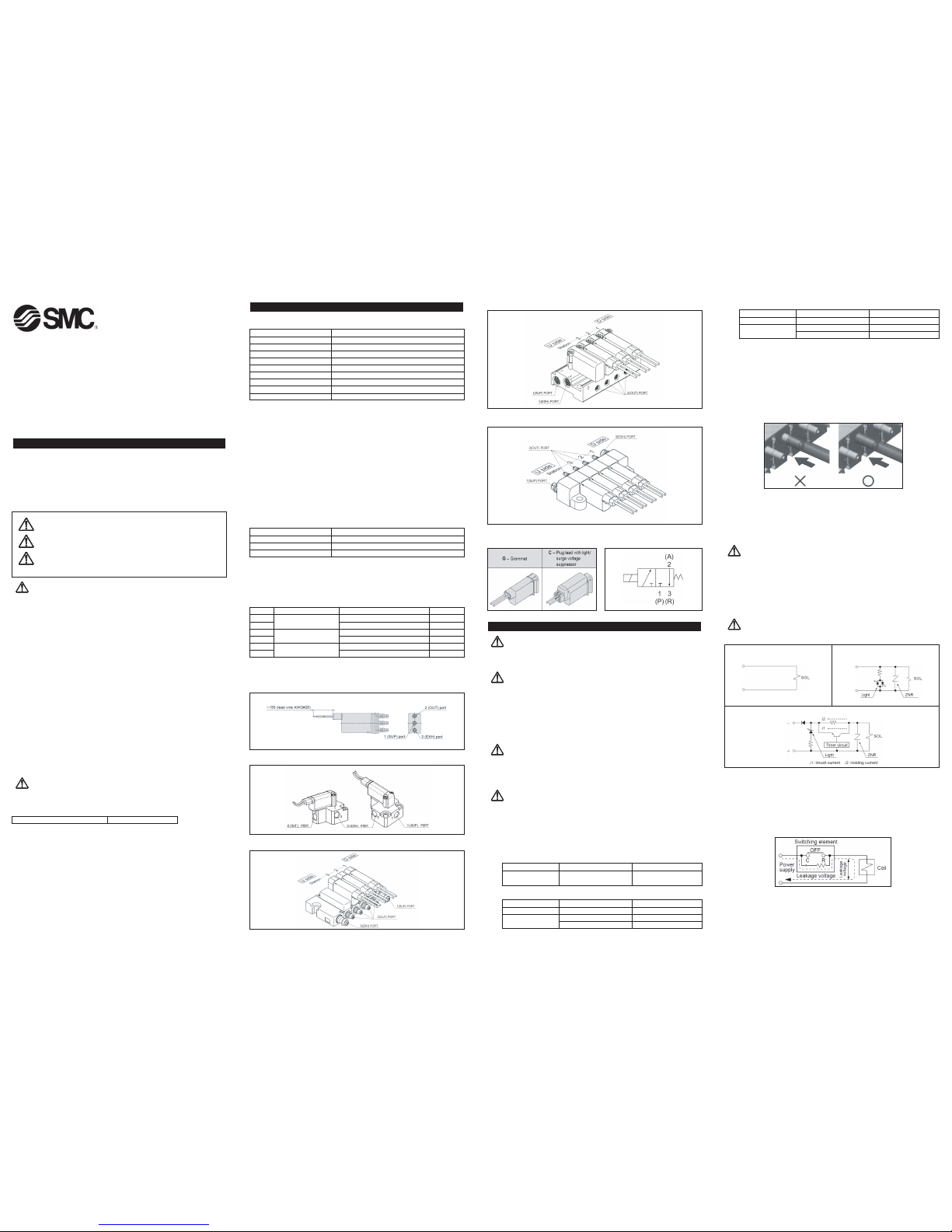
2.4 Piping
Body ported
Base mounted with screws
Base mounted manifold, stacking base type
Read this manual before using this product.
The information within this document is to be used by pneumatically trained
personnel only.
For future reference, please keep manual in a safe place.
This manual should be read in conjunction with the current catalogue.
1 SAFETY
1.1 General recommendation
These safety instructions are intended to prevent a hazardous situation and/or
equipment damage. These instructions indicate the level of potential hazard by label of
"Caution", "Warning" or "Danger". To ensure safety, be sure to observe ISO4414
(Note1), JIS B 8370 (Note2) and other safety practices.
Note 1:ISO 4414:Pneumatic fluid power - General rules relating to systems.
Note 2:JIS B 8370:Pneumatic system axiom.
WARNING:
• The compatibility of pneumatic equipment is the responsibility of the person
who designs the pneumatic system or decides its specifications.
Since the products specified here are used in various operating conditions, their
compatibility for the specific pneumatic system must be based on specifications or
after analysis and/or tests to meet your specific requirements.
• Only trained personnel should operate pneumatically operated machinery
and equipment.
Compressed air can be dangerous if an operator is unfamiliar with it. Assembly,
handling or repair of pneumatic systems should be performed by trained and
experienced operators.
• Do not service machinery/equipment or attempt to remove components
until safety is confirmed.
Inspection and maintenance of machinery/equipment should only be performed
after confirmation of safe locked-out control positions.
When equipment is to be removed, confirm the safety process as mentioned
above. Switch off air and electrical supplies and exhaust all residual compressed
air in the system.
Before machinery/equipment is re-started, ensure all safety measures to prevent
sudden movement of cylinders etc. (Bleed air into the system gradually to create
backpressure, i.e. incorporate a soft-start valve).
• Contact SMC if the product is to be used in any of the following conditions:
Conditions and environments beyond the given specifications, or if product is used
outdoors.
Installations on equipment in conjunction with atomic energy, railway, air
navigation, vehicles, medical equipment, food and beverage, recreation
equipment, emergency stop circuits, press applications, or safety equipment.
An application, which has the possibility of having negative effects on people,
property, or animals, requiring special safety analysis.
CAUTION:
Ensure that the air supply system is filtered to 5 micron.
1.2 Conformity to standard
This product is certified to and complies with the following standards:
Base mounted manifold, bar base type
Body ported manifold, stacking type
2.5 Electrical entry 2.6 Circuit Symbols
3 INSTALLATION
WARNING:
Do not install unless the safety instructions have been read and understood.
3.1 Environment
WARNING:
Do not use in an environment where the product is directly exposed to corrosive
gases, chemicals, salt water, water or steam.
Do not use in an explosive atmosphere.
The product should not be exposed to prolonged sunlight. Use a protective cover.
Do not mount the product in a location where it is subject to strong vibrations
and/or shock. Check the product specifications for above ratings.
Do not mount the product in a location where it is exposed to radiant heat.
3.2 Piping
CAUTION:
Before piping make sure to clean up chips, cutting oil, dust etc.
When installing piping or fitting into a port, ensure that sealant material does not
enter the port inside. When using seal tape, leave 1.5 to 2 threads exposed on the
end of pipe/fitting.
CAUTION:
Screwing in M5/M3 thread
Tighten M3 screws 1/4 turn past hand tightness, and M5 screws by 1/6 turn past
hand tightness (1/4 turn for miniature fittings). Over tightening the screws may
cause bending of the screws or deformation of the gasket, resulting in air leaks.
Loose, under tightened screws may also result in air leaks.
Applicable tubing size
Body ported type, barb fitting
Base mounted, stacking type, barb fitting
Installation and Maintenance Manual
Series S070
Compact Direct Operated 3 Port solenoid valve
CAUTION: Operator error could result in injury or equipment damage.
WARNING: Operator error could result in serious injury or loss of life.
DANGER: In extreme conditions, there is a possible result of serious
injury or loss of life.
Body ported mounted, stacking type, barb fitting
Note: If other manufacturers' fittings are used with the base-mounted bar manifold,
please follow the appropriate fitting specifications.
Tube fitting
Cut the required length of tube at right angles to the tube axis (use tube cutter TK-
1, 2,3). Allow sufficient excess length.
Fit the tube up to the far end of the barb. If the tube is not completely fitted over
the barb, air leaks may result, and the tube could become detached.
When fitting the tube onto the barb fitting, insert it up to the end of the barb in a
direction parallel to the tube axis, to avoid placing excessive lateral force on the
barb fitting.
When removing a tube from a barb fitting, take care not to exert excessive lateral
force on the barb fitting. If a cutter is used to remove a tube, take care not to
damage the barb fitting.
After fitting, the tubes should not be subject to excessive loads caused by pulling,
compressing or bending.
3.3 Electrical connection
CAUTION:
When DC power is connected to a solenoid valve equipped with light and/or surge
voltage suppressor, check for polarity indications.
For polarity indications:
No diode to protect polarity: if polarity connection is wrong, the diode in the
valve or switching device at control equipment or power supply may be
damaged.
With diode to protect polarity: if polarity connection is wrong, the valve does not
switch.
CAUTION:
Internal wiring
Electrical circuit
Use electric circuits that do not produce any contact chattering.
The voltage should be within 10% of the rated voltage. If the rated voltage is less
than 6 V DC and response is an important factor, voltage drops should be taken into
consideration.
When a C-R component (surge voltage protector) is used to protect the switching
element, be aware that the leakage voltage is increased because of the leakage
current flowing through the C-R components. Limit the residual leakage voltage to
2% or less of the rated voltage.
Make sure that the correct voltage is applied, to avoid malfunction or coil burnout.
Arrange the lead wires so that excessive force is not exerted on them. This will
avoid coil rupture.
S070-TFI31GB
Page 1 of 2
X
Valve construction Poppet
Fluid Air/Inert gas/Low vacuum (1.33 x 10² Pa)
Maximum operating pressure 0.3 MPa (0.35 W, 0.1 W), 0.5 MPa (0.5 W)
Proof pressure 1 MPa
Ambient and fluid temperature
Note1)
-10 to 50°C
Lubrication Not required
Impact/Vibration resistance
Note2)
30/150 m/s
2
Enclosure IP40
Weight 5 g (single unit valve)
Mounting orientation Free
EMC (Electro Magnetic Compatibility) EN 61000-6-2, EN 55011
Power consumption
Note1)
0.35 W (standard), 0.5 W (high voltage), 0.1 W (holding)
Rated coil voltage 3, 5, 6, 12, 24 VDC
Allowable voltage fluctuation
Note2)
±10% of the rated voltage
Coil insulation type Equivalent to class B
Port Applicable tube Recommended tube
1(SUP), 2(OUT),
ø3.18/ ø2 TIUB01
3 (EXH)
Port Applicable Tube Recommended Tube
1(SUP), 3(EXH) ø6/ ø4 TS0604/TU0604
2(OUT)
ø4/ ø2.5 TS0425/TU0425
ø3.18/ ø2 TIUB01
Symbol Power consumption (W) Maximum operating pressure (MPa) Cv factor
A 0.1 0.021
B 0.3 0.011
C 0.3 0.021
D 0.5 0.011
E
Note)
0.1 0.011
F
Note)
0.3 0.006
0.5
0.35
(with power saving circuit)
Grommet
(This solenoid valve has no polarity.)
With light/surge voltage suppressor
(This solenoid valve has no polarity.)
With 0.1 W power saving circuit
0.1
Port Applicable Tube Recommended Tube
1(SUP), 3(EXH) ø6/ ø4 TS0604/TU0604
2(OUT)
ø4/ ø2.5 TS0425/TU0425
ø3.18/ ø2 TIUB01
Electrical entries
Refer to section 2 of this manual.
CAUTION:
Power saving circuit of 0.1 W DC (at holding)
Keep the vibration and impact within 10/50 m/s
2
.
Keep the voltage fluctuations within 24 VDC ± 5%.
The power comsumption is 0.35 W DC at inrush (20 ms) and 0.1 W DC at holding.
3.4 Mounting/Removal
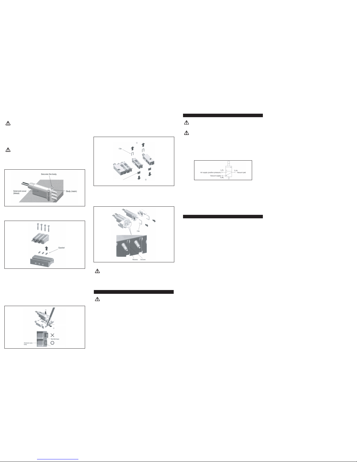
CAUTION:
Body-ported, single unit
To fix a body-ported single-unit solenoid valve, fix the valve body as shown in the
diagram below and tighten the special screws (AXT632-106A-2) to the correct torque
(0.05 to 0.07 Nm). Do not apply excessive force to the coil, or when fitting the
tubes, as this could cause damage. Care should also be taken not to apply excessive
force to the coil section of base-mounted solenoid valves.
Base mounted with screws
For this type, ensure that a gasket is fitted between the valve and the manifold, and
tighten the special mounting screws (AXT632-106A-1) securely to the correct torque
(0.10 to 0.14 Nm).
Base mounted with clips
To install, insert a small flat-blade tip screwdriver into the hole in the mounting
bracket, pull it out by approximately 1 mm (in the direction (1) shown in the
diagram), and install the solenoid valve from above (2), so that it is mounted on the
interface. When the base of the solenoid valve meets the upper surface of the
manifold, press down the body of the solenoid valve and remove the screwdriver
from the mounting bracket. Ensure that a valve body interface gasket is installed.
An internal leaf spring returns the mounting bracket to its original position. Check
that the end surface of the mounting bracket is now flush with the side of the
manifold block (refer to the diagram below).
Similarly, to remove the valve, pull out the mounting bracket and lift the valve
directly upwards. When installing or removing, be careful not to exert excessive
force on the lead wires.
Extending or Shortening Procedures
Base-mounted, stacking type.
(1) Remove the clip and the metal joint of the parts to be extended in the
direction of the arrows (1) and (2), as shown in the diagram.
(2) Add an expansion manifold block assembly, and attach the metal joint and
clip in reverse order to their removal. The clips should be securely inserted so
that they do not protrude from the top surface of the block, and the metal joints
should not protrude from the bottom surface. The clips are used to fix both the
manifold block and the fitting.
Body-ported type
(1) Remove the clips from the parts to be extended, in the direction of the arrow
shown in the diagram. (Insert a flat-blade tip screwdriver into the recess shown
in the lower diagram.)
(2) Add an expansion solenoid valve to the separated parts, and insert the clips
in reverse order to their removal. Insert each clip securely until it reaches the
stopper on the side of the body.
3.5 Lubrication
CAUTION:
SMC products have been lubricated for life at manufacturer, and do not require
lubrication in service.
If a lubricant is used in the system, use turbine oil Class 1(no additive), ISO VG32.
Once lubricant is used in the system, lubrication must be continued because the
original lubricant applied during manufacturing will be washed away.
4 MAINTENANCE
WARNING:
Not following proper procedures could cause the product to malfunction and could
lead to damage to the equipment or machine.
If handled improperly, compressed air can be dangerous. Qualified personnel
should perform assembly, handling and repair of pneumatic system only.
Drain: remove condensate from the filter bowl on a regular basis.
Shut-down before maintenance: before attempting any kind of maintenance make
sure the supply pressure is shut off and all residual air pressure is released from
the system to be worked on.
Start-up after maintenance: apply operating pressure and power to the equipment
and check for proper operation and possible air leaks. If operation is abnormal,
please verify product set-up parameters.
Do not make any modification to the product
Do not disassemble the product, unless required by installation or maintenance
instructions.
Page 2 of 2
S070-TFI31GB
5 LIMITATIONS OF USE
WARNING:
Do not exceed any of the specifications laid out in section 2 of this document or
the specific product catalogue.
CAUTION:
5.1 Vacuum Applications
A normally close (N.C.) valve pressurized at 1(SUP) port can be used within the
maximum operating pressure difference specified for the product. For the applications
below, consideration should be given to the port used, the maximum operating pressure
difference, and the permissible leakage.
For vacuum break use
As shown in the diagram, use 3(R) port for vacuum, and 1(P) port for vacuum
break. The pressure difference between 3(R) and 1(P) is the maximum working
pressure difference for the respective type.
For vacuum-maintaining use
Please consult SMC if limited leakage is allowed, such as to maintain vacuum in a
pressure vessel or similar applications, even within the low vacuum range (1.33 x
10
2
Pa and above).
5.2 Spare parts
Refer to standard S070 catalogue.
5.3 Removal of valves and extending/
shortening of manifolds.
Refer to section 3 of this manual.
6 EUROPEAN CONTACT LIST
6.1 SMC Corporation
Country Telephone Country Telephone
Austria (43) 2262-62 280 Italy (39) 02-92711
Belgium (32) 3-355 1464 Netherlands (31) 20-531 8888
Czech Republic (420) 5-414 24611 Norway (47) 67 12 90 20
Denmark (45) 70 25 29 00 Poland (48) 22-548 50 85
Finland (358) 9-859 580 Portugal (351) 22 610 89 22
France (33) 1-64 76 1000 Spain (34) 945-18 4100
Germany (49) 6103 4020 Sweden (46) 8-603 0700
Greece (30) 1- 342 6076 Switzerland (41) 52-396 3131
Hungary (36) 1-371 1343 Turkey (90) 212 221 1512
Ireland (353) 1-403 9000 United Kingdom (44) 1908-56 3888
6.2 Websites
SMC Corporation www.smcworld.com
SMC Europe www.smceu.com
Metal clip
Metal clip
Metal link
Mounting bracket
Mounting bracket
Metal joint
 Loading...