

SMC Networks S0700 Installation And Maintenance Manual
2 INTENDED CONDITIONS OF USE
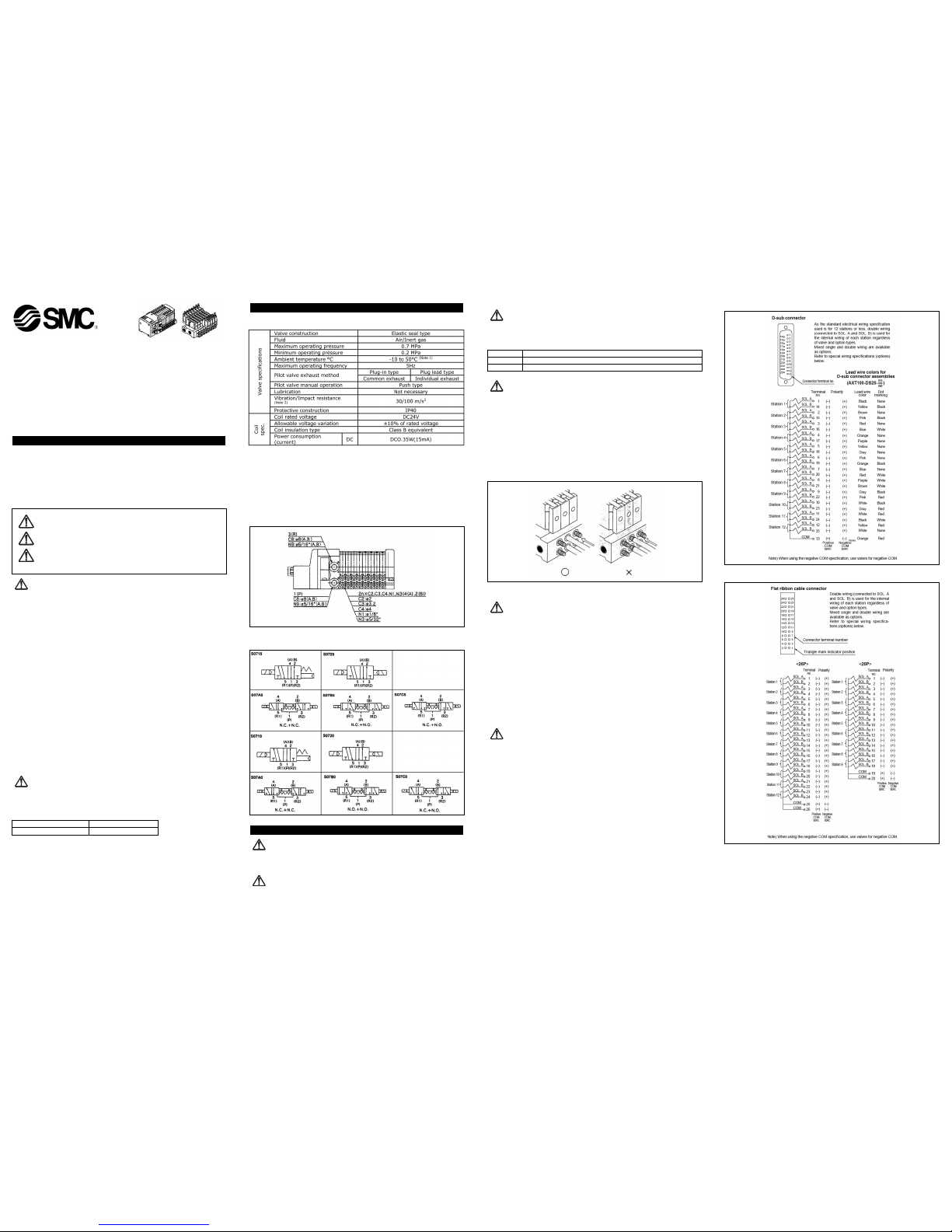
2.1 Specifications
(Note 1) At low temperatures, use dry air with no condensation.
(Note 2) Vibration resistance: Conditions when tested with one sweep of 8.3 to
2000Hz in the axial direction and at a right angle
to the armature, in both energized and
de-energized states
Impact resistance: Conditions when tested with a drop tester in the axial
direction and at a right angle to the armature, one
time each in energized and de-energized states
2.2 Piping
2.3 Circuit Symbols
3 INSTALLATION
WARNING:
Do not install unless the safety instructions have been read and understood.
3.1 Environment
WARNING:
Do not use in an environment where the product is directly exposed to corrosive
gases, chemicals, salt water, water or steam.
Do not use in an explosive atmosphere.
The product should not be exposed to prolonged sunlight. Use a protective cover.
Do not mount the product in a location where it is subject to strong vibrations
and/or shock. Check the product specifications for above ratings.
Do not mount the product in a location where it is exposed to radiant heat.
Read this manual before using this product
The information within this document is to be used by pneumatically trained
personnel only.
For future reference, please keep manual in a safe place.
This manual should be read in conjunction with the current catalogue.
1 SAFETY RECOMMENDATION
1.1 General recommendation
These safety instructions are intended to prevent a hazardous situation and/or
equipment damage. These instructions indicate the level of potential hazard by label of
"Caution", "Warning" or "Danger". To ensure safety, be sure to observe ISO4414
(Note1)
,
JIS B 8370
(Note2)
and other safety practices.
Note 1:ISO 4414:Pneumatic fluid power - General rules relating to systems.
Note 2:JIS B 8370:Pneumatic system axiom.
WARNING:
• The compatibility of pneumatic equipment is the responsibility of the person
who designs the pneumatic system or decides its specifications.
Since the products specified here are used in various operating conditions, their
compatibility for the specific pneumatic system must be based on specifications or
after analysis and/or tests to meet your specific requirements.
• Only trained personnel should operate pneumatically operated machinery
and equipment.
Compressed air can be dangerous if an operator is unfamiliar with it. Assembly,
handling or repair of pneumatic systems should be performed by trained and
experienced operators.
• Do not service machinery/equipment or attempt to remove components until
safety is confirmed.
Inspection and maintenance of machinery/equipment should only be performed
after confirmation of safe locked-out control positions.
When equipment is to be removed, confirm the safety process as mentioned above.
Switch off air and electrical supplies and exhaust all residual compressed air in the
system.
Before machinery/equipment is re-started, ensure all safety measures to prevent
sudden movement of cylinders etc. (Bleed air into the system gradually to create
backpressure, i.e. incorporate a soft-start valve).
• Contact SMC if the product is to be used in any of the following conditions:
Conditions and environments beyond the given specifications, or if product is used
outdoors.
Installations on equipment in conjunction with atomic energy, railway, air
navigation, vehicles, medical equipment, food and beverage, recreation
equipment, emergency stop circuits, press applications, or safety equipment.
An application, which has the possibility of having negative effects on people,
property, or animals, requiring special safety analysis.
CAUTION:
Ensure that the air supply system is filtered to 5 micron.
1.2 Conformity to standard
This product is certified to and complies with the following standards:
3.2 Piping
CAUTION:
Before piping make sure to clean up chips, cutting oil, dust etc.
When installing piping or fitting into a port, ensure that sealant material does not
enter the port inside. When using seal tape, leave 1.5 to 2 threads exposed on the
end of pipe/fitting.
CAUTION:
Tube piping method
(Plug lead/ barb fitting type)
1. Cut the tube to the necessary length at right angles to the axial direction using a
tube cutter TK-1, 2 or 3.
2. Insert the tube up to the barb end. If the tube is only pushed in part way, this can
cause air leakage or cause the tube to come out.
3. When inserting the tube into to the barb fitting, insert parallel to the axial direction
to avoid placing excessive lateral load on the barb fitting.
4. Care should also be taken to avoid placing excessive lateral load on the barb fitting
when removing the tube from the barb fitting. When removing using a cutter, care
should also be taken to avoid scratching the barb fitting.
5. After completing tube piping, avoid excessive loads that could pull, compress or
bend the tube.
3.3 Electrical connection
CAUTION:
When DC power is connected to a solenoid valve equipped with light and/or surge
voltage suppressor, check for polarity indications.
For polarity indications:
No diode to protect polarity: if polarity connection is wrong, the diode in the
valve or switching device at control equipment or power supply may be
damaged.
With diode to protect polarity: if polarity connection is wrong, the valve does
not switch.
Cable safety instructions
Avoid mis-wiring, as this can cause malfunction, damage and fire in the unit.
To prevent noise and surge in signal lines, keep all wiring separate from power
lines and high voltage lines. Otherwise, this can cause a malfunction.
Check wiring insulation, as defective insulation can cause damage to the unit when
excessive voltage or current is applied.
Do not bend or pull cables repeatedly, and do not place heavy objects on them or
allow them to be pinched. This can cause broken
CAUTION:
Surge voltage circulation
Surge voltage generated when the power is cut off can flow to the load device in
non-electrified state through the output circuit etc. In particular in a load device in
electrified state, if a load device with high capacity (power consumption) is connected
so that it shares the supply power, this can cause malfunction of the solenoid valve or
damage to the circuit elements inside the solenoid valve or elements in the output
device. A surge absorbing diode should therefore be installed in the COM line of the
load device.
CAUTION: Operator error could result in injury or equipment damage.
WARNING: Operator error could result in serious injury or loss of life.
DANGER: In extreme conditions, there is a possible result of serious
injury or loss of life.
Electrical Wiring D-sub connector
Flat cable connector
S0700-TFJ34GB
Installation and Maintenance Manual
S0700 5 Port Solenoid Valve
EMC directive 89/336/EEC EN 61000-6-2
EN 55011
X
Thread Appropriate tightening torque (Nm)
M3 By hand + ¼ turn with the wrench
M5 By hand + 1/6 turn with the wrench (1/4 turn for miniature fittings)
Terminal box kit Lead wire cable kit
CAUTION:
Internal wiring specifications
With light/surge voltage suppressor circuit.
No polarization as the light has non-polar specification.
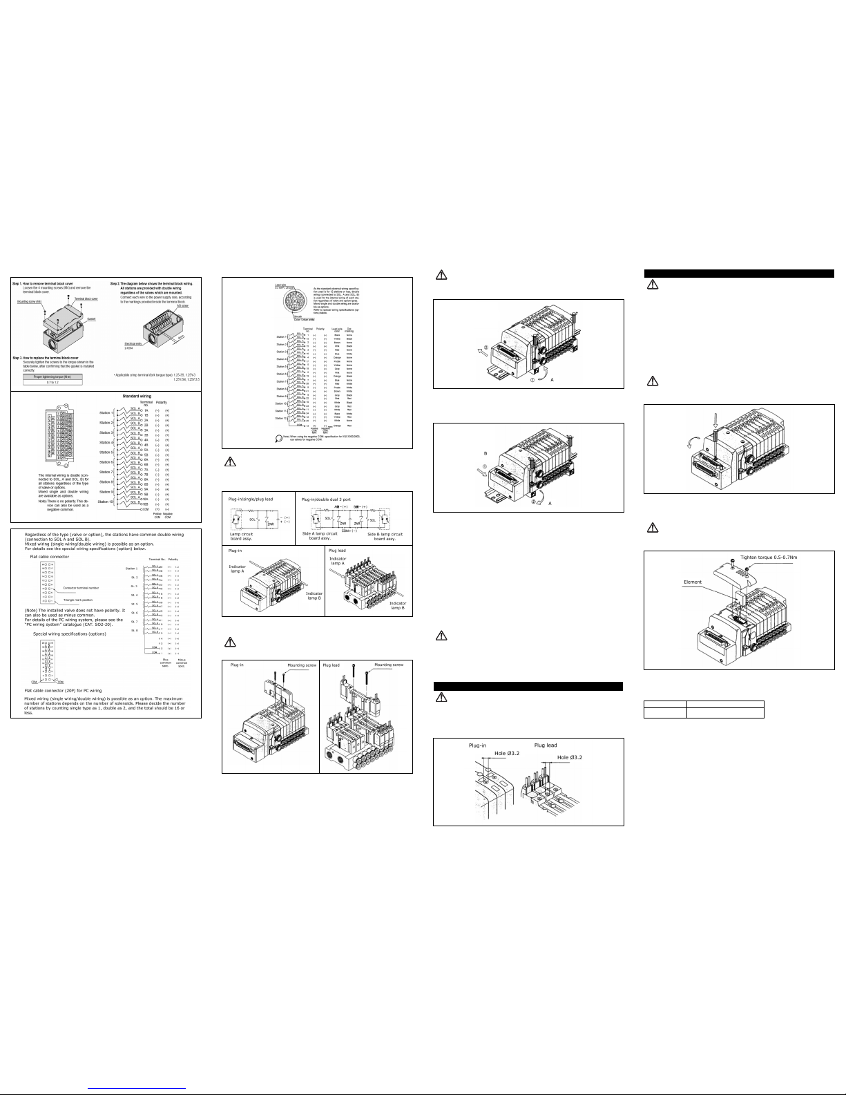
3.4 Mounting
CAUTION:
Valve mounting method
Tighten to a torque of 0.017-0.23 Nm to clamp the gasket securely.
CAUTION:
Mounting onto and removal from DIN rail
Plug-in
Removal procedure
Loosen the clamp screws on the end plates on both sides.
Lift side A of the manifold base and pull out in the direction indicated by 2 in
the diagram.
Mounting procedure
Hook side B of the manifold base on the DIN rail.
Push in side A and mount onto the DIN rail, then tighten the clamp screws on side
A of the end plate. The correct tightening torque is 0.4-0.6 Nm.
Plug lead
Removal procedure
Loosen the clamp screws on the end plates on both sides.
Lift side A of the manifold base and pull out in the direction indicated by 2 in
the diagram.
Mounting procedure
Hook side B of the manifold base on the DIN rail.
Push in side A and mount onto the DIN rail, then tighten the clamp screws on side
A of the end plate. The correct tightening torque is 0.4-0.6 Nm.
3.5 Lubrication
CAUTION:
SMC products have been lubricated for life at manufacture, and do not require
lubrication in service.
If a lubricant is used in the system, use turbine oil Class 1(no additive), ISO VG32.
Once lubricant is used in the system, lubrication must be continued because the
original lubricant applied during manufacturing will be washed away.
4 SETTINGS AND PROGRAMMING
WARNING:
Manual override
The manual override is used for switching the main valve.
Push style (tools needed)
Push down the manual override button with a small screwdriver until it stops.
5 MAINTENANCE
WARNING:
Not following proper procedures could cause the product to malfunction and could
lead to damage to the equipment or machine.
If handled improperly, compressed air can be dangerous. Assembly, handling and
repair of pneumatic system should be performed by qualified personnel only.
Drain: remove condensate from the filter bowl on a regular basis.
Shut-down before maintenance: before attempting any kind of maintenance make
sure the supply pressure is shut off and all residual air pressure is released from
the system to be worked on.
Start-up after maintenance: apply operating pressure and power to the equipment
and check for proper operation and possible air leaks. If operation is abnormal,
please verify product set-up parameters.
Do not make any modification to the product
Do not disassemble the product, unless required by installation or maintenance
instructions.
CAUTION:
How to change connector entry direction
(Plug-in type only)
The entry direction of the connector can be changed from upwards to sideways just by
pushing the manual override. To change from sideways to upwards, manual override is
not necessary.
CAUTION:
Built-in silencer element
(Plug-in type only)
There is a built-in filter element in the manifold base end plate. If the element is dirty
or blocked, this may cause malfunction such as decreased cylinder speed, so the
element should be replaced regularly.
Element part number
* This product number is for a set of 10 elements.
To replace, remove the cover on top of the element and remove the old element using
a flat bladed screwdriver.
S0700-TFJ34GB
Type Element part number
Built-in silencer SS0700-82A
Direct exhaust (-S)
,
 Loading...