

SMC Networks RS2H Series, RS2H-R63, RS2H-R50, RS2H-R80 Operation Manual
Doc. no. RS2H-OM0012P- B
PRODUCT NAME
HEAVY DUTY STOPPER CYLINDER
MODEL / Series / Product Number
RS2H Series (φ50 to φ80)

Contents
Safety Instructions P.2
1. Specifications P.4
1-1. Cylinder specifications
1-2. Spring force of single acting and double acting with spring
1-3. Standard stroke
1-4. Cylinder mass
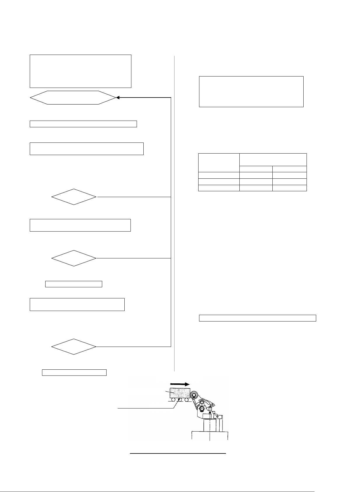
2. Model selection P.5
3. Installation P.8
3-1. Operating air
3-2. Piping
3-3. Operating conditions
3-4. Cautions for mounting
3-5. How to change the relationship between transfer direction and piping position
3-6. How to change piping port position
3-7. Shock absorber resistance adjustment method
4. Operation P.12
5. Pneumatic circuit P.12
6. Maintenance P.13
6-1. Check items
6-2. How to replace shock absorber
6-3. Seal replacement
6-3-1. Disassembly & Reassembly
6-3-2. Seal removal
6-3-3. Grease application
6-3-4. Seal installation
6-4. Consumable parts
6-4-1. Replacement parts
6-4-2. Seal storage
7. Auto Switch P.17
7-1. Applicable auto switch types
7-2. Correct mounting position of auto switch
7-3. How to mount auto switch
7-3-1. D-M9□/D-A9□
7-3-2. D-P3DW□
8. Proximity switch P.20
8-1. Proximity switch specifications / Maker: OMRON Co. Ltd.
8-2. How to mount proximity switch
9. Troubleshooting P.21
10. Construction P.23
-1-
Warning
1. The comp ati bil ity of the product is the resp onsi bil ity of the per so n wh o desi gns th e eq uipm e nt or
4. Contact SMC beforehand and take special consideration of safety measures if the product is to
RS2H
Safety Instructions
These safety instructions are intended to prevent hazardous situations and/or equipment damage.
These instructions indicate the level of potential hazard with the labels of “Caution,” “Warning” or “Danger.”
They are all important notes for safety and must be followed in addition to International Standards
(ISO/IEC)*1) , and other safety regulations.
*1) ISO 4414: Pneumatic flu id pow er -- General rules relating to systems.
ISO 4413: Hydraulic fluid pow er -- General rules relating to systems.
IEC 60204-1: Safety of machinery -- Electrical equipment of machines .(Part 1: General requirements)
ISO 10218-1992: Manipulating industrial robots -Safety.
etc.
Caution
Warning
Danger
Caution indicates a hazard with a low level of risk which, if not avoided, could result
in minor or moderate injury.
Warning indicates a hazard with a medium level of risk which, if not avoided, could
result in death or serious injury.
Danger indicates a hazard with a high level of risk which, if not avoided, will result
in death or serious injury.
decides its specif i cat i ons.
Since the product specified here is used under various operating conditions, its compatibility with specific
equipment must be decided by the person who desig ns the equ ipment or dec ides its spec ifications based o n
necessary analysis and test results.
The expected performance and safety assurance of the equipment will be the responsibility of the person who
has determined its compatibility with the product.
This person should also continuously review all specifications of the product referring to its latest catalog
information, with a view to giving due consideration to any possibility of equipment failure when configuring the
equipment.
2. Only personne l with appropriate training should operate m a chinery and equipme nt .
The product specified here may become unsafe if handled incorrectly.
The assembly, operation and maintenance of machines or equipment including our products must be
performed by an operator who is appropriately trained and experienced.
3. Do not service or attempt to remove product and machinery/equipment until s af e t y is confirmed.
1.The inspection and maintenance of machinery/equipment should only be performed after measures to
prevent falling or runaway of the driven objects have been confirmed.
2.When the product is to be removed, confirm that the safety measures as mentioned above are implemented
and the power from any appropriate source is cut, and read and understand the specific product precautions
of all relevant products carefully.
3. Before machinery/equipment is restarted, take measures to prevent unexpected operation and malfunction.
be used in any of t he f oll owing conditions.
1. Conditions and environments outside of the given specifications, or use outdoors or in a place exposed to
direct sunlight.
2. Installation on equipment in conjunction with atomic energy, railways, air navigation, space, shipping,
vehicles, military, medical treatment, combustion and recreation, or equipment in contact with food and
beverages, emergency stop circuits, clutch and brake circuits in press applications, safety equipment or
other applications unsuitable for the standard specifications described in the product catalog.
3. An application which could have negative effects on people, property, or animals requiring special safety
analysis.
4.Use in an interlock circuit, which requires the provision of double interlock for possible failure by using a
mechanical protective function, and periodical checks to confirm proper operation.
-2-
Caution
or 1.5 years after the product
∗
warranty.
The use of SMC products with production equipment for the manufacture of weapons of mass
or technology from one country to another are govemed by the
security laws and regulation of the countries involved in the transaction. Prior to the
ollowed.
The product is provided for use in manufacturing industries.
RS2H
Safety Instructions
1.The product i s pr ovided for use in manuf ac turing industries.
The product herein descr i bed is basically provided for peaceful us e in manufacturing industries.
If considering using the pr oduct in other i ndustr ies, consu lt SMC before hand a nd exchan ge specif ications
or a contract if necessary.
If anything is unclear, contact your nearest sales branch.
Limited warranty and Disclaimer/Compliance Requirements
The product used is subject to the following “Limited warranty and Disclaimer” and “Compliance
Requirements”.
Read and accept them before using the product.
Limited warran ty and Discla ime r
1.The warranty period of the product is 1 year in service
isdelivered.∗2)
Also, the product may have specified durability, running distance or replacem ent parts. Pleas e
consult your nearest sal es branch.
2. For any failur e or da mage reported withi n t he warranty period whi c h is clearly our responsibility,
a replacement product or necessary part s will be provided.
This limited war r anty applies only t o our pr oduct independentl y, and not to any other dam age
incurred due to the failure of the product.
3. Prior to using SMC products, please read and understand the warranty terms and disclaimers
noted in the speci f ied catalog for the particular products.
2) Vacuum pads are exclude d fr om t hi s 1 year warranty.
A vacuum pad is a consumable part, so it is warranted for a y ear after it is delivered.
Also, even withi n t he warranty peri od, the wear of a product d ue t o t he use of the vacuum
pad or failure due to the deterioration of rubber material are not covered by the limited
Compliance Requirem e nts
1.
destruction(WMD) or any other weapon is strictly prohibited.
2. The exports of SMC products
relevant
shipment of a SMC product to another country, assure that all local rules goveming that export
are known and f
-3-
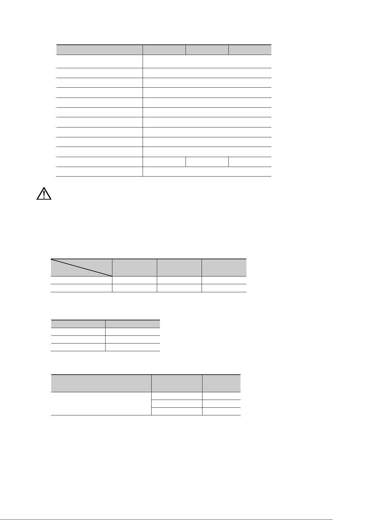
1. Specifications
Bore size
Standard stroke
Ø50
30
Ø63
30
Ø80
40
Double acting with spring
Ø50
1.70
Ø63
2.78
Ø80
4.96
Double acting, Double acting spring,
Single acting spring extended
Extended
40.3
78.5
88.2
Retracted
139.5
174.6
217.3
Bore
1-1. Cylinder specifications
(1) Check the specificat i ons.
1-2. Spring force of single act ing and double act ing with spring (N)
1-3. Standard stroke (mm)
Bore size (mm) Ø50 Ø63 Ø80
Action
Rod end shape Lever with built-in shock absorber
Operating fluid Air
Proof pressure 1.5MPa
Max. operating pressure 1.0MPa
Ambient and fluid temperature
Lubrication Not required (Non-lube)
Cushion Rubber bumper
Stroke length allowance
Mounting Flange
Port size (Rc, NPT, G) 1/8 1/4 1/4
Auto switch Mountable
-10~60℃ (No freezing)
+1.4
0
Warning
This product is designed for use in industrial compressed air systems. Using it at a pressure or
temperature outsi de of the specified range may cause damag e and/ or malfunction.
Please contact y our SMC representative when using fluids other than compressed air made by
pneumatic equipment.
Ø50 Ø63 Ø80
size
1-4. Cylinder mass
Double acting
Single acting (spring retr action)
Action
Bore size
(mm)
- 4 -
Mass
(kg)
2. Model selection
Operating conditions
Determine cylinder bore size temporarily.
Calculate allowable maximum impact load
m
by using conveyor friction coefficient μ.
object, m, at transfer speed v.
Calculate allowable lateral load F at
operating pressure P.
Determine final model.
Operating conditions
4. Coefficient of friction of conveyor: 0.1
Allowable maximum
impact load
μ=0.1
μ=0.2
Ø50
400
280
Ø63
530
365
Ø80
800
565
RS2H50 is determined as the selected model
NO
NO
NO
Transfer speed v [m/min]
FA=mA×μ×g (N)
The flow chart below shows the general procedure to select the optimum model in the RS2H series to suit
the operating requirements.
1. Mass of transferred object: mA
2. Transfer speed: v (m/min)
3. Operating pressure: P (MPa)
4. Coefficient of friction of conveyor: μ
Input operating requirement s.
↓
↓
max
Refer to Table 1
* m
max allowable im pact depends on
conveyor friction coefficient.
(kg)
Model selection example
1. Mass of transferred object: 200 (kg)
2. Transfer speed: 20 (m/min)
3. Operating pressure: 0.5 (MPa)
↓
Cylinder bore size is determined as Ø50 temporarily.
↓
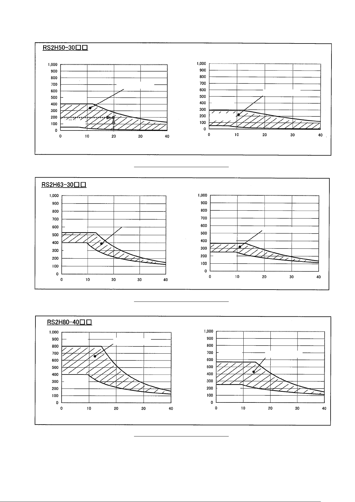
Table 1. RS2H Allowable maximum impact load m
max
(kg)
Bore size
↓
Calculate allowable mass of transferred
Calculate lateral load F
mA≦mmax
↓ YES
↓ For allowable range of m, refer to Figure-1-* (P6).
mA≦m
↓ YES
A
↓
(g: gravitational acceleration
: 9.8m/s
2
)
Confirmation of m
: 200<400 (μ=0.1)
max
↓
m=278(kg) at v=20(m/min) is found on Figure-1-1.
200<278
↓
Lateral load: FA =m
×μ×g
A
=200×0.1×9.8
=196(N)
↓
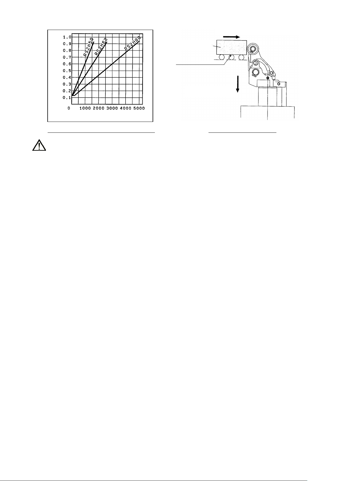
F=776(N) at P=0.5(MPa) is found on Figure-2-1.
196<776
↓
For relationship between lateral load F and operating
pressure P, refer to Figure-2-1 (P7).
↓
FA≦F
↓ YES
Mass of transferred object m [kg]
Coefficient of friction μ
Figure-1. Impact of transferred object
- 5 -
Transfer speed v [m/min]
Transfer speed v [m/min]
Mass of transferred object m [kg]
Operating range
Lower limit
Transfer speed v [m/min]
Transfer speed v [m/min]
Operating range
Operating range
Lower limit
Upper limit
Lower limit
Operating range
Operating range
Transfer speed v [m/min]
Mass of transferred object m [kg]
Transfer speed v [m/min]
Lower limit
Coefficient of friction μ=0.1 Coefficient of friction μ=0.2
Upper limit
Upper limit
Lower limit
Mass of transferred object m [kg]
Figure-1-1. Operating range (RS2H50)
Coefficient of friction μ=0.1 Coefficient of friction μ=0.2
Upper limit
Mass of transferred object m [kg]
Mass of transferred object m [kg]
Figure-1-2. Operating range (RS2H63)
Coefficient of friction μ=0.1
Upper limit
Coefficient of friction μ=0.2
Upper limit
Lower limit
Mass of transferred object m [kg]
Figure-1-3. Operating range (RS2H80)
Note) The graphs indicate the values at normal temperature. (20 to 25°C)
Operating range
- 6 -
Mass of transferred
P: Cylinder operating pressure [MPa]
Operating pressure: P [MPa]
Lateral load: F [N]
object m[kg]
Coefficient of friction μ
Lateral load F=mgμ[N] (g: gravitational acceleration=9.8[m/s2]
Figure-2-1. Lateral load and operating pressure
Figure-2-2. Cylinder extended
Warning
(1) Precautions for model selection
The compatibility of the product is the responsibility of the person who designs the pneumatic
equipment or decides its specifications.
(2) Use within the specified range
If the condition exceeds the specified operating range, it will cause excessive impact or vibration to
the stopper cylinder, leading to possible damages.
(3) There is a possibi lity of dangerous sudden action by air cy linders if sliding par ts of
machinery are twisted d ue t o external forces, etc.
In such cases, human injur y may occur; e.g., by catching hands or feet in the machinery, or
damage to the machinery itself may occur.
Therefore, the machine s hould be designed to avoid such dangers.
(4) A protective cover is recommended to minimize the r i sk of personal injury.
If a stationary object an d mov i ng parts of a cylinder are in clos e pr oximity, personal injury may
occur. Design the structure to avoid cont act with the human body.
(5) Securely tighten all stationary p arts and connected parts so that they will not become loose.
When a cylinder operates with high frequency or a cylinder is installed where there is a lot of
vibration, ensure that all parts remain secure.
(6) Consider a possi ble loss of power source.
Measures should be taken to protect against human injury and equipment damage in the event
that there is a loss of power t o equip m ent controlled by air pressure, electr ic it y or hydraulics, etc.
(7) Consider emerge ncy stops.
Design so that human injur y and/or damage to machinery and equi pment will not be caused
when machinery is stopped by a safety device under abnormal conditions, a pow er outage
or a manual emergency stop.
(8) Consider the action when operation is restar t ed after an emergency stop or abnormal stop.
Design the machinery so that human injury or equipment damage w i ll not occur upon restart of
operation. When the cy lin der ha s to be r eset at t he starting position, insta ll m anual s afet y equip ment.
(9) When a cyli nder is used in a clamping, s uspending and lifting mechanism
There is a danger of work pieces dropping if there is a decrease of thrust due to a drop in circuit
pressure caused by a power outage, etc. Therefore, safety equipment should be installed to prevent
damage to machinery and / or hum an i njur y.
- 7 -
 Loading...