

Page 1

Primary injection testing system
User’s Guide
Raptor
Reference: KAXVMV02
Published: 9 April 2013
Version: 1
Page 2

Raptor
2
Quality is the core of the business activity of EuroSMC, S.A., aimed at fully satisfying
customer needs and expectations.
LIMITATION OF LIABILITY
EuroSMC, S.A. does not recognise any contractual link derived from the information set
forth in this document, including the product features and technical data. The user is solely
liable for the consequences of applying the product referenced in this document. EuroSMC,
S.A. explicitly declines any liability for accidents or undesired results that could be derived
directly or indirectly from the incorrect or incomplete drafting of this document. The partial
or total reproduction of this document is not permitted without the prior written
authorisation of EuroSMC, S.A., which reserves the right to modify this document and the
products hereof without prior notice.
Page 3

Users Guide
3
LIMITED WARRANTY
This product is guaranteed against material and manufacturing defects of the product
itself for a period of 12 months as from the registration date of the product. If this
registration does not occur after 30 days as from the shipping date, the shipping date will
be considered the start of the warranty period.
Our commitment is limited to the substitution and/or replacement of those materials and
components that are proved to be defective during the warranty period.
This warranty does not cover defects caused by the operator outside the product
specifications established in this Instruction Manual.
EuroSMC, S.A. may not be held liable for any direct or indirect damage accidentally
caused by the product.
TRANSPORT CONDITIONS
This warranty covers transport expenses, exclusively according to the following conditions
and the indicated limitations:
1. If the equipment shows a failure that requires transport to the factory during the period
of TWO MONTHS after the entry into force of the Warranty, the transport expenses will
be covered entirely by EuroSMC S.A.
2. If the equipment shows a failure that requires transport to the factory as from TWO
MONTHS and up to the end of the first year, the equipment will be sent to the factory at
the customer’s cost, and the return transport will be paid for by EuroSMC S.A.
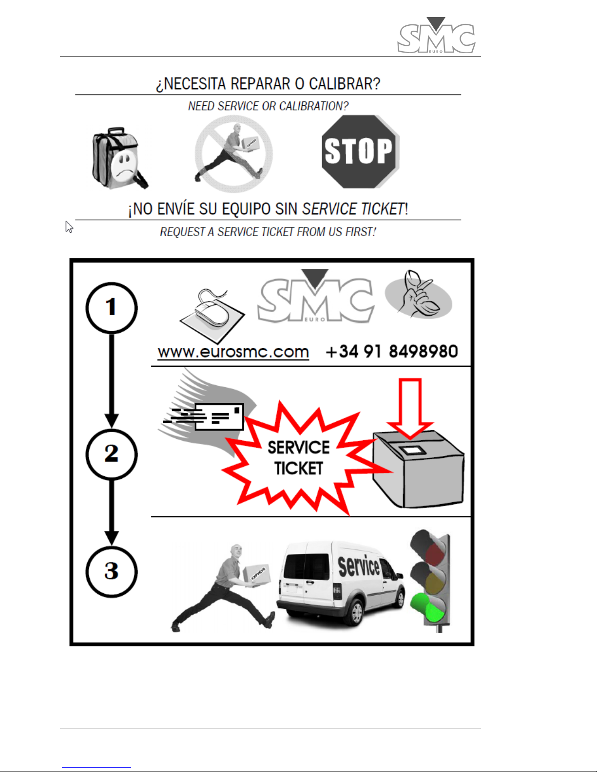
3. The customer may not, in any event, send the equipment to the factory without a
Service Ticket issued by EuroSMC S.A. Otherwise, EuroSMC S.A. will not pay for any cost
referring to transport.
4. If the failure shown by the equipment (after being diagnosed at the factory) is not
covered under the terms of the Warranty, EuroSMC S.A. will not pay for any cost referring
to transport.
HOW TO ACTIVATE THIS WARRANTY
It is essential that you register your product at our web site as soon as possible. This
registration is absolutely necessary so that your warranty enters into force appropriately.
Therefore, visit our web site (www.smcint.com), select the Support option and click on the
Register Product button displayed there. Answer the questions in the Product Registration
questionnaire and click on Send.
If the product is not registered, EuroSMC S.A. reserves the right whether or not to grant
the warranty during the period of one year.
Page 4
Raptor
4
Page 5

Users Guide
5
TABLE OF CONTENTS
LIMITED WARRANTY ............................................................................................................. 3
TRANSPORT CONDITIONS ......................................................................... 3
HOW TO ACTIVATE THIS WARRANTY ........................................................ 3
TABLE OF CONTENTS ........................................................................................................... 5
DECLARATION OF CONFORMITY ........................................................................................ 8
Manufacturer .............................................................................................. 8
Declaration of Conformity ........................................................................... 8
Standards applied ....................................................................................... 8
ELEMENTS COMPRISED IN THE SYSTEM ............................................................................... 9
SAFE USE OF THE EQUIPMENT ........................................................................................... 11
Dangerous Situations ................................................................................ 11
Hazardous situations for the Raptor system .............................................. 12
INTRODUCTION ................................................................................................................. 13
LOCATION OF ELEMENTS .................................................................................................. 14
Raptor-MS (Control panel) ........................................................................ 16
Raptor-MS (Expansion panel) .................................................................... 17
Raptor-SL (Control panel) ......................................................................... 18
Raptor-HH ................................................................................................ 19
HOW TO CONNECT THE SYSTEM ...................................................................................... 20
Positioning of the equipment .................................................................... 20
Make the connections ............................................................................... 21
TURNING ON THE SYSTEM ................................................................................................. 22
AN INITIAL VIEW OF THE CONSOLE ................................................................................... 24
The status LEDs ......................................................................................... 24
Main touch screen .................................................................................... 25
Help and alarms scroll bar ........................................................................... 25
Measurements zone. .................................................................................... 25
Injection zone. ............................................................................................. 28
MAKING THE FIRST CURRENT INJECTION .......................................................................... 30
Steps to follow .......................................................................................... 31
Page 6

Raptor
6
AVAILABLE MEASUREMENTS ............................................................................................... 34
Internal measurements ............................................................................. 34
Hardware measurements ......................................................................... 34
Calculated Measurements ........................................................................ 37
Functions related to measurement ........................................................... 38
OBTAINING THE TEST REPORTS .......................................................................................... 39
Concept of Report and Test....................................................................... 39
How to use the Reports and Tests. ............................................................ 39
Using the RaptorSync programme (for PC with Windows) ........................ 40
Windows XP operating systems ..................................................................... 40
Information and reports of the device. .......................................................... 44
Local database. ........................................................................................... 45
OTHER POSSIBLE INJECTIONS ............................................................................................ 47
ANTICIPATING THE CURRENT THAT WILL BE OBTAINED .................................................... 48
Data entry ................................................................................................. 48
The results of the calculation. ................................................................... 49
MANAGEMENT OF THE PRE-DESIGNED TEMPLATES .......................................................... 51
Template management ............................................................................ 51
Description of Factory templates ............................................................... 52
General ...................................................................................................... 52
Circuit breaker ............................................................................................ 53
Overcurrent relay ........................................................................................ 54
Current Transformer (CT) ............................................................................. 55
Rogowski CT ............................................................................................... 58
Low Power CT ............................................................................................. 60
AC Resistance ............................................................................................. 60
Ground grid ................................................................................................ 62
CT Burden .................................................................................................. 64
Voltage-based CT ....................................................................................... 66
Volt. Transformer (VT) .................................................................................. 68
VT Burden ................................................................................................... 70
Short-circuited PT ........................................................................................ 72
PT ratio ....................................................................................................... 75
SPECIAL FUNCTIONS .......................................................................................................... 78
Recloser. ................................................................................................... 78
CT Magnetisation ...................................................................................... 80
Page 7

Users Guide
7
I NEED MORE CURRENT, VOLTAGE OR POWER ................................................................... 83
Maximum output voltage of the system .................................................... 83
The power supply......................................................................................... 83
Number of turns. ......................................................................................... 84
Number of Raptor-SL units ........................................................................... 84
Minimum load impedance ........................................................................ 84
Distance to burden. ..................................................................................... 84
Parasitic inductance. .................................................................................... 85
CONFIGURATION AND MAINTENANCE ............................................................................ 87
Configuration ............................................................................................ 87
Change language ....................................................................................... 87
Change date and time of the system............................................................. 87
Adjust Internet connection properties (TCP/IP) ............................................... 87
VNC Server ............................................................................................... 88
Keep the system up-to-date ...................................................................... 90
Update control program of the Raptor-HH/M. .............................................. 90
Update firmware of the Raptor-MS unit. ........................................................ 91
Consult the Firmware versions of the Raptor-SL unit. ..................................... 91
Consult serial numbers of the units that make up the system. ......................... 91
Adjust the Hardware meters ......................................................................... 91
PROBLEMS THAT MIGHT ARISE ........................................................................................... 93
SPECIFICATIONS ................................................................................................................ 94
Raptor-MS ................................................................................................. 94
Raptor-SL .................................................................................................. 96
Raptor-HH ................................................................................................ 97
Ordering Information ................................................................................ 98
Page 8

Raptor
8
DECLARATION OF CONFORMITY
For the Raptor system. Applicable to all elements comprised in the system.
Raptor MS / Raptor SL / Raptor HH
Manufacturer
EuroSMC, S.A.
Pol. Industrial P-29 C/Buril, 69
28400 Collado Villalba
Madrid – Spain
Declaration of Conformity
Based on the results of the testing conducted according to adequate standards, the
product complies with the following:
• Directive 2004/108/CE relating to Electromagnetic Compatibility.
• Directive 2006/95/CE relating to Low Voltage.
Standards applied
EN 61010.1 (2010) Safety requirements for electrical equipment for
measurement, control and laboratory use.
EN 50081-1 (1994) Electromagnetic compatibility. Generic emissions standard:
EN 55022 and EN 60555-2.
EN 50082-2 (1996) Electromagnetic compatibility. Generic immunity standard:
IEC 1000-4 -2, -3, -4, -5
Testing has been conducted with a typical configuration. This conformity is indicated by
the CE symbol, which means ‘European Conformity’.
Page 9
Users Guide
9
ELEMENTS COMPRISED IN THE SYSTEM
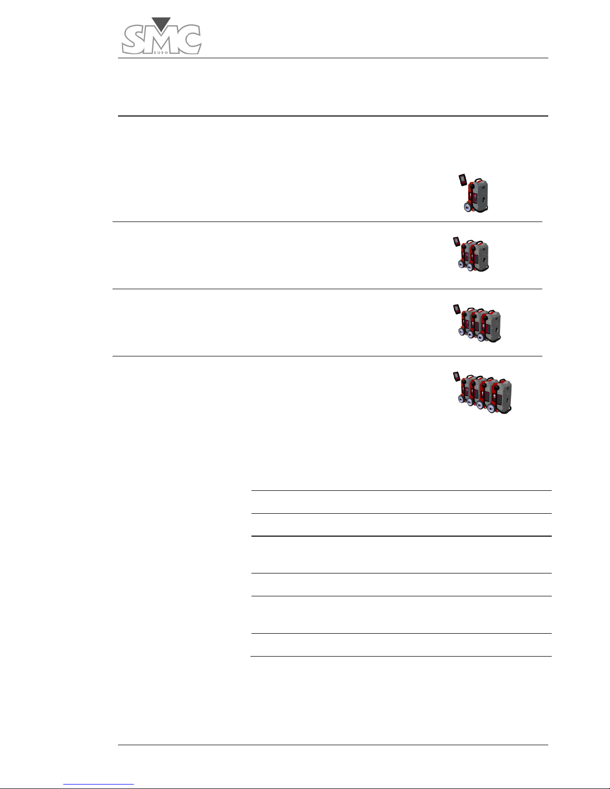
Depending on the system that has been acquired, the following units will be included:
Raptor C-05 1 Raptor-MS Master Unit
1 Raptor-HH Control Console
Raptor C-15 1 Raptor-MS Master Unit
1 Raptor-SL Slave Unit
1 Raptor-HH Control Console
Raptor C-25 1 Raptor-MS Master Unit
2 Raptor-SL Slave Units
1 Raptor-HH Control Console
Raptor C-35 1 Raptor-MS Master Unit
3 Raptor-SL Slave Units
1 Raptor-HH Control Console
The following is included with each unit:
Raptor-HH
1 Raptor-HH Unit
1 Ethernet cable, 2-m long
1 USB connection cable, 2-m long
1 universal power supply (100-240 VAC), with a 7.5-VDC
output
1 stylus for touch screen
1 cable for connecting the Raptor-HH to the Raptor-MS, 3m long
1 nylon protective cover
Page 10

Raptor
10
Raptor-MS
1 Raptor-MS Unit
1 power supply cable, 3-m long
1 cable for low-level measurement, 2-m long
2 pairs of connection cables (red-black), 2-m long
1 set of clips (red-black), medium, alligator type
1 set of 3 small clips, alligator type
2 spare fuses for the power supply
2 spare fuses for the auxiliary outputs
1 nylon protective cover
1 Calibration Certificate
Raptor-SL
1 Raptor-SL Unit
1 power supply cable, 3-m long
2 spare fuses for the power supply
1 nylon protective cover
Page 11
Users Guide
11
SAFE USE OF THE EQUIPMENT
Before using the equipment, you must carefully read this manual, especially this section,
which refers to the safety precautions that must be observed.
Symbols used
Danger – It identifies actions and situations that represent
risks to the user.
Caution –
It identifies actions and situations that could cause
damage to the equipment.
Important –
It identifies actions and situations in which special
attention must be paid
to correctly conduct a test or take a
measurement.
Dangerous Situations
Danger –
Before changing the power connections or the
power supply, be sure that the system is turned off (by
deactivating the power switch of each unit).
Danger – After inje
cting high current, the cables and
connections could be very hot and could cause burns.
Danger – Do not manually open a circuit through which
current is flowing, given that high voltages could be
generated.
Danger – Never connect the power supply cables to a line
before connecting to the equipment.
Page 12
Raptor
12
Danger – When conducting resistance tests, be sure that the
circuit is earthed to some point. If it is a switch, one of the
sides must be connected to earth and the switch must be
closed.
Danger – Before injecting current on the primary of a current
transformer, be sure that its secondary is closed. Otherwise,
high voltages may appear.
Danger – Never operate with the system if you observe
severe damage to it or humidity on it.
Hazardous situations for the Raptor system
Caution – In systems with Raptor-
SL units, when preparing to
conduct injections by pass-through turns, be sure that all the units
are powered.
This is necessary so that the thermal protection
systems work correctly.
Caution – Do not inject using the pass-through turn simultaneously
with the auxiliary output.
Caution – Do not try to lift the equipment using the fold-down
handle. Instead, use the top handle.
Page 13

Users Guide
13
INTRODUCTION
The Raptor marks the difference with respect to any primary injection testing equipment
that currently exists. Its innovative design and cutting-edge technology allow substation
commissioning and maintenance tasks to be carried out more efficiently, given that the
concept of manageability is taken to extremes that were previously never possible to
reach.
With the Raptor, SMC opens the door to a new generation of testing equipment based
on the formula of innovation, designed with and for the user and endorsed by more than
25 years of experience developing practical, affordable and long-lasting solutions for its
customers around the world.
As high-current injection equipment, the Raptor’s design fulfils three fundamental
objectives: 1) being able to bring equipment as close as possible to the device under test,
2) controlling current automatically and 3) only requiring one person.
The basic system (C-05) or ‘master unit with console’ is extraordinarily compact and
manageable equipment, with a touch-screen console that allows making precise
electrical measurements and conducting multiple types of testing, including high-current
testing, for which it uses an elegant implementation of the secondary pass-through
technique. A single conductor passes through the equipment from one side to the other
in order to transmit the current to the object being tested, connected at its two ends. This
saves preparation time and eliminates power losses. The wave shape, of variable
frequency, is generated digitally and is extracted through a 3-kVA power amplifier with
extreme precision and control, insensitive to the variations that might occur in the load
and even in the power supply voltage.
The Raptor slave units, externally identical to the master unit, allow increasing the
injection power in 5-kVA steps just be aligning them with the master and passing the
injection conductor through the entire assembly. A sophisticated power management
system, supported by a robust infrared communications channel, allows managing up to
five Raptor units as if they were a single unit and without having to connect them to each
other, thereby reaching an injection power of over 18 kVA and a current of up to 15,000
amperes. In addition to all this configuration flexibility, there is the possibility of increasing
the applied voltage simply by looping the conductor around the equipment several times.
The Raptor is managed using a small touch screen, which attaches magnetically to steel
surfaces for greater convenience. Updateable by a direct connection to Internet, this
powerful, multilingual controller also stores testing templates pre-configured at the
factory, in addition to those defined by the user, as well as the testing results. Its software
includes an assistant to determine the Raptor configuration and the necessary cable
characteristics for conducting a specific test, even before leaving the office.
Page 14
Raptor
14
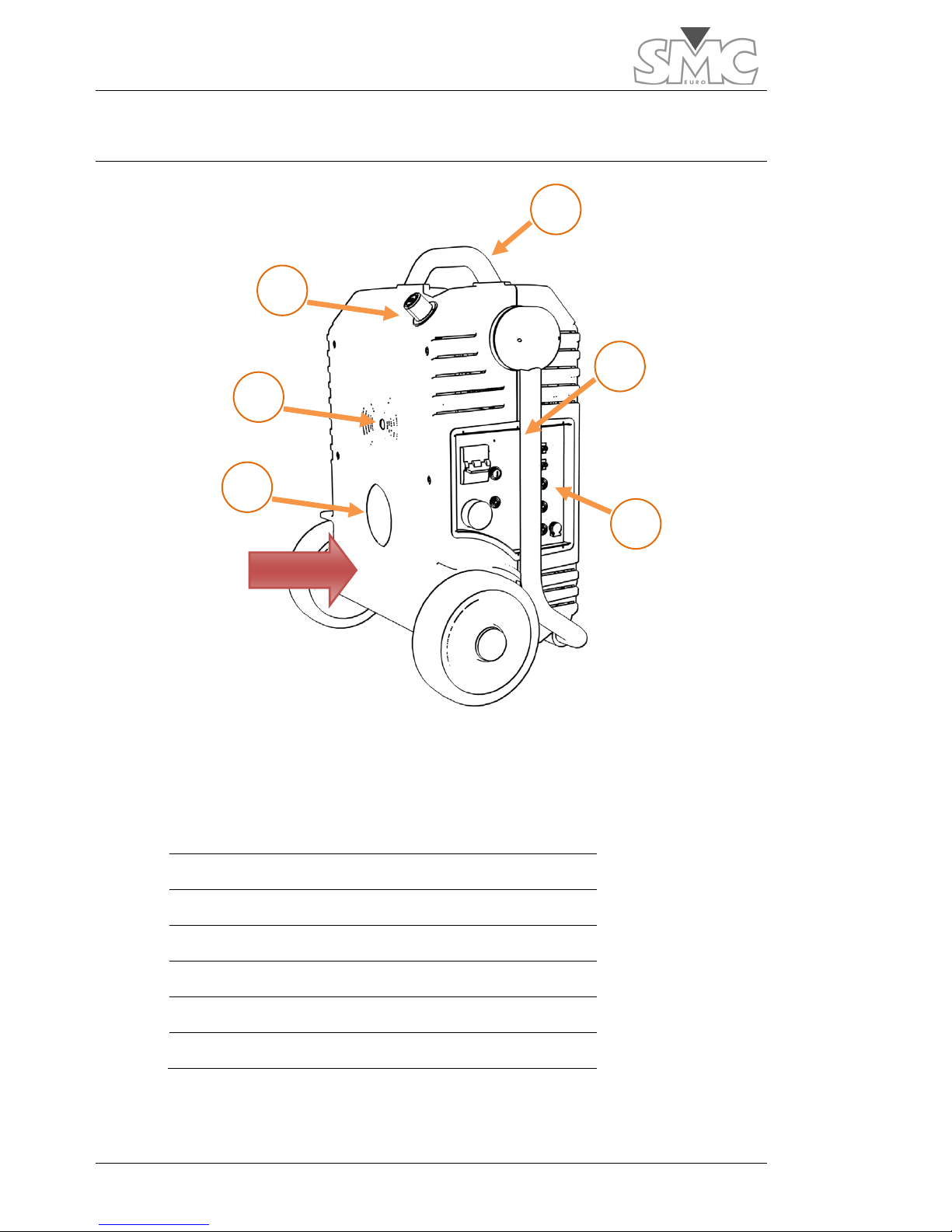
LOCATION OF ELEMENTS
1 Fold-down handle lock control.
2 Infrared communications port
3 Top structural handle
4 Fold-down transport handle
5 Control panel
6 Hole for pass-through turn
Rear Rear part of the equipment
1
6
3
4
5
2
Rear
Page 15
Users Guide
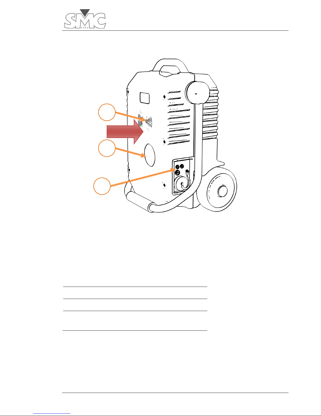
15
2 Infrared communications port
6 Hole for pass-through turn
7 Expansion panel
Front Front part of the equipment Phase
reference for the pass-through turn.
2
7
6
Front
Page 16
Raptor
16
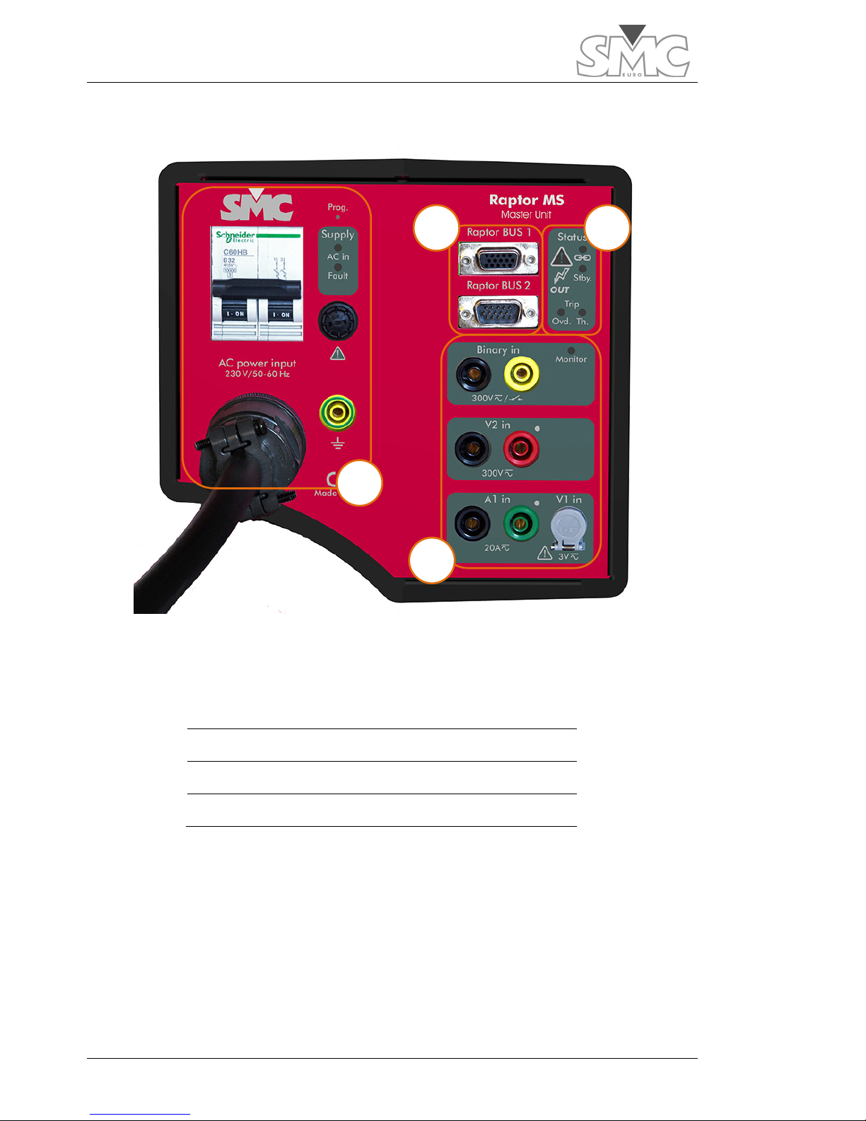
Raptor-MS (Control panel)
1 Power supply control
2 Console and expansion connectors
3 Status indicators
4 Measurement inputs
1
2
3
4
Page 17
Users Guide
17
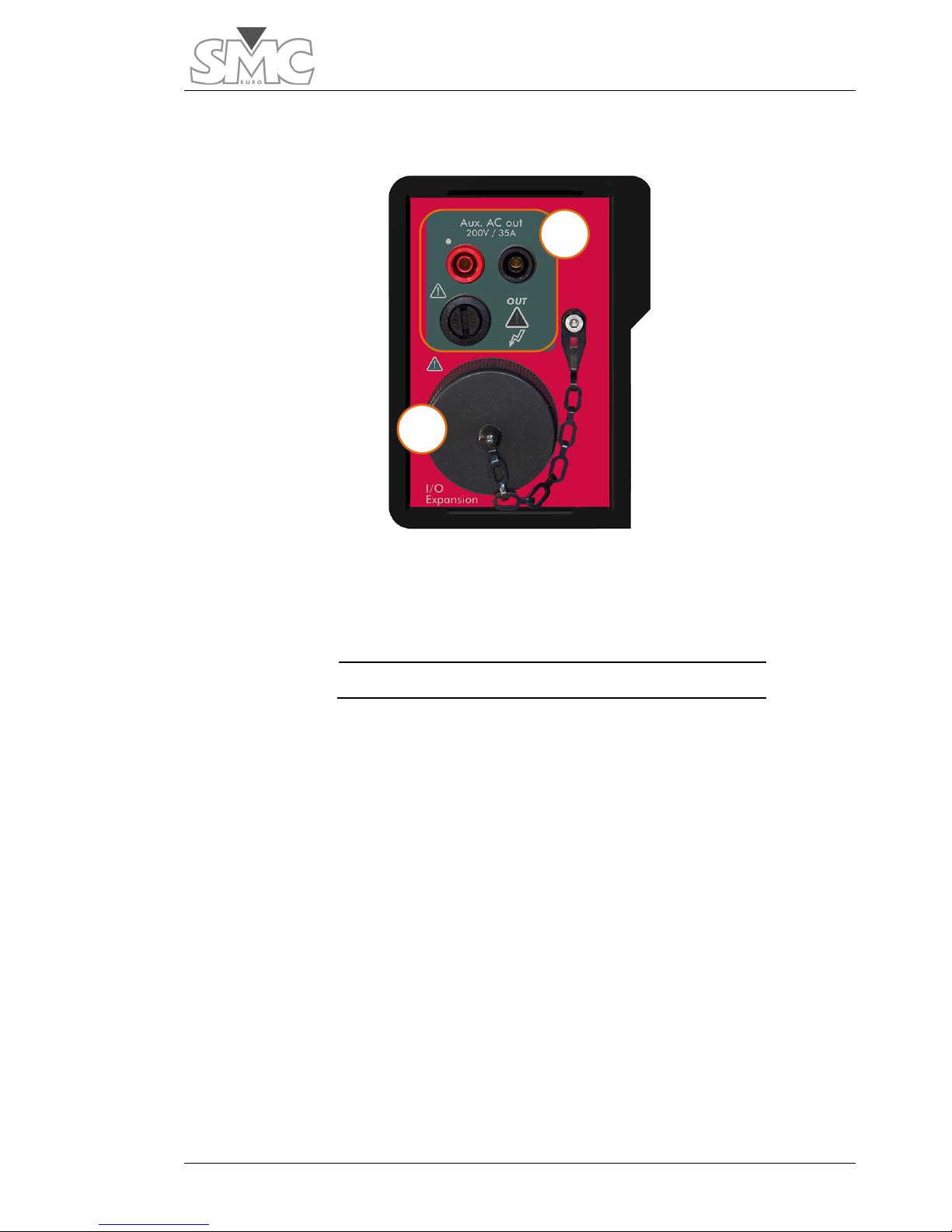
Raptor-MS (Expansion panel)
1 Voltage and current auxiliary output
2 Expansion connector
1
2
Page 18
Raptor
18
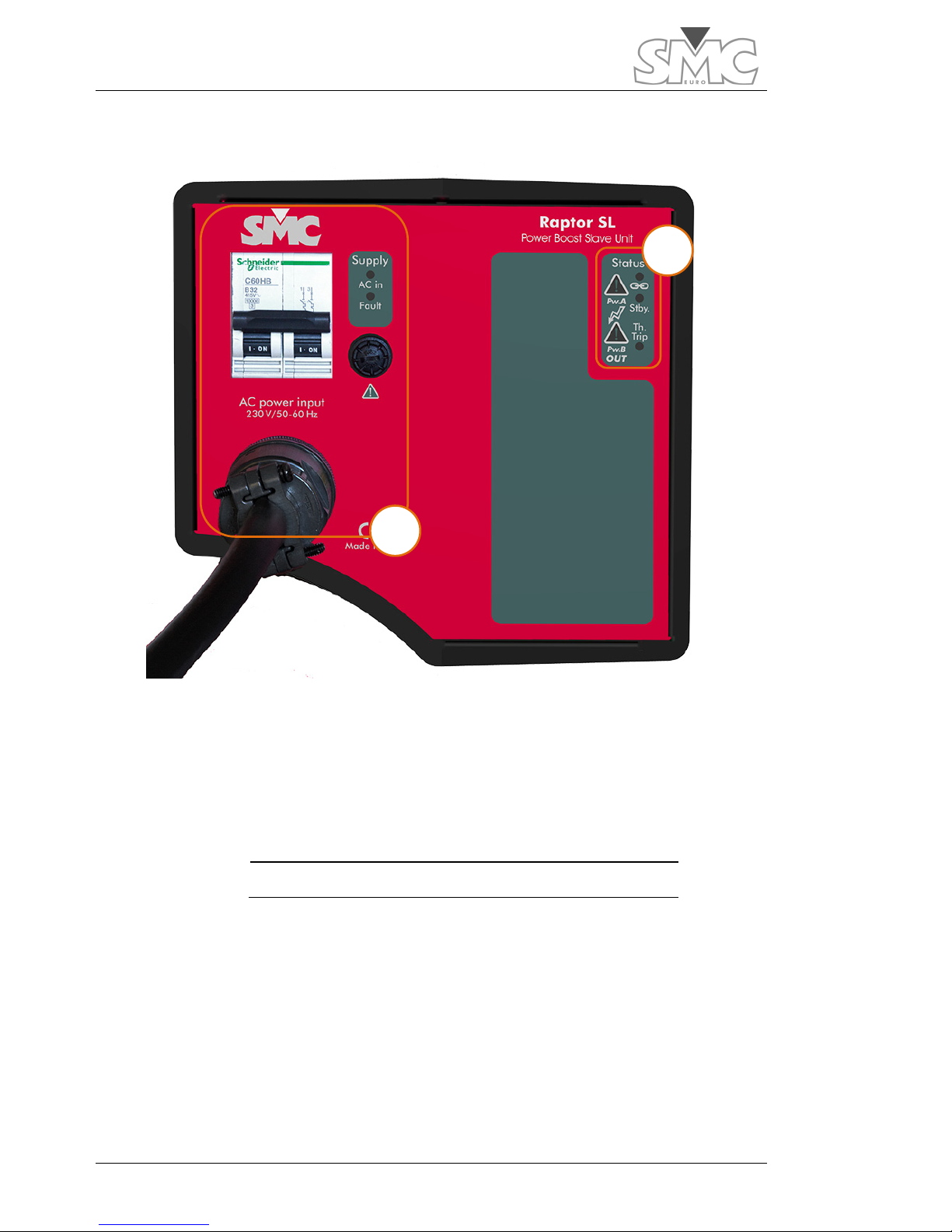
Raptor-SL (Control panel)
1 Power supply control
2 Status indicators
1
2
Page 19

Users Guide
19
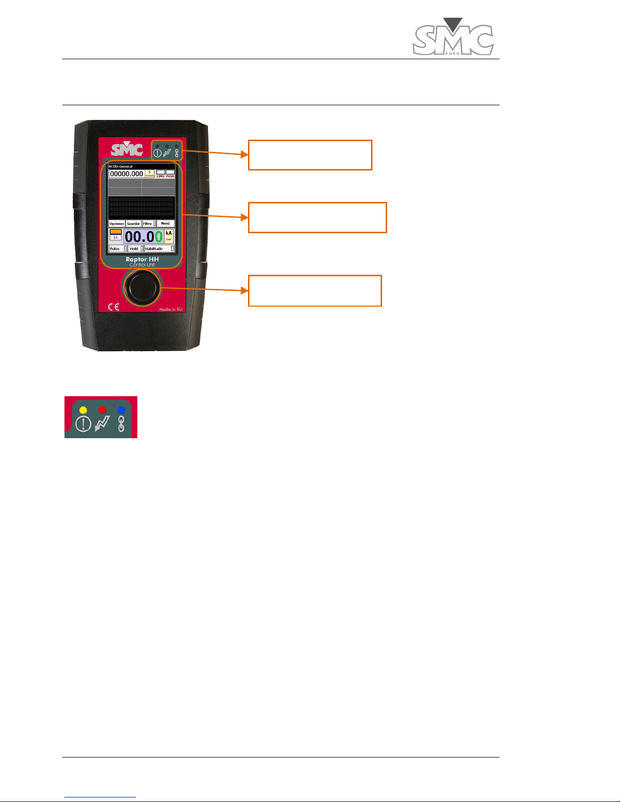
Raptor-HH
1 Top connection panel with USB, Ethernet
and power input
2 Touch panel
3 Status and alarm LEDs
4 Rotary and push button control
5 Bottom connection panel and stylus slot
1
2
3
5
4
Page 20

Raptor
20
HOW TO CONNECT THE SYSTEM
The Raptor system will be composed of at least one Console (Raptor-HH) and one
Master unit (Raptor-MS). Depending on the configuration that you have acquired, you
can also align up to 4 slave units (Raptor-SL).
To connect the system, you must first set up a power supply line with sufficient power/
cross-section to cover the power that your load requires, plus the losses of the generator.
Even though this is difficult to know in advance, you can take into account the maximum
admissible consumption per unit:
Raptor-MS: 18 A permanently, 36 A for 3 minutes and 72 A for 3 seconds.
Raptor-SL: 26 A permanently, 52 A for 3 minutes and 104 A for 3 seconds.
You must keep in mind that the Raptor gives maximum power when fed at 240 VAC,
measured at the start of the supplied power supply cable. To the extent that this voltage is
less or drops during the test, the maximum current or maximum voltage will also drop.
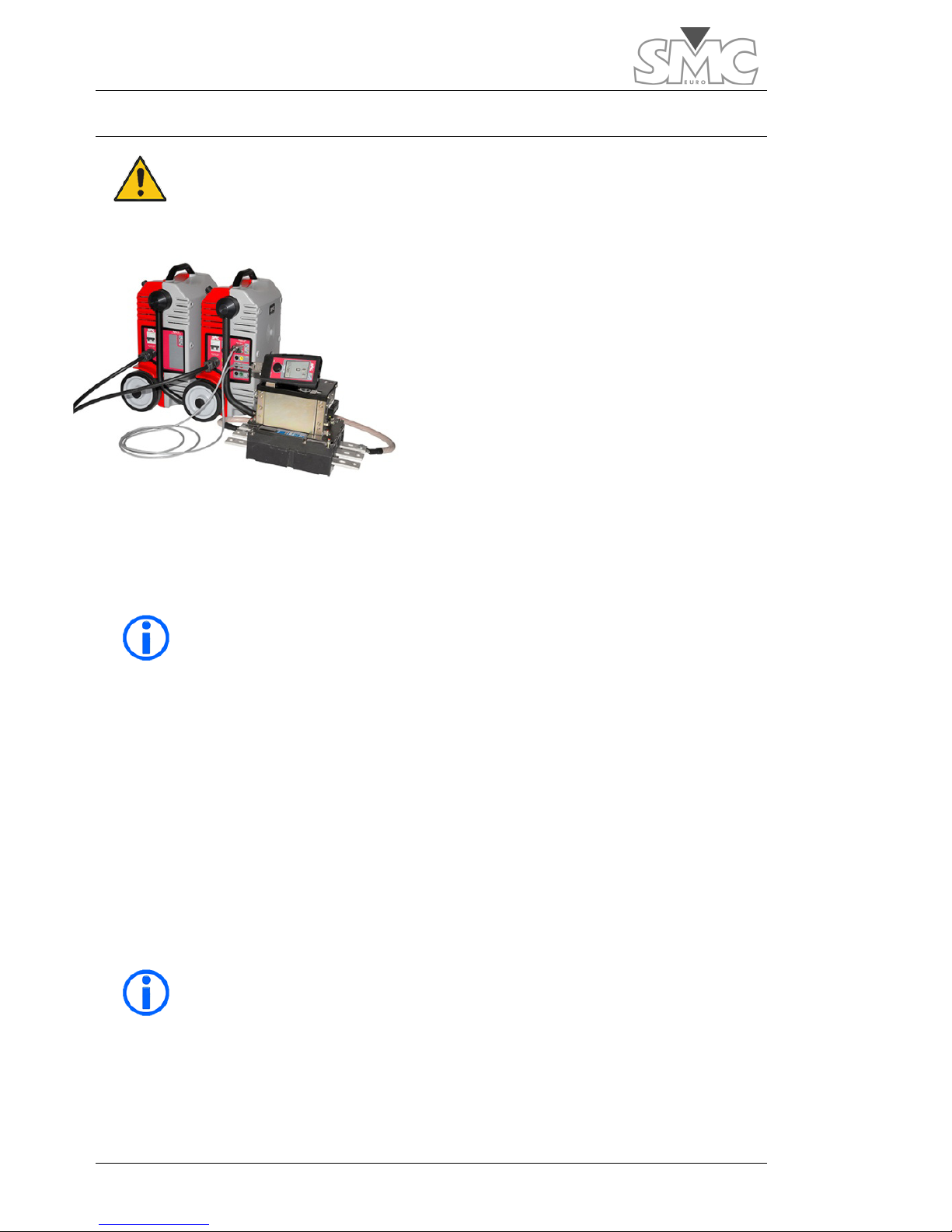
Positioning of the equipment
When preparing to inject current using the ‘pass-through turn’, you must align the Master
case with the Slaves.
This makes it easier to pass the cable through the hole of each unit and allows the
infrared communications channel of the Raptor units to work correctly (this
communication, in both sides of units, is designed for being viewed directly and at a
distance of less than 1 meter).
Conversely, if you are going to use the auxiliary Voltage/Current output, be sure that
there is no closed pass-through turn.
Do not use the auxiliary output at the same time as injection by
pass-through turns.
Page 21
Users Guide
21
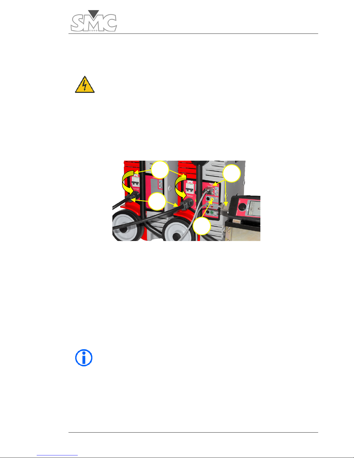
Make the connections
Before continuing, be sure that the main switches of each unit are in the Disconnected
position.
Connect the earth cables present on the power supply
cables of the Raptor-MS and Raptor-SL units to each other
and to an adequate earth.
Make the necessary connections, both injection and measurement. These connections
will vary according to the nature of the test, which in some cases will be detailed later in
this manual.
Connect the Console (Raptor-HH) to the Master case using the cable provided.
Now connect the Raptor-MS and Raptor-SL units to the power supply. Do not make this
connection permanent, due to the fact that if several units are combined, the system
requires that all the units be connected with the same polarity. There is no need to be
concerned, because if the polarity is not the same, the system will detect it and will
indicate on which ones the polarity must be changed.
The polarity is the position of the line and the neutral on all the units. The polarity of
reference will be given by the polarity of the Raptor-MS unit.
You will not be able to work with the equipment until all the units
are connected with the same polarity.
2
3
4
1
Page 22
Raptor
22
TURNING ON THE SYSTEM
Raise the main switches of each one of the units forming your Raptor system. The correct
polarity and power supply status can be checked through the indicators on the control
panel of each unit.
AC in
green LED must remain On from the moment you power up the unit with the circuit
breaker. Otherwise should check the line power, breaker, fuses etc.
Fault
yellow indicator, when remain On, indicating a fault in one of the machine's
internal supplies or line level too low for proper operation of the unit.
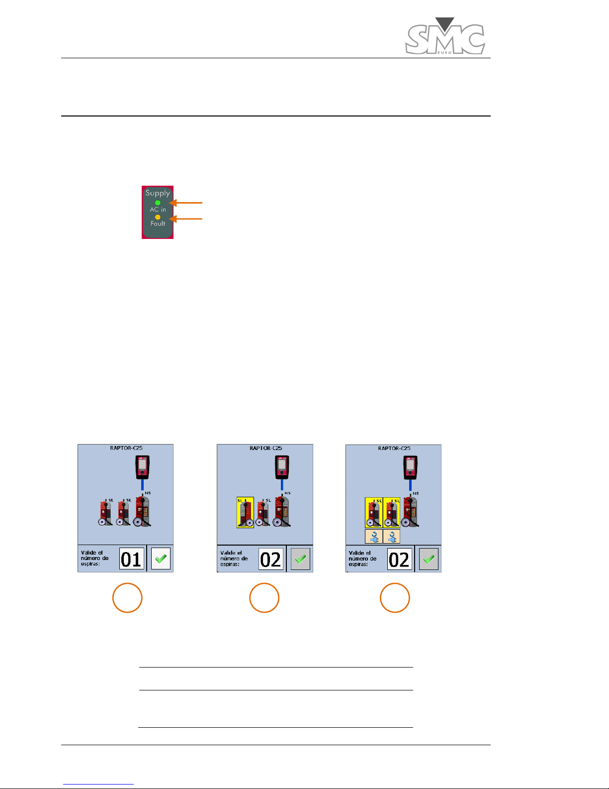
After turning on the system, it begins with system identification by the Raptor-HH unit. The
identification screen graphically shows how the system is connected. If any unit has been
connected erroneously, with the polarity of the line inverted or the polarity of the unit
inverted, this will be shown in the system’s detection window. This error is also indicated
by flashing of the Fault indicator on the case where the polarity is inverted with respect to
the master case. Any connectivity error will not allow working with the system until the
correct connection is made.
1 Units connected correctly.
2 Orientation error of a unit.
3 Polarity error in the power supply of two
units.
1 2 3
Green LED -> Right
LED off -> Right
Page 23

Users Guide
23
With the system detected as stable, all the units comprised in the
same display their connectivity indicators (blue indicator) as permanently
illuminated, thereby indicating that they were detected and recognised by the
system. If this were not so, the unit would be flashing and would not be
recognised by the system.
Stby
indicator red, indicating that the unit is in a state of maximum protection. In this
state remain at power, before any alarm (thermal, communications, power supplies,
overhead, etc..) And at a reset.
Trip Ovd
yellow indicator, (only present in the unit Raptor-MS) indicates an overload on
the output, this can be due to various causes such as load value too high etc.. This
indicator will be deleted when activating power and in case of persistent overload it will
activate again.
Trip Th
yellow indicator, indicates thermal overload in the unit. While this indicator stays
On will not be possible to power up the output. When the unit returns to the proper
working temperature it will deactivate.
In Raptor-MS unit, there are two
OUT
red indicators, one on the main panel and one on
the expansion panel. The first is general and indicates that the power is on, regardless of
the mode of generation selected. The one in the expansion panel indicates that the
auxiliary output is active.
In Raptor-SL unit, there are two but in this case indicate which of the two internal
transformers are active.
With the system stable, the identification window reports the detected system according to
the number of units comprised in the system (Raptor-C05, Raptor-C15, etc.).
The only part of the system that cannot be detected is the number of turns that form the
pass-through winding. Using the system detection window, you will have to enter the
number of pass-through turns with which you will work. If you do not yet know or are
going to work with the auxiliary output, validate the existing number. You can change it
later. Press the dial to accept.
Page 24
Raptor
24
AN INITIAL VIEW OF THE CONSOLE
The status LEDs
The alarm LED (yellow) will indicate the presence of an alarm in the
system. There are two types of alarms: critical alarms and non-critical
alarms. Critical alarms are those for which the system prevents power
from being supplied, such as an overload of the output, a thermal overload, etc. When
such an alarm occurs, the LED will remain illuminated permanently. Non-critical alarms
are those that are not destructive, and it is possible to continue working with the
equipment, such as range saturation of the external meters. When this type of alarm
occurs, the LED will remain flashing. Activation of either type of alarm will be
accompanied by three beeps.
The power LED (red) will indicate the activity status of the output power.
The connectivity LED (blue) indicates that the Raptor system has been detected and is
stable when it is illuminated permanently. When this LED is flashing, it indicates that the
Raptor system is not stable with respect to connectivity.
The status LEDs
Main touch screen
Dial and Key
Page 25
Users Guide
25
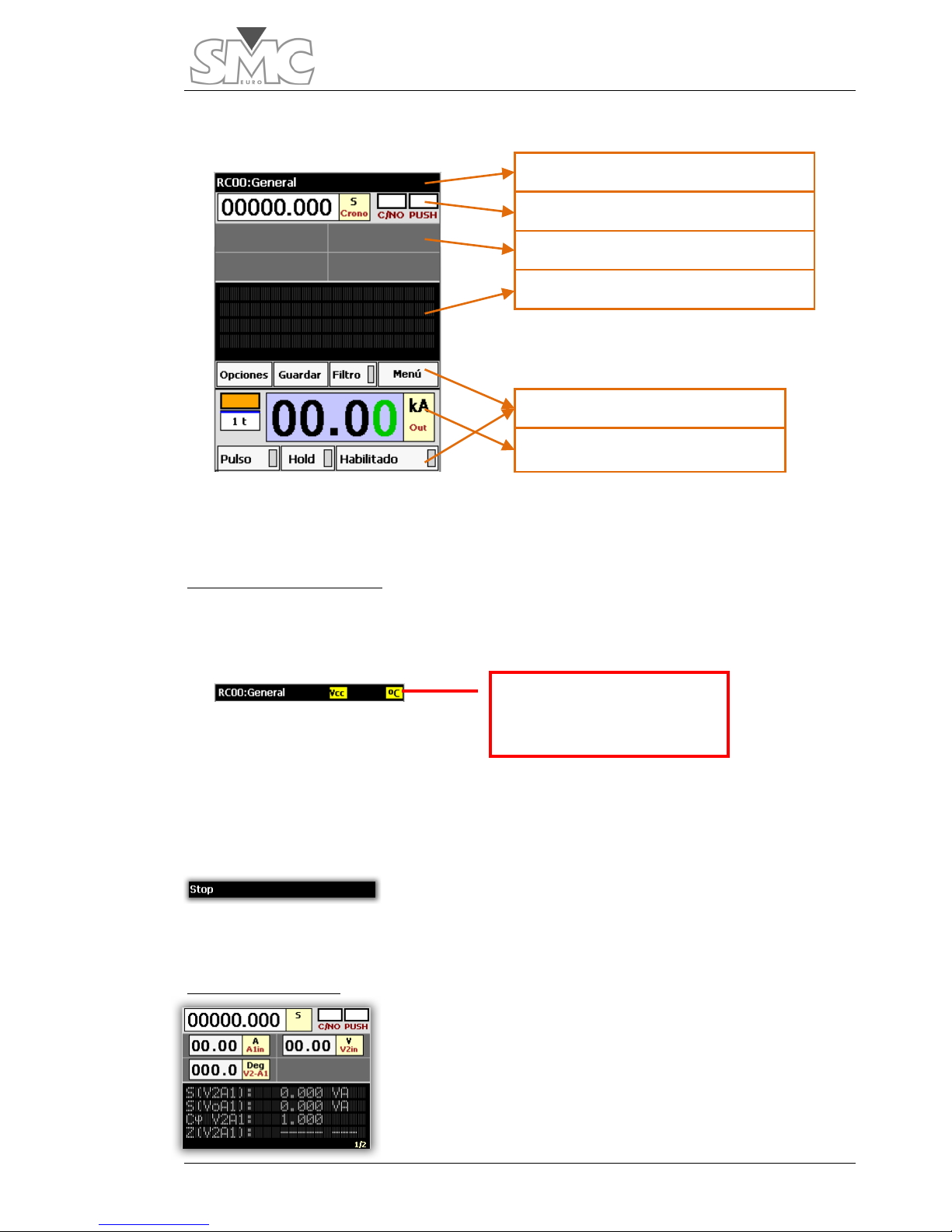
Main touch screen
The main screen is divided into three main zones according to their functionality: Help
and alarms scroll bar, measurements and injection.
Help and alarms scroll bar
This zone has a dual functionality: showing a help text for some parts of the screen and
showing the alarm indicators.
Alarms. The alarm indicators are displayed in this zone. There is an indicator for power
supply failure (
VDC), Temperature (º C), line voltage (Vln) and overload (Ovl). The
indicators are highlighted with a yellow background. The preceding image shows some
indicators.
Help texts. When tapping on certain controls of the screen,
an indicative text of their function is shown for a few
seconds, thereby replacing the name of the system. The image shows the text after
tapping on the Stop indicator.
Measurements zone.
The controls that show the measurements taken by the
equipment are located here. They can be
hardware
measurements (direct readings made by the Raptor-MS) or
calculated
measurements (processed based on
hardware
meters). You can modify the meters you want to be displayed
Indicator with temperature
alarm
Information and help area
Chronometer and binary inputs
Hardware measurements
Calculated measurements
Injection zone
Auxiliary commands
Page 26
Raptor
26
at any time, although two of them (the time meter and the stop condition) are always
visible.
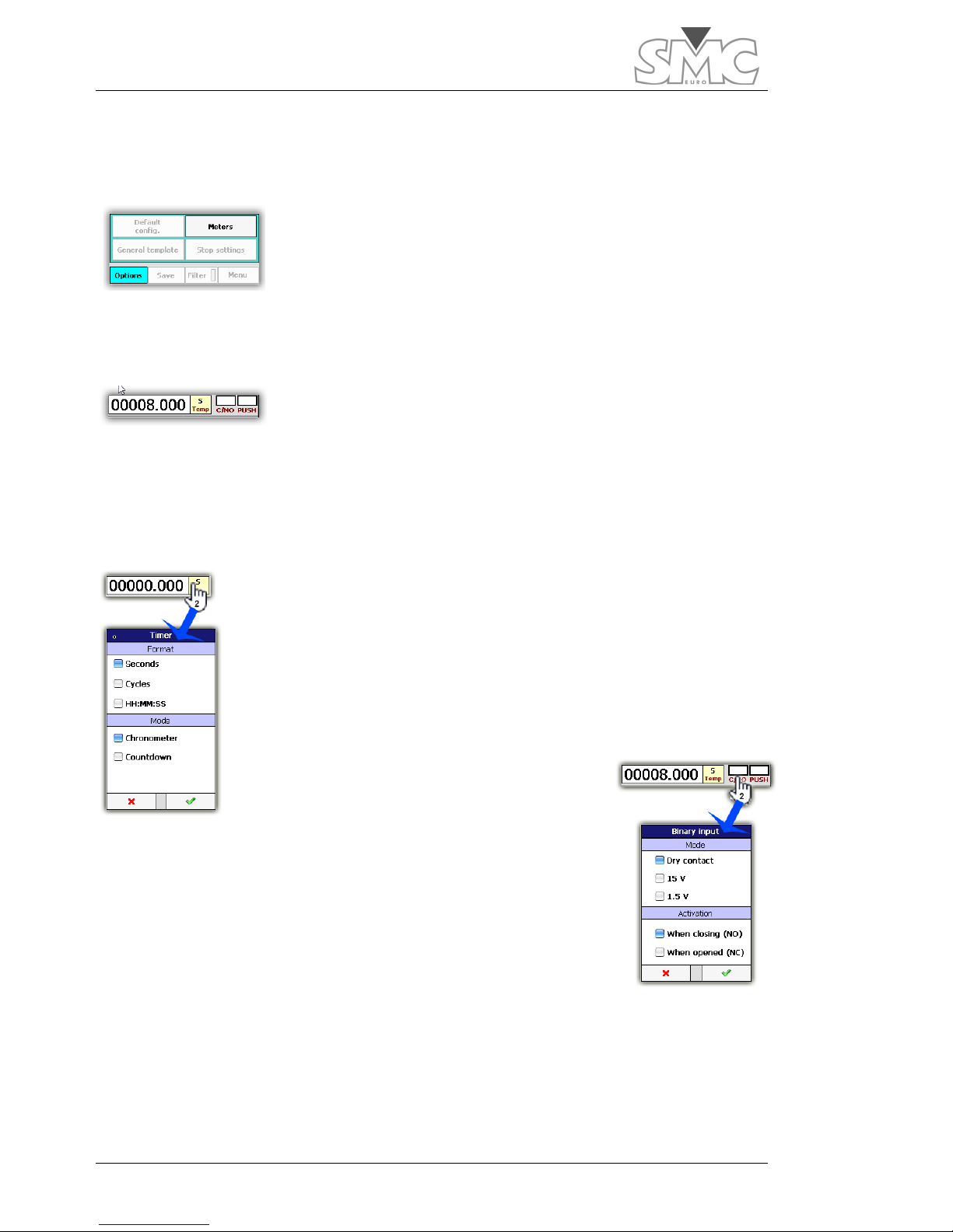
Meter selection.
To add or remove meters, tap on the
options
button and then
meters.
A screen will be displayed where you can select the
hardware and calculated meters. Many of the meters also have
a button on their right-hand side to access the meter’s settings. A
maximum of four
hardware
meters can be displayed. There is no limit to the number of
visible calculated meters.
Time meter.
It shows the time elapsed as from the moment when power
generation starts until it turns off or until the configured stop
condition is reached. This meter is always visible.
It can be displayed in seconds, in cycles or in the HH:MM:SS format, and it can work as
a chronometer or a timer. When working as a timer, generation is shut down when zero
is reached.
To configure the time meter, tap twice on the time control, and you
will access the options window.
Binary input indicator
It shows the status of the binary input. The indicator lights up red
when it is active.
And it is white when inactive.
To configure the binary input indicator, tap twice on the control.
In Mode section you can select between dry contact or voltage input. In voltage mode
can choose between two detection thresholds. These levels do not indicate the maximum
voltage level applied to the input, which is 250V.
Page 27

Users Guide
27
When Dry contact mode is assigned, if the voltage applied to the binary input exceeds
18-20 V DC the machine is protected changing mode automatically to Vmode high (15
V). Upon this protection, you are warned by alarm indicator overload but it is a
momentary display, as when it changes to voltage mode, the alarm disappears. For this
reason, the EB status indicator is displayed flashing to be aware of the event. To remove
this blink situation, you must enter the EB setup window and validate the new settings by
clicking OK.
Stop condition indicator.
It is activated when the selected condition for stopping the test
has been met. The indicator lights up green when activated.
Otherwise, it lights up white. When the stop condition is
activated, all other visible meters go to the Hold status.
To configure the stop condition, tap twice on the indicator or
select the
options button and then the Stop Conf. button.
Hardware meters
A maximum of four meters can be displayed.
To configure the hardware meters, tap twice on the meter control
or access configuration from the meter selection window. The phase meters do not have
a settings screen.
Calculated meters
There is no limit to the number of calculated meters that can be
selected. If the number of selected meters is large, they cannot all
be shown simultaneously. As the calculated meters panel is
tapped, the viewed meters will change. When the last view is
reached, tap again and it will return to the initial view.
Neither the configuration nor the visibility of any meter can be
modified while HOLD is active or the output control is enabled.
Page 28
Raptor
28
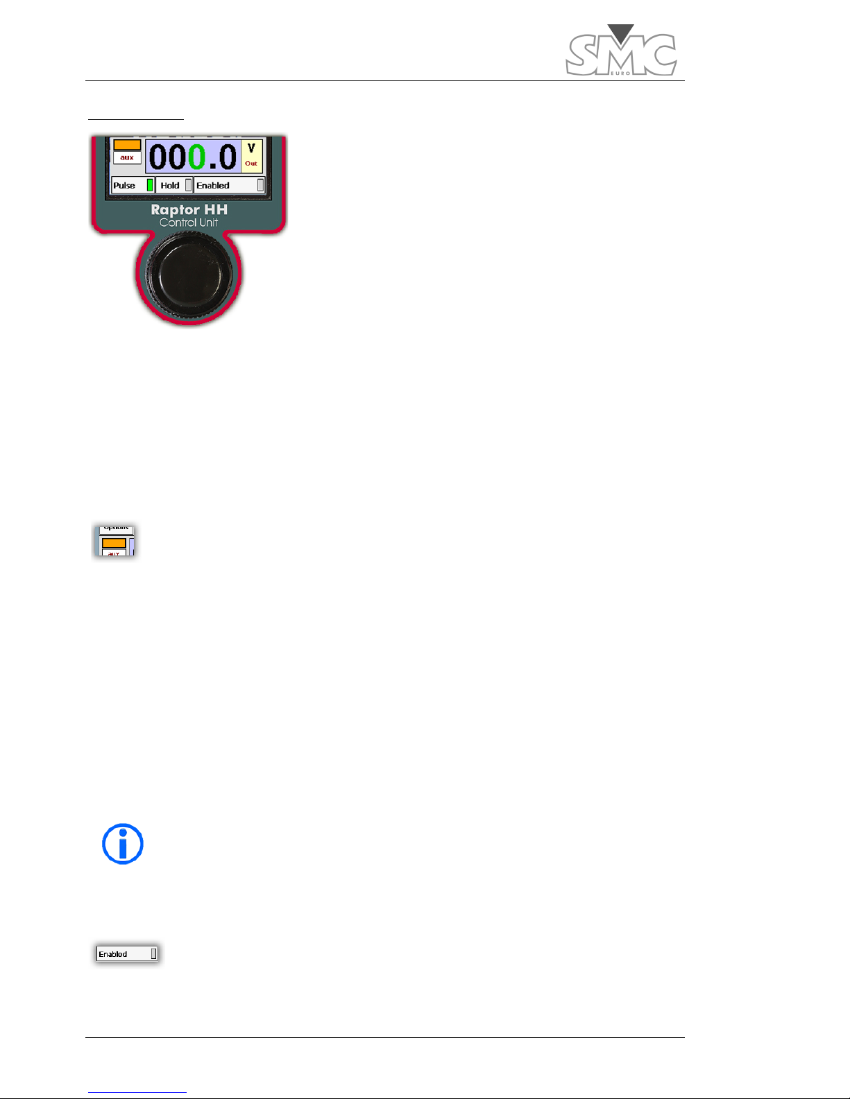
Injection zone.
This is where the controls and indicators related to power
generation are located.
Generation level
This control is used to assign the level to be generated. To
be able to modify the value, the control must be selected. To
do so, tap on the control. The background will change to blue,
and a digit will be displayed in green, thereby indicating that
this is the digit that is going to be modified (active). To change the
active digit, simply tap on the new digit.
If power is being generated, the right-hand part of the control lights up red.
To change the generation settings or to modify the generation mode, tap twice on the
generation control.
Pre-injection indicator
It indicates that in the next start-up, it will initiate with a low value level for a
brief period of time in order to determine the connected load. Once this is
done, it will be disabled for the following start-ups.
If active, the indicator will light up orange.
Pre-injection is activated automatically in the following conditions:
• When changing the configuration or the generation mode.
• When 5 minutes elapse without having generated power.
• When the console is initiated.
Moreover, it can be activated manually. To do so, tap twice on the indicator.
Neither the generation configuration/mode nor pre-injection may be
modified when power generation is enabled.
Generation enabling
It indicates whether or not power generation is permitted.
Tap on the enabled button to change the status. If it is permitted, the LED
of the
enabled button will light up green. Otherwise, it lights up grey.
Page 29

Users Guide
29
If generation is enabled, it is not possible to change any of the system’s settings.
Pulse
It changes the mode to control how generation is turned on and off. If it is
active, when the dial is pressed and held, generation is produced, and it is
turned off when the dial is released. If it is not active, the generation is produced the first
time the dial is pressed and it will turn off the next time it is pressed.
Press the Pulse button to activate/deactivate this generation mode. If the pulse mode is
enabled, the LED of the Pulse button lights up green. Otherwise, it lights up grey.
Page 30
Raptor
30
MAKING THE FIRST CURRENT INJECTION
Caution – If injection is going to take place through the auxiliary
output, it is essential to leave the pass-through winding in an open
circuit.
After making the connection sequence as
explained in the chapter on “How to connect
the System”, now the load must be
connected.
The minimum required Raptor System adapts
to each load-environment situation when it
injects on its pass-through winding. While the
number of Raptor units used, the number of
pass-through turns, the length and crosssection of the pass-through cables and the injection range can vary, there is an optimum
combination for a minimum Raptor System. The majority of the application’s controls
open up a window, thereby allowing the controls to be configured by tapping twice on
them.
Important – The most powerful configuration (NOT the optimum
configuration) for a desired current is obtained:
1. By using the greatest possible number of Raptor-SL units.
2. By increasing the number of turns to the maximum, as long as the
maximum selectable current on the Raptor-HH continues to be
greater than or equal to the desired current.
3. By maximising the cable cross-section, thereby attempting to
occupy the largest possible space of the pass-through hole.
4. By minimising the cable length and the intermediate connections
to the load.
5. By braiding the cable both to and from the load.
Important –
The “Current calculator” is a utility included in the
Raptor-HH (also available for a PC), which helps to estimate an
optimum Raptor System for each case.
Page 31

Users Guide
31
Steps to follow
1. Select the pass-through turns.
You must tell the system how many turns have been wound through the central hole. If
this window is not displayed,
you must proceed to step 2
and then return to this one.
2. Select the injection mode and the measurement range.
Initially, you must tell
the system that the
desired operation is
‘Inject current’ and
within what
measurement range it
will work.
You can choose from
between two
measurement ranges.
The limit value of these
ranges will depend on
the number of turns
selected in step 1,
wherefore you must return to this screen if you change it.
3. Chronometer mode
If you are going to take Time measurements, configure the
chronometer. Otherwise, go directly to step 4.
To configure the chronometer:
• Decide if it will work as a Chronometer or a Timer
(count-down). If as a Timer, select the value and
go to the next step.
1 2 3
Page 32

Raptor
32
• If it will work as a chronometer, decide if the
test will stop by pressing the dial, or with the binary input or when
the current circuit is opened. This stop will also cause a hold of
the measurements.
• If the selected stop is by binary input, configure the
action mode.
4. Selecting the value.
By tapping on the digit you would like to change
and using the dial, select the current value that you
want to inject.
5. Decide on the injection control mode.
You can choose between Pulse mode activated or deactivated. In the
activated mode, injection takes place while the dial is pushed and
held. In the deactivated mode, injection begins when the control is
pressed and ends when it is pressed again (or when the
chronometer stops).
Important – If the pre-injection software LED is illuminated when ON is
pressed, the level requested by the user will be preceded by a transient
(~100 ms.) to detect the connected load and to be able to SELFREGULATE. The Raptor System will not compute the times in these cases.
Page 33

Users Guide
33
6. Enabling injection.
Tap on the button to enable injection. This function prevents
the dial from being accidentally pressed.
7. Injecting.
Press the dial and control injection according to the selection
made in step 5.
Current injection may end early due to:
• The chronometer stopping.
• An excessive load.
• Internal time limitation according to the current.
• Having configured the chronometer in the ‘Count-
down’ mode and the count has reached zero.
Caution – Never leave the equipment injecting without direct
supervision. If you have under-sized the cross-section of the
pass-through turn, the insulation could melt.
Important – With injection disabled, the Raptor System will
not generate through its outputs. If it is enabled, other
actions will be prohibited.
Page 34

Raptor
34
AVAILABLE MEASUREMENTS
The Raptor system has broad measurement capacity. On the one hand, it has the
capacity to measure times, and on the other, various electrical magnitudes. This second
group has been divided into three types. The first type are measurements called Internal
Measurements, used by the system to adjust injection. The second type are ‘Hardware’
measurements, which are those obtained through specific electronic circuits included in
the Raptor-MS case. The third type, ‘Calculated’ measurements, is obtained through
calculations based on the Internal and Hardware measurements.
Internal measurements
These measurements are related directly to the injected magnitude, and they are not
directly visible, given that they are those that the processor uses to adjust the injected
magnitude selected by you.
The main current meter is a Rogowsky type of sensor included in the Raptor-MS case,
which surrounds the hole where the pass-through turns are inserted. Due to the
characteristics of this sensor, it measures the total current flow passing through the
system. This is why, when using injection by pass-through turns, you must be sure that the
number of turns specified on the console is the actual number. Even though this type of
measurement is very precise, to improve the measurement the system has 2 ranges,
which you must select. You can access this configuration as described in step 2 of the
chapter, “Making the first current injection”.
When you use injection through the auxiliary Voltage or Current outputs located on the
expansion panel of the Raptor-MS unit, there is also an internal measurement of these
magnitudes. This is a low-accuracy measurement, of around 5%. If you require greater
precision, it is advisable to simultaneously use the external meters to compare the real
injected value.
Hardware measurements
In addition to the binary input related to the chronometer, the
main panel of the Raptor-MS unit has three measurement
inputs, two for voltage and one for current.
These inputs are connected to level sensors on one side and
are taken by pairs (including the internal measurements) to
phase sensors.
The
A1in
current input shares circuitry with the
V1in
low-voltage
input, and they both cannot be used as the same time. An
orange zone on the selector indicates which one is active (even
though it may not be selected for display).
The ‘Hardware’ measurements are obtained based on these
sensors.
Page 35

Users Guide
35
Eight ‘Hardware’ measurements are available:
• High level external voltage measurement. (V2in)
• External current measurement (A1in).
• Low level external voltage measurement (V1in).
• Phase measurement between V2in and A1in.
• Phase measurement between V2in and V1in.
• Phase measurement between V2in and Iout (output current).
• Phase measurement between A1in and Iout.
• Phase measurement between V1in and Iout.
Given that A1in and V1in cannot be used simultaneously, as stated, only 6 of them can
be selected for display in each case.
The following image shows the A1in and V2in meters:
The ‘Hardware’ measurements zone has four display cells. Therefore, there are a
maximum of four ‘Hardware’ measurements that can be viewed on screen at the same
time. The cell occupied by each added measurement doesn’t always have to be the
same; it depends on which and how many meters you may have added.
A measurement of this type shows three different data:
V2in measurement
Space to add measurement
Page 36

Raptor
36
If the value of the measurement is in blue, it indicates the automatic range setting.
To select the ‘Hardware’ measurements,
proceed as indicated in the figure.
It can be seen in the image, that the
‘Hardware’ measurements are selected.
The ‘Calculated’ measurements are
described in the next section. There are two
selection pages.
The green/grey LED of each meter indicates if the measurement is selected for display.
To access the measurement setting, tap on
The A1in, V1in and V2in measurements are configured as follows:
The transducer mode allows you to adjust the magnitude shown on screen to the
transducer’s conversion characteristics, thereby allowing the units, scale and offset to be
changed.
Phase measurements have no configuration.
DC mode and peak measurement
Measurement range or Auto mode
Display by nominal %
Transducer mode
Measurement units
Measurement input name
Measured value
Page 37

Users Guide
37
Calculated Measurements
Based on the aforementioned Internal and Hardware
measurements, the calculated measurements are obtained
through calculations.
Up to 4 measurements are shown on each page. The number of pages of Calculated
measurements will depend on how many have been selected. The current and total
pages are shown in the lower right-hand corner. To move from one to another, tap on
any part of the black zone.
To select the ‘Calculated’ measurements,
proceed as indicated in the figure.
There are 8 possible types of measurements:
Apparent power
Reactive power
Total power
Power factor
Impedance
Reactance
Resistance
Transformation ratio
Only the ratio measurements have configuration available. Tap on
If you activate the option, ‘Show as a nominal error’, the screen will
show the ratio error with respect to the ideal that you must configure
in the table that will be displayed.
Page 38

Raptor
38
Functions related to measurement
Hold button. After tapping on it, the values of the measurements
are maintained, both ‘Hardware’ and ‘Calculated’
measurements, in addition to the values shown on the chronometer and the binary input.
If it were already activated, by tapping on it, the meters would be released and the
currently measured values would be shown. This mode is activated automatically when
injection is stopped due to the Stop condition having been selected. With a new injection,
this mode is deactivated automatically.
Filter button. It allows activating the average of measurements,
thereby allowing them to be stabilised in noisy environments.
Measurement averaging is for 5 seconds. However, this cycle re-starts as soon as the
variation of the measurement exceeds a certain threshold. Thus, even though this
function may be active, tracking in the event of changes is quick.
Page 39

Users Guide
39
OBTAINING THE TEST REPORTS
The Raptor system is equipped with the capacity to save the results of tests for subsequent
review or for printing the test reports through the RaptorSync programme (for a PC).
Concept of Report and Test.
A test encompasses all the testing performed, including: the measurements that may be
configured for display on screen, the measured time, the injected level and, in general,
all adjustments and alarms.
The report is a grouping of the tests under a common name and comment.
How to use the Reports and Tests.
To activate the capacity to save the results of a test, you must
have previously a report open. You can know if you already have
a report open by the status of the
Save button. If it is disabled, it
indicates that no Report is already open.
To open a report:
Tap on Menu and then browse to the Reports icon, either using
the arrows and tapping on the icon or using the dial and then
pressing it.
If the Close button is active, it means that a
report is already open, whose name will be
displayed at the bottom. To create a new
one or open an existing one, you must first
close the current one. The report is kept
open even if the system is turned off.
If you decide to create a new one by
tapping on the New button, you will be
asked to enter the name and a brief
description to facilitate subsequent identification.
From the Reports screen, you can also open a report for review by tapping on View, or
you can delete it by tapping on Delete. When a report is deleted, the tests contained in
the same are also deleted.
With a report open, you can save the Tests simply by tapping on the Save button of the
main screen.
In the submenu, you can save the results of a test without
specifying anything else by using the Save test button, or you can
specify a comment using the Save test with comments button.
You also have a button available for deleting saved tests in
reverse order.
Be careful when using this last button, given that it will not ask you for
confirmation.
Page 40

Raptor
40
When View button is tapped with a Report previously selected, a
new window will open up, where you can review each of the
saved tests. There you have a scroll bar for going from one to the
next. Using the dial, you can move up and down through the
Test.
Using the RaptorSync programme (for PC with Windows)
With your Raptor system, you will have received the RaptorSync application, an auxiliary
feeder cable for the Raptor-HH console and a USB cable. This is all you need to view,
import and print reports from a PC with the Windows operating system.
If you do not have the programme, you can download it from:
64-bit operating systems.
http://eurosmc.com/downloads/RaptorSyncInstaller64.msi
32-bit operating systems.
http://eurosmc.com/downloads/RaptorSyncInstaller32.msi
Install it, but do no run it yet.
Windows XP operating systems
Before being able to use the RaptorSync programme, you must install the ActiveSync
communications utility, Ver. 4.5 or later supplied for free from Microsoft.
Installation of Microsoft’s ActiveSync.
If it has never been installed, proceed according to the instructions provided by Microsoft
for installation, and restart your computer when asked to do so.
After restarting, you’ll see an icon such as the following on the tool bar of your desktop:
By double-clicking on the icon, the ActiveSync programme will open.
Page 41

Users Guide
41
Preparing communication
Once the ActiveSync programme is open, a screen
similar to the following will open. (the screen may vary
according to the installed version)
From the File menu, select
Connection Settings…
The following settings screen will be displayed:
Since you are going to connect using a USB cable, it is
not necessary to mark those settings that refer to the
COM serial port.
Click on OK
Establishing communications
Now connect the console to the PC using the USB cable. Power it using the auxiliary
power supply provided.
If this is not the first time you perform this operation, go directly to the next step.
If it is the first time, a screen such as the following will be displayed:
Select ‘Yes’ and click on the ‘Next’ button.
Page 42

Raptor
42
At this screen, select ‘Files’ and click on ‘Next’.
A message will be displayed, warning that a folder is going to be created on
your desktop. Accept it.
This screen, with the green icon to the right, indicates
that you have successfully finished the connection
process.
Page 43

Users Guide
43
Windows Vista, Windows 7 and Windows 8 operating systems
The first time you connect the console to a PC, you must have an operational Internet
connection. When the Raptor-HH console is detected, the necessary Microsoft software
for establishing communications will be downloaded automatically to your PC.
After installation and restarting your PC, if required, upon connecting the Raptor-HH,
you’ll see the following screen:
You can close it.
Page 44

Raptor
44
Running the RaptorSync programme
Be sure that you have connected the Raptor-HH console, and click on the icon
that will have appeared on the desktop.
This screen will be displayed.
Information and reports of the device.
Two panels can be distinguished:
Information panel:
it shows both hardware information
(available and total memory, available and total storage,
hardware version, etc.) and software information (software
version of the hand-held unit). To access this information
panel, click on the arrow at the header of the information:
Information and
reports on the device
Local database. List and
report viewer
Page 45

Users Guide
45
Reports panel:
it shows the list of reports that exist on the
device. To display this panel, click on the arrows in the reports
header:
Three types of actions can be taken with the reports list:
• Import. It imports the database from the device to a local database. It does not
require confirmation to perform the action.
• Delete. It deletes the report directly from the device. Once deleted, it cannot be
recovered. It requires confirmation to perform the action.
• Show. It shows the report directly from the device.
Local database.
It is formed by two panels:
Reports panel
. It shows the list of reports that exist in the local database. This database is
always visible.
Three types of actions can be taken with the reports list:
• Delete. It deletes the selected report from the database. Once deleted, it cannot be
recovered. It requires confirmation to perform the action.
• Show. It shows the report selected in the bottom panel.
• Save as PDF. It saves the displayed report as a PDF document.
Page 46

Raptor
46
Report display panel.
It displays the report selected in the list of the local database. A Vc Magnetisation test
and its graph can be seen in the following image.
Page 47

Users Guide
47
OTHER POSSIBLE INJECTIONS
The Raptor-MS unit has auxiliary outputs to be able to
inject small currents or high voltages that are essential
in certain tests.
If working with predesigned templates (see chapter
“Management of predesigned templates”), this
selection will be made automatically.
To select the injection mode by auxiliary outputs:
Press
Auxiliary secondary
-.
Then decide if you want the output to
be controlled in Voltage or Current.
Injection ranges cannot be selected in
this mode.
This model will be indicated in the injection control area.
A screen may appear if the mode selection controls are
disenabled. This is due to the fact that you are using a
predesigned template and this template is already establishing
the type of injection.
To permit the configuration in this case:
It is not possible to modify either the configuration/mode or the
generation or the pre-injection when power generation is enabled.
Caution – If injection is going to be carried out through the auxiliary
output it is essential to leave the pass-through winding in open
circuit.
Page 48

Raptor
48
ANTICIPATING THE CURRENT THAT WILL BE OBTAINED
A large number of variables normally intervene in the
generation of currents. Some are common to any
injection system, such as, for instance: length and crosssectional area of the connection cables; load impedance
or the system power supply voltage and others are unique
to the Raptor system, such as: the number of slave units;
the number of turns wound in the pass-through hole; etc.
To make it easier to give a prior estimation of the current it will obtain, the Raptor system
incorporates a powerful calculator as part of the Raptor-HH console control application.
Thanks to this system, a lot of trial and error time, or using an over- or underdimensioned configuration will be avoided. This calculator is also available as a
standalone application executable in PC with Windows O.S.
This has been designed in simulator format, in other words, you enter the data of the
components available or which may be available and the calculator will inform you, at all
times, of the current you will obtain with a considerable degree of accuracy. You can
vary any parameter at any time and the results area (on the second screen) will vary
accordingly.
You can carry out the calculations, only using the console, without the need for other
units, before moving to the test place.
Data entry
The calculator has two screens:
The system supply voltage and the frequency must be
entered in the first screen.
As the resistivity of copper changes considerably, you are
given the chance to choose the system temperature, so that
the results are more accurate. If you are considering
carrying out spaced tests, choose Cold; otherwise, if you are
going to carry out long-lasting or very repetitive tests, choose
Hot.
If you know the approximate load impedance, enter it. If not,
set to 0. The maximum current in this type of test normally
depends on the actual system, more than on the load, which is usually very low.
You may also save the data entered MS and recover them
MR in three memory positions.
Page 49

Users Guide
49
When you have finished, go to the next screen. You can move freely back and forth
between the two without losing data.
The selections are made as normal on the console; tap on
the table you wish to change and use the dial. In some
cases, when a number is highlighted in green, it will be
possible to change it just by tapping on the one you desire.
On the right of five of the parameter selectors, you will see
that the system indicates the maximum and minimum you
can select. The system can automatically rectify the values
entered when you change any of those that these depend
upon, to set them within the limits.
At the top, you must configure the number of Raptor-SL
units you wish to use. For the moment, the number of
Master units is fixed.
The cross-section selector of the cables mm2/cable permits, when by pressing the blue
triangle, shifting between the standard in mm2 and the American standard AWG. The
cross-section you must enter is the cross section of each one of the cables, not the total in
case you are going to use several in parallel.
The No. of cables selector enables you to define how many of them you will use in
parallel. You will see that the maximum indicated varies depending on the cross-section.
If you use the ultra-flexible type of cable that can be supplied as an option with the
Raptor system, you must reduce this maximum by 10% as it is thicker than normal.
The m/cable selector must be used to indicate the length of the cables to be used. The
system uses this information to determine how many turns it can carry out and also the
distance to load, apart from calculating the current. The configuration of Raptor-SL units
is taken into account to determine the length consumed in turns.
The results of the calculation.
Maximum currents. This shows the result in maximum
currents in three work regimes: 3 seconds, 3 minutes and
permanent regime.
The maximum current indicator fields supply another type of information, apart from the
current value.
Page 50

Raptor
50
White background No cable cross-section warning
Orange
background
Warning that for the selected cross-section, the
current density may exceed the recommended
maximum. These maximums depend on the work
regime.
Indicator ON The current will be limited by the system
When the indicator is ON or the background is orange, a
description of the problem or warning will appear when the
rectangle is pressed. The description will disappear when the
rectangle is pressed again.
Distance to load: This shows the distance at which the load can be situated from the
system. For the calculation, it considers the unit composition, the number of turns and
the cable length.
Page 51

Users Guide
51
MANAGEMENT OF THE PRE-DESIGNED TEMPLATES
The Raptor system can carry out a lot of tests thanks to its measurement inputs, on the
one hand, and to its injection capacities, on the other hand. However, for these tests to
be able to be carried out comfortably, quickly and error-free, there must be a basic
method that is very easy for the operator to understand and apply.
That is what the Test Templates are. They allow the operator immediate access both to
the control and to the necessary measurements for each one of the tests proposed. The
system is automatically configured when a template is selected. The injection mode will
also be selected.
There are two types of Template:
Factory templates:
Already created by default and available at all times. They can
be used as they are or be edited by you.
User templates
: These are Templates that the user can create and save with his
own name to be used at any time. They can be created based on the Factory Templates
or directly.
Template management
Access the template menu.
The management screen will
appear. You can move up
and down the list using the
dial or by tapping on the
screen and dragging.
You can choose: to create a new template; copy one of the
existing ones or use (load) one of the existing ones.
If you press New or Copy, you must enter a name and after
pressing accept, it will appear on the list. A new template
will be created in both cases, the difference being that if you
select “New” it will start with the basics, to start from zero, and in the case of “Copy”, it
will inherit the configuration of the template selected to copy. Templates generated in
this way are totally configurable. Templates created by you can be deleted; the Factory
ones, on the contrary, cannot.
As a general rule, the Factory templates are associated with an injection mode and this
cannot be changed. The only exception is the template called General (or basic).
Select a template and press Load. You will always see the
name of the current template at the top of the screen.
Page 52

Raptor
52
When you make changes to a template, the change will be saved, without requiring any
additional action, even if you switch off the equipment or change screens.
If you are using a Factory template, you may always return to
the default configuration (without changes). This button is
not enabled on user templates.
If you have chosen the “use factory template” (just by loading it) and if you want to save it
after modifying it without the danger of anyone returning it to its “default” state, go to the
template management menu and create a copy. Copies are executed taking the
modified templates and not the original ones as origin.
Description of Factory templates
General
The GENERAL templates permits selecting and controlling
any output value, in any of the generators that the Raptor
system possesses. This is the basic control mode of the
equipment. This can be selected directly by pressing on the
Options button.
Furthermore, it is the minimum template on which an operator can develop his own test
templates. To use it, simply select the generator you wish to use (Pass-through turn or
Auxiliary Output), enter the desired value and activate the output.
Page 53

Users Guide
53
Circuit breaker
One of the more classical applications of a high current
injection equipment, is the trip time test of thermo-magnetic
circuit breakers (generally low voltage) directly connected to
the mains, in their different construction forms:
MCB, corresponds to Small Automatic Circuit Breakers
(generally up to 125 A nominal current)
MCCB, corresponds to Automatic Moulded Case Circuit
Breakers (they can reach up to 4000 A nominal current)
The test consists of measuring the trip time of the circuit
breaker at different current values, so that, when compared
with its nominal trip curve, the correct or incorrect behaviour of the circuit breaker can be
verified under test conditions, both in terms of its thermal element and its magnetic or
instantaneous element.
Template configuration:
The template is configured as follows:
• Generator: Pass-through turn
• Time display: As chronometer in seconds
• Chronometer start: ON output
• Chronometer stop: Due to lack of
current
Connections:
Connect the output of the pass-through turn to
each side of one pole of the circuit-breaker tested.
The circuit breaker must be closed.
If you want the current to pass through all the poles of the circuit
breaker, you must connect them all in series. However, you must
make sure that this connection between poles is carried out with
minimum possible impedance as your Raptor configuration may be
able to inject to one pole but not to all of them.
Page 54

Raptor
54
Test:
Select and inject the desired current. The chronometer will start up. When the circuit
breaker trips, it will stop, indicating the trip time. If you wish to test another point of the
curve, repeat the process at another current value.
Caution – the trip times of a thermal element may be relatively high, even
reaching many minutes. It is necessary to guarantee that the cross-section
of your connection cable can support the current during the necessary time.
(see Calculator)
Overcurrent relay
This test, also very frequent, consists of injecting a fault
current through the primary of the CT and verifying the
correct operation of the associated protection in secondary
of this CT and the effective trip of the MV/HV circuit
breaker, which must control this. It is a very good way of
verifying that the Primary/Secondary/Primary chain works
perfectly.
The primary of the CT must be injected with currents above
the nominal current to simulate a fault current. In this case,
it is especially important for the impedance of the
connection between the equipment and the CT to be as low
as possible. This is achieved with adequate cable sizes, correct geometric layout of the
cable in its path, in order to reduce the turn area that is created to a minimum, and
above all, to keep the shortest possible distance to the CT. In many cases it is highly
recommendable to move the Raptor equipment close to the CT, using the people
elevator buckets.
Although the relay trip time is verified, the primary aim of this test is not to verify it as
such, which is assumed to be tested in secondary, but to verify the aforementioned chain.
Template configuration:
The template is configured as followed:
• Generator: Pass-through turn
• Time display: As chronometer in seconds
• Chronometer start-up: ON output
• Chronometer stop: By dry contact N.O.
Page 55
Users Guide
55
P1 P2
S2
S1
OC Relay
Connections:
Connect the output of the
pass-through turn to each side
of the CT Primary.
The chronometer stop signal
should be taken either from a
main contact of the circuit
breaker or from the 52a
auxiliary contact of the same
circuit breaker. Thus, the trip
time also includes the opening time of the circuit breaker and not just of the relay.
CAUTION – Make sure that the CT secondary is properly
connected to its receivers. Injecting current into the
primary with an open secondary is very risky both for the
CT and for the operator, as the CT may even explode.
Test:
Select and inject the desired current. The chronometer will start up. When the circuit
breaker trips, it will stop, indicating the trip time.
If you wish to test another point of the curve, repeat the process at another current value.
CAUTION – The trip times of an inverse time element may be
relatively high, even around several minutes. It is necessary to
ensure that the cross-section of your connection cable can support
the current for the necessary time. (see Calculator)
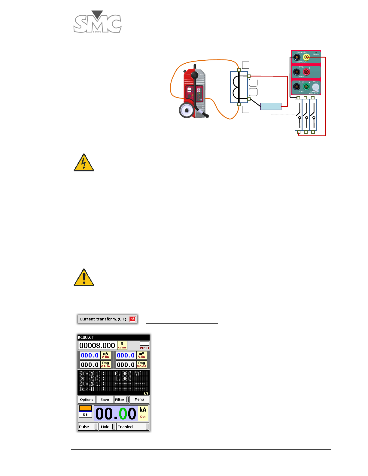
Current Transformer (CT)
Template designed to verify the transformation ratio in
current measurement and/or current protection
transformers (CT).
It is based on injecting current into the CT primary and
measuring the respective current in the CT secondary, thus
calculating the ratio of the transformer being tested. By
measuring the phase angle between primary and
secondary, it is possible to determine its error and its
polarity. With this same template and measuring the
voltage drop in CT secondary bushings, it is also possible
to determine the total burden of the CT in VA at the test
current, in Impedance (Z) and the power factor of the
Page 56

Raptor
56
P1
P2
S2
S1
Burden
burden (cosine phi). The ratio must always be measured at a burden that must be
known, as it varies with this.
Template configuration:
The template is configured as follows:
• Generator: pass-through turn
• Time display: As a timer in seconds (8 s, maximum duration of high current
injection)
• Secondary current meter input A1in in Amps. Auto mode (current in CT
secondary)
• Voltage meter in secondary input V2in in Volts. Auto mode (Voltage drop in
CT bushings)
• Phase angle meter between currents A1in and Io. (Polarity and angle error
of transformer)
• Phase angle meter between voltage measured in V2in and current
measured inA1in (phase angle of burden connected to CT)
• Apparent Power (S) Meter (V2A1) using inputs V2in and A1in, in VA.(Apparent power in burden connected to CT)
• Cosine phi power factor meter (V2A1). (Power factor of the burden
connected to CT)
• Impedance (Z) meter (V2A1) in ohms. (Total impedance Z of burden
connected to CT)
• I0/A1 ratio meter. It presents the reading in terms of Current in
Primary/Current in Secondary. If the theoretic ratio of the CT has been
entered during the configuration of this meter, in terms of nominal primary
current and nominal secondary current, this meter will present the primary
current nominal value entered and the corrected value via the measurement
of the respective nominal secondary current, regardless of what were the
injected and measured currents, thus indicating the ratio error.
Connections:
Connect the output of the pass-through turn
to each side of the CT Primary. The two
bushings of the primary may be indicated as
P1, P2, or in some cases as H1, H2. S1
and S2 correspond to this primary
indication in the first case, and X1 and X2 in
the second case. As a general rule, when
you connect the primary to the pass-through
turn and the secondary to be measured at
the measurement input this must be done as
Page 57

Users Guide
57
shown in the diagram.
With this connection, the phase angle between primary and secondary must be zero or
very close to this value, indicating correct polarity. It is important to connect the voltage
measurement directly to the CT secondary output bushings to include the entire burden of
the CT, and not just part of it, in that measurement. (See diagram)
DANGER – Make
sure that the CT secondary is properly
connected to its receivers. Injecting current into the primary
with an open secondary is very risky both for the CT and for
the operator, as the CT may even explode.
Test:
Select and inject the desired current. The timer will start up. When the countdown
reaches zero, the injection will stop.
If you wish to test another point of the CT, repeat the process at another current value.
When testing a CT, it is usually advisable to test the ratio error and phase angle at
different primary currents, above all if this is a measurement CT. It is advisable to do this
at 120%, 100%, 50% and 20% of its nominal current. If it is a Protection CT it is more
important to test the ratio at the highest possible points permitted by your RAPTOR
system, apart from at 100%.
If you observe that the measurements are unstable, and the values are continuously
changing, use the Filter option to see the most stable values.
If you find the default measurement time established on the Template
(8 s) short and you wish to increase it, do so, but bear in mind the
cable cross-section used (the cable may overheat) and above all, the
overcurrent values and the maximum time supported by the CT being
tested without a risk of damage.
Page 58

Raptor
58
Rogowski CT
Current Sensors or Transducers, based on the so-called
Rogowski coil principle, are being used more and more
frequently today. They are combined with electronics that
condition their output, thus presenting a greater advantage
over the traditional induction CT, in terms of the total
absence of saturation, as they have no magnetic core.
Furthermore, they have secondary voltage, presenting a
ratio that is generally defined as xxx A/ yyy mV or it can
also be frequently seen as xxx mV per Ampere.
The measurement inputs of the devices that use this
technology have high impedance as what they have to
measure is voltage, and their burden is irrelevant. Thus, in general terms, there is no
need to measure it.
Otherwise, it behaves exactly the same as an induction CT, insofar as its ratio precision
and polarity are concerned, and these are the two most important parameters to be
measured, which is what the template does.
Template configuration:
The template is configured as follows:
• Generator: Pass-through turn
• Time display: As timer in seconds (8 s, maximum length of high current
injection)
• V1in input secondary voltage meter in Volts. Auto Mode (voltage in
secondary of Sensor).
• Phase angle meter between voltage V1in and primary current Io. (Polarity
and angle error of Sensor).
Connections:
Connect the output of the pass-through
turn to each side of the Primary of the
Rogowski sensor (or pass the cable
through the center space, where
appropriate). The indication of the
direction of the polarity is inconsistent,
but it is often similar to the classic CTs.
In general, when you connect the
primary to the pass-through turn and
the secondary to be measured in the
voltage measurement input V1 of the
Page 59

Users Guide
59
equipment, follow the steps below:
1. Connect the GREY coloured side of the RAPTOR to the input indicated as
“Incoming current” of the Sensor.
2. Connect the RED coloured side of the RAPTOR to the input indicated as
“Outgoing current” of the Sensor.
3. Connect the RED bushing of measurement input V1* to the secondary
output of the Sensor, indicated as V.
4. Connect the BLACK bushing of measurement input V1* to the secondary
output of the Sensor, indicated as 0.
*The level of the measurement input V1 is very low so a cable with a special connector is
used (supplied with the equipment) to shield the measurements well from possible
electromagnetic noise. In ambients where there is loud noise, the tip of the YELLOW cable
(Earth) must be connected to the earth of the system, or at least to the BLACK tip of the
measurement cable.
With this connection, the phase angle between primary and secondary must be zero or
very close to this value, indicating correct polarity. If the device tested is a direct Rogowski
sensor, not electronically compensated, the standard correct value is 90º.
Test:
Select and inject the desired current. The timer will start up. When the countdown reaches
zero, the injection will stop and the HOLD key will be activated, blocking all the
measurements and ending the test.
If you wish to test another point of the Sensor, repeat the process at another current
value.
When a Sensor is tested, it is usually advisable to test the ratio error and phase angle at
different primary currents to verify linearity.
If the measurements are seen to be unstable, and their values are continuously changing,
use the FILTER option to see the most stable values.
If you find the default measurement time on the Template (8 s) short
and you wish to increase it, do so, but bear in mind the cable crosssection used (the cable may overheat).
Page 60

Raptor
60
Low Power CT
This template is identical to the one described above, so we
refer to that for its use.
Indeed, different systems have appeared on the market to
carry out the same function as a classic CT, but with
advantages over it (economic, size, lack of saturation, etc.)
for certain applications, especially in low voltage.
Different systems are used but, for our application, we are
only interested in knowing what converts the primary current
into a low level voltage, proportional to this current, and
consequently they are tested the same.
However, the linearity and angle acceptance criteria
between primary and secondary may vary depending on the different types of sensor.
AC Resistance
The contact resistance of circuit breaker poles,
sectionalizers, busbar connection points, and cables, etc.
must be verified during any start-up or maintenance of
primary equipment. This resistance is characterised by its
low value, around tenths of micro-ohms. The only way to
measure them is via the 4-wire measurement, which
consists of injecting a current of sufficient value so as to
generate sufficient voltage drop to be measured with
certain accuracy.
Dividing the voltage value obtained by the current value
injected, we obtain the impedance (Z) of the cross-section
between the two points where the voltage measurement
cables are connected.
However, for practical purposes, we are only interested in the real part (resistance R) of
the total impedance, which is the result that we obtain from measuring in Alternating
Current.
To obtain this real part, we must also measure the phase angle. This is the aim of the test
template.
Template configuration:
The template is configured as follows:
• Generator: Pass-through turn
• Time display; As timer in seconds (8 s, maximum length of high current
injection)
Page 61

Users Guide
61
• V1in input secondary voltage meter in Volts. Auto Mode (voltage drop
between the points selected).
• Phase angle meter between voltage V1in and primary current Io.
• Power factor meter (cos phi) between V1 and Io.
• Impedance (Z) meter between the selected points.
• Real part (R) meter between the selected points.
Connections:
Connect the output of the passthrough turn to each side of the point
selected to be measured.
Connect the tips of the test cable of
input V1*, always between the
previous current ones, never outside.
The polarity does not matter.
* The level of the measurement input V1 is very low so a cable with a
special connector is used (supplied with the equipment) to shield the
measurements well from possible electromagnetic noise. In ambients
where there is loud noise, the tip of the YELLOW cable (Earth) must be
connected to the earth of the system, or at least to the BLACK tip of the
measurement cable.
Test:
Select and inject an adequate current value for the test*.
*In general, talking about contact resistances of circuit breakers and sectionalizers or
busbar connection points, currents of around 500 A should be more than safe. In any
case, and whenever possible, try to inject the maximum current that can be obtained
from the system, without overloading the capacity of the point tested. The minimum
current to carry out this test must be over 100 A to be able to obtain reliable results.
The timer will start up. When the countdown reaches zero, the injection will stop and the
HOLD key will be activated, blocking all the measurements and ending the test.
If you find the default measurement time on the Template (8 s) short
and you wish to increase it, do so, but bear in mind the cable crosssection used (the cable may overheat).
Page 62

Raptor
62
Ground grid
This template permits testing the integrity of the grids and
earth taps within a sub-station or power plant.
It is very important to regularly check the integrity of the
ground grid, and above all, of the connections from any
earthed element, as the buried part may have corroded
and this is impossible to detect unless it is done by injecting
current of the highest possible value, so that this
deterioration can really be detected. Being certain of the
correct integrity of the ground/earth system is essential, as if
one of these connections has deteriorated and an earth
fault occurs, it may simply blow just like a fuse would, which
may cause considerable damage to the protected
equipment.
Template configuration:
The template is configured as follows:
• Generator: Pass-through turn
• Time display: As timer in seconds (8 s, maximum length of high current
injection)
• V1in input secondary voltage meter in V. Auto Mode (voltage drop between
the points selected).
Connections:
Connect the pass-through turn(s) to the earth taps selected, where the current injection
will be carried out. In general, one earth tap must be selected as reference and another
as return. For example, the earth tap of the transformer and that of the circuit breaker.
The currents required for this test do not have to be very high, but the cables used must
be long enough to take the current to points that are relatively far away.
The cable cross-section chosen will have to be about 40 or 50 mm, winding 10 turns in
the equipment (C15 configuration at least will always be necessary for this type of tests),
for example, to reach significant distances of around 20 or 25 meters between test
points. Use quite a short cable to wind the turns and connect supplementary cable to
their outputs to reach the required distance.
Place the equipment close to one of the earth taps and extend only one of the ends,
above all the voltage measurement cable.
Connect the tips of the test cable of voltage measurement input V1*, in the tested earth
taps. The polarity does not matter.
Page 63

Users Guide
63
Due to the distance between the two test points, the supplementary measurement cable
that you will have to use for at least one of the test points will be long. To avoid noises,
you must use a shielded cable which shield must be connected to the YELLOW tip of the
equipment test cable.
* The level of the measurement input V1 is very low so a cable with a
special connector is used (supplied with the equipment) to shield the
measurements well from possible electromagnetic noise. In ambients
where there is loud noise, the tip of the YELLOW cable (Earth) must be
connected to the earth of the system, or at least to the BLACK tip of the
measurement cable.
Test:
Select and inject 300 A current. Maintain the current for a few minutes to give time for
any possible fault point to open, if this is the case.
Stop the current injection and test by clicking on the button of the dial.
The voltage measured by the Display V1 must be divided between the meters that
separate the two earth taps to be tested. If the result is more than the value of 0.1 V/m,
this indicates a problem in the ground grid.
If the 300 A current cannot be reached, or it can be exceeded with your configuration,
convert your criterion into V/m that can be reached according to the following formula:
Itest *0.1/300
Carry out this test with the highest possible injected current (always bearing in mind the
capacity of the test cable). Thus it will be closer to the reality of the values that can be
reached in an earth fault.
Page 64

Raptor
64
CT Burden
This template enables us to determine, very accurately, the
burden that is connected in the secondary of a CT.
Accurate knowledge of this value as well as of its power
factor is very important to determine if the CT is suitable or
not for this burden. This information must be used together
with the nominal power of the CT and its magnetisation
curve.
Template configuration:
The template is configured as follows:
• Generator: Auxiliary power output. Current Mode
• Time display: As chronometer in seconds. Stop mode: Push on dial
• A1in input current meter in Amps. Auto Mode (Injected test current).
• V2in input voltage meter in Volts. Auto Mode (voltage required by the
burden).
• Phase angle meter between voltage measured in V2in and the test current
measured in A1in.
• Apparent power (S) meter in VA
• Power factor meter (cos phi) of the burden.
• Impedance (Z) meter of the burden in ohms.
Connections:
The Auxiliary Power Output Generator is used in current mode, not the pass-through turn
generator, to carry out this test, as the current needed to be injected into the burden is the
nominal secondary current of the CT, that is, either 1 A or 5 A.
Warning – It is very important for you to make sure that the passthrough turn gene
rator has no burden of any kind, either by
extracting the cable from the inside, if there is one, or making sure
that the turn is open, with no possibility of accidental closure.
Page 65

Users Guide
65
Burden
P2 P1
S1
S2
For this test to offer you correct results, it
is important not to leave any burden not
measured, so you must proceed to lift
one of the CT secondary physical
connections from the bushing plate of
the actual transformer. Proceed with
caution when carrying out this operation,
making very sure that no primary current
passes through the CT. Although the test
does not require much time, it is very
advisable, after lifting both cables from
the CT bushing plate, to make a bridge
between these bushings with a cable so that, if for any reason the CT receives current in
its primary, its secondary is always short-circuited.
Once the secondary connection cables are available, connect as follows:
1. Connect the BLACK tap of the auxiliary output of the RAPTOR, using a test
cable, to the connection cable of the secondary corresponding to S2. Make
sure that they are firmly connected together.
2. Connect the RED tap of the auxiliary output of the RAPTOR , using a test
cable, directly to the GREEN tap of the current measurement input A1 of the
actual equipment.
3. Connect the BLACK tap of the current measurement input A1 of the
equipment, using a test cable, to the connection cable of the secondary
corresponding to S1. Make sure that they are firmly connected together.
4. Connect the RED tap of the voltage measurement input V2 of the equipment
to the connection cable of the secondary corresponding to S1, making sure
that it is connected downstream from the current injection connection*.
5. Connect the BLACK tap of the voltage measurement input V2 of the
equipment to the connection cable of the secondary corresponding to S2,
making sure that it is connected upstream from the current connection*.
* This is a 4-wire measurement. If you connect the voltage measurement cables
incorrectly, you may include in it the impedance measurement of the actual test
connection, which is not desirable.
Page 66

Raptor
66
Test:
Select and inject the right current value for the test, depending on the nominal secondary
current value of the CT (1 or 5A )
The chronometer will start up and it will be possible to see the test results on the meter
display. When you consider it appropriate, and by clicking on the dial, the injection will
stop, the HOLD key will be activated, blocking all the measurements and ending the test.
As nominal current is being injected, there is no heating risk for the burden or for the test
cables of the equipment.
Voltage-based CT
Sometimes, there are circumstances that prevent carrying
out a ratio test on a CT properly, using current injection.
For example, a CT with very high primary current and
which, due to its location, requires very long connection
cables, thus preventing reaching sufficient current to carry
out a reliable ratio measurement.
Another typical case is that of CTs situated directly in the
high voltage bushings of power transformers, which, in
many cases, do not have an auxiliary primary connection to
allow to directly inject into the CT, so that it is impossible to
inject this current as it would have to pass through the
power windings of the transformer.
In these cases, and as an alternative, this template can be used, thus enabling us to know
the CT turn ratio and its polarity, testing it as if it were a voltage transformer.
This method obviously offers no information about the influence of the magnetic core on
the total accuracy at its precision load.
Template configuration:
The template is configured as follows:
• Generator: Auxiliary power output. Voltage Mode
• Time display: As chronometer in seconds. Stop mode: Push on dial
• V1in input voltage meter in mVolts. Auto Mode (Voltage measurement in
primary of CT).
• V2in input voltage meter in Volts. Auto Mode (voltage measurement in CT
secondary).
• Phase angle meter between voltage measured in V1in and the voltage
measured in V2in. (Primary to secondary phase angle and polarity in
degrees)
Page 67

Users Guide
67
Burden
P2
P1
S1
S2
• V2/V1 ratio meter which is shown as a result of the division between the two
voltages.
Connections:
The Auxiliary Output Power Generator is
used in voltage mode to carry out this
test, feeding the CT secondary, and the
induced voltage is measured in the
primary.
Connect as follows:
1. Connect the BLACK bushing
of the Auxiliary Output to
point S2 of the CT.
2. Connect the RED bushing of
the Auxiliary Output to bushing S1 of the CT.
3. Connect the BLACK bushing of the voltage measurement input V2 to point
S2 of the CT.
4. Connect the RED bushing of the voltage measurement input V2 to point S1
of the CT.
5. Connect point P1 of the CT to the RED tap of the voltage measurement
input V1*.
6. Connect point P2 of the CT to the BLACK tapof the voltage measurement
input V1*.
Warning – It is very important for you to make sure that the pass-
through turn generator has no burden of any kind, either by
extracting the cable from the inside, if there is one, or making sure
that the turn is open, with no possibility of accidental closure.
* The level of the measurement input V1 is very low so a cable with a
special connector is used (supplied with the equipment) to shield the
measurements well from possible electromagnetic noise. In ambients
where there is loud noise, the tip of the YELLOW cable (Earth) must be
connected to the earth of the system, or at least to the BLACK tip of the
measurement cable.
Page 68

Raptor
68
Test:
Select and inject the adequate test voltage level.
It is advisable to inject the maximum voltage value considered to be safe for the
insulation of the secondary winding of the transformer on one side, and that is not going
to exceed the value in primary of 3 V, which is the maximum value that input V1in can
measure.
To determine the maximum injection voltage, the following arithmetic operation must be
carried out:
V of maximum injection = (Nominal primary of CT in A/Nominal secondary of CT in
A)*3
The maximum voltage that can be obtained from the Auxiliary Output of the equipment is
230 V, which should not present any risks for any secondary winding due to insulation.
It will be possible to read the ratio value V2/V1 during the injection, a well as the phase
angle value (polarity), which should be zero or very close to this value.
If the measurements are seen to be unstable, and their values are continuously changing,
use the FILTER option to see the most stable values.
To stop the injection and finish the test, simply click on the button of the dial.
Volt. Transformer (VT)
This template is designed to determine the transformation
ratio in voltage measurement transformers, their
primary/secondary phase angle and their polarity. The
normal denomination of these transformers is usually VT or
also PT, although the latter could be confused with Power
Transformer.
Regardless of their nominal primary value in KV, these
transformers have three standard nominal secondary
values, 100 V, 110 V or 120 V.
This means that their transformation ratios are, as a general
rule, very high; for example, a primary rate VT of 132 KV and secondary of 110V has a
ratio of 1200, which means that if we inject the maximum voltage of the 230 V auxiliary
output through primary, we will obtain a voltage in secondary of 230/ 1200 = 0.192 V,
which can be measured perfectly through measurement input V1.
Page 69

Users Guide
69
Burden
H2
H1
X1
X2
Template configuration:
The template is configured as follows:
• Generator: Auxiliary power output. Voltage Mode
• Time display: As chronometer in seconds. Stop mode: Push on dial
• V1in input voltage meter in mVolts. Auto Mode (Voltage measurement in
secondary of VT).
• V2in input voltage meter in Volts. Auto Mode (voltage measurement in
primary of VT).
• Phase angle meter between voltage measured in V1in and the voltage
measured in V2in. (Secondary to primary phase angle and polarity in
degrees)
• V2/V1 ratio meter which is shown as a result of the division between the two
voltages.
Connections:
The Auxiliary Output Power
Generator is used in
voltage mode to carry out
this test, feeding the VT
primary, and the induced
voltage is measured in the
secondary.
Connect as follows:
1. Connect the RED bushing of the Auxiliary Output to point P1 of the VT.
2. Connect the BLACK bushing of the Auxiliary Output to bushing P2 of the VT.
3. Connect the RED bushing of the voltage measurement input V2 to point P1
of the VT.
4. Connect the BLACK bushing of the voltage measurement input V2 to point
P2 of the VT.
5. Connect point S1 of the VT to the RED bushing of the voltage measurement
input V1*.
6. Connect point S2 of the VT to the BLACK bushing of the voltage
measurement input V1*.
Warning – It is very important for you to make sure that the pass-
through turn generator has no burden of any kind, either by
extracting the cable from the inside, if there is one, or making sure
that the turn is open, with no possibility of accidental closure.
Page 70

Raptor
70
* The level of the measurement input V1 is very low so a cable with a
special connector is used (supplied with the equipment) to shield the
measurements well from possible electromagnetic noise. In ambients
where there is loud noise, the tip of the YELLOW cable (Earth) must be
connected to the earth of the system, or at least to the BLACK tip of the
measurement cable.
Test:
Select and inject the adequate test voltage level.
It is advisable to inject the maximum voltage value that the equipment is able to provide
(230 V) to be at the highest possible point of the nominal primary of the VT.
It will be possible to read the ratio value V2/V1 during the injection, as well as the phase
angle value (polarity), which should be zero or very close to this value*.
If the measurements are seen to be unstable, and their values are continuously changing,
use the FILTER option to see the most stable values.
To stop the injection and finish the test, simply click on the button of the dial.
*The results obtained with this test are exact, but as a very low percentage of Nominal
Primary Voltage of the VT is being injected, the errors that the transformer produces may
be high, both with respect to the ratio and to phase angle. The analysis of where it is or
is not in accordance with what is expected in nominal conditions must be carried out by
the user, bearing this circumstance in mind.
VT Burden
The VTs define their precision class related to a specific
burden called “precision burden”. It is important to know
the real burden that is connected to the VT both in
amplitude and in power factor, and to compare this with the
nominal precision power of VT and thus determine if it is
adequate for the position it occupies.
This template helps measure this burden.
Page 71

Users Guide
71
H2
H1
X1
X2
Burden
Template configuration:
The template is configured as follows:
• Generator: Auxiliary power output. Voltage Mode
• Time display: As chronometer in seconds. Stop mode: Push on dial
• V2in input voltage meter in Volts. Auto Mode (voltage measurement injected
into the burden).
• A1in input current meter in Amps. Auto Mode (Current measurement in
burden).
• Phase angle meter between current measured in A1in and the voltage
measured in V2in. (Burden phase angle and polarity in degrees)
• V2/V1 ratio meter which is shown as a result of the division between the two
voltages.
• Apparent power (S) meter in VA
• Power factor meter (cos phi) of the burden.
• Impedance (Z) meter of the burden in ohms.
Connections:
The Auxiliary Output Power
Generator is used in voltage
mode to carry out this test,
feeding the burden connected
to the secondary burden of the
VT and measuring the current it
consumes.
The connection cables must be
disconnected from the VT
secondary, taking the appropriate precautions, thus insulating this secondary. The
injection of the test voltage will be carried out on these cables.
Connect as follows:
1. Remove connection from secondary X1
2. Connect the BLACK bushing of the Auxiliary Output to the cable that was
connected at point X2 of the VT.
3. Connect the RED bushing of the Auxiliary Output to the GREEN bushing of
the current measurement input A1.
4. Connect the BLACK bushing of the current measurement input A1 to the
cable that was connected at point X1 of the VT.
5. Connect the RED bushing of the voltage measurement input V2 to the cable
that was connected at point X1 of the VT.
Page 72

Raptor
72
6. Connect the BLACK bushing of the voltage measurement input V2 to the
cable that is connected at point X2 of the VT.
Warning – It is very important for you to make sure that the pass-
through turn generator has no burden of any kind, either by
extracting the cable from the inside, if there is one, or making sure
that the turn is open, with no possibility of accidental closure.
Test:
Select and inject the adequate test voltage level.
The voltage that must be selected is the one that corresponds to nominal secondary of
the VT. With very rare exceptions, this will be 100 V, 110 V or 120V. The template uses
the voltage value measured through input V2 for all its calculations, but this
measurement may not be identical to the selected injection value, as the auxiliary power
output is regulated in the primary winding of the internal output transformer of the
equipment. Consequently, and depending on the burden value, a small error may occur
at its real output, due to the fact that we are connecting it in the secondary. If you wish to
exactly inject the nominal value, adjust the selection with the dial until you read this
nominal value on the relative meter.
You will be able to read all the values indicated by the meters during the injection.
If the measurements are seen to be unstable, and their values are continuously changing,
use the FILTER option to see the most stable values.
To stop the injection and finish the test, simply click on the button of the dial.
Short-circuited PT
This template is designed to carry out short-circuited
impedance tests in any Power (PT) or Distribution
Transformer.
This test provides a lot of information about the state of the
internal geometry of the PT, detecting possible movements
of the internal windings due to transport or to a very severe
fault, by comparing the results obtained in each winding.
These must be reasonably balanced.
The Short-circuited Voltage percentage (Vcc%) or the same
percentage defined in Impedance (Z%) may also be
calculated. These are the two ways in which this
information can appear on the technical characteristics plate of the PT. The definition of
the Short-circuited voltage is:
Page 73

Users Guide
73
H2 H1
X1
X2
Voltage expressed in % of the nominal primary voltage (High), necessary to obtain the
nominal primary current of the transformer, with the secondary side (Low) short-circuited.
Several tests are required, one per winding, on the one hand, to calculate these
parameters, as well as an adequate calculation later on, using the results obtained in
each one of them, and also considering the nominal technical characteristics of the PT
(which are on the transformer plate) with respect to transformation ratio, connection
group, short-circuit impedance (or voltage) in % of nominal, nominal primary voltage or
High winding, and nominal secondary voltage or Low winding.
Template configuration:
The template is configured as follows:
• Generator: Auxiliary power output. Voltage Mode
• Time display: As chronometer in seconds. Stop mode: Push on dial
• V2in input voltage meter in Volts. Auto Mode (voltage measurement injected
into High winding).
• A1in input current meter in Amps. Auto Mode (Current measurement in
High winding, in this case short-circuited).
• Phase angle meter between current measured in A1in and the voltage
measured in V2in. (Phase angle between short-circuited current and injected
voltage).
• Power factor meter (cos phi) of the short-circuited transformer.
• Impedance (Z) meter of the short-circuited transformer in ohms.
• Reactive component meter of Z (X) in ohms.
• Real component meter of Z (R) in ohms.
Connections:
The Auxiliary Output Power Generator is used in voltage mode to carry out this test,
feeding between two phases of the High side of the PT and measuring the current it
consumes.
The bushings corresponding to
the two phases that are injected
are short-circuited in the LOW
side of the PT. It is very important
for the connection cables and
devices to the PT bushings to
have a large cross-section, as
very high currents can be
produced in the short-circuit.
Page 74

Raptor
74
Connect as follows (the connection between phases H1 and H2 is described, repeat this
connection for phases H2H3 and for H3H1:
1. Connect the BLACK bushing of the Auxiliary Output to H2 of the PT.
2. Connect the RED bushing of the Auxiliary Output to the GREEN bushing of
the current measurement input A1.
3. Connect the BLACK bushing of the current measurement input A1 to H1 of
the PT.
4. Connect the RED bushing of the voltage measurement input V2 to H1 of the
PT.
5. Connect the BLACK bushing of the voltage measurement input V2 to H2 ot
the PT.
6. Short-circuit the bushings the Low side of the PT, X1 and X2, with adequate
cables.
Warning – It is very important for you to make sure that the pass-
through turn generator has no burden of any kind, either by
extracting the cable from the inside, if there is one, or making sure
that the turn is open, with no possibility of accidental closure.
Test:
First of all, you must calculate the equivalent value at reduced voltage of the nominal
current of the PT. Use the following formula:
Pn/Vn=Inom of the PT
Where: Pn is the Nominal Power of the PT in KVA, Vn is the nominal primary voltage in
KV of the PT and Inom is the nominal current of the PT in Amperes.
Now calculate the value of the Short-circuited voltage:
(Vn * Vcc%/100)*1000 = Vcc in volts.
Where: Vn is the nominal primary voltage in KV of the PT, Vcc% is the value on
characteristics plate of the short-circuited impedance in %.
Calculate the respective value of reduced voltage according to availability of equipment
(9 A and 230 V max) in permanent:
Vccr = Vcc * Ired/Inom
Where: Vcc is the short-circuited voltage in Volts, Inom is the nominal current of the
transformer in Amperes and Ired is the reduced current that is going to be used, which
must be less or equal to 9 A (permanent max. of the auxiliary output of the equipment).
Start by setting a value at Ired of 9 A.
Page 75

Users Guide
75
The Vccr value obtained must be lower than the available in the equipment , 230 V. If it
is higher, replace Ired of the formula with a lower value until the Vccr value is less than
230 V.
Once you know these values, connect the equipment output and gently adjust the output
voltage until you obtain the value READ on display V2, equal to Vccr. If the real shortcircuited impedance coincides with the theoretic impedance, you should be reading a
current value on display A1 that is very similar to Ired.
You will be able to read all the values indicated by the meters during the injection.
If the measurements are seen to be unstable, and their values are continuously changing,
use the FILTER option to see the most stable values.
To stop the injection and finish the test, simply click on the button of the dial.
Save the results with a comment, indicating that this is the measurement H1H2 and
repeat the process with the remaining phase loops.
PT ratio
This template permits measuring the voltage ratio between
the primary or High winding and the relative secondary or
Low winding of a Power (PT) or Distribution Transformer.
However, unless the transformer is single-phase or threephase with connection group YNyn…, this voltage ratio will
not coincide with the transformation ratio that appears on
the characteristics plate of the PT.
To convert the voltage ratio measured at this transformation
ratio, several calculations are required, as well as the
execution of tests with different connections to the PT. These
calculations and connections depend on the PT group, and
as there are many different ones, they are not described in this Handbook, and are left to
the discretion of the equipment operator.
If this calculation method is required, please contact us and we will give it to you.
Template configuration:
The template is configured as follows:
• Generator: Auxiliary power output. Voltage Mode
• Time display: As chronometer in seconds. Stop mode: Push on dial
• V2in input voltage meter in Volts. Auto Mode (voltage measurement injected
into Low voltage winding).
• Voltage ratio meter Vo/V2
Page 76

Raptor
76
N H1
X1
n
Connections:
The Auxiliary Output Power
Generator is used in voltage
mode to carry out this test,
feeding between two phases or
between phase and neutral, as
possible, the High side of the
PT.
The relative voltage is
measured between the two
bushings of the PT
corresponding to the same phases on the Low side, which are being injected from the
High side.
DANGER – Make sure that you are connecting the Auxiliary
Generator of the equipment to the High side. Never connect
it on the Low side, because very dangerous voltages may
occur on the High side, if this happens.
In general, and assuming that a PT with neutral accessible in both windings is being
tested, connect as follows:
1. Connect the BLACK bushing of the auxiliary equipment of the equipment to
bushing N of the High side of the PT.
2. Connect the RED bushing of the auxiliary equipment of the equipment to
bushing H1 of the High side of the PT.
3. Connect bushing n of the Low side of the PT to the BLACK bushing of the
V2in measurement input of the equipment.
4. Connect bushing X1 of the Low side of the PT to the RED bushing of the
V2in measurement input of the equipment.
If the PT is three-phase, you must carry out a measurement in each phase. If the neutral is
not accessible in either of the two windings, you must inject between two phases (H1H2)
and measure on the Low side in agreement with the calculation and connection diagram
required, depending on the PT connection group.
Warning – It is very important for you to make sure that the pass-
through turn generator has no burden of any kind, either by
extracting the cable from the inside, if there is one, or making sure
that the turn is open, with no possibility of accidental closure.
Page 77

Users Guide
77
Test:
Connect the equipment output and gently adjust the output voltage until it is as high as
possible (max. 230 V).
You will be able to read all the values indicated by the meters during the injection.
If the measurements are seen to be unstable, and their values are continuously changing,
use the FILTER option to see the most stable values.
To stop the injection and finish the test, simply click on the button of the dial.
Save the results with a comment, indicating that this is the measurement H1N/X1n, or the
couple of phases you are using, and repeat the process with the remaining phase loops.
Page 78

Raptor
78
SPECIAL FUNCTIONS
The templates described above only generate a suitable configuration for a certain test.
Apart from giving a configuration, the functions also carry out more complicated tests
where the generation or stoppage values vary with time in a totally automated process.
To access the functions:
It has two functions: Recloser and CT Magnetisation.
Recloser.
This function is designed to verify, in a very simple manner, the
correct operation of an integrated RECLOSER; that is, a device
that include the MV circuit breaker, the protection CTs, the protection relay with recloser
function and the total control of the system. These devices are found more and more
frequently in Medium Voltage Distribution circuits.
The results shown include trip time and reclosing time (dead time) of each one of the
reclosing cycles that the device actually carries out.
It does not require any type of configuration by the operator, although he must take into
account that the maximum time this test lasts is set, by default, at 8 seconds. This time
should be sufficient for the majority of the cases, but the operator must decide if it should
be longer or shorter, editing it if required. The function will be left with the last length of
time assigned. If you wish, you can configure the test for it to end by binary input or by
intervention of the operator, instead of by time.
The trip times are represented as T and the reclose times as R.
Page 79

Users Guide
79
Function configuration:
Connections
Connect the output of the Pass-through Turn Generator to the input and output of the
Circuit Breaker of the recloser. This can be done in one single pole or in the three poles
connected together in series.
Test:
Set a higher output current value than the trip set value in the over current element of the
protection integrated into the recloser, to ensure that it trips. After that, the function
automatically detects the trips and the reclosing times due to the appearance and
disappearance of current in the generator circuit, and the automatic opening and
reclosing process must be continuously carried out by the device being tested.
The device keeps the function running until the maximum test time has elapsed (8 s by
default) or the manual stop condition has been fulfilled (by default this is by pushbutton),
if the relay has completed the number of retries that have been set.
It is recommendable to use the generation current measurement range that adapts better
to the current level that is going to be injected.
Number of
total trips
Time elapsed
from the first
trip to the last.
Time of last
trip
Fault current value
Area where the
opening and closing
times are shown.
Page 80

Raptor
80
CT Magnetisation
This function permits the application of an increasing voltage in
the secondary, with the primary open, until the current
transformer is saturated, showing the knee point. Whilst the process is being carried out,
the current and voltage values are measured. As soon as the knee point is detected (in
agreement with a certain criterion), it is displayed.
Knowing the knee point is very important in all CTs, whether they are measurement or
protection CTs, but especially in the latter as if there is a fault in the system, the primary
current increases a great deal more than the nominal current, and it is essential for the
CT to be able to produce the necessary voltage in its secondary bushings to maintain the
consistency of its transformation ratio, so that the protection devices receive real
information about what is occurring on the primary side. As the CT burden remains
constant (although there are protection devices with saturable inputs whose impedance
varies with the current) and the current increases a great deal, the voltage required to
maintain the ratio also rises a great deal above that defined in its nominal power.
There are different Standards to define the knee point. As usual, there is an IEC standard,
commonly used all over the world, and the ANSI standard* that even contains two
definitions of knee point. In any case, the three standards define very similar value points.
This function uses the IEC criterion to calculate and show the Knee point. This criterion is
defined as: “Point at which a 10% increase in voltage over the previous value causes a
50% increase in current over the previous value”
* The ANSI Standard is divided into two, the ANSI 30º and the ANSI 45º, and the criterion is defined
as "Point at which, on a graphical representation of I, logarithmic type on both axes, the slope of the
tangent at the point reaches a value of 30º or of 45º depending on the Standard applied".
Page 81

Users Guide
81
Function configuration
This is shown on the image below:
Connections
All the connection are made in the secondary winding (1 or 5 A) of the CT. The Primary
winding must be left OPEN.
Connect the BLACK bushing of the Auxiliary Generator of the equipment to the bushing
of the secondary of the CT, marked S1.
Connect the RED bushing of the Auxiliary Generator of the equipment to the GREEN
bushing of the current measurement input A1in.
Connect the BLACK bushing of the current measurement input A1in to the bushing of the
secondary of the CT marked S2.
Connect bushing S1 of the CT to the BLACK bushing of the voltage measurement input
V2in.
Connect bushing S2 of the CT to the RED bushing of the voltage measurement input
V2in.
Test
The function is automatic, so the operator only has to enter the maximum I and
maximum V values into the relative controls, and simply click on the dial to start the test.
If the knee point is found, this will be displayed on the screen. Do not interrupt the test as
it has not finished. Always let the demagnetisation process end.
The maximum voltage value entered is especially important. If you enter a very high value
with respect to the value that would really correspond to the CT tested, the knee point will
Maximum current
permitted to
carry out the test.
Maximum voltage to
carry out the test.
Process display and
knee point.
Magnetisation graph
display
Page 82

Raptor
82
be obtained, but with little resolution as the function calculates up to 40 increases with
respect to the value entered (they could be too big). It would also be possible for it to be
above the knee point with the first increase and then the test would not offer any result. If
the value entered is smaller than the real value of the CT, it would not offer any result,
either. It is advisable to enter a slightly higher value than expected in this parameter, if
this is known. The level curve in V generated is not linear with time. Increases in V
decrease as it approaches Vmax. This improves the resolution in the area of interest.
The test consists of injecting a ramp of ascending voltage values up to 20% above the
maximum voltage entered or a maximum of 40 pitches (logarithmic voltage increases).
After the maximum test value has been reached, the CT is demagnetised, generating the
same voltage points, in descending order and with a smaller time interval.
During the test, the injected voltage will increase every 2 seconds up to a maximum of
20% above the maximum value entered.
The test ends with a demagnetisation process, if the current measured or voltage
measured exceeds the maximums entered, or the maximum voltage that the equipment
can generate is reached.
The test can also be aborted by pressing (off). In this case, the CT is NOT demagnetised.
When the test ends, by tapping on the
Graph
button, it is possible to see the graph of the
test points that make up the magnetisation curve and the position of the knee point, if it
has been detected. The representation of the reference axes of the curve is logarithmic for
the X-axis (I magnetisation), and linear for the Y-axis (V magnetisation).
Page 83

Users Guide
83
I NEED MORE CURRENT, VOLTAGE or POWER
One of the most frequent questions is the current limit that users can obtain from the
system over a certain burden. This is especially frequent when the user wishes to exceed
the nominal current of the test equipment or he is trying to use long cables to carry high
current.
As you know, to obtain high current, the maximum output voltage possible from the
injector equipment is required as well as the minimum load impedance possible.
Maximum output voltage of the system
The power supply
One of the most common errors is not to pay the necessary attention to the power supply
of the system.
Bear in mind the maximum admissible consumption for each unit:
Raptor-MS: 19 A in permanent, 38 A for 3 minutes and 74 A for 3 seconds.
Raptor-SL: 26 A in permanent, 52 A for 3 minutes and 104 A for 3 seconds.
The feed cables supplied with each unit are adequately dimensioned for these
consumptions. The part that you have to pay attention to is the cable that takes the power
supply to the system. You must add up all the consumptions foreseen for each unit and
dimension it so that 4.5 A/mm
2
are not exceeded in permanent regime. Although with
this current density calculated for the permanent, it is correct to use the system in 3 min.
and 3 s. regimes, if you wish to optimise the output voltage in the other regimes (3 min, 3
s) set the cable to the same density.
Recommended cross-sections for each conductor (in mm2) for the feed cable of the entire
system:
System Permanent 3 minutes 3 seconds
C-05 4 10 16
C-15 10 16 35
C-25 16 35 50
C-35 25 50 70
You must bear in mind that the Raptor gives its maximum power with a 240 Vac supply,
measured at the start of the feed cable supplied. Insofar as this voltage is less or if it
drops during the test, the maximum current or maximum voltage will also drop.
If you supply the system with a Generator and this has regulation, try to set it a little
higher (for example at 250) to try to compensate the drop that will occur at the time of
injection. Take care not to exceed the equipment specification at any time (230 + 10%).
Page 84

Raptor
84
If you are not sure about the possible reaction of the generator regulation on removing
burden, do not follow this recommendation.
Number of turns.
In traditional primary injection equipment, you must adapt to the different output ranges.
If you choose one with greater voltage, you will have less current or vice-versa. The same
occurs in the Raptor system, but with the number of turns. If you wind 2 turns you will
have double the voltage and half the current; if you wind 3, you will have triple the
voltage and a third of the current. The difference is that in the Raptor system, the number
of output ranges is much greater, enabling you to adapt more to the voltage/current
need.
Thus, the best adaptation will always be achieved when you can wind the maximum
number of turns, for the required current and time.
Number of Raptor-SL units
The Raptor-SL slave units do not determine the maximum current that the system can
handle, but they do provide voltage for the pass-through winding. Each unit will increase
the available power by 5KVA in permanent regime, which is the equivalent to
approximately between 0.6 and 1.3V per turn (depending on the regime). When you
wish to work with high currents/power, the best solution is to add these units to the
system.
Minimum load impedance
This is the other factor that attention must be paid to when maximising the available
power/current. Normally, in tests with high currents, the limitation is determined by the
connections used to join the injection system to the burden to be tested, as the latter,
apart from being fixed, is negligible.
Distance to burden.
The circuit impedance (both the resistive part and the inductive part) is directly
proportional to the distance that exists between the burden and the injection system. Try
to shorten this distance as much as possible. Sometimes it is more advisable to have
several shorter cables than one long one. In this way you will not be forced to user longer
ones than necessary. You can always place them in series for greater distances or place
them in parallel to increase the cross-section.
Due to the modular construction of the Raptor system and to the reduced weight of each
unit, sometimes it is more practical to raise the units close to the burden, for example, on
a forklift truck, than coping with the weight and cross-section of the cables.
The cross-section of the secondary conductor.
In order to minimise the resistance of the injection circuit, it is recommended to use the
largest secondary cross-section possible, when you are optimising the power / current.
The hole diameter for the pass-through winding of the Raptor system is optimised for the
current density to be low.
Page 85

Users Guide
85
On the other hand, you must know that copper, like almost all materials, increases its
resistivity with temperature, being able to increase the resistance of the circuit up to 5%
with the subsequent drop in available power. It is therefore advisable, when this factor is
decisive to obtain the current, for you to leave the cables to cool down.
The minimum cross-section recommended for the secondary winding is 4mm2 / A for the
permanent regime, 8mm2/A for 3 minute and 16mm2/A for 3s.
Parasitic inductance.
It is common to find that operators worry considerably about the resistance of the circuit
but they forget about the inductance, which, as you know, is vectorially added to obtain
the impedance. Well, this reactance, after dealing with the issue of the cross-section, is
what has the greatest influence on not being able to reach the necessary current values.
The only action you can carry out to improve (decrease) the inductance is to care for
geometry of the path. The area covered by the turn left by the outgoing conductor with
the return conductor must be reduced to a minimum, reducing to a minimum the area of
the turns, if any, wound around the raptor system to configure the secondary.
Join the cables of both sides with insulating tape or with clamps, and keep them joined
together, to reduce the space between them as much as possible, along their entire
length. Interlace the outgoing cables with the return ones is one of the best tactics.
To reduce to a minimum the parasitic inductance generated when configuring the passthrough winding with the Raptor system, it is recommendable to acquire high current
ultra-flexible cables, supplied by SMC, as optional elements, measuring 3, 6 and 9 m
long.
Page 86

Raptor
86
Page 87

Users Guide
87
CONFIGURATION AND MAINTENANCE
Configuration
Access the menu:
Change language
Change date and time of the system
Adjust Internet connection properties (TCP/IP)
At times, such as to update your system or to control it from
the PC (useful for remote support or courses), you must
connect the Raptor-HH console to the Internet. Certain
parameters must be adjusted for the communication to be
correct.
DHCP mode is active by default, meaning that the IP address
of the Ethernet adaptor will be configured automatically, when
you switch on the equipment after connecting the mains cable. This system will only work
correctly when there is a DHCP Server in your network. Consult with your network
administrator to see if this exists. For this reason, the manual configuration panel is
disabled, as shown on the previous image.
If there is no DHCP Server in your network or you are going
to connect directly to a PC, you must set the parameters of
the console network adaptor by hand.
To manually establish the addresses and mask, deactivate
the DHCP option.
Page 88

Raptor
88
If you are going to connect the console to a network without DHCP Server, you must ask
the administrator to give you these four parameters. You can copy the last three (Net
mask, Gateway and DNS Server) from any computer that you have connected to the
network. The IP address no. This must be exclusive in the network.
If you want to connect the console directly to a PC (only for VNC use), proceed as
follows:
• Open the properties of the PC network card and take note of the four
parameters shown on the figure.
• Copy the last three (Net mask, Gateway and DNS Server) into your device.
• In the IP address, put the same first three groups as those of the PC and in
the fourth group, put any number except for that of the PC.
• Save the configuration.
If the Internet parameters are not configured on your PC, you must
enter them by hand IP:192.168.1.1 / Net Mask:255.255.255.0
Gateway:0.0.0.0 DNS Server:0.0.0.0
In some cases, the direct connection to the PC does not work, even
after having correctly configured the parameters. In this case, try
with a crossed Ethernet cable or inserting a switch.
VNC Server
This permits showing/controlling the Raptor-HH device from
the screen of a local or remote computer. This is useful, if, at
any time, you want your equipment to be directly controlled from SMC to make any kind
of adjustment, to clear up doubts or receive training.
Before trying to use this function, you must correctly configure the
Internet connection properties.
To establish the connection, a VNC client application is started up on the computer from
where you are going to make the connection. We will use the
TightVNC viewer
client, a
free application available from page:
http://www.tightvnc.com/download/1.3.10/tightvnc-1.3.10_x86_viewer.zip.
After starting up the VNC client, you must
select the
listen
mode, pressing the
“Listening mode” button, as the connection
is started by the Raptor-HH VNC server.
You do not have to indicate anything in the
“VNC server” field.
Page 89

Users Guide
89
You must now start up the Raptor-HH VNC server. Press the VNC Server button on the
configuration menu to access the following screen:
If you want to contact SMC for remote support, write the remote address: “eurosmc.es”
or press Default host. If, on the contrary, you wish to contact a PC on your local network
or your own PC, you must enter its IP address.
If you are going to connect with SMC, you must wait until you are
told you can press the Connect button.
If you have decided to connect to a PC of your network, a window will appear on this PC
like the one shown below after pressing Connect:
You will now see an exact copy of your Raptor-HH
screen. You may even press on the keys and execute
certain controls.
Default host.
PC address in
listening mode.
Establish
connection.
Page 90

Raptor
90
Keep the system up-to-date
Access the maintenance menu
From this menu you can
access different options that
will help you keep your system
up-to-date. Among the possible options:
• Update control program of the Raptor-HH unit.
• Update firmware of the Raptor-MS unit.
• Consult the Firmware versions of the Raptor-SL
units.
• Consult serial numbers of the units that make up the system.
• Adjust the Hardware meters (this requires password).
Update control program of the Raptor-HH/M.
Every now and again, SMC
publishes updates on its
Internet servers of the control
program of the Raptor-HH and Raptor-MS units, which
corrects problems detected, introduces improvements or
adds functions. You can access these updates when you
wish. You can see which version of the console software
you have on the actual button.
The only way to exit this menu is by pressing Restart.
If you have not already done
so, you must adjust the TCP/IP
parameters as indicated in the “Configure the Internet
connection parameters” section with the
TCP/IP
button.
When you press the
Update
button, the download and
updating process will start. If
the version that exists in the
SMC server coincides with the
one you have in your console,
a window will appear indicating
this. Otherwise, it will continue
with the process. Press
Restart
when it finishes.
Whenever you update the console, an update of the Master
unit will be downloaded at the same time. The next time you
have a Raptor-HH unit connected to a Raptor-MS unit, and
after restarting, it will automatically proceed to verify that
both versions are the same. If these do not coincide, the
program will take you to the “Update firmware of the Raptor-MS” screen.
Page 91

Users Guide
91
Update firmware of the Raptor-MS unit.
You must always update the
Raptor-MS unit after you have
updated the Raptor-HH unit. You do not have to do it
immediately, but the system will force you to do so before
start working with this unit.
A window will appear like the one on the right. Press
Re-
save
Consult the Firmware versions of the Raptor-SL unit.
With this option, you can know which version of the firmware
exists in the Raptor-SL units.
Consult serial numbers of the units that make up the system.
This enables you to see the serial numbers of all the units that
make up the system.
Adjust the Hardware meters
This permits modifying the setting of both the internal and the
Hardware meters. This option requires a password to be
provided by SMC.
Caution – This maintenance option must only be used by people
with advanced knowledge of the Raptor. Any modification of the
parameters of these settings will affect the performance
of the
equipment.
Page 92

Raptor
92
The screen is shown below:
Exit
. This closes the meter adjustment window and returns to the maintenance window.
Default values.
This assigns the default values to all the meters in all the ranges, not to
the one selected.
Adjustment.
This starts the adjustment process of the selected meter. Once you start to
adjust the meter, you must finish the process, at least in one range, if you have several,
because if you abort, it will be saved with incorrect values. You are only allowed to exit
the adjustment process when you finish a complete range or, if the meter only has one
range, when the entre process has been completed. The adjustment process is guided
through an assistant and only requires following the steps indicated.
Selection area of
meter to be adjusted
Proceed to
adjust
Default
values
Close meter
adjustment screen
Page 93

Users Guide
93
PROBLEMS THAT MIGHT ARISE
Page 94

Raptor
94
SPECIFICATIONS
Raptor-MS
Raptor-MS master unit
(values @240 Vac, 50 Hz, 1 sec. turn 960 mm2, measured 25 cm on each side)
HIGH CURRENT OUTPUT
Output Current Output Voltage
No Load V (0%Imax) 0-1,20 Vac - Continuous
3,8 KAac (25%Imax) 0-0,81 Vac - Continuous
7,5 KAac (50%Imax) 0-0,42 Vac - 3 min
9,5 KAac (63%Imax) 0-0,22 Vac - 3 s
No Load Resolution 25 uVac
Output Frequency 20-400 Hz
(Power reduction applied at 50 < f > 60 Hz)
LOW CURRENT OUTPUT
(Not simultaneous with high current output)
Output Current 0-35 Aac (0 – 9 Aac continuous)
Voltage Output 0-200 Vac
Output Frequency 20-400 Hz
(Power reduction applied at 50 < f > 60 Hz)
Isolated output yes
Protection fuse
MEASUREMENTS Secondary Current
(for high current output)
Ranges 0-1 / 0-15 KAac
Resolution 1 Aac, 10 Aac
Accuracy ±0,2% of the value ±0,2% of the range
Phase angle
±0,25°
Ammeter/Low Level Voltmeter
Amm. Ranges 0-0,2 /0-2/0-20 Aac
• Amm.Resolution
0,1 mAac, 1 mAac, 10 mAac
Amm. Impedance <10 mΩ
Volt. Ranges 0-30 mVac,0- 0,3 Vac, 0- 3 Vac
Volt. Resolution 0,015 mVac, 0,15 mVac, 1,5 mVac
Volt. Impedance >3000 KΩ
Frequency range 20-400 Hz
Accuracy ±0,1% of the value ±0,1% of the range
Phase angle
±0,25°
Isolated input yes
Voltmeter
Ranges 0-0,2/0-2/0-20/0-300 Vac
Resolution 0,1 mVac, 1 mVac, 10 mVac, 0,15 Vac
Impedance >120 KΩ
Frequency range 20-400 Hz
Page 95

Users Guide
95
Accuracy ±0,1% of the value ±0,1% of the range
Phase angle
±0,25°
Isolated input yes
Binary Input
Type Dry contact/Voltage
Voltage mode Levels 1,5 V , 15 V
Time resolution 1 ms
Max. Voltage 250 Vac
Isolated input yes
COMMUNICATIONS
2 RS-485 Raptor Bus connectors to control unit Raptor-HH
and/or other units
2 IrDA interfaces Two channels for master/slaves linking
GENERAL
Supply 230 ±10%, 50/60 Hz
Weight 35 kg
Protections Protected by miniature circuit breaker
Sec. hole diameter 85 mm
Transport Wheels, folding handle, fixed handle
Page 96

Raptor
96
Raptor-SL
Raptor-SL slave unit
(values @240 Vac, 50 Hz, 1 sec.turn 960 mm2, measured 25 cm on each side)
HIGH CURRENT OUTPUT
Output Current Output Voltage
No Load V (0%Imax) 0, 0.79 or 1.59 Vac - Continuous
3,8 KAac (25%Imax) 0, 0.67 or 1.34 Vac - Continuous
7,5 KAac (50%Imax) 0, 0.55 or 1.11 Vac - 3 min
15 KAac (100%Imax) 0, 0.30 or 0.61 Vac – 3 s
COMMUNICATIONS
2 IrDA interfaces Two channels for master/slaves linking
GENERAL
Supply 230 ±10%, 50/60 Hz
Weight 35 kg
Protections Protected by miniature circuit breaker
Sec. hole diameter 85 mm
Transport Wheels, folding handle, fixed handle
Page 97

Users Guide
97
Raptor-HH
Raptor-HH Hand Held Console
CONTROL
Display Transflective high definition color TFT with resistive Touch
Panel, 54x71 mm (5,7”)
Wheel Rotary Encoder (Wheel and click)
LEDs Alarm, Connectivity, Power
COMMUNICATIONS
RS-485 Raptor BUS Communication with Raptor-MS
USB Connection to PC (RaptorSync)
RJ-45 Ethernet for software updates
Mini-PC powered by Windows CE
GENERAL
Power Supply Self-powered from Raptor-MS, or with external power
adapter 5 Vdc
Weight 0,4 Kg
Dimensions 110 x 185 x 35 mm
Case High quality injection-moulded ABS, strong and ergonomic
design, edge surfaces protected with TPE non-slip material
Compliance
The instrument is intended for use in high-voltage
substations and industrial environments.
All EuroSMC products have conformity to CE-marking
directives, complies with IEC and international standards,
and are designed and manufactured in accordance with the
requirements of the ISO-9001 Quality Standard
Transport Bag Nylon soft bag
Connection cable 5 m cable, 8 mm
Page 98

Raptor
98
Ordering Information
ORDERING INFORMATION
SYSTEM CONFIGURATION
Raptor C05 1 x Raptor-HH + 1 x Raptor-MS
Raptor C15 1 x Raptor-HH + 1 x Raptor-MS + 1 x Raptor-SL
Raptor C25 1 x Raptor-HH + 1 x Raptor-MS + 2 x Raptor-SL
Raptor C35 1 x Raptor-HH + 1 x Raptor-MS + 3 x Raptor-SL
ACCESSORIES INCLUDED
Raptor-HH Hand held console with software
Stylus
Nylon Bag
System cable
USB cable
Ethernet cable
Power adapter
User’s Manual
Raptor-MS Raptor master unit
Power supply cord
Low signal voltmeter cable
Calibration certificate
Nylon protective bag
Raptor-SL Raptor slave unit
Power supply cord
Nylon protective bag
OPTIONAL ACCESSORIES
CBL3M-RAP 120 mm2 cross section and 3 meters (9 ft) long
CBL6M-RAP 120 mm2 cross section and 6 meters (18 ft) long
CBL9M-RAP 120 mm2 cross section and 9 meters (27 ft) long
RAP- ACC1 Up to 4 CBL cables can be connected
RAP- ACC2 Up to 6 CBL cables can be connected
 Loading...