

Page 1

SF6 6100 Pump Back Analyser
Instruction Manual
SMC
5840 S. Memorial Drive
Suite 208
Tulsa, Oklahoma
74145
Tel. 918-622-5725
Fax. 918-664-2073
sales@noramsmc.com
Page 2
Warnings
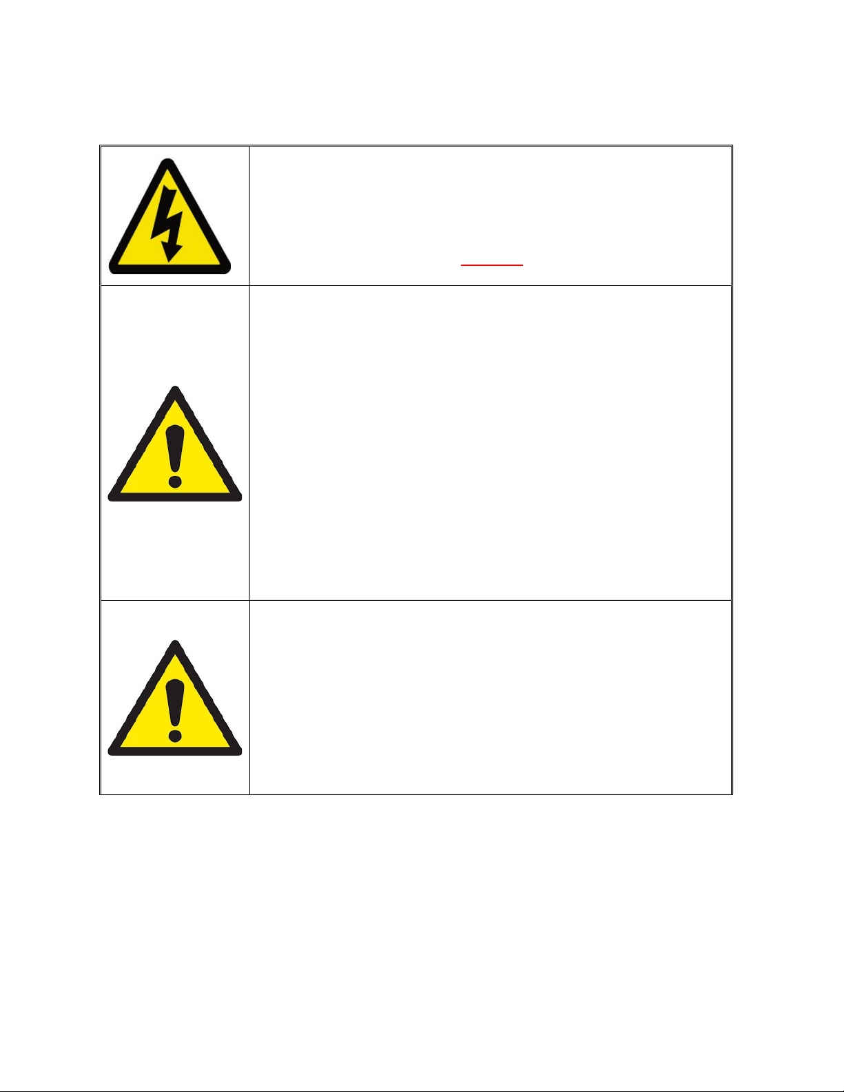
Electrical Shock Hazard
Do NOT remove internal metal panel
There are no user-serviceable parts in this unit
Do not attempt to repair the analyser yourself
Refer all servicing to qualified personnel
The unit should not be exposed to extreme temperatures
< -5°C or > +50°C (< +23°F or > +122°F)
Normal operating temperature is +5°C to +35°C (+41°F
or +95°F)
Do not operate the unit with the carry case lid closed
Avoid direct sunlight exposure
Do not use liquid cleaners, aerosols or solvents to clean
the case
Use a damp cloth for cleaning with the power cable
disconnected
Do not use this equipment near water
Only use fingers to touch and operate the display panel
Make sure any ventilation slots and the fan on the side
panel are free of obstruction
This unit is NOT designed for use in life support
No responsibility can be held for injury or loss of life
Always use a tube connected to the gas outlet (4) which
situations or any use that is not specified by the
manufacturer.
caused by inappropriate use of this equipment.
is vented to atmosphere when working with gases that
may by toxic or injurious.
Page 3
Warnings
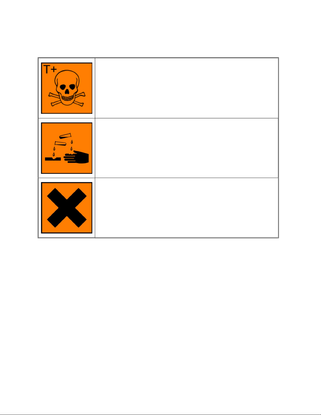
HF & SO2 are toxic and can be fatal if inhaled
HF & SO2 cause severe skin burns
HF causes severe damage to the eyes
H2S & CO are toxic and can be fatal if inhaled
Read the MSDS sheets carefully before working with
these toxic gases
HF and SO2 are extremely corrosive to the respiratory
tract
Read the MSDS sheets carefully before working with
these corrosive gases
H2S and CO are extremely flammable in high
concentrations
Long term exposure to CO causes organ damage
SO2, HF and H2S are harmful irritants to the eyes, skin
and respiratory tract even in small doses
Very toxic to aquatic life
Contents
1 Introduction ........................................................................................................................................... 4
2 Technical Specification ...................................................................................................................... 5
3 Analyser Description .......................................................................................................................... 7
4 Getting Started ...................................................................................................................................... 8
4.1 Battery Charging .......................................................................................................................... 8
4.2 Advisory Screens ......................................................................................................................... 9
5 Performing a Test ............................................................................................................................. 10
5.1 Main Screen Display ................................................................................................................ 10
5.2 Setting the Test Parameters ................................................................................................. 10
5.3 Preparing the Analyser ........................................................................................................... 11
5.4 Sampling ....................................................................................................................................... 13
5.5 Results and Finishing .............................................................................................................. 14
5.6 Notes about Dewpoint Measurements ............................................................................. 15
6 Operational Description ................................................................................................................. 17
6.1 Main Screen................................................................................................................................. 17
6.2 Live Graph Display ................................................................................................................... 18
6.3 Line Purge Option ..................................................................................................................... 18
Page 4

6.4 Pump Back Option .................................................................................................................... 20
6.5 Start Delay ................................................................................................................................... 21
6.6 Working with Pre-Loaded Test Parameters .................................................................. 22
6.7 Working with SF6 and N2 mixtures .................................................................................... 23
6.8 Working with SF6 and Air mixtures................................................................................... 24
6.9 Working with SF6 and CF4 mixtures .................................................................................. 25
7 Rapidox Menu System .................................................................................................................... 27
7.1 Calibrate ....................................................................................................................................... 27
7.2 Data-Logging .............................................................................................................................. 31
7.3 Auto Abort ................................................................................................................................... 34
7.4 Sampling Modes ........................................................................................................................ 35
7.5 Timed Mode ................................................................................................................................ 36
7.6 Continuous Mode ...................................................................................................................... 38
7.7 Set Units ....................................................................................................................................... 39
7.8 Date & Time ................................................................................................................................ 39
7.9 Passwords ................................................................................................................................... 40
8 Options Menu System ..................................................................................................................... 43
8.1 Data Transfer ............................................................................................................................. 43
8.2 System Control .......................................................................................................................... 47
8.3 Gas Cylinder Testing ................................................................................................................ 48
8.4 Auto N2 System Clean .............................................................................................................. 49
8.5 Language ...................................................................................................................................... 49
8.6 Screen Colour ............................................................................................................................. 50
8.7 Screen Brightness ..................................................................................................................... 51
8.8 Diagnostics .................................................................................................................................. 51
8.9 Restore .......................................................................................................................................... 52
8.10 About ......................................................................................................................................... 52
9 Troubleshooting ................................................................................................................................ 53
10 Warranty .............................................................................................................................................. 56
10.1 Conditions of Warranty: .................................................................................................... 56
1 Introduction
The Rapidox SF6 6100 Pump Back is a battery-powered “zero emission” SF6 multigas
analyser capable of measuring multiple gases simultaneously in a rugged and portable case.
Depending on the configuration the analyser can measure up to eight parameters including
sulphur hexafluoride (0-100% SF6), sulfur dioxide (0-100ppm* SO2), dew-point (60/20°Cdp H2O), carbon tetrafluomethane (20-80% CF4), hydrogen fluoride (0-10ppm HF),
air (0-100%), carbon monoxide (0-100ppm) and hydrogen sulphide (0-100ppm). In
addition, the SF6 compartment gas pressure is displayed on-screen as well as some other
selectable parameters.
* 0-500ppm is available on request
Page 5

The sample gas can be used if the inlet pressure is between 0.3 bar and 10.0 bar.
The analyser has a full pump back facility allowing any gas stored inside the analyser to be
re-pressurised and returned to the SF6 compartment. The sample hose and storage bag can
be vacuum purged before testing to ensure no mixing of contaminated gas occurs. During
the testing cycle no SF6 can escape into the atmosphere.
The sampled gas is stored inside a special flexible bag held within the analyser. This bag
inflates and deflates during the testing cycle and can be used to store any SF6 that is not to
be pumped back afterwards. The bag is constructed from a material that is highly resistant
to moisture or air penetration. Various safety features are in place to prevent the bag from
over-filling during use.
The analyser has a built-in PC and all functions are accessed via a 7” touch screen panel.
The analyser is fully automatic and will run in various sampling modes where sample gas is
drawn into the analyser via a special FEP-lined sample hose and DILO couplings. The gases
pass through the various sensors and data is processed and displayed on the screen. The
analyser is fitted with a printer, alarms, data-logging functions and USB output.
The portability of the analyser is achieved by means of two lithium battery packs (one for
the main operation and one for the pump back) which can be charged on any worldwide
mains power. The unit will run for up to eight hours on the battery before recharging is
required. The unit will also run directly on mains power while the battery is recharging.
Up to twenty pump back cycles can be performed on a single charge.
2 Technical Specification
Rapidox SF6 6100 Pump Back Analyser
Mains Voltage for charging 90-260Vac 50/60 Hz
Main Lithium Battery Operation
Pump back Lithium
Battery Operation
Analyser dimension 570mm (w) X 470mm (d) X 280mm (h)
Weight 21 kg without accessories
Gas Storage Bag 5 Litres capacity at sea level
Sample Time 8 minutes
Display 7” full colour PC touch screen
Up to 8 hours on a single charge
5-7 hours to fully charge from flat
Up to 20 pump back cycles on a single charge
(depending on the final gas pressure)
5-7 hours to fully charge from flat
Page 6

Warm up time 15 minutes at 20°C
Temperature -10°C to 40oC
Normal operating conditions
Minimum Gas Inlet Pressure 0.3 bar
Maximum Gas Inlet Pressure 10 bar
Maximum Pump Back Pressure 10.5 bar
Data Output Via USB memory stick or thermal printer
Sampling Timed or Continuous modes
SF6 Sensor (infra red)
SO2 Sensor (electrochemical)
H2O Sensor (polymer)
CF4 Sensor (balance)
HF Sensor (electrochemical)
Air (electrochemical O2 sensor) or N2
(balance)
CO & H2S Sensor (electrochemical)
Calibration
Data-logging
Fuse 1 (main PC) T3.15A H250V 20mm anti surge
Fuse 2 (compressor) T16A H250V 20mm anti surge
Humidity 10 to 90% RH
Pressure 800 to 1100 mbar absolute.
0-100% scale
+/- 0.5% full scale accuracy
0-100ppm (or 0-500ppm) scale
+/- 2% full scale accuracy
-60 to +20°Cdp
+/- 2°Cdp of reading accuracy
Optional display corrected to 20°C available
>20 <80% scale
calculated as a balance gas
0-10ppm scale
+/-2% full scale accuracy
0-100% scale
+/-2% full scale accuracy
0-1000ppm scale
+/- 2% full scale accuracy
Calibration by the user using zero and span gases.
Not H2O sensor*
Continuous on-board data-logging downloadable via
USB
Page 7
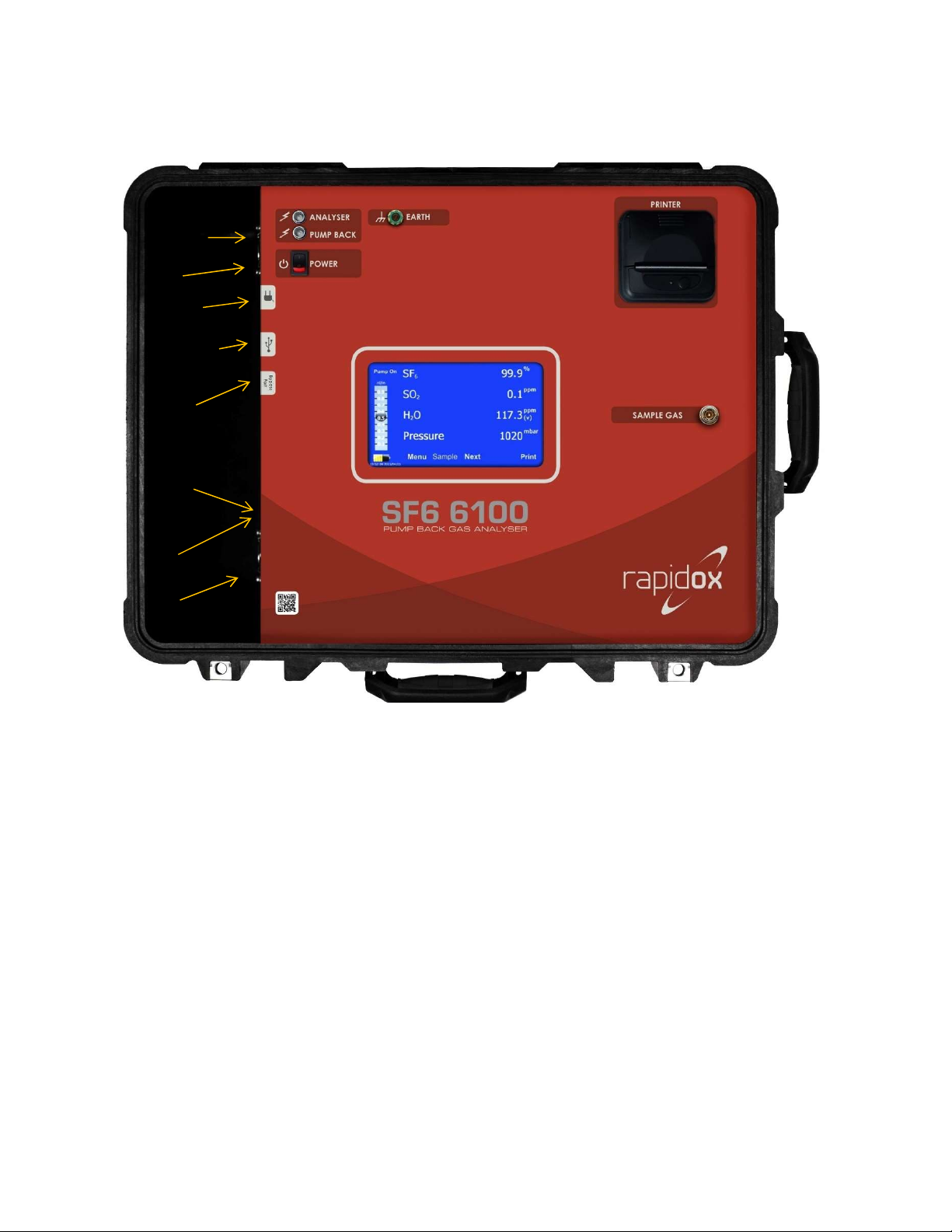
3 Analyser Description
1
2
4
3
6
7
8
9
10
5
11
12
13
1
4
1
5
Figure1: Layout of the SF6 6100 Pump Back Analyser
1. Main display and touch screen menu system
2. Thermal printer
3. Sample gas inlet (via closed coupled fitting)
4. Earth fixing point
5. Gas flow indicator on the display
6. Power on/off switch
7. LED battery charging lights
8. USB memory stick port
9. Fuse holders (see Table 1)
10. Mains inlet
11. 18V charging point (using special vehicle charging adapter)
12. Service Connection Point
13. Ventilation Slot
14. Cooling Fan
15. Bypass Port
Page 8

4 Getting Started
The two labelled fuses will be removed for transportation safety reasons. There are two
fuses located in fuse holders labelled with the values listed in Table 1. This completely
isolates the lithium batteries. These fuses are different and must not be mixed up. The
fuses should be inserted into the correct holders (9) and fixed into position before first use.
Remove the fuses temporarily if you are transporting the analyser by air. If you require the
analyser to be earthed during operation, please connect your earth lead to the earth fixing
point (4).
Open the Peli-case fully and switch on the Rapidox using the switch (6). The analyser
screen will boot up and the display will show readings from the sensors after
approximately sixty seconds.
Note that if the analyser was previously being used in “Continuous” mode, then the
warning picture shown in Figure 2 number 5 will be displayed on the screen during boot
up. This is to remind you that the gas is free flowing out of the bypass port, and a separate
gas recovery system should be attached.
4.1 Battery Charging
The analyser can run on battery OR mains power. When on mains power and the battery is
charging the LEDs (7) will show a red colour. This will eventually turn orange and finally
green when the unit is fully charged. There is an on-screen battery life meter which shows
the remaining battery life and indicates if the unit is charging or not. It takes between five
and seven hours to fully charge a flat battery depending on operational circumstances.
To charge the battery, attach the IEC mains lead to the mains socket on the side of the
analyser (10). Alternatively, an optional vehicle charger can be used with the 18V charging
point (11). Note that you must leave the lid open when on charge as the cooling fan will
operate to vent the battery compartment.
Lithium batteries need to be charged carefully and the analyser is fitted with various safety
features to make sure the batteries do not over heat during a charge. The temperature of
the batteries is measured and should it exceed safe limits the charger circuit will disable
itself. The LED will flash slowly to indicate it is too hot to charge. This may occur if the unit
is used in very hot countries. Please place the unit in a cool location such as an air
conditioned office to charge correctly.
When the unit is running on battery power the LCD indicators (7) remain switched off until
the mains lead is re-connected.
Page 9
compartment)
detached
separate gas recovery system
deactivated
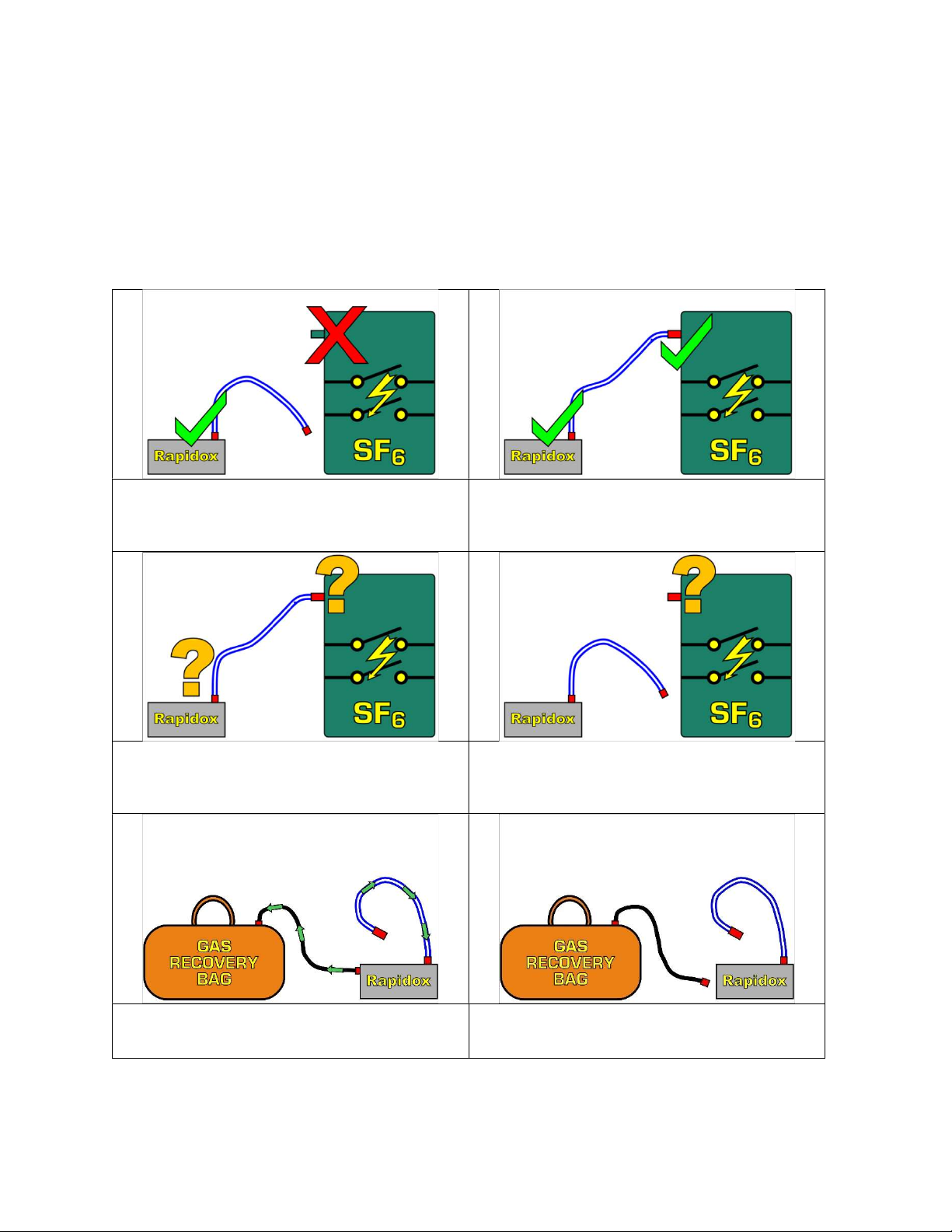
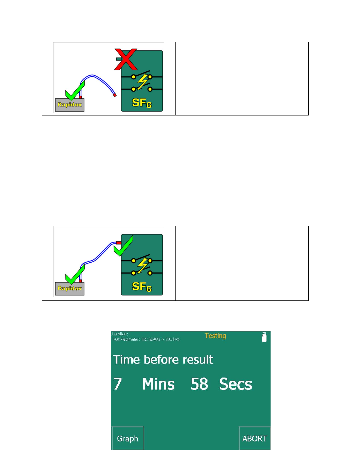
4.2 Advisory Screens
During sampling, line purge and pump back the analyser checks to see if the sample line
hose is correctly fitted to ensure that the cycle works correctly and doesn’t allow any
contamination of the compartment gas with air, or any SF6 is allowed to escape into the
atmosphere. Various simple instructions are displayed on-screen to make it easy to follow
the correct sequence. These are as follows:
1) Shows how to correctly set up the analyser
for a line purge (line must be connected to
the Rapidox but NOT to the gas
3) Questions if the sample line doesn’t appear
to be connected to anything that has gas
pressure i.e. the sample line has become
2) Shows that the Rapidox sample line should
be connected to the pressurised gas
compartment ready to take a sample
4) Questions if the operator has disconnected
the sample hose from the gas compartment
before attempting a line purge
5) Analyser is running in continuous mode so
the bypass outlet should be connected to a
6) Asks for the external gas recovery system to
be disconnected once continuous mode is
Page 10
5 Performing a Test
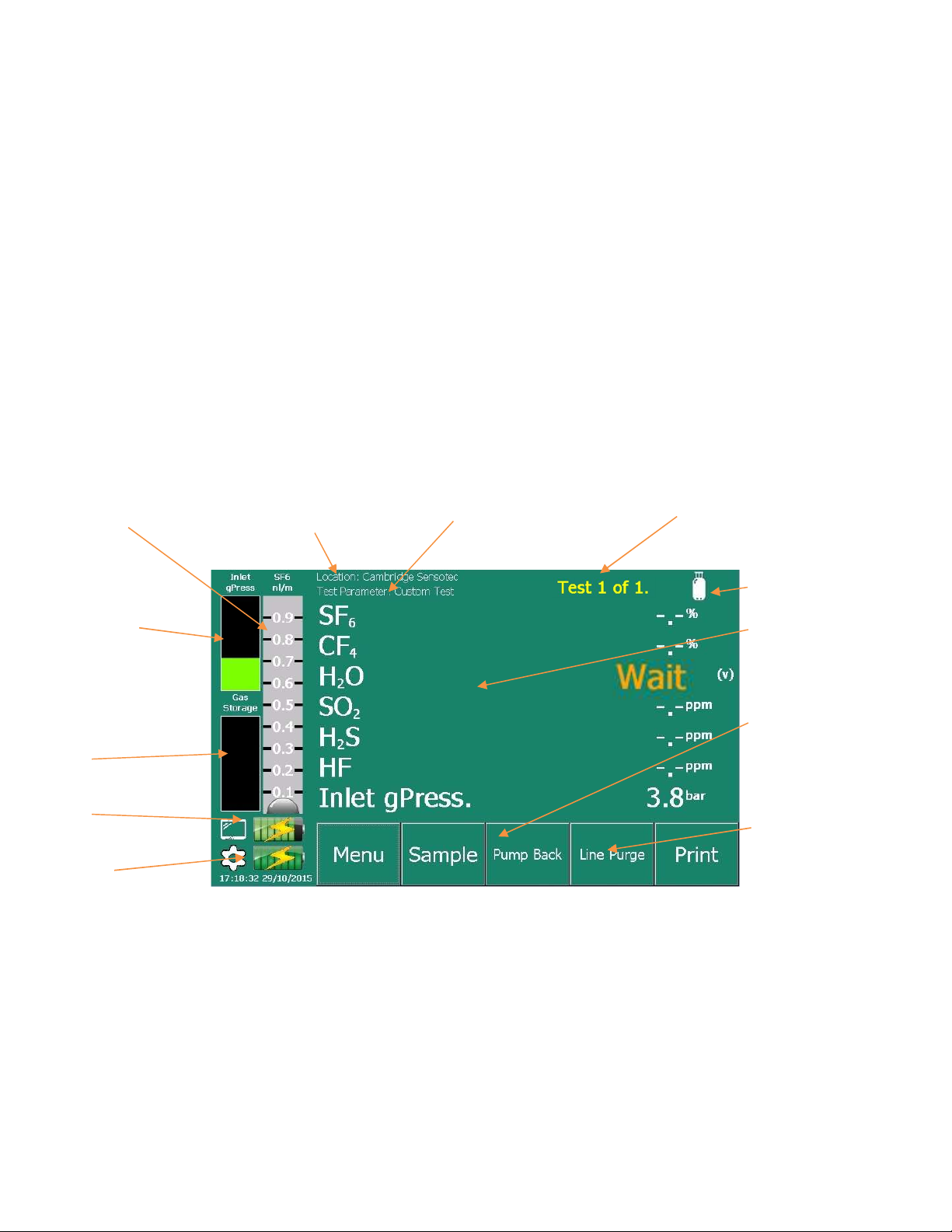
Tap on the
gas
of
Analyser Status
Gas inlet pr
essure
meter
Icon for using “Gas
See section
8.3
With the analyser switched on and ready, use this guide to prepare the machine for testing
and complete an analysis. All screens and menus are soft keys so to change or access
anything you gently press the screen with your fingertips. Pressing over the name of a gas
will open a live graph screen (see 6.2) showing the progress of the sample over time.
5.1 Main Screen Display
Flow Gauge
Indicator
Figure 2: Examples of different on-screen help messages you may encounter during operation. The screen
message includes text prompts explaining what action to perform.
User Editable
Test Location
User Editable IEC / CIGRE
Test Parameter
Message
Bottle” mode
Gas Storage Bag
Capacity
Battery Status
Analyser
Battery Status
Pump Back
5.2 Setting the Test Parameters
Timed tests are fixed at 8 minutes long to complete the testing correctly without filling the
bag to capacity. To set this option press MENU – SAMPLING and enter these parameters as
shown in Figure 4. Full details of this menu option are in section 7.4.
interest to produce
a live time graph
(6.2)
See section 6.4 for a
full description of
how to perform a
Pump-Back cycle
See Section 6.3 for a
full description of
how to Line Purge
Figure 3: Main screen just after boot up. The H2O sensor is still warming up which takes approximately 60
seconds. Note that not all sensors may be present in your equipment
Page 11

Figure 4: Use this option to change the sampling method to “Timed” or “continuous” and set the sampling
duration and other options.
An initial set up is recommended as follows (see 7.4 for full details):
1) Measurement Mode: Set this to TIMED.
2) Sample Duration: This is fixed to 8 minutes and the option is greyed out
3) Start Delay: Set this to 0 unless you must walk away from the equipment before a
test starts. Please see section 6.5 for details on this function.
4) Line Purge: Set this to MANUAL.
5) Pump Back: Set this to AUTO if you are measuring gas from an in-service
switchgear or circuit breaker.
6) Print Results: Set this to AUTO so the printer will produce a report at the end of
the test.
7) Number of Tests: Set this to 1.
8) Location: If you want to name the location EDIT it now and it will be saved with
the results.
9) Test Parameter: Please refer to section 6.6 for details on this feature.
10) SF6 / CF4 mix in use: Only change this to YES if you are working with CF4 blends
otherwise leave it as NO. Selecting the wrong option will make the results
inaccurate. Please see section 6.9 for details on this function*
11) Make sure you press SET to save your choices.
*note that this feature will only be visible if it was specified at the time of order.
5.3 Preparing the Analyser
Page 12
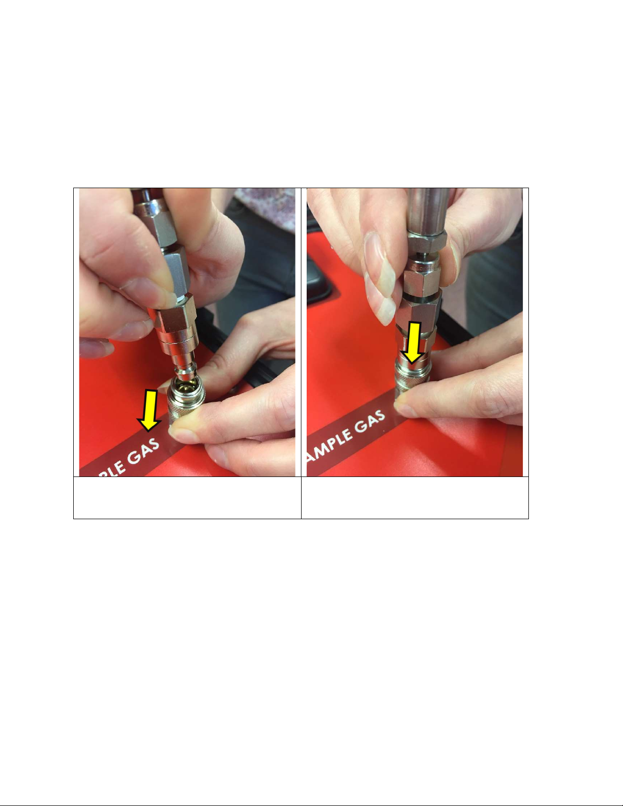
Make sure that the sample line hose is clean and dry. A brand new 2m long sample hose is
supplied pre-pressurised with dry SF
at 5bar pressure. Take the male end of the hose and
6
insert it into the Sample Gas Inlet as shown in Figure 5. Do NOT attach the other end to
anything yet. Use both hands to pull the knurled collar of the inlet coupling downwards as
you push the male fitting into place.
Release the collar to lock in position. To release the coupling simply pull down on the
knurled collar and the hose will self-eject.
Pull the knurled collar down with your finger tips
before trying to attach the male hose fitting. Line up
the hose fitting before attempting to connect
Figure 5: Correct procedure for attaching the sampling hose to the analyser.
Push male coupling into the female firmly whilst
holding the collar down. Release the collar only
when fully engaged
As this is the first test it is recommended to perform a vacuum purge of the sample hose by
pressing the button labelled “Line Purge”. This will vacuum out any unwanted air from the
system and takes approximately 45 seconds to complete. You will see on-screen message
(see Figure 6) to remind you NOT to connect to the gas compartment. Once completed the
following message will show:
Page 13
Connect the Rapidox sample hose to
the analyser but NOT the gas
compartment
Figure 6: Screen message displayed when attempting a line purge.
5.4 Sampling
Once the line purge is completed press SAMPLE to begin the test. You will be instructed
(see Figure 7) to connect the female coupling on the end of the hose to the gas
compartment using a DILO male coupling adapter (supplied).
Gas
compartment
pressure is OK
Connect the Rapidox sample hose to
the gas compartment to pressurise
the analyser with sample gas
Figure 7: Screen message displayed when performing a sample analysis.
Page 14
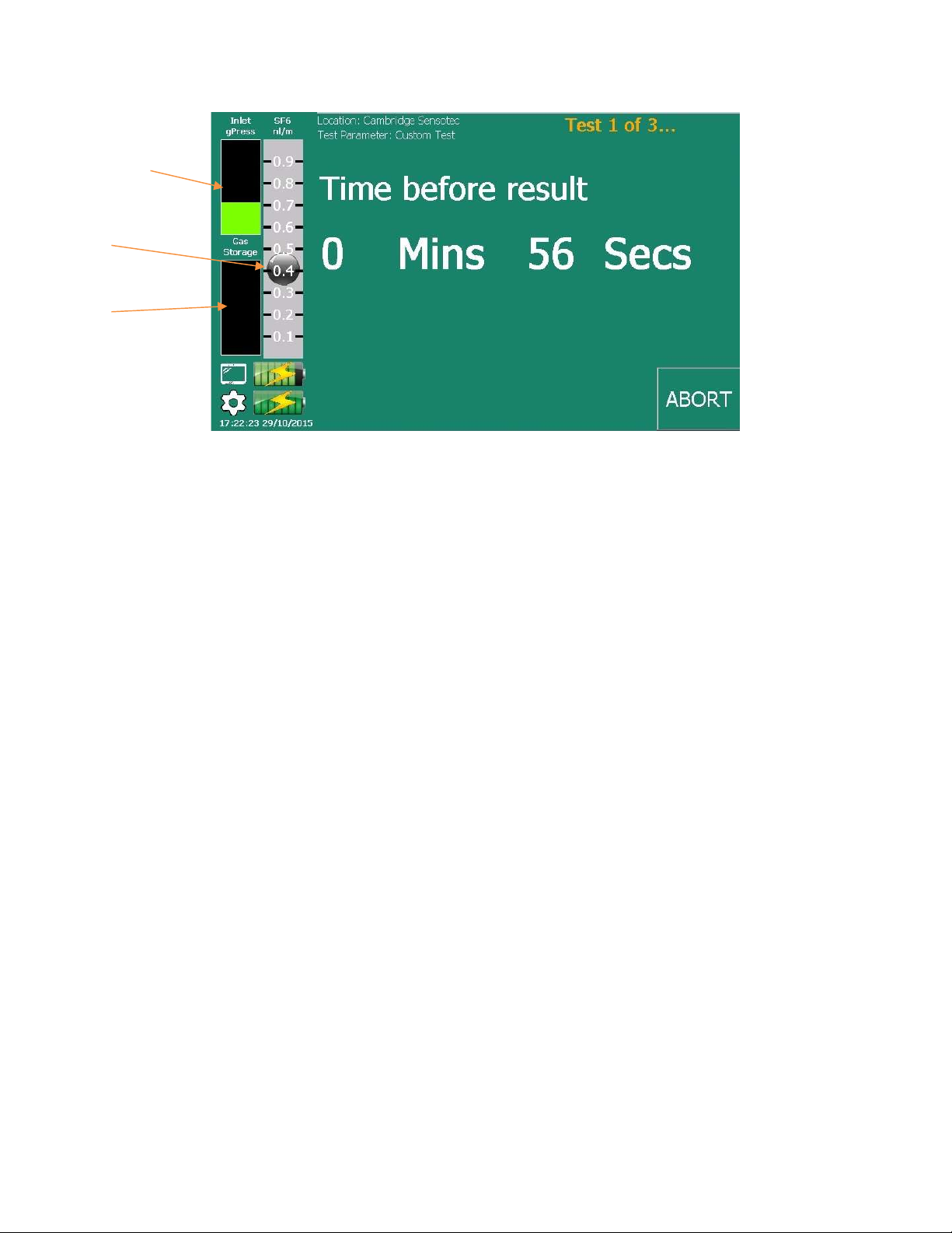
Sample gas is
flowing
Storage bag is
empty
Figure 8: Screen message displayed when performing a Timed analysis. The test will take eight minutes to
Once the hose is correctly connected you will see the Gas Inlet Pressure Meter (see Figure
8) rise and the pressure display will indicate the gas compartment pressure. Note that
there must be a minimum pressure of 0.5bar to proceed. If the pressure is acceptable the
gauge will appear green. Press OK to continue.
A timer will appear on the screen and count down eight minutes. During this period the
SF6 gas will flow into the analyser at a rate of 0.5L.min-1. The black ball on the electronic
flow gauge will rise and settle in the mid-point (see Figure 8). Press “Graph” to see a live
display of the readings and “Abort” to cancel the test.
If at any time during the test, large amounts of toxic gases are detected and “Auto Abort” is
enabled then the test will stop mid-way with an advisory warning.
When the test is completed the results of the analysis will display on the screen and the
printer will produce a short summary report. If pump back is set to “Auto” the unit will
immediately begin pumping the gas back to the compartment.
complete.
5.5 Results and Finishing
With the test completed and all the gas pumped back the analyser storage bag will be
empty and the machine is ready for the next test. If multiple tests were selected, then the
cycle will repeat itself until everything is completed. Finally, the screen will indicate to the
user that it is safe to disconnect the hose from the gas compartment and then from the
Rapidox before moving on to the next location.
Note that if a sequence of repeated tests is performed it is not usually necessary to do a line
purge each time, as the hose is full of dry SF6 from the previous test.
Page 15

Note that if you are testing very small volume circuit breakers at low pressures then it is
NOT recommended to do repeated testing as continual sampling and pumping back can
eventually make a noticeable change in the gas quality; particularly the overall moisture
content.
The following flow chart in Figure 9 shows the complete operational sequence for
performing a gas sample test with the Rapidox Pump Back Analyser.
5.6 Notes about Dewpoint Measurements
The dewpoint sensor fitted to this equipment is a special high speed polymeric type
designed for use in SF6. For optimal readings dewpoint is measured at compartment
pressure and the readings are then pressure corrected to atmospheric pressure
1013mbara.
The sensor itself is electronically “cleaned” regularly by the analyser to prevent
contamination building up and causing a drift of readings. At the start of each timed test
the sensor is cleaned. This takes approximately two minutes to complete and an additional
four minutes is then required to allow the readings to settle. In exceptional circumstances
the sensor will perform an advanced clean which takes up to six minutes to complete.
During this time no readings are visible on the plot or recorded in the data logger. The
logger will record the words “Clean” or “Adv. Clean” instead.
If the analyser is operated in continuous mode, then the cleaning will happen automatically
every thirty minutes. The initial clean cycle will begin five minutes after the analyser is
powered on. During any clean cycle the continuous mode will display “Please Wait” on the
main screen which will disappear once the cleaning is complete.
The dewpoint reading displayed on the screen shows the units as °Cdp but this is calculated
as frost point when readings are below 0°C. Although there is no actual frost generated on
a capacitive sensor surface, the readings are calculated as frost point so direct comparisons
can be made with a chilled mirror analyser. This is important because the difference
between “over ice” and “over water” calculations become significant in very dry
measurements. All CIGRE and IEC test standards are in terms of frost point “over ice”
regardless of the measurement method.
As well as recording the absolute dewpoint at room temperature it is possible to display an
equivalent dewpoint corrected for temperature at 20°C This options features in the Units
menu and the unit can be accessed by tapping on the main screen over the displayed unit.
Tap the screen with your finger to change from “°Cdp@RT” to “°Cdp@20°C”.
Page 16
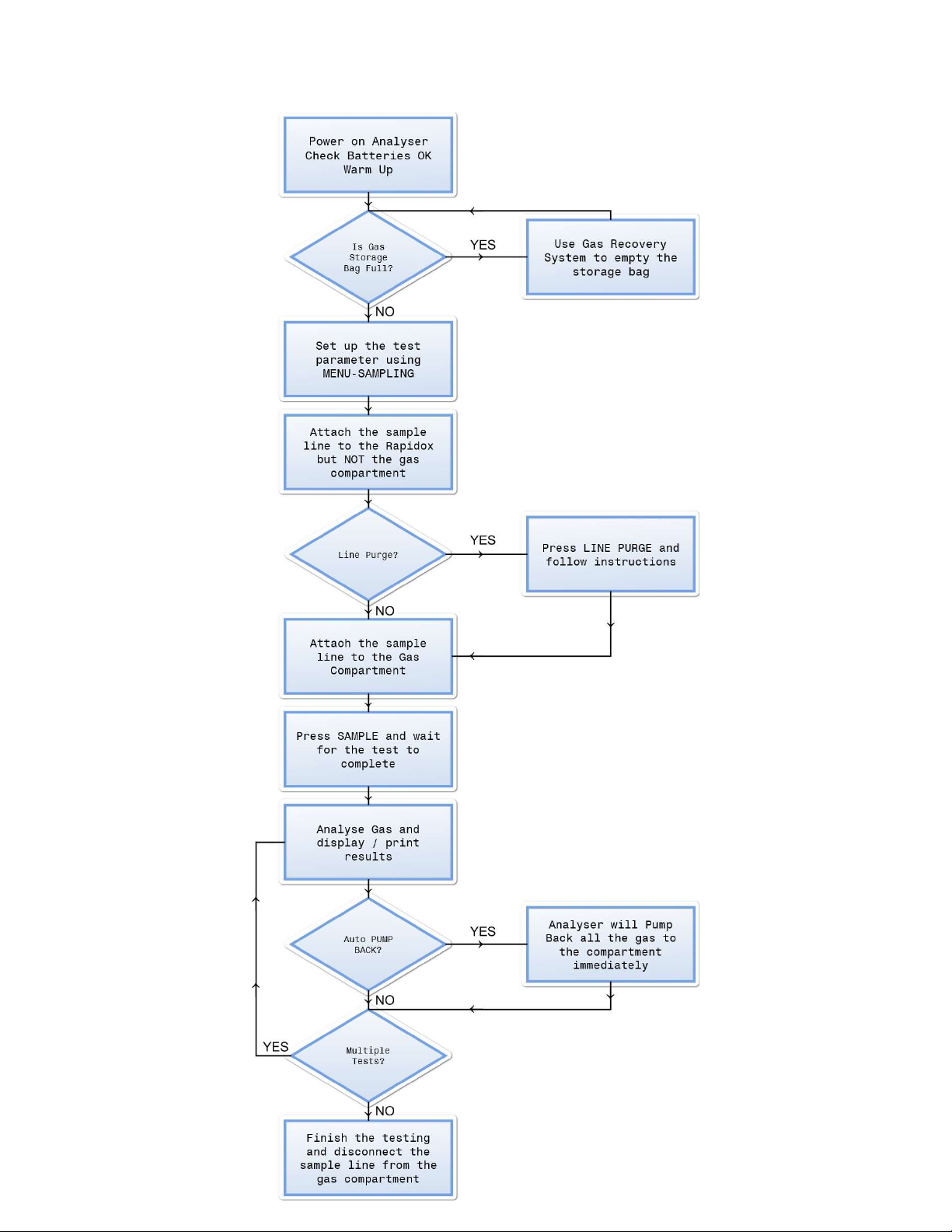
Figure 9: Operational Flow Chart
Page 17
6 Operational Description
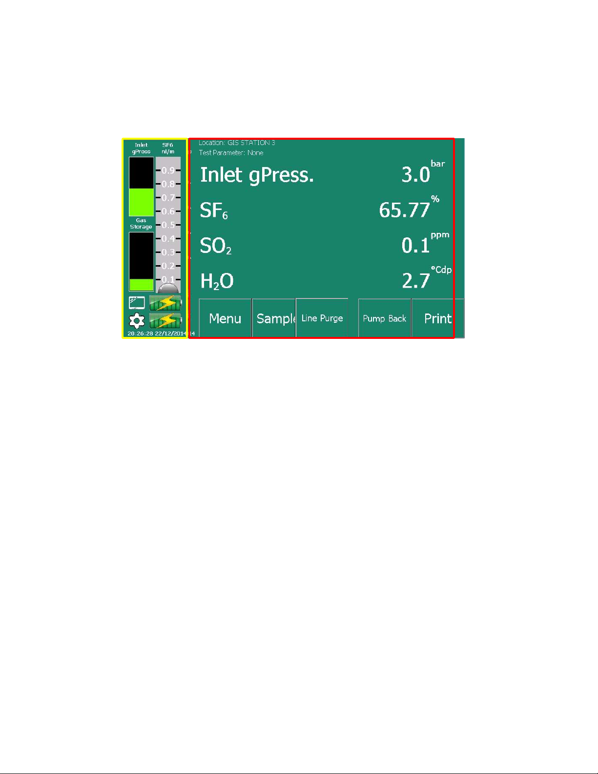
6.1 Main Screen
Figure 10: Main operation screen (RED) configured with just three sensors, showing sensor readings with
side panel (YELLOW) indicating the gas flow, bag, battery and pressure status
During sampling the target gas flow is factory set to 0.5L.min-1 and this is displayed on the
side panel using the electronic gauge (Figure 10 – YELLOW) . The inlet gas pressure and
the gas analysis readings are also displayed on the side panel. At the top of the main screen
(Figure 10 – RED) is information about the name of the test location and the type of
standard test being performed. These can be edited and selected in the menu system
(section 7.4). Press “Sample” to begin a test. Press “Menu” to enter the analyser menu
screen and “Print” to produce a printout of the data as seen on the display.
Press “Line Purge” to vacuum purge the sample hose. This removes any air already inside
the hose before a test is performed. You will be prompted to attach the hose before
proceeding. A full description of this feature is in section 6.3.
Pressing “Pump Back” will allow you to return the gas inside the analyser to the gas
compartment. On pressing this button you will be prompted what to do before pump back
commences. See section 6.4 for a more detailed description of the pump back feature.
A status message will display in the top right hand corner to indicate what the machine is
doing. For example, the display might show “Testing Sample 1 of 3……” if multiple cycles
have been selected.
During a test, a button labelled “Abort” appears instead of “Print”. This can be pressed at
any time to stop the cycle.
Page 18
The gas storage gauge will give you an indication of how full the internal storage bag is.
The bag will hold up to five litres of gas at standard temperature and pressure. This is
more than sufficient capacity to complete a single eight-minute timed test in normal
atmospheric conditions including at high altitude. In exceptional atmospheric conditions
or during calibration the bag may become full prematurely and testing will stop. The gauge
will change red to indicate “Bag Full” and no further testing will be allowed until a pump
back cycle has been performed. To empty the bag, press the “Pump Back” button and you
will be prompted to make the correct connections before pump back commences. Note
that if there is any residual gas inside the bag and you attempt to perform a timed test, the
unit will show a message indicating that a pump back is required before proceeding.
If you want to see a live chart of any of the channels finger tap over the live reading display
of the gas / measurement of interest and the display will change:
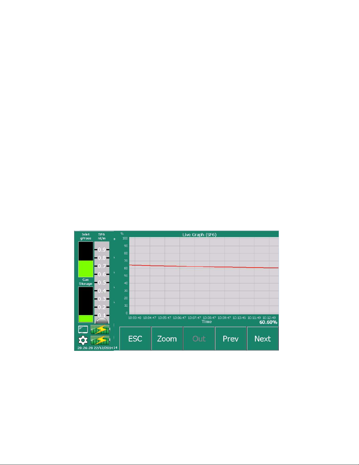
6.2 Live Graph Display
To view a live graph recording of the gas values or compartment pressure, press on the
appropriate label on the main display and the graph function will open. The main panel
shows a live display graph of the reading from the sensor. Use the “Esc” button to return to
the main display screen and the “Prev” & “Next” buttons to change the sensor you are
viewing. Each gas type is assigned a colour and this is shown in Figure 35 below.
Figure 11: Pressing on any gas name on the main screen will display a live graph of that measurement.
6.3 Line Purge Option
Pressing this button will activate the line purge feature. This uses a vacuum to remove all
the air from the special sample hose that is supplied with the analyser. It is recommended
to do a line purge of your hose at the start of a day’s testing to ensure no air gets mixed in
Page 19

with the SF6. If you are doing a series of tests it is not necessary to line purge every time as
the hose will be full of SF6 from the previous test.
The small volume of residual gas in the sample hose that is removed during the line purge
operation is vented to the “Bypass Port” (Figure 1-15). As there is a possibility that this
may contain SF6, the gas may be collected using an optional gas recovery bag. Connect the
recovery bag using a 4mm OD tube to the bypass port ( Figure1-15). There are screen
shots to remind you to do this should it be deemed necessary (see Figure 6).
Only use the sample hose that is supplied with this equipment to do your testing. This hose
has closed couplings that are gas and vacuum tight. The inside of the hose is lined with FEP
to make sure moisture and other gases don’t stick to the lining.
Connect the sample hose to the Gas Inlet socket (Figure 5) but DO NOT connect the other
end to the gas compartment. You will get a prompt and a diagram on screen to assist you
(Figure 6). Once you confirm that the hose is correctly in position the pump will run for
approximately 45 seconds to extract all the gas from the line. Afterwards you will receive a
prompt stating the line purge is complete. The sample line is now ready to be connected to
the gas compartment for testing.
Figure 12: Line Purge takes 45 seconds to complete and finishes with the above message
If you have the line attached to the gas compartment so there is pressurised gas present
then the pump will stop after a few seconds and question if the hose is still connected (see
Figure 2 - 4). This is a safety feature.
Note that occasionally the H2O sensor will display “U/Range” after a line purge because the
vacuum causes the moisture to drop below the minimum reading. This is not a problem
and the sensor will recover itself as soon as the analyser is pressurised with new SF6.
Page 20

6.4 Pump Back Option
If you have completed a test, or have gas in the storage bag, or have a bag that is full then
you can pump the gas back in to the gas compartment or gas recovery unit with this option.
You will receive a screen message and a diagram asking you to check and confirm the
sample hose is connected to the gas compartment (Figure 2 – 2). After confirmation, the
internal compressor will activate to pump all the SF6 back into the gas compartment.
Depending on how full the bag is and the pressure of the gas in the compartment this can
take up to five minutes to complete but is typically much faster than this. Once all the SF6
has been removed from the analyser the compressor will switch off and a message will
display confirming you can now remove the sample line again.
Page 21

6.5 Start Delay
In certain test environments, you are required to walk away from the equipment while the
test is being performed. The Rapidox allows the user to enter a start delay time in the
Sampling Menu. When enabled, the unit will count down the delay time before starting a
test. The feature works in both Timed and Continuous modes. To enable or edit this
function press “Menu” followed by “Sampling” to display the following screen. Press on the
button labelled “Start Delay” and enter a delay time in minutes. Set zero for no delay. The
minimum time delay is 0.1 mins (6 seconds) and the maximum time delay is 10 minutes.
Press “Set” to store the new value.
Figure 13: Use this feature to set a Start Delay time before a test begins
Figure 14: Enter a time up to ten minutes to use a delayed start
Page 22

Figure 15: The delayed start is shown on the screen before a sample commences
6.6 Working with Pre-Loaded Test Parameters
The Rapidox has several commonly used SF6 test parameters pre-loaded for quick and easy
selection. The list includes CIGRE and IEC international test standards as well as the option
to create and name your own custom test. Note that the dewpoint values used in these
standards are “Over Ice” i.e. frost point. To set up this function press “Menu” and then
“Sampling”. The pre-loaded tests are accessed by pressing the “Edit” button alongside the
label “Test Parameter”:
Figure 16: Pre-loaded test parameter screen. Press the “None” button to remove any tests that have been
selected.
Page 23

On this screen the user can remove any tests by pressing “None”. This will clear all
previous selections. To select the relevant test simply press on the labelled button of
choice and the pass/fail alarm settings will be loaded as displayed. Or if the user wants to
create a new bespoke test click on the button labelled “Custom” to access the editing
screen.
Figure 17: Custom test parameter edit screen
By clicking on the button below “Name” the user can re-name the test e.g. “Taiwan GIS
recycle”. Next the three gas parameters can be edited in turn. For each gas a pass/fail set
point can be entered as well as > and <. Or alternatively the test can be disabled for the gas
in question. Once the custom test parameters are set up press “Set” to store them. Pressing
“Back” returns you to the Sampling screen where you will see that the test name has
changed to your custom name. This new test can be selected and used in the same way as
the standard tests until it is edited and modified again.
With the test of choice selected the user can return to the main screen and begin sampling
gas. If the readings are outside the test parameter, the screen will display “FAIL” in red
alongside the gas symbol. Or if the sample is within the test parameter the word “PASS” in
green will be displayed. This information is logged and printed as a permanent record.
6.7 Working with SF6 and N2 mixtures
In certain countries SF6 is mixed with dry nitrogen in gas compartments. In this case it is
possible to reconfigure the analyser, so the balance gas analysis is displayed as the nitrogen
content. This option is not factory enabled and requires a re-boot to operate if selected.
To enable the N2 Balance option press ”Menu” and “Options” followed by “System Control”.
Enter the admin password (default it 8888) to continue.
Page 24

Figure 18: Use the System Control Menu to switch on / off the Balance Gas option
Select YES and press SET. The analyser will respond by asking to re-boot to enable this
function. Once restarted the main screen will now display N2 as the balance gas.
Figure 19: Main screen with N2 mode enabled.
6.8 Working with SF6 and Air mixtures
With the N2 balance mode enabled as described above in section 6.7, it is possible to change
the display to indicate “Air” instead of “N2”. This option is enabled in the “Set Units” menu
as described in section 7.7 below. In this case the Set Units menu is modified as shown in
Figure 20 below.
Page 25

Figure 20: With the balance gas option enabled it is possible to change the display units from “N2” to “Air” if
required.
Figure 21: With Air selected as the unit for the balance gas, the display now looks like this.
The balance mode can be enabled or disabled ay time by the use by accessing the System
Control Menu. A reboot is required to complete the task.
6.9 Working with SF6 and CF4 mixtures
*This feature is specified on ordering and may not be available on your instrument*
Page 26

In certain cold countries SF6 is blended with carbon tetrafluoromethane (CF4) normally in a
50:50 mix. This is used as an anti-freeze to prevent the SF6 from becoming liquid at
extreme cold temperatures.
This Rapidox will correctly measure the SF6 and CF4 content of your gas mixture in the
range specified using a combination of sensor readings and mathematics. To enable the
CF4 reading option press “Menu” followed by “Options” and “System Control”. Enter the
admin password to enter this menu (default is 8888) Here is an option “SF6 / CF4 mix in
use”. Please select Yes if you are using CF4 mixtures or No if you are using SF6 only. It is
important the CORRECT option is selected to ensure accurate readings are maintained!
Please see section 7.4 for full details. Note that the analyser must be re-booted if this
option is required.
Figure 22: To select CF4 mix operation use the menu option “Sampling” to select “YES”
Figure 23: When working with CF4/SF6 blended mixtures select this option and re-boot the analyser
Page 27

7 Rapidox Menu System
Pressing “Menu” enters the main Rapidox Menu system as seen below. Press “Back” to
return to the main analyser screen. If padlocks are displayed then these options are
password protected. See 7.9 for more information on passwords.
Figure 24: Rapidox Main Menu Screen. Note that on the pump back versions of this analyser the alarms are
disabled
7.1 Calibrate
Use this screen to calibrate the gas sensors should they require updating. Note that it is not
possible to field calibrate the H2O sensor because it has a special factory calibration over
many measurement points. Should the H2O sensor need re-calibrating please contact SMC
Sensotec for advice.
Page 28

to the Rapidox u
sing the sample hose
Rapidox using the sample hose
Rapidox to purge the cal gas from the system
Figure 25: Main calibration screen
During calibration, the cal gases are either diverted through the analyser and ejected via
the Bypass Port (Figure 1-15) so no gas enters the storage bag (set unit to CONTINUOUS
mode) or the cal gases enter the internal storage bag so no gas escapes intro the
atmosphere (set unit to TIMED mode). For the latter the calibration time is restricted to
around eight minutes until the storage bag is full. At this point the calibration will stop and
warn you to pump back. It is recommended that timed mode is selected when calibrating
with SF6 gases and continuous mode is selected when calibrating or zeroing with nitrogen
gases (eg toxic gases).
If calibrating with the bypass port, either connect a suitable gas recovery bag to this port or
ensure that a tube is connected to vent the gas to the outside air, subject to local laws and
regulations. After calibration the analyser sample hose must be line purged before further
sampling of SF6 is performed. This will ensure that no residual calibration gas gets mixed
with the sample gas and inadvertently pumped back into a gas compartment. Various
simple diagrams are displayed on-screen to make it easy to follow the correct sequence.
These are as follows:
1) Attach a pressurised nitrogen gas bottle
3) Attach a pressurised SF6 gas bottle to the
Figure 26: Various prompts are displayed on the screen to assist you in performing a calibration
2) Disconnect the nitrogen gas source
4) Attach a suitable gas recovery bag to the
Press on the option you have chosen to either zero or span calibrate the sensor of choice.
To zero the sensors first make sure that you have fresh air or nitrogen flowing through the
analyser. To calibrate the span of the sensor you will need a gas bottle of known
concentration gas (normally 100% SF6 and 100ppm SO2). The current calibration values
Page 29

are displayed on the calibrate screen as seen in Figure 25 above but these can be changed if
they do not match the value of your gas bottle.
You can load a previous calibration by pressing “Load” and you can save the calibration you
have just performed by pressing “Save”. All calibrations including the initial factory one are
stored on the hard drive of the analyser.
Figure 27: Historical calibrations can be re-loaded and new ones saved using the “Load” and “Save” buttons.
Figure 28: Use the “Zoom” button to magnify the graph when calibrating & “Out” to return to full
The current calibration gas concentration is shown in the top right hand corner of the main
screen. To change this value press “Conc” and enter a new value using the number pad.
This will be remembered for next time.
Page 30

Figure 29: The zero and span calibration gas concentrations can be modified by the user
Once you are happy that the reading is stable press “Cal” to save the new calibration. Use
the “Out” button to redraw the graph full scale. Use the “Back” button to return to the main
calibration screen. Repeat the process for any other sensors that you want to calibrate.
Note that if you calibrate with the wrong gas or try to calibrate ‘back to front’ the analyser
will give you a warning to check before proceeding.
Figure 30: To complete the calibration press “Cal”. Note that the analyser will warn you if the expected value
is out of range.
Page 31

7.2 Data-Logging
The test set data-logs all parameters and test results constantly whilst the machine is
operating. The data is stored indefinitely until the hard drive is full and then data will be
overwritten oldest first. There is sufficient space on the hard drive for a minimum of
twelve months of continuous data storage based on how the unit is used. You can use this
option to search, review and re-graph historical data.
Figure 31: Use this screen to select data-files stored in date blocks and view them in graph form.
Use the “Prev” and “Next” buttons to search though the history of data files. Press the “Esc”
to stop searching. Each session is recorded as a separate file on the hard drive. To return
to the current set press “Today”. To view the data as a graph press on the file icon of
interest and press “Go”.
A list of separate files representing sessions for the selected day are now displayed. Use
the “Up” and “Down” buttons to scroll the list and select the session of interest. Note that if
the test was timed then the end result can be displayed and reprinted, as well as graphed.
If the test was continuous then some viewing options will be disabled. If the test has a “*”
alongside it then this indicates the data are a complete test, as opposed to un-starred tests
which are either continuous measurements or a test where the user aborted before the
timer reached zero.
Page 32

Figure 32: The Data is loaded from the hard disc drive and displayed on the screen
To display the basic test result press “Show Results”. The result information will be
displayed as follows:
Figure 33: The Data is loaded from the hard disc drive and displayed on the screen. Here it can be printed
out.
To show a full graphical reporesentation of the sample test press “Graph Sample”. A full
colour graph of the test will be displayed as shown in Figure 34. Note that if the data is
from a large continuous test that it may take up to a minute to load and graph the results.
The graph Y axis is set to display the percent scale of the sensor so that all types of sensor
reading can be shown on a single graph. Press Next and Back to display individual gas
charts.
Page 33

Figure 34: Historical data-log graph with colour coded key
Figure 35: RGB Colours used for each gas type shown on a graph. Not all gas types are fitted to Rapidox
machines.
Pressing “Back” and “Next” will redraw the graph with a single gas or parameter to aid with
clarity. Using the “Options” button seen on Figure 32 the user can set a default choice for
what sensors are displayed on the historical graph:
Page 34

Figure 36: The user can customise the historical graphs using the “Options” button and selecting which
sensors to display and which to hide.
7.3 Auto Abort
The Auto Abort function allows users to set limits for toxic gases entering the analyser.
This helps to prevent damage to the equipment if excessive amounts of harmful gases such
as SO2, H2S, CO and HF enter the pipework. With the function set and enabled as soon as
any toxic gas level rises beyond the limit set, the test will abort, and the gas will be returned
to the compartment if auto-pumpback is enabled. To enter this function press “Menu”
followed by “Auto Abort” to see the following screen:
Figure 37: Auto Abort function. Depending on what toxic gas sensors are fitted a list of gases will be present
here.
Page 35

Note that you cannot set over-gas limits for SF6 CF4 and H2O. Only the toxic gas sensors
fitted to your machine will be listed here. Toggle the Enable/Disable button to switch on
the over-gas protection. Press on the gas value to edit the over-gas set point. Toggle the
pumpback switch to “Auto” or “Manual”. Once all the settings have been configured press
“Set” to store permanently.
If a gas reading exceeds an over-gas limit, then the analyser will report this as shown
below:
Figure 38: Message indicating that the SO2 over-gas limit has been exceeded. The test has been aborted and
the gas needs to be returned to the compartment.
7.4 Sampling Modes
You can choose the method of gas analysis as “Timed” or “Continuous” mode. For normal
testing Timed mode should be used in this mode the user selects a fixed time to sample gas
of eight minutes. The analyser then samples for this period and then displays the result on
the screen until the next sample is required. Multiple repeat tests are allowed, and the
testing can be aborted at any time. You can choose if the gas is automatically pumped back
after each test is completed and select if you would like an automatic print out of the
results at the end. During the test it is also possible to enter the live graph viewing mode.
In “Continuous” mode the analyser will sample gas permanently and pass the waste gas out
through the bypass port. A separate SF6 gas recovery system is required to prevent the gas
entering the atmosphere. This mode is used exclusively for calibration, validation and
service purposes.
Page 36

For both modes There is an option to identify the sample with a name (e.g. “GIS Station 3”)
that is displayed on the main screen. This name is also recorded on the data log file and on
the print out.
7.5 Timed Mode
Figure 39: Use this option to change the sampling method from “Timed” to “Continuous” and set the sampling
duration and other options.
The sample duration is fixed at eight minutes in this mode. For accurate dewpoint readings
the H2O sensor is cleaned every cycle which takes just under four minutes to complete, and
a further four minutes are required to get a stable reading.
If desired, a start delay can be incorporated to allow the user to walk away from the
equipment during testing. See 6.5 for a full description of this feature. It is recommended
that three repeat tests are performed to make sure that the sample line and equipment has
fully dried down and the dewpoint reading is accurate. If the dewpoint measurement is
still falling, then repeat the test again until a stable and consistent measurement is
obtained.
Note that the unit waits thirty seconds in between each test before starting the next one.
This allows all the sample gas to re-disperse inside the gas compartment prior to new
sampling.
Tap on the buttons labelled “Line Purge”, “Pump Back” and “Print Results” to toggle these
options on or off during a test. Setting “Line Purge” to “Auto” will cause the analyser to ask
you to do a vacuum purge of the sample line prior to each sample. This is important to do
on first use but may not be necessary each time so it is suggested this is left on “None” until
you are more familiar with your testing regime. Setting the “Pump Back” option to Auto
Page 37

will force the analyser to pump back the gas into the compartment after each set of tests is
completed. This is a normal procedure, so it is suggested to leave this set to “Auto”. Both
these options can also be manually commanded from the main display screen as well. Note
that if you choose multiple tests using the “Number of Tests” button then the “Auto” mode
will pump back after each to prevent the storage bag from over filling. Setting the printer
option to Auto will produce a print out of every test result if required. It is normal to have
this option set to “Auto”.
Figure 40: The Location name can be edited here using the alphabet keypad. Names are displayed on the
main screen and are printed and saved with the data.
Figure 41: During a “Timed” test the main screen displays a count down while the sample is being taken. The
results are displayed after the clock reaches zero. Press “Graph” to review the live data and “Abort” to abort
the sample mid-run.
Page 38

Figure 42: If during sampling the user wants to escape, pressing the “Abort” button will stop the sample and
the screen will show -.- to indicate that the sample was incomplete.
7.6 Continuous Mode
Figure 43: Continuous Mode set up page
This mode is used only when calibrating, validating or servicing the analyser. When this
mode is set, the test gas is diverted through the analyser and sent to the Bypass Port
(Figure 1-15). No gas enters the storage bag in this mode. Consequently, several of the
options are greyed out as they are not applicable in this mode.
The gas leaving the bypass port may be either collected for recycling using an optional gas
recovery bag or vented in accordance with local regulations, using a length of tube
Page 39

connected to the port. Note that each time the analyser is started, a reminder screen will
be displayed as shown in Figure 2 number 5).
In this mode the start delay option is still available. See 6.5 for a full description of this
feature. An additional option is available called “Free Flow”. This option is only used when
connecting external calibration equipment such as mass flow controllers dewpoint
generators. Selecting yes will disable all the flow control on the analyser which may
otherwise interfere with external flow control equipment. Leave this option set to “No”
unless you are working with such equipment.
Note that in continuous mode the dewpoint sensor will clean itself five minutes after
powering on and then every thirty minutes afterwards. During the two minute clean
period the display will indicate “Wait” while the sensor is off-line. Occasionally the
dewpoint sensor will perform a more advanced clean cycle which lasts slightly longer and
repeats itself up tot six times. If you observe this please leave the analyser running until
the cycle is complete and readings settle down again.
7.7 Set Units
Use this menu to change the units displayed by the analyser for the different measurement
parameters. The number of decimal places displayed can also be set here. Use the “Back”
button to return to the main menu. Note that you can also change the units directly from
the main display screen by tapping on them with your finger.
Figure 44: Setting the display units for the different sensors. T. Once selected the choice will be saved as the
default until changed again.
7.8 Date & Time
Page 40

There are various options for setting the analyser date and time and how it is displayed.
This information appears in the bottom left-hand corner of the display and is used for datalogging and record keeping.
Figure 45: Use this screen to set the date and time and how it should be displayed on the main screen.
7.9 Passwords
Default password USER = 2222
Default password ADMIN = 8888
Various levels of password protection can be set allowing access to selected menus and
options. This gives the user full flexibility to set the analyser up in a way that restricts
access only to sensitive screens and settings if desired. A four digit numerical
administrator password is required to enter the password screen. The default admin
password is 8888 but this can be changed later:
Page 41

Figure 46: To enter the password menu the user must enter the Admin password. The factory default is 8888.
Once you have entered the password menu as the Administrator then you can set the
restrictions and change the passwords as you so desire. There is an Admin password (used
to enter only the password screens) and a user password (used to access menus and
options on the analyser). The default factory user password is 2222. Once a menu is set to
“User” a padlock symbol will appear on the button and to continue the user password will
need to be entered to gain access.
Figure 47: The password administration screen allows sensitive menus to be locked with a user password.
Page 42

Figure 48: Once a password is enabled the user password will have to be entered to gain access to the menu
button that is locked.
Press “Set” to store the new settings. Please contact SMC for advice about how to recover a
lost Administrator password.
Page 43

8 Options Menu System
The Options Menu displays various settings that the user may use to set the analyser up
initially. Also included here are some diagnostics and other system tools. The “Data
Transfer” button remains grey until you insert a memory stick into the socket (8) as shown
in Figure 49. If padlocks are displayed then these options are password protected. See 7.9
for more information on passwords.
Figure 49: List of options Menu. The “Data Transfer” option remains grey until a suitable USB memory stick is
attached.
8.1 Data Transfer
Use this function to transfer results and sample data onto a memory stick and view with
Excel or similar programs. The memory stick should have sufficient space available to
transfer the files selected. A warning is given if there is insufficient space.
Select a start data and end date of interest and the size of the files to be transferred will
display. Press “Copy Results” to transfer just the basic results of each test (as printed) or
“Copy Data” to transfer the complete data log file.
Page 44

Figure 50: Use this screen to select the range of data to transfer onto your memory stick
Figure 51: Press “Copy” to begin the transfer. Do not remove the memory stick until told to do so.
Page 45

Figure 52: It is now safe to remove the USB memory stick.
The individual results file is in csv format that can be opened directly into Excel. Each test
is listed in order of date and time and each sensor result is placed on an individual row:
Page 46

Figure 53: Basic test results downloaded from the Rapidox are easily imported into an Excel spread sheet.
The complete data log files are also in csv format and can be opened directly into Excel.
This time the tests can be re-graphed as shown in Figure 54 using the functions available in
Excel.
Page 47

Figure 54: Data from the Rapidox is easily imported into an Excel spread sheet.
8.2 System Control
This options menu is used to set how the line purge and pump back operates and to
manually allow a purge of the complete system. As a complete system purge can involve
releasing small amounts of SF6 into the atmosphere if precautions have been ignored it is
generally a password controlled menu option.
Figure 55: For analysers with CF4 option enabled this is what is displayed
Page 48

Figure 56: For analysers NOT fitted with CF4 option this is what is displayed.
Pressing “System Purge Now” will perform a complete vacuum purge of the analyser
including all pipework, sample hose and gas storage bag. This is normally only required if
the analyser has just been calibrated and the user needs to purge the system of calibration
gas, or contaminated gas has been allowed to enter the machine. Once purged the analyser
is ready to take gas samples again.
Pressing “Pump back now” manually operates a pump back cycle. This option is also
available from the main display window. Once pressed the analyser will prompt you to
connect the sample line to the gas compartment and begin pumping back. Depending on
the pressure in the gas compartment and the volume of gas in the bag the pump back cycle
can take up to five minutes to complete.
“SF6 / CF4 mix in use” enables or disables the CF4 measurement mode. This function
requires a system reboot and is described in detail in section 6.9 above.
“Display Balance Gas” changes the main display so that the missing balance is shown as
either nitrogen or air. This function requires a system reboot and is described in detail in
sections 6.7 & 6.8 above.
The option to set a line purge before every test should be set to “no” unless instructed
otherwise by SMC.
8.3 Gas Cylinder Testing
The “Gas Cylinder Testing” option is used when you want to use the analyser with a gas
bottle of SF6 rather than a switch gear or circuit breaker. With this option set to “Yes” the
Page 49

analyser will accept gas directly from a gas bottle fitted with a regulator. A small gas
cylinder icon is displayed on the main screen to indicate this mode is in operation.
When sampling directly from gas bottles, it is normal for the regulator pressure to drop
momentarily when the test begins and in “normal” mode this can cause the Rapidox to stop
the test. In this cylinder mode, pressure drop monitoring is suspended making it easier to
sample directly from a bottle.
Note that in normal circumstances you cannot pump back directly into a gas cylinder
unless the internal cylinder pressure is below 10 bars. Auto pump back should normally be
disabled in this case.
8.4 Auto N2 System Clean
On occasions where the gas analyse has become contaminated with toxic gases such as SO2,
H2S, CO or HF, or the sample was excessively wet, this N2 System Clean mode allows the
entire analyser to be purged with bottled nitrogen to clean and dry it. Using this mode the
user is instructed to attach a cylinder of nitrogen and the unit will then run automatically
until all readings on the toxic gas sensors have reached zero once again. Nitrogen is fed into
the storage bag until it is full and then the gas is purged out of the instrument via the
bypass port using the pump. The auto clean mode will repeat itself up to a maximum of
XXX times if necessary.
8.5 Language
The default language is set to English but the user can change the screen language to
Spanish, French, German, Chinese (Simple or Traditional), Korean, Turkish or Portuguese.
Note that the analyser will request a system reboot if a different language is selected.
Page 50

Figure 57: Use this option to change the language setting of the analyser. Requires a system re-boot. Not all
options are shown on this screen
Figure 58: The analyser will ask you to confirm you really want to change the language before performing a
re-boot.
8.6 Screen Colour
There are several choices of screen colour and two choices of text colour (black or white).
Use the menu below to change the colours to your preference.
Figure 59: Use this option to change the colour scheme of the display
Page 51

8.7 Screen Brightness
The brightness of the screen can be increased or decreased using this menu option. The
screen brightness does have a significant impact on the battery life of the instrument.
There is also a screen saver option that can be enabled or disabled to help increase battery
life. The screen will darken when the saver is active. The user can select a delay time in
minutes before the screen saver switches on. The minimum time that can be set is one
minute.
Use this screen to change the brightness level. The value will be stored until changed again.
Figure 60: Use this option to adjust the screen brightness and screen saving feature.
8.8 Diagnostics
The diagnostics page provides information that is useful to SMC when diagnosing
problems with sensors or calibrations. The screen also displays readings from internal
pressure sensors and the battery. Please note that the screen is provided for information
purposes only.
Page 52

Figure 61: Diagnostics Page
8.9 Restore
This screen can be accessed and used to perform a factory restore of the analyser. In
normal circumstances this would only be required is the user is experiencing difficulties
with a calibration. Note that all data is lost during a factory restore and the sensors will
require a fresh calibration afterwards as only a basic calibration is loaded. The analyser
will ask you to confirm that you really do want to restore the machine and will reboot once
this has been completed.
Figure 62: Use this option to perform a system restore.
8.10 About
This screen is for information purposes only and shows the configuration of the analyser
including sensors and their ranges.
Page 53

Figure 63: This screen shows important system information about the analyser and sensors connected.
9 Troubleshooting
Q: When I switch on the unit the SF6 sensor display says “Wait”.
A: The infra-red SF6 sensor needs a bit of extra time to warm up before it can give
readings. The Rapidox waits for an internal signal coming from the sensor to say it
is ready before displaying readings. This should take around sixty seconds to
complete. If the “Wait” message does not clear please contact us for advice.
Q: When I start the machine I get a “Hardware Error Fault” message.
A: Very occasionally when the battery has been allowed to run very flat the start up
voltage isn’t quite enough to get the sensors re-started and this message can display.
To fix the problem try switching the unit off and removing the fuses for ten seconds
and refitting. Restart the analyser and in nearly all cases it will reboot correctly.
Q: One or more of the sensor readings is flashing.
A: The reading flashes if the value has gone above 101% of full scale and is to warn you
that the reading / calibration is just out of calibration spec. Please contact us for
advice
Q: I see other messages such as “O/Range” or “U/Range” instead of the gas reading.
A: This message displays if the reading goes above 102% or below 0%. This is usually
caused by a bad calibration Try recalibrating the sensor in question once more,
making sure that a sensible flow and pressure are being used. If all else fails try
restoring the analyser back to factory setting (see 8.9 for details). Contact SMC if the
message refuses to clear.
Page 54

Q: The H2O sensor reading shows “U/Range” right after I perform a line purge.
A: This is quite normal and caused by the fact the dewpoint sensor is sitting in a
vacuum. Because of the pressure compensation maths the reading can be pushed
below its minimum for a moment but this will fully recover once pressurised
compartment gas is applied.
Q: After a few minutes of testing the unit stops with question marks displayed.
A: Are you testing gas from a bottle? If you are, please check to see if you are using
“Gas Cylinder Mode”. The pressure in certain gas cylinders can drop a little during
testing and normal mode is very sensitive to this for safety reasons. Gas Cylinder
mode should be used in this case and the warnings should stop.
Q: One or both of the red charging lights is flashing on the top of the unit
A: If this happens then it means that the battery is too hot to charge. It is a safety
feature to make sure the lithium batteries don’t get damaged. If you are in a hot
location >30C then move the unit to somewhere cooler to charge – e.g. an air
conditioned office.
Q: One or more of the sensor readings says “Fault”
A: Please contact SMC for further advice.
Q: The Rapidox won't power up at all.
A: If the battery is flat then please connect the mains IEC cable and leave the unit to
charge for five to six hours. Note that you can use the analyser whilst it is charging.
The red LED should change to orange (almost fully charged) to green (fully
charged).
Q: The Rapidox still won't power up at all.
A: Please check that the two fuses located on the side are fitted and not blown. This
fuses are different and must not be installed the wrong way around. See Error!
Reference source not found. for correct fuse values.
Q: I get a “Sensor out of Range” warning when I try to calibrate
A: Check that the calibration gas value on the bottle matches the value you have
programmed into the Rapidox. If they are different then the Rapidox will get a
signal it is not expecting and try to warn you with this message. Check that you are
not trying to calibrate the sensor ‘backwards’ by applying span gas when you are
setting the zero point.
Q: I messed up the calibration procedure and the analyser is not working properly.
A: Return the box to the factory defaults using the instructions given in section 8.9 and
try again.
Q: I’m working in a location that has CF4 but can’t get the CF4 to display.
A: This option must be enabled by the user and the machine re-booted. Please make
sure that the gas does indeed have a blend of SF6 & CF4 before enabling. If you use
Page 55

this mode without CF4 present, then the results will be inaccurate.
Q: The SF6 reading seems very inaccurate
A: Please check the settings MENU – SAMPLING and check to see if the CF4 option is set
to yes or no. If it is set to yes and there is no CF4 in the gas then the SF6 reading will
be inaccurate. If everything seems normal, then please contact SMC for advice.
Q: The cooling fan seems to operate even though it is cold?
A: The cooling fan is set to operate each time a sample is taken to make sure no SF6 gas
leaks into the peli-case. Any build-up of SF6 inside the peli-case from external
sources can cause errors on the measurements. The fan also runs for five minutes
each time the unit is powered on.
Q: My storage bag says it is full before the 8 minutes are up!
A: The storage bag is five litres in capacity so at normal atmospheric temperature and
pressure there is at least ten minutes of storage space in the bag. So, in normal
circumstances you should never see a “Bag Full” message. However, since the flow
rate is based on gas density in exceptional circumstances it may be possible to fill
the bag too quickly: eg if the gas changes from SF6 to N2 very quickly during the
test. Also, in extreme weather conditions the volume of gas in the bag may be too
big even if the gas flow was correct. And the gas bag full may appear if calibration
takes longer than eight minutes. If the problem persists there may be an issue with
the calculated flow rate so please contact SMC for advice.
Q: Why does the sampling need to take eight minutes?
A: The Rapidox uses a special polymer dewpoint sensor to give high speed and reliable
dewpoint measurements. Normally these take hours to stabilise, but this sensor is
exceptionally fast. However, all dewpoint sensors are susceptible to drift so this
unit re-calibrates itself at the start of every test. This takes four to six minutes to
complete and we then need another two minutes to get a settle reading from it. So it
really has to be eight minutes to get a decent dewpoint measurement.
Q: Why do the dewpoint graph traces have such strange patterns?
A: The dewpoint sensor takes 4-6 minutes to clean and is off-line during this time. So
part of the trace of the H2O sensor is zero. After this both pressure correcting maths
and a regression algorithm kick in and these both take about thirty seconds of
readings before they become stable as they are both rolling averages. The result is
that only the last minute or so is a true reflection of the correct dewpoint.
Q: What is this 20°Cdp corrected function? Surely dewpoint is absolute?
A: Temperature corrected dewpoint seems to be a nonsense because it is an absolute
measurement unaffected by the temperature. However, most SF6 measurements of
dewpoint are performed using readings that are corrected somehow to 20°C. In
fact, what is happening is that the H2O is being measured in terms of relative
humidity (%RH), which is indeed temperature dependent. The Rapidox dewpoint
sensor measures humidity and temperature and then works out the equivalent
Page 56

dewpoint both at actual temperature (RT) and at the corrected point (@20°Cdp). In
hot countries this produces a drier reading and in colder countries this produces a
wetter reading. And of course if the ambient temperature is 20°C then the readings
are both identical.
Q: Why does it take several tests before the dewpoint falls to an acceptable level?
A: This question is the one we get asked about the most. Fundamentally water is a
very difficult gas to measure because it absorbs onto every surface and takes ages to
completely dry. And all the materials in contact with the gas including the bottle
regulators need to be high quality stainless steel or FEP. If you are in a hot and
humid country trying to run some tests then you have to accept that the hoses and
couplings will be covered in water and this will take a while to dry off completely. If
the first one or two tests are too wet but the readings are falling then please repeat
the testing a few times to observe a trend of dryness.
10 Warranty
The Rapidox analyser and the sensors have been carefully tested and inspected before
shipment and are guaranteed to be free from defective materials and workmanship for a
period of twelve months from date of purchase and delivery. However, if the analysis gas
contains corrosive gases or large quantities of particulates, sensor life may be shortened.
In the case of the latter, it is normally possible to insert a filter prior to the sensor head to
remove the particulate material. Damage caused to the sensors by contamination, chemical
attack or water ingress will not be covered by this warranty.
10.1 Conditions of Warranty:
1) This warranty is in addition to and does not affect any statutory rights of consumer
purchasers. This warranty is valid worldwide on a “back to base basis”.
2) This warranty covers breakdowns due to design or manufacturing faults; it does not
apply to damage, however caused, wear and tear, neglect, unauthorised adjustment or
repair, or any items of limited natural life.
3) In the event of failure, please take the following action:
a] Refer to the “Troubleshooting” section of your instruction manual to identify and
possibly correct the problem.
b] If the fault cannot be resolved, please contact the SMC service and repair centre at
the address given on the cover of the manual.
4) The warranty period applicable shall be 12 months from the date of delivery provided
that:
Page 57

a] Notice in writing of the defects complained of shall be given to SMC (The Seller)
upon their appearance, and
b] such defects shall be found to have arisen from the Seller's faulty design,
workmanship or materials, and
c] The defective goods shall be returned to the Seller's premises at the Purchaser's
expense if so requested by the Seller.
d] Any repaired or replaced goods shall be redelivered by the Seller free of charge to
the original point of delivery but otherwise in accordance with and subject to these
Conditions of Sale.
e] Alternatively the Seller shall be entitled at its absolute discretion to refund the price of
the defective goods in the event that such price shall already have been paid by the
Purchaser to the Seller, or, if such price has not been so paid, to relieve the Purchaser of all
obligation to pay the same by the issue of a credit note in favour of the Purchaser in the
amount of such price.
 Loading...