

SMC Networks PTE-50-CET Instruction Manual

INSTRUCTIONS MANUAL
PTE-50-CET
THREE PHASE RELAY TEST SET
REFERENCE: FAGVMV02
EDITION: 5/11/99
VERSION: 2

“The priority of EUROSMC, S.A. is to obtain the highest standards and quality in all
our products, serving to satisfy the expectations and necessities of our clients”.

PTE-50-CET
Sheet 2
INDEX
PTE-50-CET CONTENTS LIST ....................................................................................................................5
1. INTRODUCTION......................................................................................................................................6
1.1. MAIN FUNCTIONAL FEATURES ....................................................................................................6
1.2. APPLICATIONS................................................................................................................................7
2. OPERATIONAL PRINCIPLES.................................................................................................................9
2.1. GENERAL.........................................................................................................................................9
2.2. FRONT PANEL CONTROLS .........................................................................................................10
2.3. INTELLIGENT GENERATOR MODULE........................................................................................11
2.4. POWER SUPPLY...........................................................................................................................11
3. CONTROLS DESCRIPTION..................................................................................................................12
3.1. MAIN SUPPLY SECTION...............................................................................................................12
3.1.1. MAIN VOLTAGE SUPPLY...................................................................................................12
3.1.2. FIXED 110 V c.a. VOLTAGE SUPPLY ................................................................................13
3.2. TIMER SECTION: CHRONOMETER.............................................................................................13
3.2.1. CONTROL KEYS AND KNOBS: Selecting the function mode ............................................13
3.2.2. OPTIC INDICATORS AND DISPLAYS................................................................................14
3.2.2.1. Function mode indication.........................................................................................14
3.2.2.2. TIMER SIGNAL indicators.......................................................................................15
3.2.2.3. Timer reading...........................................................................................................15
3.2.3. CONNECTORS: Monitor Signal...........................................................................................15
3.3. POWER OUTPUTS........................................................................................................................16
3.3.1. LEVEL SECTION .................................................................................................................17
3.3.1.1. CONTROL KNOBS AND PRESS KEYS.................................................................17
3.3.1.2. OPTICAL INDICATORS AND DISPLAYS...............................................................19
3.3.1.3. TAPS: Output taps...................................................................................................20
3.3.2. PHASE SECTION ................................................................................................................21
3.3.2.1. CONTROL KNOBS AND PRESS KEYS.................................................................21
3.3.2.2. OPTICAL INDICATORS AND DISPLAYS...............................................................23
3.4. CHANNELS IN PARALLEL............................................................................................................24
3.4.1. USE......................................................................................................................................24
3.4.2. CONNECTION.....................................................................................................................24
3.4.3. EXAMPLE.............................................................................................................................26
3.5. GENERAL CONTROL SECTION...................................................................................................26

PTE-50-CET
Sheet 3
3.5.1. CONTROL KEYS .................................................................................................................27
3.5.1.1. Reset .......................................................................................................................27
3.5.1.2. Print.........................................................................................................................27
3.5.1.3. RS-232 serial port control........................................................................................27
3.5.1.4. SYNCHRONIZATION..............................................................................................27
3.5.1.5. HARMONICS selection ...........................................................................................28
3.5.1.6. Activating the BOOSTER ........................................................................................28
3.5.2. OPTIC INDICATORS...........................................................................................................28
3.5.2.1. RS-232 port indicator...............................................................................................28
3.5.2.2. SYNCHRONIZING REFERENCE indicators...........................................................29
3.5.2.3. Monitor state indicator .............................................................................................29
3.5.3. CONNECTORS AND FUSES..............................................................................................29
3.5.3.1. Voltage supply.........................................................................................................29
3.5.3.2. Monitor input taps....................................................................................................30
3.5.3.3. Auxiliary output to start an external timer................................................................31
3.5.3.4. RS-232 connector....................................................................................................31
4. FUNCTIONS: USE AND DESCRIPTIONS............................................................................................32
4.1. TIME MEASUREMENT..................................................................................................................32
4.1.1. SIGNAL MONITOR ..............................................................................................................32
4.1.2. TIMER MODE SELECTION.................................................................................................32
4.2. LEVEL SECTION: POWER OUTPUT............................................................................................33
4.2.1. INITIAL STATUS..................................................................................................................33
4.2.2. OUTPUT MODE SELECTION (I/V)......................................................................................33
4.2.3. OUTPUT RANGE SELECTION ...........................................................................................34
4.2.4. REFERENCE SOURCE SELECTION.................................................................................34
4.2.5. OUTPUT VALUES SELECTION..........................................................................................34
4.2.6. OUTPUT CONTROL: ON/OFF AND ALARMS....................................................................35
4.2.7. DYNAMIC TESTS: STEP TO 2
ND
VALUE ...........................................................................35
4.3. PHASE ANGLE SELECTION.........................................................................................................36
4.3.1. PHASE ANGLE SENSE.......................................................................................................36
4.3.2. DYNAMIC TESTS: STEP TO 2
ND
VALUE ...........................................................................37
4.3.3. USE OF EXTERNAL REFERENCE INPUT.........................................................................38
4.4. GENERAL CONTROL SECTION...................................................................................................38
4.4.1. SIGNAL MONITOR ..............................................................................................................38
4.5. COMMUNICATION IN BUS-PTE...................................................................................................39
4.5.1. EVENTS IN BUS-PTE..........................................................................................................39
4.5.2. EVENT TRANSMITTED BY A PTE-50-CET........................................................................39
4.6. SPECIAL FUNCTIONS...................................................................................................................40
4.6.1. AUTO OFF ...........................................................................................................................40
4.6.2. FAILURES DETECTION......................................................................................................40

PTE-50-CET
Sheet 4
5. SPECIFICATIONS .................................................................................................................................42
5.1. POWER GENERATORS................................................................................................................42
5.2. INTERNAL TIMER..........................................................................................................................43
5.3. HARMONICS GENERATOR..........................................................................................................43
5.4. EXTERNAL REFERENCE INPUT..................................................................................................44
5.5. SIGNAL MONITORS......................................................................................................................44
5.6. AVAILABLE REFERENCES...........................................................................................................44
5.7. CONTAINER...................................................................................................................................44
6. TECHNICAL ASSISTANCE, AFTER SALES SERVICE AND WARRANTY.........................................45
6.1. WARRANTY...................................................................................................................................45
6.2. AFTER SALES SUPPORT.............................................................................................................45
6.3. OTHER EUROSMC PRODUCTS ..................................................................................................45
FIGURES INDEX
Figure 1: PTE-50-CET Front Panel...............................................................................................................9
Figure 2: Functional Modules........................................................................................................................9
Figure 3: Front Module................................................................................................................................10
Figure 4: Intelligent Generator Module........................................................................................................11
Figure 5: Main Supply..................................................................................................................................12
Figure 6: Timer Section...............................................................................................................................13
Figure 7: Power Output ...............................................................................................................................16
Figure 8: Level Output Selection.................................................................................................................17
Figure 9: Phase Angle Selection.................................................................................................................21
Figure 10: Channels Parallel Connection....................................................................................................25
Figure 11: General Control Sections...........................................................................................................27
Figure 12: Fuses Box ..................................................................................................................................30
Figure 13: Signal Monitor ............................................................................................................................31
Figure 14: Phase Angle Selection (European)............................................................................................36
Figure 15: Phase Angle Selection (American)............................................................................................37

PTE-50-CET
Sheet 5
PTE-50-CET CONTENTS LIST
• 1 Unit PTE-50-CET.
• 1 Nylon cover.
• 1 Voltage supply cable type Schuko.
• 12 Interconnection cables 2.5 mm
2
section (6 reds and 6 blacks).
• 1 Interconnection cable between PC and PTE-50-CET unit, by RS-232.
• 1 PTE BUS interconnection cable for two units.
• 1 Interconnection cable for external timer output PTE-50-CET type BNC.
• 4 Clips up to 50 A (2 reds and 2 blacks).
• 4 Clips up to 10 A (2 reds and 2 blacks).
• Replacement fuses:
− 4 Fuses 5x20 100 mA, fast.
− 4 Fuses 5x20 400 mA.
− 2 Fuses 5x20 500 mA.
− 4 Fuses 5x20 630 mA, fast.
− 2 Fuses 5x20 2 A.
− 4 Fuses 5x20 12 A, fast.
− 4 Fuses 5x20 6.3 A, fast.
• 1 Case key.
• 1 Warranty.
• 1 Measurement Certificate.
• 1 Instructions Manual.
• Equipment with 220 V ac volt age supp ly:
− 2 Fuses 5x20 6.3 A, included in the assembly switch ON/OFF.
• Equipment with 125 V ac volt age supp ly:
− 2 Fuses 5x20 12 A, included in the assembly switch ON/OFF.

PTE-50-CET
Sheet 6
1. INTRODUCTION
The PTE-50-CET is designed as a Portable Three Phase Unit that allows the user to test, as stand
alone unit or in combination with others, all type of protective relays.
Extremely compact and rugged, this unit incorporates the latest in the modern microprocessor technology
to achieve unbeatable output characteristics in terms of power, accuracy, low distortion, and dynamic
capability. This technology allows the unit to perform, without any external accessories, various specific
functions very often used in the relay testing.
All the output signals are digitally generated, amplified and controlled by the internal IGMs (Intelligent
Generation Modules) in terms of amplitude, phase and frequency. A high accuracy and stability are
obtained in the output waveforms, which are absolutely independent of the main supply.
Contained in an aluminum IP-65 case, with a membrane keyboard that allows full manual control, and a
RS-232 com port for computer control, the PTE-50-CET offers the best features actually available for on
site manual or automatic relay testing.
1.1. MAIN FUNCTIONAL FEATURES
The following are the more outstanding functions/features that the PTE-50-CET has:
a) TIMER MEASUREMENT
Used when measuring the timing response of relays during test. The digital timer which is
incorporated in the PTE-50-CET has a resolution of 1 ms and contains all the necessary controls
to select the starting and stopping of the timer whether it is external or internal, or when using the
monitor signal or via PTE-BUS.
b) AVAILABLE REFERENCES
The power output has three different references available:
• The main supply phase (Line).
• The PTE BUS (BUS).
• The External Phase Reference (current or voltage).
c) POWER OUTPUTS
The current or voltage outputs are available, up to 50 A in four ranges and up to 150 V in two
ranges respectively.
Any power outputs combination is possible: two channels can work in voltage mode and the
other one in current mode, or even all of them can work in voltage mode. In current mode, the unit
allows channels parallel connection so it can supply up to 3 x 50 A = 150 A.
All the outputs have a dynamic capability. The output regulation can work independently or
linked in a three phase system, when PTE units are working together interconnected through
the PTE BUS, any combination of dynamic steps to 2
nd
values, can be selected in amplitudes and
phase angles for any type of fault simulation.

PTE-50-CET
Sheet 7
d) EXTERNAL REFERENCES INPUT
Can be synchronized, in terms of frequency and phase with any external signal, from 0.1 to 25 A
in current, and from 5 to 300 V in voltage.
e) SIGNAL MONITOR
The unit has a Signal Monitor input that can work with dry contacts or with voltage signals from 5
to 250 V ac or dc.
f) RS-232 COM PORT
Used to control the equipment from an external computer, can be used to perform the following:
• Software calibration.
• Automatic testing.
• Direct printing of the test results in a RS-232 input printer.
g) PTE BUS
Allows the interconnection with any other unit of the PTE RANGE.
h) EXTERNAL TIMER CONTROL OUTPUT
Delivers a pulse signal, dry contact type, of 20 ms duration. This can be used to start an external
timer, for timing measurements. This signal is produced every time one of the power outputs
changes its status, or the Step key is activated in amplitude or in phase.
i) OUTPUT PROTECTION
The outputs and, in general, the unit, are electronically protected against overload, short-circuit
and over temperature. These alarms are indicated on the Front Panel.
Standard 5 x 20 mm fuses protect the rest of inputs and general devices included in the unit.
1.2. APPLICATIONS
a) AS STAND ALONE TESTING UNIT
• Synchronizing relays.
• Multifunction generator protection Relays.
• Harmonics relays.
• Overcurrent relays (up to 150 A).
• Inverse time overcurrent relays.
• Definite time overcurrent relays.
• Earth and neutral (including harmonics filtering).
• Voltage controlled relays.
• Directional relays.
• Differential relays.

PTE-50-CET
Sheet 8
• Single phase distance relays.
• Directional power relays (single and three phase).
• Maximum and minimum voltage relays.
• Dynamic test. Fault simulation.
b) COMBINED WITH A SINGLE PHASE CURRENT INJECTOR
• Three phase distance relays.
• Full three-phase network fault simulation.
• In general all types of relays which require 3 voltages and 3 currents to function correctly.
c) MISCELLANEOUS
Due to its good characteristics of accuracy and stability, the PTE-50-CET can test transducers,
energy meters and measuring instruments can be tested as well, in the following range:
• Three phase current up to 50 A (or 150 A single phase).
• Voltage in three-phase or single phase (up to 150 V).
• Harmonic selection, independent en each channel, up to the 5
th
harmonic.
• Three-phase angle from 0º to 359.9º.
PTE-50-CET
Sheet 9
Figure 1: PTE-50-CET Front Panel
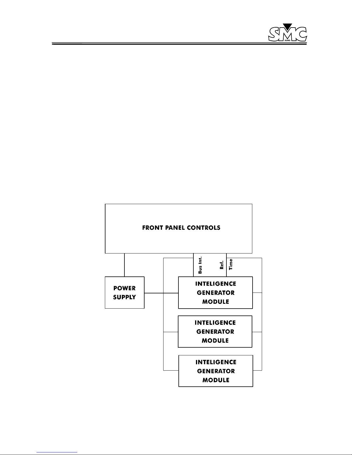
2. OPERATIONAL PRINCIPLES
2.1. GENERAL
In this section a general overview of the operational basic principles on which the PTE-50-CET is
based, are given in this section. An understanding of these principles should help in order to find new
applications, maintenance, etc.
Briefly, the unit has a user interface (Front Panel), that is communicated with the Power Amplifier
through the microprocessors incorporated. Of course, a power supply, security devices, transformers,
etc. need to be used as well. According with these, the unit can be divided in the following modules:
1. Front Panel Controls.
2. Intelligent Generator Modules (IGM).
3. Power Supply.
PTE-50-CET
Figure 2: Functional Modules
PTE-50-CET
Sheet 10
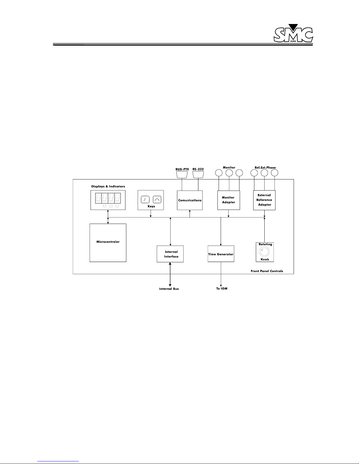
2.2. FRONT PANEL CONTROLS
Allows the user to communicate with the power output section of the unit in a manual way, or using a
software program. To achieve this, it has the following sections:
1. Displays and LED indicators: indicate the various selections made by the operator and the
status of the unit.
2. Press ke y controls: this is a membrane keyboard with acoustic feedback, in which the various
different functions available in the unit are selected.
3. Multi-turn co ntrol knobs: these are rotative pulse gen erators that are used to make the differe nt
selections desired on the displays indicators, in an easy and fast manner.
4. Monitor taps: contain the circuits to detect the status of the signals applied in these taps.
Figure 3: Front Module
5. External Reference Taps: contain the circuits to synchronize the power outputs to the phase
and frequency signals connected to these taps.
6. Communications: the PTE units have the capability to communicate with some external control
devices by RS-232 (allowing the user for printing results and calibration from the PC) and by
BUS-PTE, for interconnection with PTE RANGE units and control of these by a PC.
7. Internal Bus Interface: establishes the communication between the Front Panel and the
Intelligent Generator Module, via the microprocessors included in both.
8. Time Generator: it generates the high accuracy time reference necessary to generate the
internal phase and frequency.
9. Output taps: these are the taps of the auxiliary voltage supply of 110 V ac, the power output
taps, and the tap to start an external timer.
PTE-50-CET
Sheet 11
10. Microcontroller: it is one of the most important parts of the unit, which as its name indicates,
controls or establishes the flow of information between all the functional blocks previously
mentioned.
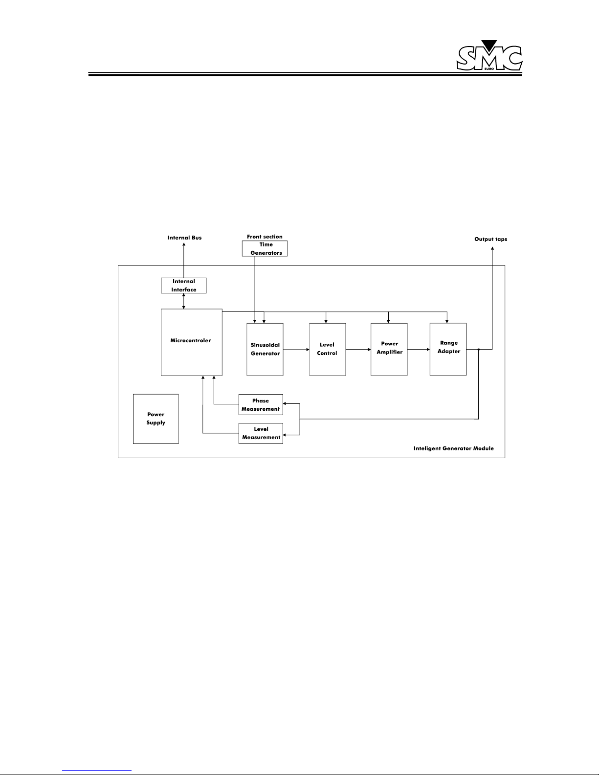
2.3. INTELLIGENT GENERATOR MODULE
Essentially, the IGM is a linear power amplifier, controlled by its internal microprocessor. It produces
the sinusoidal signal in the frequency and the phase selected. This is amplified and adapted by a
transformer in the selected output range. This generator also feedbacks the output level in voltage,
current, and phase, to the generation stage, thus achieving a high accuracy output.
Figure 4: Intelligent Generator Module
As shown in the block drawing and in the front panel control functions, a microprocessor is in charge
of supervising all the functions of the generator modules. These receive the output measurements and
make the corrections necessary in amplitude and phase to obtain the desired accuracy. Also they
store the calibration parameters, and use them to correct the selections made from the Front Panel.
2.4. POWER SUPPLY
As in all off the systems that produce an output which is absolutely independent of the main supply,
the PTE-50-CET needs to have a D.C. power supply, that converts the AC input of the main supply, to
a DC that supplies the power amplifiers. This is achieved by using a combination of switching and
linear DC power supplies.
PTE-50-CET
Sheet 12
3. CONTROLS DESCRIPTION
This section describes one by one and in detail all of the controls, indicators, displays, and connection
taps on the front panel of the PTE-50-CET. As well as the functions, marked indications and where they
are located will be shown in the figures.
To understand this clearly, sections will describe the controls, by their functions, and by their physical
position on the front panel. The different types of controls that you can find are classified as follows:
• KEY CONTROLS: this refers to the press key and rotating knobs.
• DISPLAY AND OPTIC INDICATORS: this refers to the LED indicators and the selection displays.
• CONNECTORS (TAPS): this refers to all taps (input and output), connectors, etc., which are
contained in the PTE-50-CET. This section describes all the connectors that are incorporated in the
unit. All of them meet international safety standards and are easily identified with their
corresponding identification marks on the front panel.
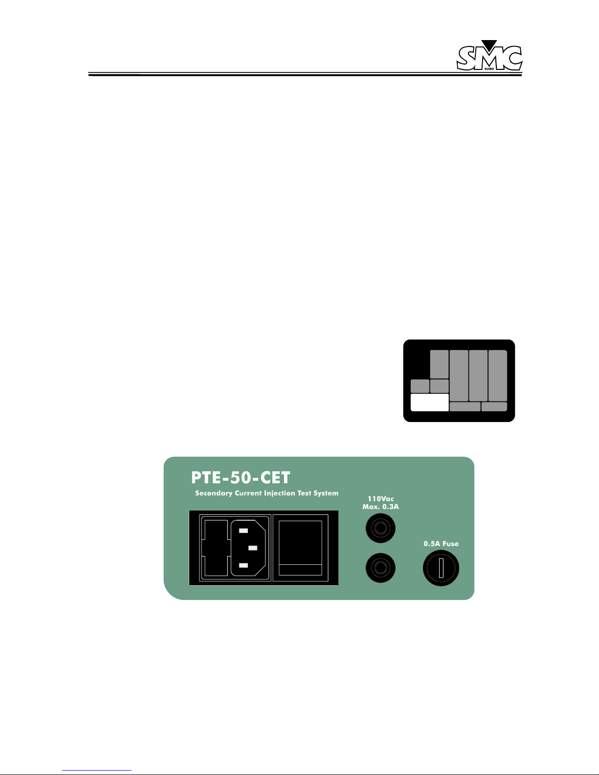
3.1. MAIN SUPPLY SECTION
3.1.1. MAIN VOLTAGE SUPPLY
The unit is supplied with SCHUKO type plug 2 poles with earth. Also
incorporated in the connector is a filter to avoid perturbations from the
main supply.
Figure 5: Main Supply
This is situated on the bottom left hand side of the unit and includes the following:
• Power supply with 2 poles and earth.
PTE-50-CET
Sheet 13
• Power supply fuse holder: to reach these fuses, the cover must be lifted as indicated in the
drawing. There are two fuses: the lower one is the active fuse and
the one located above is the spare fuse. The fuses are standard
type, 5 x 20 mm, 6.3 A..
• Power supply switch: it has 2 positions, ON/OFF. The unit is
disconnected when the red mark of the switch is visible.
3.1.2. FIXED 110 V c.a. VOLTAGE SUPPLY
This output is located in the lower central section to the right of the power supply switch. It consists of
2 black taps.
This output is always active when the unit is switched on. The taps have a distance of 19 mm which
is the standard two-pole plug size.
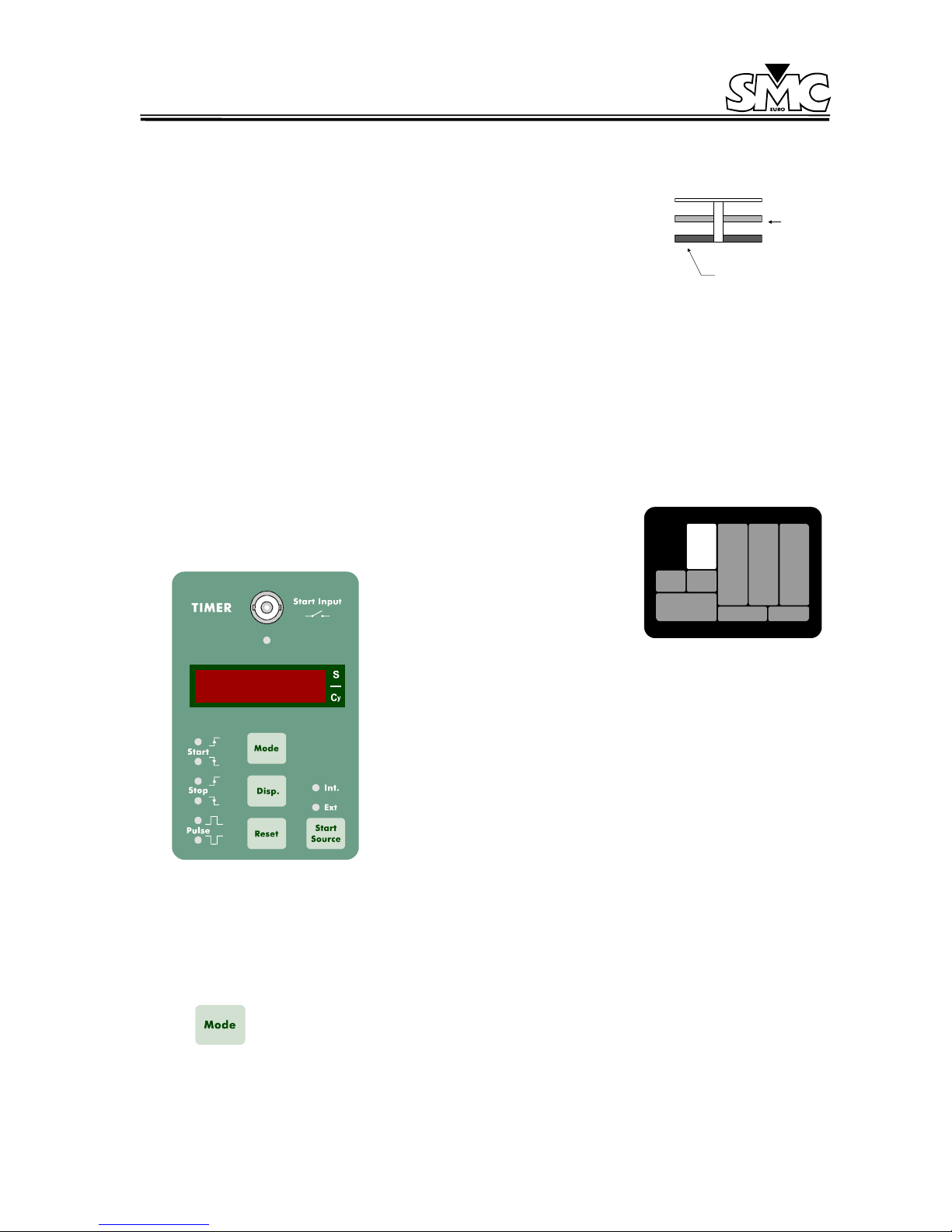
3.2. TIMER SECTION: CHRONOMETER
The Timer is located on the left-hand side of the unit and clearly
marked from the rest of the unit. It contains all the necessary controls
for various timing functions, which are explained below.
Figure 6: Timer Section
3.2.1. CONTROL KEYS AND KNOBS: Selecting the function mode
This section describes how to select the timer mode for the starting/stopping of the timer, the timer
reading, and how to reset it. The keyboard for the timer is as follows:
This key works in a sequential way, that is to say by pressing this key; the LEDs
will indicate the different selection combinations. There are different possibilities to
choose from, see 3.2.2.1.
ACTIVE
FUSE
 Loading...