

SMC Networks PTE-100-C User Manual
Current and voltage relay testing unit to 250 A
USER’S MANUAL
PTE-100-C
REFERENCE: FAAVMV02
EDITION: May 17 th, 2013
VERSION: 10
Quality is the core reference for EuroSMC’s activities, aimed to fully satisfy our
customers’ needs and expectations.
DISCLAIMER
The information, product specificatio ns, and technical data contained in this
document imply no contractual binding to EuroSMC’s responsibility. The user is
the sole responsible for the application of the products mentioned in this
document. EuroSMC explicitly exonerates itself from liability to accidents or
unwanted results, directly or indirectly derived from mistakes made in the
writing of this document. Copying or reproducing all or part of this document is
not allowed without the explicit written permission from EuroSMC. Due to
continuing development and quality improvements, EuroSMC reserves the right
to make changes in their products without notice.

INDEX
PTE-100-C PACKING LIST .......................................... 5
INTRODUCTION ......................................................... 6
GENERAL OVERVIEW ................................................. 7
Technology ................................................................................. 7
Power Section Design .................................................................. 7
Auxiliary Voltage Supply ............................................................... 8
Measurement and Control ........................................................... 8
DESCRIPTION ........................................................... 10
MAIN AC SUPPLY ............................................................... 10
Main Protection Fuses ................................................................ 10
POWER OUTPUT SECTION ................................................. 11
Output ON/OFF buttons ........................................................... 11
Regulation Variac ...................................................................... 11
Current Output taps .................................................................. 12
0-250 VAC voltage tap (OUT 1) ................................................ 12
0-350 VDC voltage tap (OUT 2) ................................................ 12
Display #2 ................................................................................ 13
Displayed Output selector .......................................................... 13
Current tap selection.................................................................. 14
Power Section Alarms ................................................................ 14
AUXILIARY VOLTAGE ......................................................... 15
Out 3: 0-250 Vdc Auxiliary Output ............................................ 15
Out 3 Overload Alarm .............................................................. 15
Out 4: 110 Vac Auxiliary Output ............................................... 15
TIMER SECTION .................................................................. 16
Monitor Input ............................................................................ 16
Time Display ............................................................................. 16
Timer control ............................................................................. 17
Timer start/stop modes .............................................................. 17
SPECIAL FUNCTIONS .......................................................... 18
MEASUREMENT FUNCTIONS ................................................... 19
CONTROL FUNCTIONS ........................................................... 20
COMMUNICATIONS ........................................................... 21
Serial RS-232 port ..................................................................... 21
PTE-BUS ................................................................................... 21
OPERATION ............................................................. 22
CURRENT AND VOLTAGE INJECTION ............................... 22
AC Current Injection .................................................................. 22
Overload protection .................................................................. 24
Voltage Injection ........................................................................ 24
AUXILIARY POWER ............................................................ 25
Out 3 variable DC auxiliary supply ............................................. 25
Out 4 fixed AC auxiliary supply .................................................. 26
TIME MEASUREMENT ......................................................... 26
The Monitor .............................................................................. 28
Timer start/stop modes .............................................................. 28
SPECIAL MEASUREMENT AND CONTROL FUNCTIONS .... 29
Voltimeter and Frequency Meter ................................................. 30
Output Current-related measurements………………………….30
Protecting your relay against test-related accidents ...................... 32
Testing instantneous over current……………………………….32
Pre-setting a current value .......................................................... 34
CALIBRATING THE PTE-100-C ........................................... 35
Required equipment .................................................................. 35
General Calibration Procedure .................................................. 35
SPECIFICATIONS ...................................................... 37
Output Characteristics…………………………………………..37
Special Functions…………………………………………………37
Measurement functions…………………………………………38
Voltage Supply .......................................................................... 38
Physical Dimensions ................................................................... 38
AFTER SALES SUPPORT ............................................ 39
WARRANTY ........................................................................ 39
CUSTOMER SUPPORT ........................................................ 39
OTHER EUROSMC PRODUCTS ........................................... 39
GENERAL DIAGRAM ................................................ 40
FRONT PANEL .......................................................... 41

PTE-100-C
5
PTE-100-C PACKING LIST
1 PTE-100-C unit
1 Nylon bag
1 AC supply cord
6 2-meter, 2.5 mm2 section test leads (3 black, 3 red)
2 2-meter, 10 mm2 section test leads (1 black, 1 blue)
1 2-meter RS-232 communications cable to PC
2 6-mm to 4-mm plug adapters
4 Clips up to 50A (2 black, 2 red)
4 Clips up to 10A (2 black, 2 red)
2 5 x 20 mm, 100 mA, FAST fuses
2 5 x 20 mm, 0.5 A, Standard fuses
1 Calibration Software CD-ROM
2 Case Key
1 Warranty Registration Form
1 Measurements Certificate
1 This user’s manual
USER’S MANUAL
6
INTRODUCTION
The PTE-100-C Relay Test Set is designed to test protective relays based on
single-phase current and /or voltage measurement.
Its small size, excellent output power and accuracy, quality features, and
ease of use, make this product one of the best choices available in its kind.
To achieve this goal, EUROSMC collected the opinion and suggestions of
various professionals and companies of recognized prestige and experience
in protective relay maintenance and commissioning. As a result, the PTE100-C features the following unique characteristics:
Robust mechanical and electrical construction.
Great portability.
Built-in measurement features to avoid carrying a large number of
instruments.
Results printout capability, when taking notes is usually difficult.
Software-assisted closed-case calibration with a Windows PC.
Functions to protect the relay being tested.
Easy, intuitive operation.
The PTE-100-C includes all the accessories needed for testing, such as cables, clips, nylon bag for transport, spare fuses etc. as standard equipment.
We appreciate your suggestions about the PTE-100-C and this manual, in
our commitment to improve our quality. Our technical staff will be pleased
to help you on any difficulties or questions that you may have.
Thank you for choosing EuroSMC products.
EUROSMC, S.A.
Pol. Ind. P-29 Calle Buril 69
28400 Collado Villalba. MADRID (SPAIN)
TEL: 34-91-91 849 89 80. FAX: 34-91-851 25 53
www.eurosmc.com
PTE-100-C
7
GENERAL OVERVIEW
Technology
The PTE-100-C combines state-of-the-art digital technology with the traditional regulation method based on a variable autotransformer and transformer.
Analogue and digital electronics convert signals in- and out from the unit in
order to be processed and displayed by an 8-bit microprocessor.
The power section is based mainly on electromechanical components.
The unit’s layout is arranged in modules and the number of moving parts is
kept to a minimum for easy and safe operation.
Power Section Design
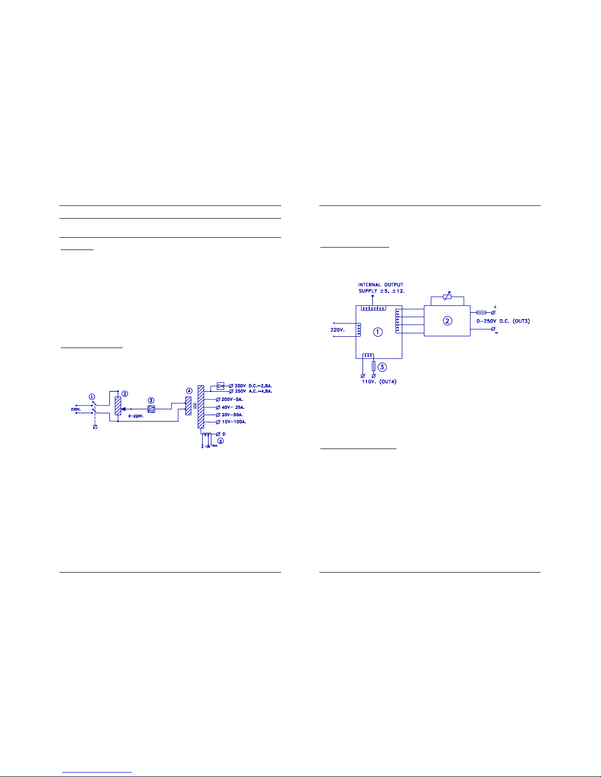
Classical, direct regulation and transformers are used to generate and control the high 1,000-VA power output, as shown in the following diagram:
1. An internal relay connects the main power supply to the variac under no-load conditions.
2. The single-phase variable autotransformer (Variac) regulates the
voltage at the primary winding of the output power transformer.
3. A static switch (Triac) guarantees a clean connection and disconnection of the Variac from the power transformer’s input.
4. A toroidal transformer guarantees the insulation of the output from
the main power supply.
5. A current measurement transformer, with one primary winding and
two secondaries with 250:1 and 50:1 respective ratios, is connect-
USER’S MANUAL
8
ed to the ‘zero’ output tap of the power transformer. Measurement
range switching is automatic.
Auxiliary Voltage Supply
By means of a transformer with multiple secondary windings, the PTE-100-C
features two independent auxiliary voltage outputs:
Out 3 is a variable 0-250 VDC stabilized, electronically protected
supply with a dedicated ON/OFF switch, and
Out 4 is a fixed 110 VAC. This fuse-protected output is permanent-
ly active whenever the equipment is switched on.
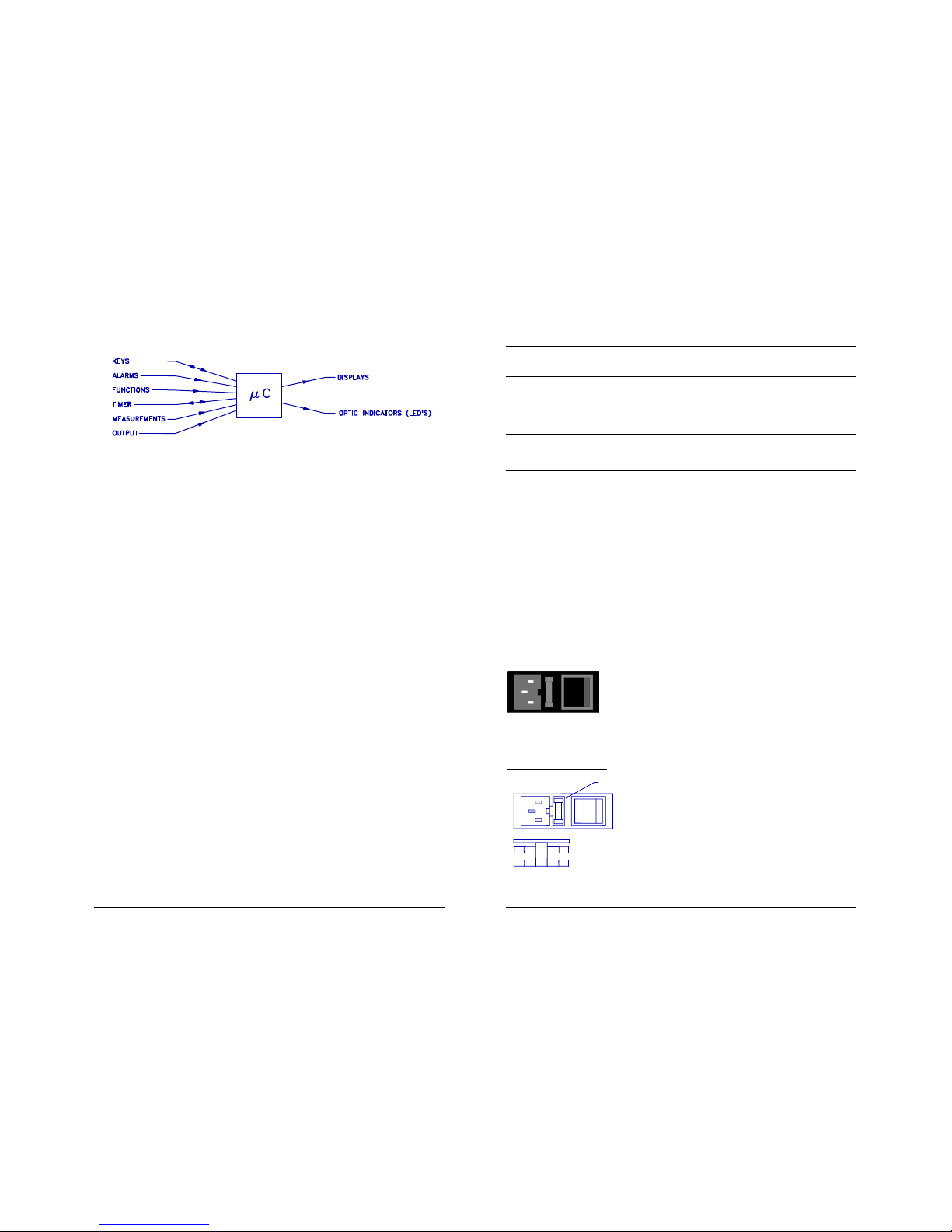
Measurement and Control
Analogue input is converted to digital values before it is processed and displayed. The following external or internal analogue magnitudes are measured:
Voltage.
Current.
Phase angle.
Temperature.
Displayed and/or used values like Impedance or Power are automatically
calculated from these magnitudes by the microcontroller.
PTE-100-C
9
The same micro-controller processes all the user’s control actions like output
on/off, the timer activation, the selection and display of function values, and
the protective alarms.
USER’S MANUAL
10
DESCRIPTION
All the elements in the front panel of the PTE-100-C are thoroughly described here. In-depth explanation of their use is given in the Operation
section.
Many buttons, namely those that perform a different function when held down,
effectively actuate when released, rather than when pressed. These buttons will
produce a “secondary function” when pressed until an audible beep is heard.
We will now describe the PTE-100-C along the following sections:
MAIN AC SUPPLY
POWER OUTPUT SECTION
AUXILIARY VOLTAGE
TIMER SECTION
SPECIAL FUNCTIONS
COMMUNICATIONS
MAIN AC SUPPLY
An AC supply block at the lower left-hand corner of
the front panel groups the power cord plug, a fuse
holder and the main on/off switch. Internal filters
prevent most AC perturbations from leaking into the
unit. The OFF position is indicated by a tiny circle in one of the faces of the
main switch.
Main Protection Fuses
The active (12A, Fast) fuse and a spare fuse
are included in the fuse holder. All the fuses
accessible from the front panel are standard,
5x20 mm cylindrical, and their current rating
and type are clearly printed.
SPARE FUSE
ACTIVE FUSE
FUSE
PTE-100-C
11
REPLACE BLOWN FUSES WITH IDENTICAL ONES ONLY. DAMAGE
RESULTING FROM INCORRECT FUSE REPLACEMENT IS NOT COVERED
BY THE WARRANTY.
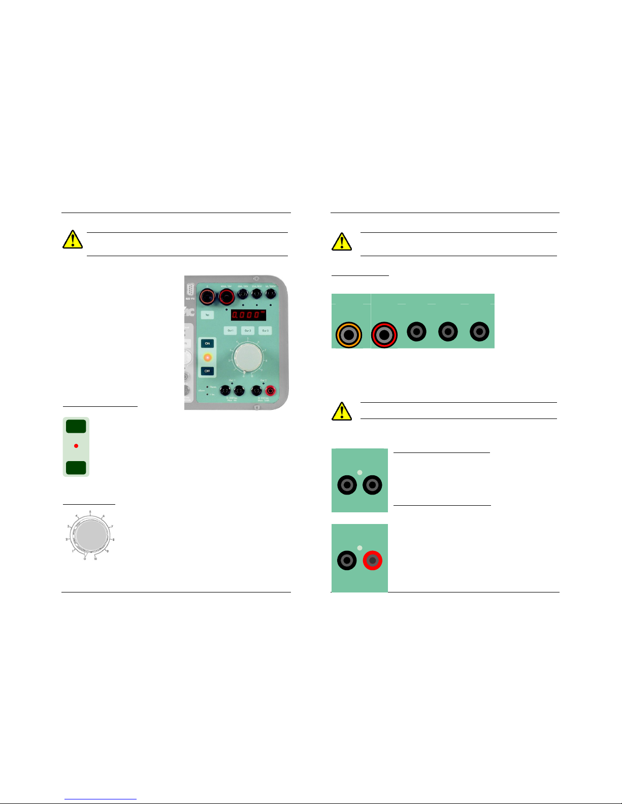
POWER OUTPUT SECTION
This is the right-hand section of the
front panel. It contains the main output control buttons, the regulation
variac, the Display #2, the current
and voltage output taps, the tap selector, the displayed output selector and
a few associated and alarm LEDs:
Output ON/OFF buttons
These buttons connect and disconnect the main power ouput,
i.e. the current output taps and the Out 1 and Out 2 voltage
taps. A red LED indicates the following output states:
OFF: The output has been intentionally switched off
ON: The output has been intentionally switched on
BLINK: The output has been switched off by the unit. This will
be further explained under the OPERATION section.
Regulation Variac
This knob controls the output level of the current and
voltage power taps. The numerical 0-10 round scale is
provided as a positional reference only. The actual
output level is shown in Display #2 and, at any given
regulator position, its value always depends on the
connected impedance. Regardless of the regulator’s
position, no power will be output when the output control switch is OFF.
Always handle this regulator with care.
ON
OFF
USER’S MANUAL
12
A harmful amount of current could be injected into the connected
load if you accidentally switch the output ON with the variac in a
position other than zero.
Current output taps
At the top of the power output section, four current injection taps are provid-
ed to adapt the
current output
characteristics to
the connected
load, as well as to
facilitate the output
level regulation.
Tap zero is the common reference. If you are testing with currents ranging
from 0 to 50 A AC, for example, connect the load between the common
tap and the tap labeled “50 A / 20 V”. If you are using 4 mm bananas, you
will need the supplied 6-mm to 4-mm plug adapters for the common tap
and the 100 A tap.
Press these adapters all the way down before pulling them up for
removal.
0-250 VAC voltage tap (OUT 1)
Out 1 is located on the left immediately underneath the
variac knob. Output from this tap is measured and
regulated in AC volts. Maximum throughput current is
4A in non-continuous service.
0-350 VDC voltage tap (OUT 2)
Out 2 is located on the right of Out 1. Its output is
measured and regulated in DC volts. Polarity is indicated by the black (negative) and red (positive) plug colors.
A standard 19 mm plug can be used with this pair of
connectors. All these taps and connectors comply to
the latest international standards and electrical safety
regulations.
0 100A/10V 50A/20V 25A/40V 5A/200V
Out 1
0-250 Vac
Max. 4A
Out 2
0-350 Vdc
Max. 2.8A
PTE-100-C
13
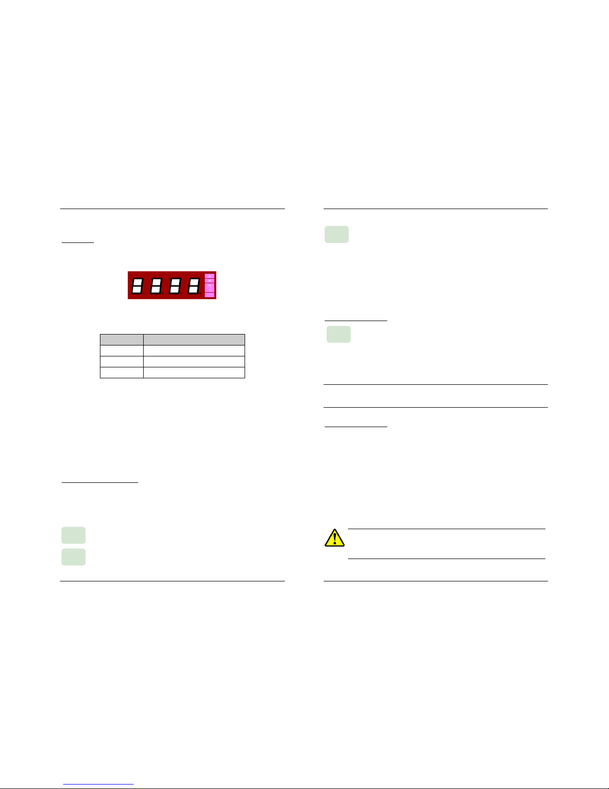
Display #2
All the PTE-100-C output magnitudes are shown on Display #2, located
above the variac’s knob:
The units in which the various possible readings are represented are labeled
on the right edge ot this LED display:
INDICATORS UNITS
A Current in Amps.
V Voltage in Volts.
% Percentage of the nominal current.
The following measurements can be read on this display:
Output current in Amperes.
AC or DC voltage present in Out 1 or Out 2 power taps and also
in Out 3 auxiliary DC voltage tap (regulated independently).
Percentage of the ‘nominal’ current value entered in Display #1 by
means of the “%” special function.
The floating decimal point is automatically placed to accommodate the
reading to the working regulation range.
Displaying the used output
Variable output magnitudes are shown in Display #2, used as an ammeter
by default. Since there are several output taps but only one display, you
need to select the tap to be displayed by pressing the corresponding display
assignment buttons:
Press this button to view the voltage present in Out 1 (variable
0-250 VAC).
Press this button to view the voltage present in Out 2 (variable
0-350 VDC).
Out 2
Out 1
USER’S MANUAL
14
Press this button to view the voltage present in Out 3 (auxiliary
variable 0-250 VDC). Out 3, located in the center section of
the PTE-100-C panel, is switched on, regulated and protected
independently from the other outputs.
A green LED above its tap will identify the displayed output. If you want to
lock the Display #2 to Out1, Out2 or Out3, press the corresponding display selection button and hold it for 5 seconds until you hear a beep. To
return to the normal ammeter function, give a brief press to any of these
buttons.
Current tap selection.
The PTE-100-C cannot detect which of the current taps is con-
nected the load to. Though the current value shown by Display
#2 is common to the four taps, some special functions, overload protections
and calculations require that the current output tab to which the load is
actually connected is identified to the unit. Press this key to sequentially signal the 100 A, 50 A, 25 A or 5 A tap in use.
Though this will not affect the output current nor the value shown in Display #2,
we strongly recommend you to do it whenever you move your connections to a
different current output.
Power Section Alarms
The PTE-100-C’s power section is protected form over-heating and from
overload. These conditions will automatically switch the power output off
and will be signaled by these two orange-colored 3-mm LEDs:
• I Therm. An internal sensor will protect the unit from overheating. This
alarm automatically disappears when the unit cools down to
normal temperature. Operation can then be resumed.
• I Lim. This protection operates when the upper limit of the selected
current tap, or the limit optionally set with the “Ilim” special
function, whichever is lowest, has been exceeded.
Up to 250 A can be attained from the 100A/10V tap for 3 seconds
before the unit’s thermal protection trips. Refer to the duty cycle chart
in the CURRENT AND VOLTAGE INJECTION chapter to learn more on
how to get currents higher than 100 A from this tap.
Out 3
Tap
 Loading...