

Page 1

Technical Specification
Pressure Sensor
PSE540 Series
No.: PS##-OMG0004
Page 2

Contents
Safety
Model Indication Method
Specification
Full View with Dimensions
Installation
Examples of Internal Circuit and Wiring
……………………………………………………… P2
……………………………………………………… P6
……………………………………………………… P7
……………………………………………………… P8
……………………………………………………… P9
……………………………………………………… P9
- 1 -
PS##-OMG0004
Page 3
Safety
♦
The Pres su re Sens o r and thi s tech ni c al spec if ication contain e s se nti al i nfo rmation for the protecti on of
users and others from possible injury and damage to property and to ensure correct handling.
Please chec k th at yo u f ul l y un de rs tand the defi ni ti on o f the following m es sages (signs ) before going on
to read the text, and always follow the instructions.
Also read carefully the technical specification of relevant equipment or apparatus before use.
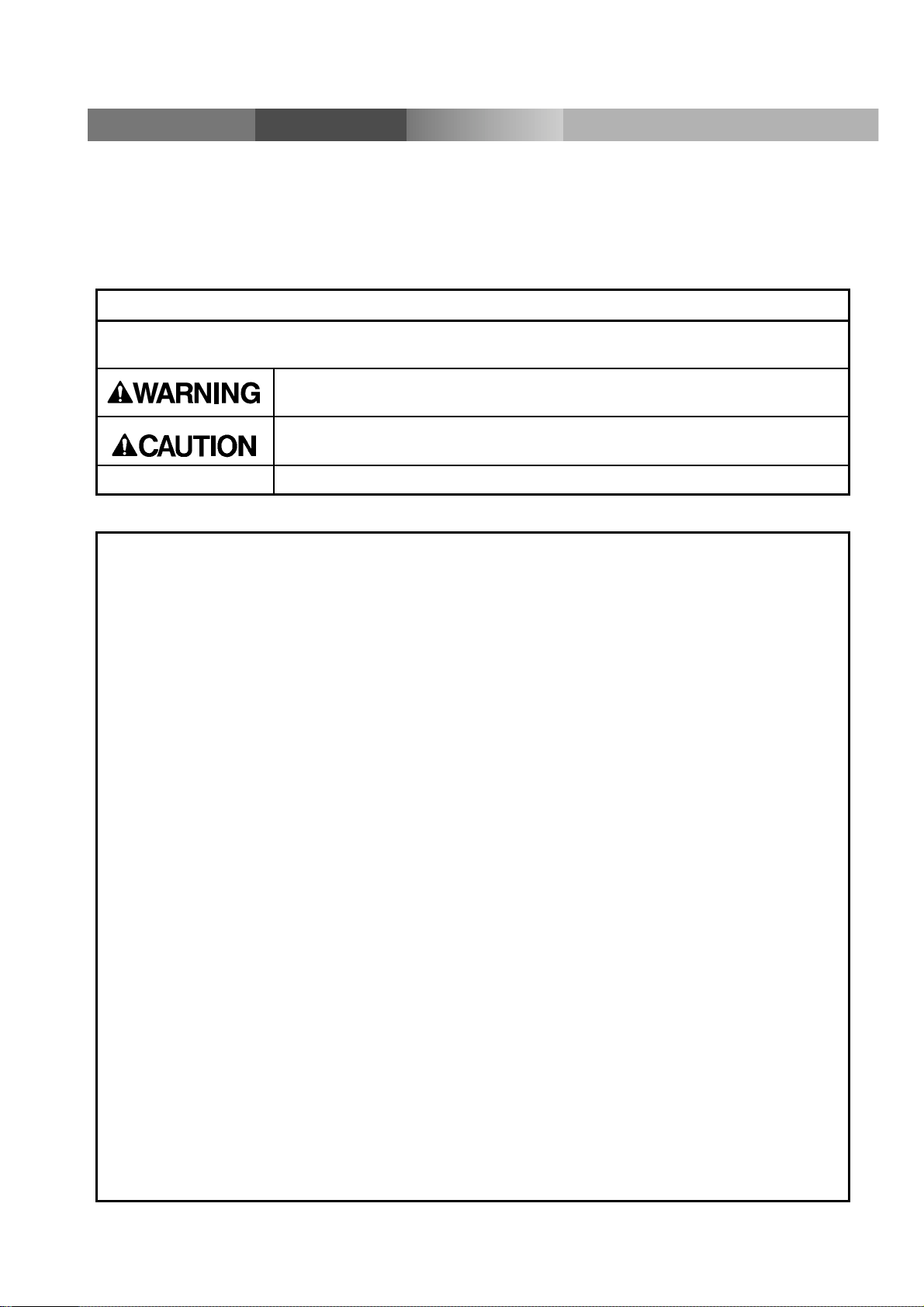
Indications
IMPORTANT MESS AGES
Read this manual and follow its instructions. Signal words such as WARNING,CAUTION and
NOTE, will be followed by important safety information that must be carefully reviewed.
Indicates a potentially hazardous situation which could result in death
or serious injury if you do not follow instructions.
Indicates a potentially hazardous situation which if not avoided, may
result in minor injury or moderate injury.
NOTE
Gives you helpful information.
♦ Usage Restrictions
n
This product is designed for use in general equipment for factory automation. Never use this
product with equipment or apparatus that directly concerns human lives*
1
, or which
malfunction or failure can cause a huge loss.
*1: Equipment or apparatus that directly matters human lives means the following:
⋅ Medical equipment such as life support systems or equipment used in operating rooms
⋅ Compulso ry e qui pment re qu ire d by law su ch a s the Fire P rev ent io n Law, Constru ctio n L aw a nd etc .
⋅ Equipmen t or app ar at us t hat c onf or ms w ith t ho se men t ion ed ab ov e.
n
Contact our sales department when plans are made for the product to be used for the system*
including equipment that concerns itself with the safety of persons or that seriously affects the
public. Th i s us age ne ed s spec i al c onsi de ra tio n*
3
.
*2: Th e sy st em in c lud ing equi pm ent t h at co nce rn s it sel f wi th t he saf ety of per son s o r that seri ous ly
affec ts the pu blic mea ns t he fo llow i ng:
⋅ Nuclear reactor control systems in nuclear power plants, safety protection systems or
other systems important for safety in nuclear power facilit ies
⋅ Driving control systems of mass transportation systems, and flight control systems
⋅
Equipment or apparatus that comes into contact with foods or beverages
*3: S p ecia l c ons ide rat io n mean s disc us si ng us ag e wit h our e ng ine ers t o establish a safe sys te m
designed as fool-proof, fail-safe, redundant and etc.
2
n
Special consideration of safety or maintainability should be taken to prevent hazard or loss
caused by a failure or malfunction that is likely to occur in certain probability due to
environmental stress (deterioration).
L
The special consideration means to fully review the equipment or apparatus in design stage
and to establish a backup syste m in adva nce such as a redundant system or fail-safe system.
n
Use for an interlocking ci r cuit
When using the pressure sensor as a sensor for interlock, adopt a double interlocking method
such a s equi ppin g the mec hanic al pr otect ion f unct ion i n or der t o deal with a pr essur e se nsor
failure.
Check the pressure sensor regularly to ensure proper operation.
- 2 -
PS##-OMG0004
Page 4

♦♦♦♦ Operator
This technical specification has been written for those who have knowledge of machinery and
♦♦♦♦
apparatus that use pneumatic equipment and have full knowledge of assembly, operation and
maintenance of such equipment.
♦♦♦♦Please rea d thi s te chn i c al s p ecification care full y and understa nd it be fo re as se m bl i n g, op er a ti n g o r
providing maintenance to the pressure sen sor.
♦♦♦♦ Safe ty
♦♦♦♦ Do not dis a ssembl e, modify (including chang e of printed circuit board) or repair.
An injury or failure can result.
♦
♦ Do not operate beyond specification range.
♦♦
Do not use the pressure sensor for inflammable or har m ful gas or fluid.
Operation at a range that exceeds the specifications can cause a fire, malfunction, or damage to
the pressure sensor.
Verify the specifications before use.
Do not use it in an atmosphere of an inflammable, an explosive and corrosive gas.
♦♦♦♦
A fire, explosion and c orrosion can result.
This press ure sensor i s not an explosion-proof ty pe.
These instructions must be followed when using this pressure sensor in an interlocking circuit:
♦♦♦♦
⋅ Provide double interlocking by another system such as mechanical protection.
⋅ Check t he c press ur e sensor r egularl y to ensure proper operation.
Other wise malfunctio n can cause an accident.
These instructions must be followed while in maintenance:
♦♦♦♦
Turn off the power supply.
⋅
Stop the supplied air, exhaust the residual pressure and verify the release of air before
⋅
performing mai ntenance.
Other wise it can cause in jury.
♦♦♦♦ Perform proper functional checks and leak tests after maintenance.
Stop operation when an abnormality is observed such that the sensor does not work properly or
there is a leakage of fluid.
Safety is not be assured due to unexpected malfunction.
- 3 -
PS##-OMG0004
Page 5

NOTE
t
Follow the instruction given below when designing, selection and handling your pressure sensor.
• The instructions on design and selection.
Installation, wiring, en vironm ent of use, adj ustment, operation and m aint enance d escribed belo w must also b e
followed.
• Product specifications
⋅ Operate the pressure sensor with the specified voltage.
Operation with a voltage beyond specifications can cause malfunction or damage of the pressure sensor. Insufficien
supply voltage may not drive a load due to a voltage drop inside the pressure sensor. Verify the operating voltage of the
load before use.
⋅ Do not operate beyond specification range.
Fire, malfunction or sensor damage can result.
⋅ Do not exceed the specified maximum allowable load.
Otherwise it can cause damage or shorten the lifetime of the pressure sensor.
⋅ Reserve a space for maintenance.
Remember to leave space for maintenance.
• Product handling
• Installation
⋅ Do no drop, hit or apply excessive shock (980 m/s
Otherwise it can result in damage to the pressure sensor causing failure or malfunction.
⋅ Do not pull lead wires or lift the body with lead wires. ( P ul lin g stren gth les s than 50N)
Hold the body when handing. Otherwise it can result in damage of the pressure sensor causing failure or malfunction.
⋅ Follow the specified tightening torque
Excessive tightening torque can break the pressure sensor. Insufficient tightening torque can displace the pressure
sensor from the original position or loosen the mounting screws. The standard torque of the fittings are as shown in
below.
M3 : Tighten by hand, then turn it 1/4 revolutions with a wrench
M5 : Tighten by hand, then turn it 1/6 revolutions with a wrench
R
⋅NPT1/8 : 7 to 9 N⋅m
⋅ When piping, apply the wrench only to the metal option (attachment to be piped) integrated into the piping.
Applying the wrench in other position can break the press ure sensor.
⋅ Blow off all the dust inside the pipes before piping the pressure sensor.
Otherwise it can cause damage or malfunction.
⋅ When using tape sealant, leave a couple of screw threads unwrapped with tape sealant.
Otherwise it can cause damage or malfunction.
⋅ Do not insert wires or other foreign matter into the pressure measurement port.
It can damage the pressure sens or causing failure or malfunction.
⋅ Connect frame-ground terminal (FG terminal) to the ground when using a switching power supply.
⋅ Insert a noise filter (power line noise filter, ferrite core, etc.) between the switching power supply and this
pressure sensor.
2
) to the pressure sensor.
• Wi rin g
⋅ Do not bend or apply tensile stress to lead wires repeatedly.
Wiring with repetitive bending stress or tensile stress can cause breakage of the lead wires. Replace the product when
damage to a lead wire is observed.
⋅ Connect wires and cables correctly.
Miswiring can break the pressure sensor depending on a miswired circuit.
Do not connect wires while the power is on.
Otherwise it can break the circuit inside the pressure sensor causing malfunction.
⋅ Do not lay wires or cables with power cable or high-voltage cable in the same wiring route.
Otherwise the wires to the pressure sensor can be contaminated with noise or induced surge voltage from power lines
or high voltage lines causing malfunction. Lay the wires to the pressure sensor to a wire duct or in a protective tube
other than those for power lines or high voltage lines.
⋅ Verify the insulation of wiring.
Poor insulation (interference w ith ot her circuit, poor insulation between terminals and etc.) can introduce excess voltage
or current to the pressure sensor causing damage.
- 4 -
PS##-OMG0004
Page 6

⋅ Keep wiring as short as possible to prevent contamination from noise and induced surge voltage.
,
Do not use a cable longer than 10m. Consult with SMC for the use with a cable longer than 10 m.
Connect the 0V DC wire (blue line) directly or as close as possible to the 0V DC terminal of the DC power supply.
⋅ The direct-current p ower supply to com bine should use UL authorization power supply whic h is the class 2
power supply based on UL 1310 or the power supply is using the transformer of a class 2 based on UL 1585.
• Environment
⋅ Do not use the product in an atmosphere containing corrosive gas, chemicals, sea water, water or vapor, or in
a place where there is a possibility of adhesion of those substances to the product.
It can cause failure or malfunction.
⋅ Avoid exposure of this product to direct sunlight.
Use sunshades if the product is exposed to direct sunlig ht. Otherwise it can cause failure or malfunction.
⋅ Do not use in a place where water, oil or chemicals splashes.
Otherwise it can cause failure or malfunction.
⋅ Do not use a pressure sensor nearby a place where electric surges are generated.
Internal circuit elements of the pressure sensor can deteriorate or break when equipment generating a large surge
(electromagnetic lifter, high frequency induction furnace, motor, etc.) is located near the pressure sensor. Provide surge
preventives, and avoid interference.
⋅ Do not apply the pressure sensor to the load that generates electric surge voltage.
Relays or solenoid values generate electric surge voltage. When applying the pressure sensor to drive these loads
directly, use the product equipped with surge absorber.
⋅ The product is not resistiv e to a lightning surge def ined in CE marking. Take measures to protect against a
lightning surge at the load side.
⋅ Prevent foreign matter such as remnant of wires from entering this product.
Take proper measures for the remnant not to enter the pressure sensor in order to prevent failure or malfunction.
⋅ Do not expose the pressure sensor to vibration (less than 98 m/s2), and impact (less than 980 m/s2).
Otherwise it can cause damage or malfunction.
⋅ Follow the specified ranges of the operating fluid and maintain ambient temperatures.
The operating fluid and ambient temperatures should be in the range of 0 to 50 °C. When operating at low temperature
of 5°C or below, breakage or malfunction can occur to the pressure sensor due to freezing of condensed water in the
pressurized air. Take preventive measures against freezing. Do not use the pressure sensor in a place where
temperature suddenly changes even if it stays within the specified range.
⋅ Do not expose the pressure sensor to heat radiation from a heat source located nearby.
It can cause malfunction.
• Adjustment and Operation
⋅ Do not short-circuit the load.
Excess current can damage the pressure sensor.
⋅ A warm-up time of 20 to 30 minutes is needed for detection of low pressure.
The indication drifts about ±1% soon after the power is on.
• Maintenance
⋅ Before performing maintenance, make sure to turn off the power supply.
Otherwise an unexpected operation of the system component can oc cur.
⋅ Perform maintenance and check regularly.
Otherwise an unexpected malfunction of the system can occur due to a malfunction of the pressure sensor.
⋅ Perform a proper functional check after maintenance.
Stop operatio n when an abn ormality is observed such that the device does not work properly. Otherwise an unexpected
malfunction of the system component can occur.
Do not use solvents such as benzene or thinner to clean the pressure sensor body.
It can damage the surface of the body and erase the indication on the body.
Use a soft cloth to remov e st ains. For heav y st ains, use a cloth soak ed with d ilut ed neutra l deterg ent and fully sque ezed
then wipe up the stains again with a dry cloth.
- 5 -
PS##-OMG0004
Page 7

Model Indication Method
PSE54
-
Pipe Specification
-
Option
No symbol None
C1 Connector for PSE200 1pc
C2 Connector for PSE300 1pc
M3 M3 × 0.5
M5 M5 × 0.8
01 R1/8 (with M5 female screw)
N01 NPT1/8 (with M5 female screw)
R04
R06
IM5 M5 female screw, through type
IM5H M5 female screw, through type
φ
4 reducer
φ
6 reducer
with settinghole
Sensor Range
1
3 For compound [-100 to 100kP a ]
Options
Option products Model Note
Connector for PSE200
Connector for PSE300
For vacuum [ 0 to -101kPa ]
ZS
-26-E-
ZS
-28-
4 1pc
C 1pc
- 6 -
PS##-OMG0004
Page 8

A
Specification
Model PSE541 PSE543
Rated Pressure Range 0 to -101kPa
Withstand Pressur e 500kPa
Fluid Air, Non-corrosive gases, Incombustible gases
Power Supply Voltage 12 to 24VDC, ripple ( p-p ) ±10% or less ( Protected against inverse connection )
Current Consumption 15mA or less
Analog Output Analog output 1 to 5VDC ( Rated Pressure Range ), Output impedance : Approx.1k
Accuracy
(Ambient temp. 25°C)
Linearity
Repeatability
Influence from Power Supply
Voltage
Enclosure IP40
Opera ti ng Temp. R an g e Oper at io n: 0 to 50°C, Storage: -20 to 70°C ( No condensation or free zing )
Operating Humidity Range Operation, Storage: 35 to 85% RH ( No condensation )
Withstand Vol t a ge 1000VAC or more , 50 / 60 H z, 1m i nu t e ( Bet w ee n le ad blo ck an d c a se )
Insulation Resistance 50MΩor more ( 500VDC by Megameter ) ( Between lead block and case )
Environment
Vibration proof
10 to 500Hz smaller one 1.5mm or 98m/s
±
2%F.S. or less
±
0.4%F.S. or less
±
0.2%F.S. or less
±
0.8%F.S. or less
2
double amplitude each in directions of
X, Y and Z for 2 hours
-
100 to 100kPa
Ω
Impact proof 980m/s2, 3 times each in directions of X, Y and Z respectively
Temp. Characteristic
±
2%F.S. or less ( 25°C)
Pipe Spec ification
Model M3 M5 01 N01 R04 R06 IM5 IM5H
Port size M3 × 0.5 M5 × 0.8
Case : PBT
Material
Lead wir e 3-core s el l ipse-shaped ca b le ( 0. 15m m2 )
Mass
Piping port : SUS303
pplied
lead
wire
N/A
lead
wire
42.4g 42.7g 49.3g 41.4g 41.6g 43.3g 44.1g
2.9g 3.4g 9.8g 1.9g 2.1g 3.8g 4.6g
Pressure-detection component, Sensor receiving area : Silicon, O-ring : NBR
R1/8,
M5 × 0.8
Case : PBT
Piping po rt : C36 04 BD
NPT1/8,
M5 × 0.8φ4reducerφ6reducer
PBT
M5 female screw.
Through type
Piping po rt : A6063S-T5
M5 female screw.
Through type
with se t ti n g ho l e
Case : PBT
- 7 -
PS##-OMG0004
Page 9

Full View with Dimensions
PSE54 (A)
10
B
A
18 3000
13
9.6
PSE54 (A)
10
14.4
M3
-
M5
M3: M3 0.5
M5: M5
01
-
N01
01: R1/8
N01: NPT1/8
0.8
A
B 3.53
Width across flat 7
PSE54(A)-
M3
M5PSE54(A)-
11.510.8
M5 0.8
PSE54 (A)
10
B
-
R04
R06
A
PSE54 (A)-IM5
8.7
9
PSE54
(A)-IM5H
4
M5 0.8
PSE54(A)-
R04
A
B
R06PSE54(A)-
64
2018
8.7
13
3
7
3.4
M5 0.8
- 8 -
8
PS##-OMG0004
Page 10

Installation
Attaching the connector to the lead wire
⋅ Sensor wire is stripped as shown in the right figure.
⋅ The core of the corresponding color shown in the following table is put into the pin of
the number stamped on the connector for sensor connec t ion t o the back .
Pin No.
For PSE200(ZS-26-E-4) For PSE300(ZS-28-C)
1 Brown ( DC+ ) Brown ( DC+ )
2 Black ( IN : 1 to 5VDC ) NC
3 Blue ( DC- ) Blue ( DC- )
4 NC Black ( IN : 1 to 5VDC )
⋅ It checks that the above-mentione d preparation work has been performed
correctly, and A part shown in figure drawn up is pushed by hand and makes tempor ary connection.
⋅ A part cent er is straight ly pushed in by tools, such as pliers.
⋅ Re-use cannot be performed once it connects the connector for sensor connection completely.
⋅ When you fail in the connection mistake of a core and a pin, or the plug of wire, please use the new
connector for sensor connection.
⋅ When connecting the connector to PSE300 series, please use the connector for Sensor Lead Wire
( ZS-28-C ) or e-con as below.
Maker Model No.
( c ) Sumitomo 3M 37104-3101-000FL
Tyco Electronics AMP K.K. 1-1473562-4
Color of cable core
⋅ Please contact with each connector maker about e-con c atalog ue.
Connector
Connec tor Connecting/Disconnecting
⋅
When connecting the connector, insert it straight onto the pin and loc k the connector into the square groove
in the housing until connector clicks.
⋅
When disconnecting th e connector, push do wn the lever by thumb to disengage the lever claw from the
square groove. Then pull out the connect or straight .
Examples of Internal Circuit and Wiring
Output Specification
Volt age output : 1 to 5V
Output impedance : Approx. 1k
Ω
- 9 -
PS##-OMG0004
 Loading...