

SMC Networks PSE300 Operation Manual
No.PS※※-OMG0002-F
PRODUCT NAME
Pressure Sensor Controller
MODEL / Series / Product Number
PSE300

-1-
No.PS※※-OMG0002-F
Table of Contents
Safety Instructions 2
Model Indication and How to Order 8
Summary of Product parts 9
Mounting and Installation 10
Installation 10
Wiring 12
Internal circuit and wiring example 14
Setting 16
Pressure Setting 19
Other Functions 21
Maintenance 23
Troubleshooting 24
Specification 31
Specifications 31
Dimensions 33
-2-
No.PS※※-OMG0002-F
Safety Instructions
These safety instructions are intended to prevent hazardous situations and/or equipment damage.
These instructions indicate the level of potential hazard with the labels of "Caution", "Warning" or
"Danger". They are all important notes for safety and must be followed in addition to International
standards (ISO/IEC)
1)
and other safety regulations.
1) ISO 4414: Pneumatic fluid power -- General rules relating to systems
ISO 4413: Hydraulic fluid power -- General rules relating to systems
IEC 60204-1: Safety of machinery -- Electrical equipment of machines (Part 1: General requirements)
ISO 10218-1: Manipulating industrial robots -Safety.
etc.
Caution :
CAUTION indicates a hazard with a low level of risk which, if not avoided,
could result in minor or moderate injury.
Warning :
WARNING indicates a hazard with a medium level of risk which, if not
avoided, could result in death or serious injury.
Danger :
DANGER indicates a hazard with a high level of risk which, if not avoided,
will result in death or serious injury.
Warning
1. The compatibility of the product is the responsibility of the person who designs the
equipment or decides its specifications.
Since the product specified here is used under various operating conditions, its compatibility with specific
equipment must be decided by the person who designs the equipment or decides its specifications based on
necessary analysis and test results. The expected performance and safety assurance of the equipment will be
the responsibility of the person who has determined its compatibility with the product. This person should also
continuously review all specifications of the product referring to its latest catalog information, with a view to giving
due consideration to any possibility of equipment failure when configuring the equipment.
2. Only personnel with appropriate training should operate machinery and equipment.
The product specified here may become unsafe if handled incorrectly. The assembly, operation and
maintenance of machines or equipment including our products must be performed by an operator who is
appropriately trained and experienced.
3. Do not service or attempt to remove product and machinery/equipment until safety is confirmed.
1. The inspection and maintenance of machinery/equipment should only be performed after measures to prevent
falling or runaway of the driven objects have been confirmed.
2. When the product is to be removed, confirm that the safety measures as mentioned above are implemented
and the power from any appropriate source is cut, and read and understand the specific product precautions of
all relevant products carefully.
3. Before machinery/equipment is restarted, take measures to prevent unexpected operation and malfunction.
4. Contact SMC beforehand and take special consideration of safety measures if the product is
to be used in any of the following conditions.
1. Conditions and environments outside of the given specifications, or use outdoors or in a place exposed to direct
sunlight.
2. Installation on equipment in conjunction with atomic energy, railways, air navigation, space, shipping, vehicles,
military, medical treatment, combustion and recreation, or equipment in contact with food and beverages,
emergency stop circuits, clutch and brake circuits in press applications, safety equipment or other applications
unsuitable for the standard specifications described in the product catalog.
3. An application which could have negative effects on people, property, or animals requiring special safety
analysis.
4. Use in an interlock circuit, which requires the provision of double interlock for possible failure by using a
mechanical protective function, and periodical checks to confirm proper operation.
-3-
No.PS※※-OMG0002-F
Caution
The product is provided for use in manufacturing industries.
The product herein described is basically provided for peaceful use in manufacturing industries.
If considering using the product in other industries, consult SMC beforehand and exchange specifications or
a contract if necessary.
If anything is unclear, contact your nearest sales branch.
Limited warranty and Disclaimer/Compliance Requirements
The product used is subject to the following "Limited warranty and Disclaimer" and "Compliance
Requirements".
Read and accept them before using the product.
Limited warranty and Disclaimer
1. The warranty period of the product is 1 year in service or 1.5 years after the product is delivered,
whichever is first.
2)
Also, the product may have specified durability, running distance or replacement parts. Please
consult your nearest sales branch.
2. For any failure or damage reported within the warranty period which is clearly our responsibility, a
replacement product or necessary parts will be provided.
This limited warranty applies only to our product independently, and not to any other damage
incurred due to the failure of the product.
3. Prior to using SMC products, please read and understand the warranty terms and disclaimers noted
in the specified catalog for the particular products.
2) Vacuum pads are excluded from this 1 year warranty.
A vacuum pad is a consumable part, so it is warranted for a year after it is delivered.
Also, even within the warranty period, the wear of a product due to the use of the vacuum pad or failure due to
the deterioration of rubber material are not covered by the limited warranty.
Compliance Requirements
1. The use of SMC products with production equipment for the manufacture of weapons of mass
destruction (WMD) or any other weapon is strictly prohibited.
2. The exports of SMC products or technology from one country to another are governed by the
relevant security laws and regulation of the countries involved in the transaction. Prior to the
shipment of a SMC product to another country, assure that all local rules governing that export are
known and followed.
Caution
SMC products are not intended for use as instruments for legal metrology.
Products that SMC manufactures or sells are not measurement instruments that are qualified by pattern
approval tests relating to the measurement laws of each country.
Therefore, SMC products cannot be used for business or certification ordained by the measurement laws of
each country.
-4-
No.PS※※-OMG0002-F
Operator
This operation manual is intended for those who have knowledge of machinery using pneumatic
equipment, and have sufficient knowledge of assembly, operation and maintenance of such
equipment. Only those persons are allowed to perform assembly, operation and maintenance.
Read and understand this operation manual carefully before assembling, operating or providing
maintenance to the product.
■Safety Instructions
Warning
■Do not disassemble, modify (including changing the printed circuit board) or repair.
An injury or failure can result.
■Do not operate the product outside of the specifications.
Do not use for flammable or harmful fluids.
Fire, malfunction, or damage to the product can result.
Verify the specifications before use.
■Do not operate in an atmosphere containing flammable or explosive gases.
Fire or an explosion can result.
This product is not designed to be explosion proof.
■Do not use the product in a place where static electricity is a problem.
Otherwise it can cause failure or malfunction of the system.
■If using the product in an interlocking circuit:
Provide a double interlocking system, for example a mechanical system
Check the product regularly for proper operation
Otherwise malfunction can result, causing an accident.
■The following instructions must be followed during maintenance:
Turn off the power supply
Stop the air supply, exhaust the residual pressure and verify that the air is released before performing
maintenance
Otherwise an injury can result.
-5-
No.PS※※-OMG0002-F
Caution
■Do not touch the terminals and connectors while the power is on.
Otherwise electric shock, malfunction or damage to the product can result.
■After maintenance is complete, perform appropriate functional inspections and leak tests.
Stop operation if the equipment does not function properly or there is a leakage of fluid.
When leakage occurred from other parts except piping, the product might break.
Cut off power supply and stop supplying fluid.
Do not apply fluid at leaking condition.
Safety cannot be assured in the case of unexpected malfunction.
■NOTE
○Follow the instructions given below when designing, selecting and handling the product.
●The instructions on design and selection (installation, wiring, environment, adjustment,
operation, maintenance, etc.) described below must also be followed.
Product specifications
Operate the product with the specified voltage.
Operation with a voltage beyond specifications can cause malfunction or damage of the product.
Insufficient supply voltage may not drive a load due to a voltage drop inside the product.
Verify the operating voltage of the load before use.
Use the pressure sensor within the specified ranges of the measurement flow rate and under the
specified operating pressure.
Otherwise it can cause damage to the product and an abnormal measurement.
Do not exceed the specified maximum allowable load.
Otherwise it can cause damage or shorten the lifetime of the product.
Reserve a space for maintenance.
Remember to leave space for maintenance when designing the piping plan.
The direct-current power supply to combine should use UL authorization power supply which is the
Class 2 power supply based on UL1310 or the power supply is using the transformer of a Class 2 based
on UL1585.
The product is a UL approved product only if it has a
mark on the body.
●Product handling
Installation
Do no drop, hit or apply shock to the product.
Otherwise it can result in damage to the product causing failure or malfunction.
Do not pull cables or lift the body with cables.
Hold the body when handing.
Otherwise it can result in damage of the product causing failure or malfunction.
Follow the specified tightening torque.
Excessive tightening torque can break the product, bracket, and mounting screws. Insufficient tightening torque
can displace the product from the original position or loosen the mounting screws.
Do not apply excessive external force with joints such as hoses when installing with a panel mount
adapter.
Otherwise it can damage the pipe joint of the product or cause drop off from the panel mount adapter.
Connect frame-ground terminal (FG terminal) to the ground when using a switching power supply.
Insert a noise filter (power line noise filter, ferrite core, etc.) between the switching power supply and
product when using analogue output.

-6-
No.PS※※-OMG0002-F
Wiring
Do not bend or apply tensile stress to cables repeatedly.
Wiring with repetitive bending stress or tensile stress can cause breakage of the cables.
Replace the product when damage to a cable is observed.
The recommended bend radius of the cable is 6 times the outside diameter of the sheath, or 33 times the outside
diameter of the insulation material, whichever is larger.
Connect wires and cables correctly.
Miswiring can break the product depending on a miswired circuit.
Do not attempt to insert or pull out the pressure sensor or its connector when the power is on. Switch
output may malfunction.
Do not connect wires while the power is on.
Otherwise it can break the circuit inside the product causing malfunction.
Do not lay wires or cables with power cable or high-voltage cable in the same wiring route.
Otherwise the wires to the product can be contaminated with noise or induced surge voltage from power lines or
high voltage lines causing malfunction. Lay the wires to the product to a wire duct or in a protective tube other than
those for power lines or high voltage lines.
Verify the insulation of wiring.
Poor insulation (interference with other circuit, poor insulation between terminals and etc.) can introduce excess
voltage or current to the product causing damage.
Keep wiring as short as possible to prevent contamination from noise and induced surge voltage.
Do not use a cable longer than 10 m. Consult with SMC for the use with a cable longer than 10 m.
Connect the 0 VDC wire (blue line) directly or as close as possible to the 0 VDC terminal of the DC power supply.
Environment
Do not use the product in an atmosphere containing corrosive gas, chemicals, seawater, water or vapor,
or in a place where there is a possibility of adhesion of those substances to the product.
It can cause failure or malfunction.
Avoid exposure of this product to direct sunlight.
Use sunshades if the product is exposed to direct sunlight.
Otherwise it can cause failure or malfunction.
Do not use in a place where water, oil or chemicals splashes.
Otherwise it can cause failure or malfunction.
Do not use a product nearby a place where electric surges are generated.
Internal circuit elements of the product can deteriorate or break when equipment generating a large surge
(electromagnetic lifter, high frequency induction furnace, motor, etc.) is located near the product. Provide surge
preventives, and avoid interference.
Do not apply the product to the load that generates electric surge voltage.
Relays or solenoid values generate electric surge voltage. When applying the product to drive these loads directly,
use the product equipped with surge absorber.
The product is not resistive to a lightning surge defined in CE marking. Take measures to protect
against a lightning surge at the load side.
Prevent foreign matter such as remnant of wires from entering this product.
Take proper measures for the remnant not to enter the product in order to prevent failure or malfunction.
Mount the product in a place that is not exposed to vibration or impact.
Otherwise it can cause damage or malfunction.
Follow the specified ranges of the operating fluid and maintain ambient temperatures.
The operating fluid and ambient temperatures should be in the range of 0 to 50 °C.
When operating at low temperature of 5 °C or below, breakage or malfunction can occur to the product due to
freezing of condensed water in the pressurized air.
Take preventive measures against freezing. Do not use the product in a place where temperature suddenly
changes even if it stays within the specified range.
Do not expose the product to heat radiation from a heat source located nearby.
It can cause malfunction.

-7-
No.PS※※-OMG0002-F
Adjustment and Operation
Do not short-circuit the load.
Do not press the buttons with a sharp object.
It can cause damage to the setting buttons.
A warm-up time of 20 to 30 minutes is needed for detection of low pressure.
The indication drifts about 1% soon after the power is on.
Do not touch the LCD during operation.
The indication on the LCD changes due to static electricity.
Maintenance
Before performing maintenance, make sure to turn off the power supply.
Otherwise an unexpected operation of the system component can occur.
Perform maintenance and check regularly.
Otherwise an unexpected malfunction of the system can occur due to a malfunction of the product.
Perform a proper functional check after maintenance.
Stop operation when an abnormality is observed such that the device does not work properly.
Otherwise an unexpected malfunction of the system component can occur.
Do not use solvents such as benzene or thinner to clean the product body.
It can damage the surface of the body and erase the indication on the body.
Use a soft cloth to remove stains. For heavy stains, use a cloth soaked with diluted neutral detergent and fully
squeezed, then wipe up the stains again with a dry cloth.
-8-
No.PS※※-OMG0002-F
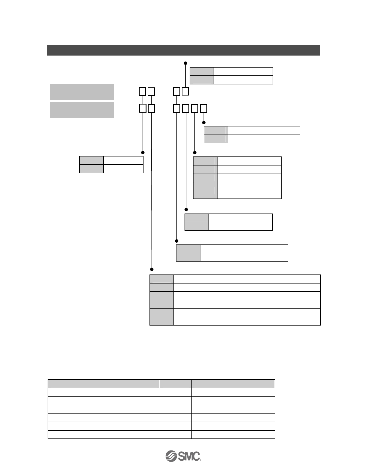
Model Indication and How to Order
PSE3 T
PSE3
: A unit label is attached.
1: The new Measurement Law prohibits use in Japan of products with a unit selection function.
2: Fixed unit for compound, vacuum, low and differential pressure is: kPa
for positive pressure is: MPa (kPa for 500 kPa range model)
○Options
Option products Model Note
Power and output cable ZS-28-A Length 2 m
Bracket ZS-28-B With set screws M3 x 5 L (2 pcs.)
Connector for sensor cable ZS-28-C 1 pc.
Panel mount adapter ZS-27-C With set screws M3 x 8 L (2 pcs.)
Panel mount adapter + Front protective cover ZS-27-D With set screws M3 x 8 L (2 pcs.)
Front protective cover ZS-27-01 1 pc.
DIN rail and terminal
base type
Option 1
Nil No option
L Power and output cable
Input/output specification
0 NPN open collector 2 outputs + 1 to 5 VDC Analogue output
1 NPN open collector 2 outputs + 4 to 20 mA Analogue output
2 NPN open collector 2 outputs + Auto-shift input
3 PNP open collector 2 outputs + 1 to 5 VDC Analogue output
4 PNP open collector 2 outputs + 4 to 20 mA Analogue output
5 PNP open collector 2 outputs + Auto-shift input
Unit specification
Nil Unit selection function provided
1
M SI units fixed
2
Option 2
Nil No option
A Bracket
B Panel mount adapter
D
Panel mount adapter
+ Front protective cover
Connector mounting
type
Option
Nil No option
E Front protective cover
Input specification
0 Voltage input
1 Current input
Option 3
Nil No option
C Connector for sensor cable
-9-
No.PS※※-OMG0002-F
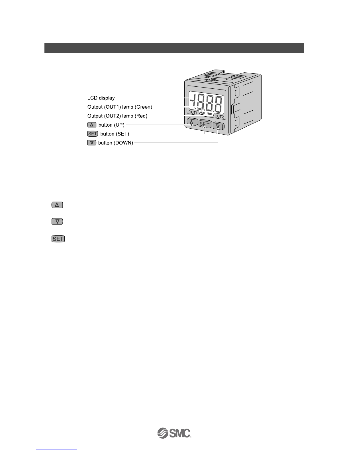
Summary of Product parts
○Names of individual parts
Output (OUT1) lamp (Green): Lit when OUT1 is ON.
Output (OUT2) lamp (Red): Lit when OUT2 is ON.
LCD display: Displays the current status of pressure, setting mode, selected indication unit and error code.
Four display modes can be selected: display always in red or green only, or changing from
green to red linked to output.
button (UP): Selects a mode and increases a set ON/OFF value.
Press this button to change to the peak display mode.
button (DOWN): Selects a mode and decreases a set ON/OFF value.
Press this button to change to the bottom display mode.
button (SET): Changes the mode and sets a set value.
-10-
No.PS※※-OMG0002-F
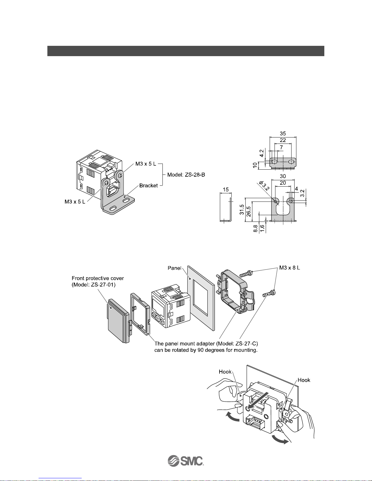
Mounting and Installation
■Installation
<PSE3 >
○Mounting
●Mount the optional bracket and panel mount adapter to the product.
○Mounting by bracket
●Fix the bracket to the product with the set screws M3 x 5 L (2 pcs.) as attached.
●The tightening torque of the set screws must be 0.5 to 0.7 Nm.
○Mounting by panel mount adapter
●Fix the panel mount adapter to the product with the set screws M3 x 8 L (2 pcs.) as attached.
○Notice when removing the controller
●The controller with adapter for panel mounting can be
removed from facility by making hook of the controller
wide as illustration after removing two screws.
Pressure sensor controller and panel mount adapter
may be damaged.

-11-
No.PS※※-OMG0002-F
<PSE3 T>
●Mounting
Hang the Hook 1 at the bottom of the body on the DIN rail as shown in Fig. a, press it in arrowed direction
to fix.
●Removing
For removal, pull it with a flat driver in arrowed direction shown in Fig. b.
 Loading...